1
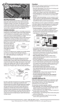
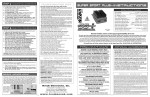
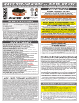
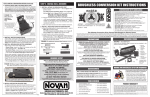
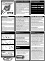
OPERATING INSTRUCTIONS
Part #1660
DUALLY DUAL-PROFILE
The Novak Dually is a microprocessor-based high-frequency
ESC (Electronic Speed Control) using advanced components
and the best HYPERFET III transistors for high performance.
The Dually Dual-Profile ESC gives you extra flexibility with
two user-selectable throttle profiles for optimum control
of both modified and stock motors with a single speed
control. The Dually also has Novak’s CLC III current limiter
that delivers extra smooth control, and is adjustable from
20 to 120 amps or completely off for full power.
With Novak’s exclusive Polar Drive Technology™, and Digital
Anti-Glitch Circuitry™, the Dually runs faster, longer, and
smoother than other speed controls.
Set-up is quick and easy with Novak’s original One-Touch
Set-Up™, and Radio Priority Circuity™ maintains complete
control of the vehicle’s steering servo even after the battery
pack has dumped and can no longer run the motor. The
Dually’s heavy-duty BEC (Battery Eliminator Circuit) handles
today’s high power servos.
Other features include the Novak Input Plug System™ for
compatibility with all major radio systems, Thermal Overload Protection, and purple anodized Micro Fin™ heat sinks
for optimum cooling and performance.
SPECIFICATIONS
Input Voltage
Case Width
Case Depth
Case Height
Weight (w/o heat sinks)
On-Resistance @ Transistors
Rated Current
Braking Current
BEC Voltage / Current
Wire Size (Battery/Motor)
Wire Length (Battery/Motor)
Signal Harness Length
Transistor Type
Current Limiter Range
Throttle Profiles
PWM Drive Frequency
Minimum Drive (% Full Drive)
4-7 cells (1.2 volts DC/cell)
1.63 inches [4.14 cm]
1.72 inches [4.37 cm]
0.65 inch
[1.65 cm]
2.10 ounces [59.53 g]
0.0007 Ω
@ 25°C transistor
400 amps
junction temp.
100 amps
6.0 volts DC / 3.0 amps
14 gauge
9 inches
[22.8 cm]
8 inches
[20.3 cm]
HYPERFET III
20 to 100 amps / OFF
(1) Modified (2) Stock
(1) 7.8 kHz (2) 1.0 kHz
(1) 3 %
(2) 6 %
ACCESSORIES
PRECAUTIONS
RADIO INTERFERENCE
MOTOR CAPACITORS
The high frequency switching operation of electronic
speed controls can generate radio interference. Here are
some common causes of radio interference problems:
The added cooling that is provided by heat sinks will
result in increased efficiency and optimum speed control
operation. A replacement Heat Sink Set for the Dually is
available as Novak kit #5403. Heat sinks are required with
the Dually, and all applications should allow adequate air
circulation through the heat sink’s fins to provide proper
speed control cooling.
• READ INSTRUCTIONS CAREFULLY BEFORE USING!
• WATER & ELECTRONICS DON’T MIX! Do not operate
model in or around water. Never allow water, moisture,
or other foreign materials to get inside the ESC.
• 4 to 7 CELLS ONLY Never use more than 7 cells (8.4
volts DC) in the main battery pack.
• MOTOR CAPACITORS REQUIRED Three 0.1µF (50V)
ceramic capacitors must be properly installed on every
motor to prevent radio interference.
• NO REVERSE VOLTAGE! Reverse battery polarity can
damage speed control––Disconnect battery immediately.
• DON’T LET TRANSISTOR TABS TOUCH Never allow
the two transistor tab banks to touch each other or any
exposed metal, as this will create a short circuit and
damage the speed control.
• DISCONNECT THE BATTERIES Always disconnect the
battery pack from the speed control when not in use.
• TRANSMITTER ON FIRST Always turn on the power of
your transmitter first so that you will have control of the
radio equipment when you turn on the speed control.
• DON’T GET BURNT! Transistor tabs can get hot, so be
careful not to touch them until they cool. If transistor
tabs get extremely hot use optional heat sinks.
• INSULATE WIRES Always insulate exposed wiring with
heat shrink tubing to prevent short circuits.
STEP 1
STEP 2
STEP 3
Included with the Dually ESC is the Novak Input Plug
SystemTM to convert the Futaba J style signal harness to
be compatible with Sanwa, KO, Kyosho, JR, and Hitec
radios. Refer to Figures 1 through 3 to convert plug.
1. DETERMINE THE BEST ESC MOUNTING LOCATION
Refer to Set-Up photo on back
To prevent radio interference problems, you must have
three 0.1µF capacitors properly installed on every motor.
Included with the Dually speed controls are three 0.1µF
(50v) capacitors for one motor. Additional 0.1µF (50V)
capacitors are also available in Novak kit #5620.
Refer to Step 3 for motor capacitor installation instructions.
SCHOTTKY DIODES
The Dually has an internal Schottky diode, and does not
require an external Schottky diode. However, an optional
external Schottky diode can also be added for increased
performance. Refer to Step 3 for installation instructions.
Additional Schottky diodes are available in Novak kit #5640.
HEAT SINKS
CHANGING THE INPUT PLUG
MOUNTING INSTRUCTIONS
KO
Kyosho (KYO)
JR/Hitec/AirZ
FIGURE 1 With a small standard screwdriver, press on
each of the three metal prongs until the wires are easy to
remove. Remove wires.
The speed control should be positioned away from the
receiver and antenna as shown in set-up photo on back
page. Choose a mounting position that will keep power
wires away from the receiver and antenna. Choose a
position that will provide maximum airflow through the
transistor tabs or heat sinks to allow for proper cooling.
Use the included double-sided tape to mount ESC.
3. INSTALL THE ON/OFF SWITCH
Determine a convenient place to mount the switch
where it will be easy to get to. Mount switch using a
piece of double-sided tape or with a screw through the
hole in the base of the switch housing.
4. INSTALL THE RECEIVER AND ANTENNA
FIGURE 2 With the screwdriver, carefully lift each of the
metal locking tabs to the angle shown.
Mount receiver as far from ESC, motor, power wires,
battery, and servo as possible. These components all
emit radio noise when the throttle is being applied. On
graphite or aluminum, it may help to place the receiver
on edge with the crystal and antenna as far above the
chassis as possible. Mount the antenna close to the receiver
and trail any excess wire off the top of the antenna mast.
Cutting or coiling excess wire will reduce radio range.
HOOK-UP INSTRUCTIONS
1. INSTALL MOTOR CAPACITORS
(Sanwa plug shown)
The locking tab must not extend
outside the plastic plug housing.
WHT = White wire terminal (signal)
BLK = Black wire terminal (negative)
RED = Red wire terminal (positive)
CAUTION Improper installation of these wires may cause
damage to the receiver, servo, and speed control.
• MOTOR BRUSHES WORN
As motor brushes continue to wear, excessive motor
noise will be generated. To avoid radio interference,
worn motor brushes should be replaced. The motor
commutator may also need to be cleaned or trued and
can be machined to help the motor run more efficiently.
2. CONNECT SPEED CONTROL TO THE RECEIVER
After the proper input plug plastic has been installed
to match the receiver (Refer to Step 1), plug the speed
control into the THROTTLE CHANNEL of the receiver.
3. CONNECT SPEED CONTROL TO THE BATTERY PACK
Cut the BLACK wire of speed control to the desired
length and strip about 1/8”-1/4” of insulation off the
end. Solder to the negative side of a completely
charged 4 to 7 cell battery pack (1.2 volts DC/cell).
Strip a short section of the insulation (1/4”-3/8”) from
the middle section of the speed control’s RED wire
where it will attach to positive of the battery pack.
Solder the stripped middle section of the RED wire to
positive of the battery pack.
4. CONNECT SPEED CONTROL TO THE MOTOR
Cut the RED wire (after battery pack connection) to the
desired length and strip about 1/8”-1/4” of insulation off
the end. Solder to the positive motor tab.
Cut the BLUE wire of speed control to desired length
and strip about 1/8”-1/4” of insulation off the end.
Solder to the negative tab of the motor.
TIP: Twisting the BLUE & RED motor wires one or two times
around each other as they go to motor can help reduce any
radio noise that may be emitted from the power wires.
5. USE OF OPTIONAL EXTERNAL SCHOTTKY DIODE
Solder the lead CLOSEST to the silver stripe on the body
of the Schottky diode to the POSITIVE (+) motor tab.
Solder the lead OPPOSITE the silver stripe on the body
of the Schottky to the NEGATIVE (–) motor tab.
STEP 3
FIGURE 3 Insert each pin into the correct plug slot. Each
pin should "click" into place.
• RECEIVER/ANTENNA INCORRECTLY MOUNTED
The receiver and antenna should be mounted as far
from the motor, power wires, battery, and servo as
possible, as these components all emit radio noise. On
graphite or aluminum, place the receiver on edge with
the crystal and the antenna as far above the chassis as
possible. Mount the antenna close to receiver and trail
any excess wire off the top of antenna.
Do not cut or coil excess wire!
HOOK-UP INSTRUCTIONS (Cont.)
2. INSTALL THE SPEED CONTROL
Sanwa (A)
• CAPACITORS NOT INSTALLED ON MOTOR
Electric motors generate radio noise that can interfere
with the operation of the receiver. To prevent radio
problems, every motor must have three 0.1µF (50V)
ceramic capacitors installed on it.
Refer to Step 3 for proper motor capacitor installation.
Electric motors generate radio noise that can interfere with
your receiver and cause radio problems. Included in the
accessory kit with the ESC are three 0.1µF (50V) nonpolarized, ceramic capacitors. These capacitors must be
installed on every motor to help reduce noise generated
by the motor and also to prevent possible ESC damage.
Solder 0.1µF (50V) capacitors between:
• POSITIVE (+) motor tab & NEGATIVE (–) motor tab.
• POSITIVE (+) motor tab & GROUND tab*.
• NEGATIVE (–) motor tab & GROUND tab*.
*If motor has no ground tab, solder the capacitors to motor can.
Negative (–) motor tab
0.1µF Capacitors
Schottky diode
Positive (+) motor tab
Ground / motor can
Extra 0.1µF capacitors are available in Novak kit #5620.
If installed backwards, a Schottky diode will be destroyed. The
body of a bad diode will normally crack open. Replace only with
Schottky diodes that have a minimum rating of 35 volts / 8 amps.
Schottky diodes are available in Novak kit #5640.
6. USING PLUGS FOR BATTERY & MOTOR CONNECTION
High-quality/low-resistance connector plugs, such as
Dean’s Ultra Plugs, can also be used to connect the
motor and battery pack. While connectors make component changes quick and easy, they will never have
the low resistance of a good solder joint.
Use connectors that can not be connected backwards.
It is always good practice to use the female connectors
on the battery packs to avoid short circuiting of the
connector and the battery pack.
If you use connectors for both the battery and the
motor, use a male connector on the speed control
wires going to the battery and a female connector on
the wires going to the motor. By doing this, you will
avoid plugging the battery pack into the speed
control’s motor output by mistake.
STEP 6
SET-UP PHOTO
Trail excess wire
off antenna mast.
(Do not cut or coil)
Blue wire
(motor negative)
TROUBLE-SHOOTING GUIDE
THROTTLE PROFILE SELECTION
The microprocessor in the Dually speed control allows you
to choose between two user-selectable throttle profiles that
are programmed at the factory. This chart gives you the
specifics of each profile:
(–)
Profile
Description
(**default)
1
2
(+)
**Modified
Stock
Drive Frequency
kHz
7.8
1.0
Minimum Drive
% Full Drive
3.0
6.0
Experiment with both profiles to determine which works best for you!
Red wire
(battery &
motor positive)
Tip: Twist motor
wires to reduce
radio noise!
TO SELECT THE THROTTLE PROFILE:
1. TURN ON THE TRANSMITTER
2. TURN ON THE SPEED CONTROL
3. PRESS & HOLD ESC’S ONE-TOUCH BUTTON until the
status LED turns solid green. The LED will first turn red,
then a few seconds later it will turn green.
(+)
4. RELEASE ONE-TOUCH BUTTON and then the status
LED will begin to blink red. The speed that the LED blinks
indicates the active profile.
Quick = MODIFIED
Slow = STOCK
5. PRESS & RELEASE ONE-TOUCH BUTTON TO SELECT
PROFILE Each press will change to next consecutive
profile number.
NOTE: After profile #2, the sequence begins again at profile #1.
6. If ONE-TOUCH button is not pushed for about five seconds,
the ESC LOADS THE SELECTED PROFILE INTO
MEMORY, and the status LED turns solid red, indicating
that the speed control has exited the profile selection
mode and is in neutral.
(–)
Black wire
(battery negative)
Illustration below shows graphical display of ESC parameters
Mount switch
where it will be
easy to get to.
Keep receiver and
antenna away from
motor, servo, battery,
and power wires.
STEP 4
SERVICE PROCEDURES
TRANSMITTER ADJUSTMENTS
For proper ESC operation adjust transmitter as follows:
1. Set HIGH ATV or EPA to maximum setting.
[Controls amount of throw from neutral to full throttle]
2. Set LOW ATV, EPA, or ATL to maximum setting.
[Controls amount of throw from neutral to full brakes]
[Reduce this after programming to reduce amount of brakes]
3. Set EXPONENTIAL to zero.
[Controls the linearity of the throttle channel]
4. Set THROTTLE CHANNEL TRIM to middle setting.
[Adjusts neutral position/Increases or decreases coast brakes]
5. Set CHANNEL REVERSING SWITCH to either position.
6. Set ELECTRONIC TRIGGER THROW ADJUSTMENT
to 70% throttle and 30% brake throw (or 7:3).
[Adjusts pistol-grip transmitter’s throttle trigger throw]
7. Set MECHANICAL TRIGGER THROW ADJUSTMENT
to position with 2/3 throttle and 1/3 brake throw.
[Adjusts pistol-grip transmitter’s throttle trigger throw]
STEP 5
SPEED CONTROL PROGRAMMING
Before beginning this step, the speed control should be
connected to the receiver and to a charged 4 to 7 cell
battery pack, and the transmitter should be adjusted.
1. CONNECT THE BATTERY
2. TURN ON TRANSMITTER THEN THE SPEED CONTROL
Slide the ON/OFF switch to the ON position.
3. PRESS AND HOLD ESC’S 1-TOUCH BUTTON
With the transmitter throttle in the neutral position,
press and hold the SET button on the speed control
until the status LED turns solid red.
4. RELEASE ESC’S 1-TOUCH BUTTON
5. PULL THROTTLE TO FULL-FORWARD POSITION
Hold it there until the status LED turns solid green.
NOTE: The motor will not run during programming even
if it is connected to the speed control.
6. PUSH THROTTLE TO FULL-BRAKE POSITION
Hold it there until the status LED blinks green.
7. RETURN TRANSMITTER THROTTLE TO NEUTRAL
The status LED will turn solid red, indicating that the
throttle is in the neutral position and also that proper
programming has been completed.
The speed control is programmed and ready to race!
If transmitter settings are changed, it will be necessary
to complete the programming sequence once again.
If you experience any problems during programming,
turn off the speed control and repeat programming.
NOVAK ELECTRONICS, INC.
18910 Teller Avenue
Irvine, CA 92612
949-833-8873
www.teamnovak.com
This section describes possible speed control problems,
causes, and solutions.
Steering Channel Works But Motor Will Not Run
• Speed control has thermally shut down––Allow ESC to
cool down––Use milder motor or smaller pinion gear.
• Check motor connections. Check motor and brushes.
• Make sure ESC is plugged into the throttle channel of
receiver. Check throttle channel operation with a servo.
Check wiring color sequence of receiver signal harness.
• Possible internal damage––Refer to Service Procedures.
Receiver Glitches/Throttle Stutters During Acceleration
• Motor capacitors broken or missing––Refer to Step 3.
• Receiver or antenna too close to speed control, power
wires, battery, or motor––Refer to Step 2.
• Bad connections––Check wiring and connectors.
• Motor brushes worn––Replace brushes.
• Excessive current to motor––Use a milder motor or a
smaller pinion gear.
Motor and Steering Servo Do Not Work
• Check wires, receiver signal harness wiring and color
sequence, radio system, crystals, battery and motor connectors, and battery pack.
• Possible internal damage––Refer to Service Procedures.
Model Runs Slowly / Slow Acceleration
• Check motor and battery connectors––Replace if needed.
• Bad battery or motor––Check operation with another.
• Incorrect transmitter or speed control adjustment––
Refer to Steps 4 and 5.
• Optional external Schottky diode installed backwards
or damaged––Refer to Step 3.
Motor Runs Backwards
• Motor wired backwards––Check wiring and reverse.
• Backwards motor timing––Reverse motor end bell.
ESC Is Melted Or Burnt/ESC Runs With Switch Off
• Internal damage––Refer to Service Procedures.
*For more help call our Customer Service Department.
STEP 7
CURRENT LIMITER ADJUSTMENT
The Dually speed control is equipped with CLC III current
limiting circuitry. The LIMITER pot controls the maximum
amount of current going to the motor upon acceleration.
The current limiter can be used to prevent excessive amp
draw which wastes energy and overheats the batteries and
motor. For slippery tracks this also acts as traction control.
The Dually’s current limiter is smooth and efficient, and
setting the CLC III is simple. Use the included One-Touch
Tool (or a small flat blade screwdriver) to turn the LIMITER
adjustment pot to the desired setting. Before adjusting the
current limiter, set up the car similar to how it will be when
racing. Use practice time at the track to set the current
limiter to match track conditions.
• TO REDUCE WASTED ENERGY
Start at a high current setting and adjust the LIMITER pot
down (counter-clockwise) to suit the track conditions. The
recommended setting is just above the point where the
current limiter starts reducing the acceleration.
• TO CONTROL TRACTION ON SLIPPERY TRACKS
Start at the lowest current setting and adjust the LIMITER
pot upward (clockwise). The recommended setting is just
below the point where the car is difficult to control or
begins to slip during acceleration.
• FOR MAXIMUM PUNCH
Set the LIMITER pot to the “OFF” position. No current
limiting will occur, and you will receive maximum punch.
RECEIVER BATTERY PACK
The Dually speed control should not require an external
receiver battery pack for most racing situations. The builtin Radio-Priority Circuity™ provides complete control of
the steering servos even after the main battery pack has
‘dumped’ and can no longer provide the power required
to turn the motor. However, applications with multiple
high-power servos, and some 4-cell set-ups may require
an external receiver battery pack to prevent overloading
or underpowering of the speed control’s voltage regulator.
1. Plug the external 5 cell nickel cadmium receiver battery
pack into the battery slot of the receiver.
Before sending in your Dually for service, review the
Trouble-Shooting guide and the instructions. The ESC
may appear to have failed when other problems exist.
PLEASE NOTE: Speed controls that operate normally
when received will be charged a minimum service fee
and return shipping costs.
WHAT TO SEND: Fill out all of the information requested
on the enclosed ESC SERVICE CARD (also available on
website) and return it with your speed control.
WARRANTY WORK: For warranty work, you MUST CLAIM
WARRANTY on the ESC SERVICE CARD and include a valid
cash register receipt with the purchase date on it, or an
invoice from previous service work. If warranty provisions
have been voided there will be a service charge.
SERVICE COSTS: Customer is responsible for all service
costs (parts, labor, and shipping/handling charges). See
ESC SERVICE CARD for payment and shipping options.
ADDITIONAL NOTES:
• Novak Electronics, Inc. does not make any electronic
components (transistors, resistors, etc.) available for sale.
• To provide the most efficient service to our customers, it
is not our policy to contact customers by phone or mail.
• Hobby dealers/distributors are not authorized to replace
speed controls thought to be defective.
• If a hobby dealer sends your speed control for service,
submit a completed ESC SERVICE CARD to the dealer
and make sure it is sent with the speed control.
PRODUCT WARRANTY
Novak Electronics, Inc. guarantees the Dually speed control to be
free from defects in materials or workmanship for a period of 120
days from original date of purchase (verified by dated, itemized sales
receipt). Warranty does not cover incorrect installation, components
worn by use, damage from using fewer than 4 or more than 7 cells
(1.2 volts DC/cell) input voltage, short-circuiting heat sinks, crossconnection of battery/motor, reverse voltage application, damage
resulting from thermal overload, damage from incorrect installation
of receiver battery pack, damage from excessive force while installing heat sinks, not installing three 0.1µF(50V) capacitors on motor,
splices to input or switch harnesses, damage from excessive force when
using SET button or BRAKE pot or from disassembling case, tampering with internal electronics, allowing water, moisture, or any other
foreign material to enter ESC or get onto PC board, incorrect installation of alternate input plug plastic, allowing exposed wires or solder
posts to short-circuit, or any damage caused by a crash.
In no case shall our liability exceed product's original cost. We reserve
the right to modify warranty provisions without notice.
Because Novak Electronics, Inc. has no control over the connection
and use of the speed control, no liability may be assumed nor will
be accepted for damage resulting from the use of this product. Every
ESC is thoroughly tested and cycled before leaving our facility and
is, therefore, considered operational. By the act of connecting/operating
ESC, the user accepts all resulting liability.
2. Leave the speed control’s ON/OFF switch in the OFF
position. This switch is not used with this configuration.
CUSTOMER SERVICE
3. Use the ON/OFF switch on the external receiver battery
pack to turn the system power on and off.
CUSTOMER SERVICE HOURS (PST)
Monday-Thursday: 8:00am-5:00pm
Friday: 8:00am-4:00pm (closed every other Fri.)
(949) 833-8873 • FAX (949) 833-1631
©1999 Novak Electronics, Inc. • All Rights Reserved
No part of these operating instructions may be reproduced without the
written permission of Novak Electronics, Inc.
All Novak speed controls are designed and manufactured in the U.S.A.
Dually™, HYPERFET III™, One-Touch Set-Up™, Radio Priority Circuitry™,
Digital Anti-Glitch Circuitry™, Input Plug System™, and CLC III are all
trademarks of Novak Electronics, Inc.
Printed in the U.S.A.
9/99 • #WebIM-1660-2