1
OWNER'S OPERATING MANUAL
THE WORLD'S FINEST HOME THEATER PRODUCTS
RUNCO
Super HDTV
D
T
V
V
i
d
e
o
P
r
o
j
e
c
t
o
r
DTV-1101
DTV Capable CRT Projector
Table of Contents
Table of contents .................................................................................................................................................................................. i
Runco Limited Warranty ..................................................................................................................................................................... ii
Safety Instructions ........................................................................................................................................................................... 1-1
On safety ................................................................................................................................................................................... 1-1
On installation ............................................................................................................................................................................ 1-2
On servicing ............................................................................................................................................................................... 1-2
On cleaning ................................................................................................................................................................................ 1-2
On repacking ............................................................................................................................................................................. 1-2
On illumination ........................................................................................................................................................................... 1-2
Location and Functions of Controls ............................................................................................................................................... 2-1
Rear panel terminology .............................................................................................................................................................. 2-1
Front panel terminology ............................................................................................................................................................. 2-1
Control panel terminology .......................................................................................................................................................... 2-2
a. The Local Keypad ............................................................................................................................................................... 2-2
b. RCU control panel terminology ........................................................................................................................................... 2-2
Connections ...................................................................................................................................................................................... 3-1
AC Power (mains) Cord Connection ........................................................................................................................................... 3-1
Power Check .............................................................................................................................................................................. 3-1
Switching On/Off ........................................................................................................................................................................ 3-1
Signal Input Connection to the Projector ................................................................................................................................... 3-2
Connecting a RGB Analog source to port 3 ............................................................................................................................... 3-3
Connecting a RGB Analog source to port 4/5 ............................................................................................................................ 3-3
Connecting a Component Video source to port 4/5 ................................................................................................................... 3-4
Controlling .........................................................................................................................................................................................4-1
Battery Installation in the RCU ................................................................................................................................................... 4-1
How to use your RCU ................................................................................................................................................................ 4-2
Projector Address ...................................................................................................................................................................... 4-2
How to display a projector address ............................................................................................................................................ 4-3
How to program an address into the RCU ................................................................................................................................. 4-3
Input Selection ........................................................................................................................................................................... 4-3
Analog Picture Controls ............................................................................................................................................................. 4-3
Controlling Chained Projectors .................................................................................................................................................. 4-4
Start up of the Adjustment Mode ..................................................................................................................................................... 5-1
Adjustment Mode ........................................................................................................................................................................ 5-1
Random Access Adjustment Mode .................................................................................................................................................. 6-1
Starting-Up the Random Access Adjustment mode .................................................................................................................. 6-1
Overview 'Random Access Adjustment' mode .......................................................................................................................... 6-1
Selecting Setup Pattern ............................................................................................................................................................. 6-3
Internal Cross Hatch Pattern ..................................................................................................................................................... 6-3
Random Access Adjustment mode selection menu .................................................................................................................. 6-4
Picture Tuning ............................................................................................................................................................................ 6-4
Color Balance ............................................................................................................................................................................ 6-4
Sync Fast/Slow Adjustment ....................................................................................................................................................... 6-5
Peaking ...................................................................................................................................................................................... 6-5
Clamp Tuning ............................................................................................................................................................................ 6-5
Color Select ............................................................................................................................................................................... 6-6
Focusing .................................................................................................................................................................................... 6-7
Focusing Color Select ................................................................................................................................................................ 6-7
Blue On Source ......................................................................................................................................................................... 6-7
Geometry Adjustments .............................................................................................................................................................. 6-8
Horizontal Phase Adjustment .................................................................................................................................................... 6-8
Raster Shift Adjustment ............................................................................................................................................................. 6-9
Left-Right (east-west) Adjustments .......................................................................................................................................... 6-10
Seagull Correction ................................................................................................................................................................... 6-11
Left Side Correction ................................................................................................................................................................. 6-11
Top-Bottom (north-south) Adjustments .................................................................................................................................... 6-12
Seagull Correction ................................................................................................................................................................... 6-13
Horizontal Size Adjustment ...................................................................................................................................................... 6-13
Vertical Linearity Adjustment ................................................................................................................................................... 6-14
Vertical Size Adjustment .......................................................................................................................................................... 6-14
Blanking Adjustments .............................................................................................................................................................. 6-15
Convergence Adjustment ........................................................................................................................................................ 6-16
Course Convergence Adjustment ............................................................................................................................................ 6-16
Fine Convergence Adjustment ................................................................................................................................................ 6-17
i-1
Table of Contents
Service Mode ..................................................................................................................................................................................... 7-1
Starting up the Service mode .................................................................................................................................................... 7-1
Overview flowchart 'Service' mode ............................................................................................................................................ 7-1
Identification ............................................................................................................................................................................... 7-2
Copy a Block .............................................................................................................................................................................. 7-2
Deletion of Blocks ...................................................................................................................................................................... 7-3
Deleting Block by Block ............................................................................................................................................................. 7-3
Deletion of All Blocks ................................................................................................................................................................. 7-3
Change Password ..................................................................................................................................................................... 7-4
Change Language ..................................................................................................................................................................... 7-4
Run Time ................................................................................................................................................................................... 7-4
Set to Midposition ...................................................................................................................................................................... 7-5
Undo Midposition ....................................................................................................................................................................... 7-5
Convergence Mid ....................................................................................................................................................................... 7-5
Undo Convergence Mid (position) ............................................................................................................................................. 7-5
Dynamic Astigmatism (spot shape adjustment) ......................................................................................................................... 7-6
G2 Adjust ................................................................................................................................................................................... 7-7
Gamma Corrections ................................................................................................................................................................... 7-7
CRT Run in Cycle ...................................................................................................................................................................... 7-7
Projector Warm Up .................................................................................................................................................................... 7-8
CRT Drive Mode ........................................................................................................................................................................ 7-8
Memory Banks ........................................................................................................................................................................... 7-9
Messages, Warnings, and Failures ................................................................................................................................................. 8-1
Specifications ................................................................................................................................................................................... 9-1
i-2
Runco Limited Warranty
Congratulations on your purchase of a Runco video product and welcome to the Runco family! We believe Runco produces the world’s
finest home theater products. With proper installation, setup, and care, you should enjoy many years of unparalleled video performance.
Please read this consumer protection plan carefully and retain it with your other important documents.
This is a “LIMITED WARRANTY” as defined by the U.S. Consumer Product Warranty and Federal Trade Commission Improvement Act.
WHAT IS COVERED UNDER THE TERMS OF THIS WARRANTY:
SERVICE LABOR: Runco will pay for service labor by an approved Runco service center when needed as a result of manufacturing for a
period of one (1) year from the effective date of the warranty (warranty effective date).
PARTS: Runco will provide new or rebuilt replacement parts for the parts that fail due to defects in materials or workmanship for a period
of one (1) year form the effective date of the warranty. Such replacement parts are then subsequently warranted for the remaining portion
(if any) of the original warranty period.
WHAT IS NOT COVERED UNDER THE TERMS OF THIS WARRANTY:
This warranty only covers failure due to defects in materials and workmanship that occur during normal use and does not cover normal
maintenance. This warranty does not cover cabinets or any appearance item; any damage to laser discs; failures resulting from accident,
misuse, abuse, neglect, mishandling, misapplication, faulty or improper installation or setup adjustments, improper maintenance,
alteration, improper use of any input signal; damage due to lighting or power line surges, spikes and brownouts; damage that occurs
during shipping or transit; or damage that is attributed to acts of God. In the case of remote control units, damage resulting from leaking,
old, damaged, or improper batteries is also excluded from coverage under this warranty.
CAUTION: DAMAGE RESULTING DIRECTLY OR INDIRECTLY FROM IMPROPER INSTALLATION OR SETUP IS SPECIFICALLY
EXCLUDED FROM COVERAGE UNDER THIS WARRANTY. IT IS IMPERATIVE THAT INSTALLATION AND SETUP WORK BE
PERFORMED ONLY BY AN AUTHORIZED RUNCO DEALER TO PROTECT YOUR RIGHTS UNDER THIS WARRANTY. THIS WILL
ALSO ENSURE THAT YOU ENJOY THE FINE PERFORMANCE YOUR RUNCO PRODUCT IS CAPABLE OF PROVIDING WHEN
INSTALLED AND CALIBRATED BY RUNCO AUTHORIZED PERSONNEL.
RIGHTS, LIMITS, AND EXCLUSIONS:
Runco limits its obligations under any implied warranties under state laws to a period not to exceed the warranty period. There are no
express warranties. Runco also excludes any obligation on its part for incidental or consequential damages related to the failure of this
product to function properly. Some states do not allow limitations on how long an implied warranty lasts, and some states do not allow the
exclusion or limitation of incidental or consequential damages, so the above limitations or exclusions may not apply to you. This warranty
gives you specific legal rights, and you may also have other rights that vary from state to state.
EFFECTIVE WARRANTY DATE:
This warranty begins on the date of original purchase. For your convenience, keep the original bill of sale as evidence of the purchase
date.
IMPORTANT: WARRANTY REGISTRATION:
Please fill out and mail your warranty registration card. It is imperative that Runco know how to reach you promptly as we should discover
a safety problem or product update for which you must be notified.
TO OBTAIN SERVICE — CONTACT YOUR RUNCO DEALER
Repairs made under the terms of the limited warranty covering your Runco International video product will be performed at the location of
the product, during usual working hours, providing location of product is within normal operating distance from a Runco Authorized Service
Center. If, solely in Runco s judgement, location of product to be repaired is beyond normal operating distance of the closest Runco
Authorized Service Center, it is the owner's responsibility to arrange for shipment of the product for repair. These arrangements must be
made through the selling Runco dealer. If this is not possible, contact Runco directly for a return authorization number and shipping
instructions. Runco will return product transportation prepaid in the United States, unless no product defect is discovered. In that instance,
shipping costs will be the responsibility of the owner.
ADDITIONAL INFORMATION:
To locate the name and address of the nearest Runco authorized service location, or for additional information about this warranty, please
call, write, or visit our web site:
CUSTOMER SERVICE DEPARTMENT
RUNCO INTERNATIONAL
2463 Tripaldi Way
Hayward, CA 94545
(510) 293-9154
FAX (510) 293-0201
www.runco.com
ii-1
Safety Instructions
1
SAFETY INSTRUCTIONS
Notice on Safety
This equipment is built in accordance with the requirements of the
international safety standards EN60950, UL 1950 and CSA C22.2
No.950, which are the safety standards of information technology
equipment including electrical business equipment.
These safety standards impose important requirements on the use of
safety critical components, materials and isolation, in order to protect
the user or operator against risk of electrical shock and energy
hazard, and having access to live parts.
Safety standards also impose limits to the internal and external
temperature rises, radiation levels, mechanical stability and strength,
enclosure construction and protection against the risk of fire.
Simulated single fault condition testing ensures the safety of the
equipment to the user even when the equipment's normal operation
fails.
Installation Instructions
WARNING
TO PREVENT FIRE OR ELECTRICAL SHOCK
HAZARD, DO NOT EXPOSE THIS EQUIPMENT
Federal Communication Commission (FCC Statement)
This equipment has been tested and found to comply with the limits
of a class B digital device, pursuant to Part 15 of the FCC Rules.
These limits are designed to provide reasonable protection against
harmful interference when the equipment is operated in a commercial
environment. This equipment generates, uses, and can radiate radio
frequency energy and, if not installed and used in accordance with the
instruction manual, may cause harmful interference to radio communications. Operation of this equipment in a residential area is likely to
cause harmful interference, in which case, the user will be required to
correct the interference at his own expense.
Instructions to the user :
Before operating this equipment, please read this manual
thoroughly and retain it for future reference.
Installation and preliminary adjustments should be performed
by qualified Runco personnel or by authorized Runco service
dealers.
OWNER’S RECORD
The part number and serial number are located at the back side of
the projector. Record these numbers in the spaces provided below.
Refer to them whenever you call your Runco dealer regarding this
product.
PART NUMBER :
If this equipment does cause interference to radio or television
reception, the user may try to correct the interference by one or more
of the following measures :
- Re-orient the receiving antenna for the radio or television.
- Relocate the equipment with respect to the receiver.
- Plug the equipment into a different outlet so that the equipment and
receiver are on different branch circuits.
- Fasten cables connectors to the equipment by mounting screws.
Note :
The use of shielded cables is required to comply within the limits of
Part 15 of FCC rules and EN55022.
• All the safety and operating instructions should be read before using
this unit.
• The safety and operating instructions manual should be retained for
future reference.
SER. NUMBER :
DEALER :
• All warnings on the equipment and in the documentation manuals
should be followed.
CAUTI O N
RISK OF ELECTRICAL SHOCK
DO NOT OPEN
• All instructions for operating and use of this equipment must be
followed precisely.
On Safety
CAUTION: TO REDUCE THE RISK OF ELECTRICAL SHOCK,
DO NOT REMOVE COVER (OR BACK),
NO USER-SERVICEABLE PARTS INSIDE
REFER SERVICING TO QUALIFIED SERVICE PERSONNEL
The lightning flash with an arrowhead within a
triangle is intended to tell the user that parts
inside this product may cause a risk of electrical
shock to persons.
The exclamation point within a triangle is intended to tell the user that important operating
and/or servicing instructions are included in the
technical documentation for this equipment.
1. This product should be operated from an AC power source.
This projector may be connected to an IT-power system.
The operating voltage specification is located on the serial number
sticker.
Consult your dealer to switch over from 230 VAC to 120 VAC or from
120 VAC to 230 VAC.
If you are not sure of the type of AC power available, consult your
dealer or local power company.
2. This product is equipped with a 3-wire grounding plug, a plug having
a third (grounding) pin. This plug will only fit into a grounding-type
power outlet. This is a safety feature. If you are unable to insert the
plug into the outlet, contact your electrician to replace your obsolete
outlet. Do not defeat the purpose of the grounding-type plug.
1-1
Safety Instructions
WARNING FOR THE CUSTOMERS: THIS APPARATUS MUST BE
GROUNDED (EARTHED) via the supplied 3 conductor AC power
cable. (If the supplied power cable is not the correct one, consult your
dealer.)
Refer all servicing to qualified service personnel.
A. Mains lead (Power cord) with CEE 7 plug:
A.
B.
C.
D.
The wires of the mains lead are colored in accordance with the following code.
Green and yellow: earth (safety earth)
Blue:
neutral
Brown:
line (live)
B. Power cord with ANSI 73.11 plug:
The wires of the power cord are colored in
accordance with the following code.
Green and yellow: ground
White:
neutral
Black:
line (live)
3. Do not allow anything to rest on the power
cord. Do not locate this product where persons will walk on the cord.
To disconnect the cord, pull it out by the plug. Never pull the cord itself.
Unplug this product from the wall outlet and refer servicing to
qualified service personnel under the following conditions:
When the power cord or plug is damaged or frayed.
If liquid has been spilled into the equipment.
If the product has been exposed to rain or water.
If the product does not operate normally when the operating
instructions are followed.
Note : Adjust only those controls that are covered by the operating
instructions since improper adjustment of the other controls may
result in damage and will often require extensive work by a
qualified technician to restore the product to normal operation.
E. If the product has been dropped or the cabinet has been damaged.
F. If the product exhibits a distinct change in performance, indicating
a need for service.
Replacement parts - When replacement parts are required, be sure
the service technician has used original Runco replacement parts or
authorized replacement parts which have the same characteristics as
the Runco original part. Unauthorized substitutions may result in
degraded performance and reliability, fire, electrical shock or other
hazards. Unauthorized substitutions may void warranty.
Safety check - Upon completion of any service or repairs to this
projector, ask the service technician to perform safety checks to
determine that the product is in proper operating condition.
4. If an extension cord is used with this product, make sure that the
total of the ampere ratings on the products plugged into the extension
cord does not exceed the extension cord ampere rating. Also make
sure that the total of all products plugged into the wall outlet does not
exceed 15 amperes.
On Cleaning
5. Never push objects of any kind into this product through cabinet
slots as they may touch dangerous voltage points or short out parts
that could result in a risk of fire or electrical shock.
- To keep the cabinet looking brand-new, periodically clean it with a
soft cloth. Stubborn stains may be removed with a cloth lightly
dampened with mild detergent solution. Never use strong solvents,
such as thinner or benzine, or abrasive cleaners, since these will
damage the cabinet.
- To ensure the highest optical performance and resolution, the
projection lenses are specially treated with an anti-reflective coating, therefore, avoid touching the lens. To remove dust on the lens,
use a soft dry cloth. Do not use a damp cloth, detergent solution, or
thinner.
Never spill liquid of any kind on the product. Should any liquid or solid
object fall into the cabinet, unplug the set and have it checked by
qualified service personnel before resuming operations.
6. Lightning - For added protection for this video product during a
lightning storm, or when it is left unattended and unused for long periods
of time, unplug it from the wall outlet. This will prevent damage to the
projector due to lightning and AC power-line surges.
On Installation
1. Do not place this equipment on an unstable cart, stand, or table.
The product may fall, causing serious damage to it.
2. Do not use this equipment near water.
3. Slots and openings in the cabinet and the back or bottom are
provided for ventilation. To ensure reliable operation of the product
and to protect it from overheating, these openings must not be blocked
or covered. The openings should never be blocked by placing the
product on a bed, sofa, rug, or other similar surface. This product
should never be placed near or over a radiator or heat register. The
projector should not be placed in a built-in installation or enclosure
unless proper ventilation is provided.
4. Do not block the projector cooling fans or free air movement under
and around the projector. Loose papers or other objects may not be
nearer to the projector than 4" on any side.
On Servicing
Do not attempt to service this product yourself, as opening or removing covers may expose you to dangerous voltage potentials and risk
of electrical shock!
1-2
Unplug this product from the wall outlet before cleaning. Do not
use liquid cleaners or aerosol cleaners. Use a damp cloth for
cleaning.
On Repacking
Save the original shipping carton and packing material; they will come
in handy if you ever have to ship your equipment. For maximum
protection, repack your set as it was originally packed at the factory.
On Illumination
In order to obtain the best quality for the projected image, it is essential
that the ambient light be kept to an absolute minimum.
When installing the projector and screen, care must be taken to avoid
exposure to ambient light directly on the screen. Avoid adverse
illumination on the screen from direct sunlight or fluorescent lighting
fixtures.
The use of controlled ambient lighting, such as an incandescent spotlight or a dimmer, is recommended for proper room illumination.
Where possible, care should also be taken to ensure that the floors
and walls of the room in which the projector is to be installed are nonreflecting, dark surfaces. Brighter surfaces will tend to reflect and
diffuse the ambient light and hence reduce the contrast of the
projected image on the screen.
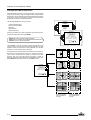
Location and Function of Controls
2
LOCATION AND FUNCTION OF CONTROLS
REAR PANEL TERMINOLOGY
PORT 4/5
(RGB + HV)
Comp/H sync V sync
PORT 6 REMOTE
COMMUNICATION
PORT 3
. .
. . .
R
1
1
2
3
2
G
B
4
3
Communication Port
* Not used.
5
4
- unlit: mains (power) switch is not pressed.
- lit: mains (power) switch is pressed and the indicated
color shows the projector mode:
Green:
operational mode of the projector.
Red:
standby mode of the projector.
Port 3
RGB Analog Input (9 pin female sub D connector): allows a
character generator, microcomputer, etc. having analog
RGB outputs to be connected to the projector.
Important: projector ("Operational" or "Standby") mode is
defined during the installation of the projector. (Refer to a
qualified technician for change).
Port 4/5 RGB-S Input (5x BNC connector):
RGB-S input : allows a character generator, microcomputer,
video camera, etc. having analog RGB output to be connected to the projector.
Line inputs:
- signals RED-GREEN-BLUE
- COMPOSITE sync signal
- Tri level sync signal (option)
Projector Mode: indicates the status of the projector.
5
Power Switch: press the switch to turn the projector ON.
Depending on the hardware set-up of the projector during
installation, the projector will switch to ‘Standby’ or to
‘Operational' mode. If in standby, the standby LED will
light up.
FRONT PANEL TERMINOLOGY
V NOM
1 MAX
FREQ
120/230 Volt
7/5 Amp
50/60Hz
RS232 IN
5
1
2
1
RS232 OUT
2
IR
3
REMOTE
4
RS 232 Input Port
Connection between the projector and an IBM PC (or
compatible) or MAC (RS422) for remote computer control
and data communication.
RS 232 Output Port
RS 232 Output Port allows a communication link for PC or
MAC to the next projector in a series of projector.
3
IR Sensor
Receiver for control signals transmitted from the RCU.
4
IR Remote
Connector for remote input for hard wired remote control
5
AC Power Input
2-1
Location and Function of Controls
Control Panel Terminology
a. The Local Keypad (built in RCU)
Gaining Access
The local keypad is built in into the rear of the projector. Push once
on the door cover and it will open. It is possible to turn it 90°.
This local keyboard has the same functions as the Remote Control
Unit (RCU).
PORT 4/5
(RGB + HV)
Comp/H sync V sync
PORT 6 REMOTE
. .
. . .
PORT 3
COMMUNICATION
R
B
G
b. RCU Control Panel Terminology
This remote control includes a battery powered infrared (IR) transmitter that allows the user to control the projector remotely.
This remote control is used for source selection, control, adaptation
and set-up. It includes automatic storing of :
- picture controls (Brightness, Sharpness…)
- picture geometry adjustments
- convergence adjustments
Other functions of the remote control are:
- switching between standby and operational modes
- switching to "pause" (picture mute)
- direct access to all connected sources
- variable adjustment speed: when pushing continuously on the
control stick or the picture keys, the adjustment will be executed
in an accelerated fashion.
12
11
1
▼
ADJ
EXIT
▼
ENTER
▼
3
STBY
PAUSE
TEXT
▼
4
pause/park
9
Backlight Key: when activated, all keys will be lit up and
visible in the dark.
2
ADJ.: adjust key, to enter or exit the adjustment mode.
3
Address Key (recessed): to enter the address of the projector (between 0 and 9). Press the address key, followed by
pressing one digit button between 0 and 9. When programmed
with address 0, the remote will talk to all projectors regardless
of their address. See page 4-2 on Setting Projector Address.
sharpness
FREEZ
II
8
5
6
10
▼
2
standby
1
9
0
+
–
SHARPNESS
7
8
–
5
6
–
3
4
+
–
BRIGHTNESS
1
2
+
–
CONTRAST
...
TINT
tint
color
4
STBY (standby):
- to initiate remote power up operation
- to put the projector in standby
5
Pause: to mute, press PAUSE. The image will disappear
but full power will be retained for immediate restarting.
6
Digit Buttons: direct aspect ratio selection.
7
Picture Controls: use these buttons to obtain the desired
level (see also 'Controlling') for each picture function.
7
+
brightness
..
+
COLOR
contrast
8
11
9
ENTER: to start up the adjustment mode or to confirm an
adjustment or selection in the adjustment mode.
10
EXIT: to leave the adjustment mode or to scroll upwards
when in the adjustment mode.
12
2-2
TEXT: when adjusting one of the image controls during a
meeting, the displayed bar scale can be removed by
pressing 'TEXT' key first. To re-display the bar scale on the
screen, press 'TEXT' key again. 'TEXT' key is only active in
the operational mode. When 'TEXT' is off, no warning
message will be displayed.
Control Disk: to make menu selections when in the adjustment mode. Also allows to increment or decrement an
adjustment in the adjustment mode.
control disk up = up arrow in the menus
control disk down = down arrow in the menus
control disk to the right = arrow to the right on the menus
control disk to the left = arrow to the left on the menus
RC Operating Indication: lights up when a button on the
remote control is pressed. (This is a visual indicator to check
the operation of the remote control)
Connections
3
CONNECTIONS
AC Power (mains) Cord Connection
Use the supplied power cord to connect your projector
to the wall outlet. Plug the female power connector into
the male connector at the front side of the projector.
V NOM
1 MAX
FREQ
120/230 Volt
7/5 Amp
50/60Hz
RS232 IN
RS232 OUT
IR
REMOTE
Power Check
Power voltage indication is on the sticker on the rear side of the
projector. The power voltage is indicated by the serial number sticker.
Warning !
Check if the indicated power voltage corresponds to that of the wall
outlet.
If the wall outlet voltage is different, call a qualified technician for
power adaptation of the projector.
Switching On/Off
The main power to the projector is switched ON and OFF using the
power (mains) switch ON/OFF.
Pressed: ON
Not pressed: OFF
The projector can start now in the 'operational mode' (image displayed) or in the 'standby mode', depending on the position of the
'power up' dip switch on the controller unit. This DIP switch must be
set during installation by a qualified technician. If you want to change
this startup mode, call a qualified technician.
Standby indication lamp:
no light: projector switched off
green color: projector in Operational mode
red color: projector is in Standby mode
When starting up the projector with the power switch or via the standby key, the projector can start up in two ways if the "CRT Run in Cycle"
option is switched OFF:
- full white image (projector warm up) or
- immediately image display.
Your choice of starting can be set in the Service Mode.
3-1
Connections
Start Up with Full White Image.
If no action is taken, a white image will be displayed for 20 minutes.
This white image will be shifted on the faceplate of the CRT to avoid
a CRT burn in. During this warm-up period, it is possible to interrupt
this white image projection by pressing the EXIT key.
If EXIT is pressed, the remaining warm-up period will be skipped.
During the warm-up period, every 30 seconds a text box with the
remaining time will be displayed on the screen for 2 seconds. This text
box will be displayed every time in another place.
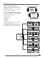
Signal Input Connection to the Projector
PORT 4/5
(RGB + HV)
- RGB/Component
PROJECTOR MODE
Comp/H sync V sync
PORT 6 REMOTE
COMMUNICATION
PORT 3
. .
. . .
R
3
G
GREEN: operational
RED: stand-by
B
4
5
Port No
3
4/5
3-2
Projector input
RGB1
RGB/Component
1
Input signal : R, G and B with automatic sync detection
between seperate sync (separate composite sync or
with separate Horizontal and Vertical sync) or sync on
green (composite sync).
Connections
Connecting a RGB Analog Source to Port 3
Connect your RGB source via an interface to Port 3. Always
use an interface when a computer and local monitor have to be
connected to the projector.
PORT 4/5
(RGB + HV)
PROJECTOR MODE
Comp/H sync V sync
Pin configuration D9 connector of the Analog input:
1 not connected
2 ground RGBS
3 RED
4 GREEN
5 BLUE
6 ground RGBS
7 ground RGBS
8 Hor/comp. sync
9 Vert. sync
PORT 6 REMOTE
COMMUNICATION
. .
. . .
PORT 3
R
ON
OFF
B
G
ANALOG INTERF. 120MHz
. . . .
R
G
INPUT
B
H
V
. . . . . .
RGB analog input with automatic sync detection. (Separate H
and V sync inputs, with composite sync input or with sync
signals on green)
GREEN: operational
RED: stand-by
INP
75 Ohm ter m
INP
inver.
Connecting a RGB or Component Source to Port 4/5
RGB analog input terminals with separate H and V sync inputs,
with composite sync input or with sync signals on green
(automatic sync detection), or component (Y, Pb, Pr) sources
from a DTV Decoder, etc.
PORT 4/5
(RGB + HV)
PROJECTOR MODE
Comp/H sync V sync
PORT 6 REMOTE
COMMUNICATION
PORT 3
. .
. . .
R
G
GREEN: operational
RED: stand-by
B
3-3
Connections
Connecting a Component Video Source to
Port 4/5
PORT 4/5
(RGB + HV)
Comp/H sync V sync
PORT 6 REMOTE
COMMUNICATION
PORT 3
. .
. . .
R
A component video source can be connected to the
projector via the Port 4/5. The projector detects
automatically where the sync signal is located.
To select the component video input, select component
from the source selection menu.
HDTV
3-4
G
B
Controlling
4
CONTROLLING
Caution: Do not display a stationary image with full brightness
and contrast for longer than 20 minutes, otherwise you risk
damage to the CRTs.
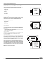
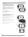
Battery Installation in the RCU
A new battery has been packaged inside the plastic bag with the
power cord. Before using the RCU, install the battery first.
Remove the battery cover on the backside of the RCU by pushing the
indicated handle a little to the bottom of the RCU. Lift the top side of
the cover at the same time (fig. 1).
Insert the new 9V battery (type 6F22S or equivalent; alkaline batteries
are recommended) in the lower compartment and connect the battery
to the contact plate.
Insert the battery into the lower compartment and put the cover back.
Insert here
(behind the
plastic cover)
the 'Insert card
for RCU'.
Contact
plate
fig.1
Battery
fig.2
310a.DRW
4-1
Controlling
Projector Address
The Runco DTV-1101 can be controlled with
a. the RCU
b. the built-in RCU (local keypad)
a. Software set up of the projector address
The procedure and results of controlling the projector with either of
these RCU options is essentially the same.
See 'Change Projector Address' in Chapter 2, 'Service Mode'.
Every projector requires an individual address between 0 and 255,
which is set in the Service mode. Only projectors with addresses
between 0 and 9 can be controlled with the RCU.
How to Use Your RCU
b. How to control the projector
a) Point the front of the RCU towards the reflective screen surface.
b) Point the front of the RCU towards one of the IR sensors in the
projector.
When using the wireless remote control, make sure you are within the
effective operating distance (30m, 100ft in a straight line). The remote
control unit will not function properly if strong light strikes the sensor
window or if there are obstacles between the remote control unit and
the projector's IR sensor.
The projector's address may be set to any value between 0 and 255.
When the address is set, the projector can be controlled with:
- the RCU for addresses between 1 and 9.
- computer, e.g. IBM PC (or compatible), Apple MAC, etc. for
addresses between 0 and 255.
Note: Address '0' is a universal address. A projector will respond to
an RCU set to an address of '0' regardless of what address is set in
the projector itself.
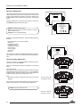
c. Using Your RCU
Before using your RCU, it is necessary to enter the projector address
into the RCU (only when that address is between 1 and 9). The
projector with the corresponding address will listen to that specific
RCU.
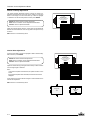
IR Receiver Locations on the Projector:
When address '0' (zero address) is programmed into the RCU, every
projector - without exception - will listen to the commands given by this
RCU.
0
7
7
5
6
3
4
1
2
5
6
3
4
2
365
4-2
Controlling
How to Display a Projector Address
Analog Picture Controls
Press the ADDRESS key (recessed key on the RCU) with a pencil.
The projector's address will be displayed in a 'text box'. This text box
will disappear after a few seconds.
The analog picture controls can be adjusted with the RCU. The control
keys are located on the lower right side of the key panel of the RCU
and indicated with the name of the control and an icon.
To continue using your RCU, it is necessary to enter the same address
with the digit buttons (address between 0 and 9). For example, if the
Address Key displays projector address 003, then press the '3' digit
button on the RCU to set the RCU's address to match the projector's
address.
When an analog picture control is pressed, a text box with bar scale
and the function name of the control, e.g. 'brightness...' appears on the
screen (only if 'TEXT' is on). The length of the bar scale indicates the
current memorized setting for this source. The bar scale changes as
the + or - buttons of the control are pressed.
How to Program an Address into the RCU
Brightness Control
Press the ADDRESS key (recessed key on the RCU) with a pencil and
enter the address with the digit buttons. This address can be any digit
between 0 and 9.
A correct 'brightness' setting is important for good image reproduction. Adjust the brightness with the + button and - button (RCU) until
the darkest parts of the picture appear black.
When programming '0' (zero address), the RCU will control a projector
regardless of the projector's address. This feature allows multiple
projectors with different addresses to be controlled by a single RCU.
A bar scale gives a visual indication on the screen of the current
brightness setting while pressing on the above indicated keys. If the
bar scale is not visible on the screen, press the 'TEXT' key once and
retry the keys indicated above. The bar scale will increase when
pressing on the + button (higher brightness) and will decrease when
pressing on the - button (lower brightness).
Input Selection
To select an input (source), press ADJ on the remote control, then
highlight SOURCE SELECTION and press enter. Then, highlight
the desired source and press enter.
Contrast Control
When a valid and available source is selected, there will be information displayed on the screen about that source (if 'Text' is on). This
information includes:
- source number
- horizontal frequency
- vertical frequency
A bar scale gives a visual indication on the screen of the current
contrast setting while pressing the + or - buttons (RCU). If the bar
scale is not visible on the screen, press the 'TEXT' key once and retry
the keys indicated above. The bar scale will increase when pressing
on the + button (higher contrast) and will decrease when pressing on
the - button (lower contrast).
A correct 'contrast' setting is important for good image reproduction.
Adjust the contrast to the level you prefer, according to room lighting
conditions. If the Contrast Control is too low, the picture will be too dim.
If it is set too high, the picture may be too bright and not sharp.
When the entry is a non-valid source number, a warning appears on
the screen: 'input not available'. When a valid source number is
selected, the projector will display this source or it will wait until the
source becomes available. A message 'source not available' will be
displayed for a short time.
4-3
Controlling
Controlling Chained Projectors
Projectors can be controlled individually as well as in a group.
For individual control, see previous pages.
For group control of the projectors, see Input Selection and Analog
Picture Control.
Program the 'zero address' into any RCU. Press on the address key
and key in the address ('0') with the numeric keys on the RCU itself.
Once address '0' is pressed, all projectors will be controlled together
until a new address is entered on the RCU. It is possible to have a
common input selection and a common analog picture control. Once
a new address is entered, only the projector with that specific address
will follow the new instructions.
4-4
Start Up of the Adjustment Mode
5
START UP OF THE ADJUSTMENT MODE
Adjustment Mode
All picture geometry and convergence adjustments are made while in
the 'Adjustment Mode'. Press the ADJUST key to enter the 'Adjustment
Mode'.
Enter the digits with the numeric keys on the RCU.
You are now in the 'Adjustment mode'. The Control disk is used to
make menu selections and also vertical and horizontal adjustments.
The ENTER and EXIT keys are used to move forward and backward
through the menu structure. The ADJUST key can be used to
terminate the adjustment mode while any path selection menu is
displayed.
For each digit entered, a 'X' will appear on the screen under the
displayed text 'enter password'. When your password is correct, you
will have access to the 'Adjustment item'. When the entered password
is wrong, the message 'Wrong password !!!' will be displayed. The
projector will stay on the previously selected item.
Example: 2 3 1 9
Factory programmed password:
When an adjustment menu is displayed on the screen and no action
is taken within the first 5 minutes, the projector will automatically
reduce the brightness and contrast to a level so that the stationary
image cannot damage the tubes.
There are 6 possible paths to follow once in the 'Adjustment Mode.'
They are :
0000
Once the password is correctly entered, all other password protected
items are accessible without re-entering your password. When reentering the Adjustment Mode, it will be necessary to enter your
password again when selecting a password protected item.
SOURCE SELECTION - Provides the selection of either RGB,
Component, RGB Tri-level or Component Tri-level sources.
INSTALLATION - Installation should be selected if the projector has
been relocated and/or a different screen size is desired. When
selecting 'Installation', the user or operator will be warned to call a
qualified technician to perform the installation procedure (see example of projected warning on the next page).
GUIDED - Guided should be selected if the user intends to perform a
complete alignment of the projected image. All of the necessary
geometry and convergence adjustments are made in a predetermined sequence.
RANDOM ACCESS - Random Access should be selected if the user
intends to make only a few adjustments.
SERVICE - Service should be selected if the user intends to delete
blocks, change password, select service adjustments, or get set-up
information.
EYE-Q - This selection will access the EYE-Q menu.
While in Guided or Random Access Adjustment Modes, the user may
use an external source, an internally generated genlocked pattern, or
an internally generated multifrequency cross hatch pattern as a setup
pattern.
Warning during the start up of the installation mode
Some items in the Adjustment Mode are password protected. While
selecting such an item, the projector asks you to enter your password.
(Password protection is only available when the password DIP switch
on the controller module is in the ON position. Contact a Runco
authorized technician when no password is requested during the
adjustment procedure and password protection is desired.)
Your password contains 4 digits.
5-1
Random Access Adjustment Mode
6
RANDOM ACCESS ADJUSTMENT MODE
ADJUSTMENT MODE
Select a path from below :
Starting Up the Random Access Adjustment Mode
SOURCE SELECTION
ADJUSTMENT MODE
EYE Q
Push the control disk up or down to highlight "RANDOM ACCESS" and
then press ENTER.
Some items in the Random Access Mode are password protected
(when the password function is enabled). Enter your password to
continue. All other password protected items are now also available if
you stay in the Adjustment Mode.
ADJUSTMENT MODE
Select a path from below :
ENTER continues to Setup Pattern Selection
EXIT returns to Operational Mode
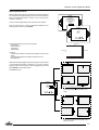
Overview 'Random Access Adjustment' Mode
COLOR BALANCE
SYNC
GUIDED
RANDOM ACCESS
INSTALLATION
SERVICE
EYE-Q
Source 01
Select with
or
then <ENTER>
<EXIT> to return
PICTURE TUNING
PEAKING
CLAMP TUNING
H PHASE
RASTER SHIFT
RANDOM ACCESS
ADJUSTMENT MODE
V CENTERLINE BOW
GEOMETRY
V CENTERLINE SKEW
LEFT-RIGHT (E-W)
SIDE BOW
SIDE KEYSTONE
SETUP PATTERN SELECTION
SEAGULL CORRECTION
LEFT KEYSTONE
LEFT SIDE CORRECTIONS
LEFT BOW
H CENTERLINE BOW
H CENTERLINE SKEW
TOP KEYSTONE
TOP-BOTTOM (N-S)
TOP BOW
BOTTOM KEYSTONE
BOTTOM BOW
SEAGULL CORRECTION
To next page
To next page
6-1
Random Access Adjustment Mode
From previous page
From previous page
H SIZE
V LINEARITY
V SIZE
TOP
BOTTOM
BLANKING
LEFT
RIGHT
GREEN ONLY
RANDOM ACCESS
ADJUSTMENT MODE
CONVERGENCE
RED ON GREEN
BLUE ON GREEN
RED
SETUP PATTERN SELECTION
FOCUSING
GREEN
BLUE
RED
GREEN
BLUE
COLOR SELECT
RED AND GREEN
BLUE AND GREEN
RED AND BLUE
6-2
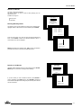
Random Access Adjustment Mode
Selecting Setup Pattern
If an external source is connected to the projector, this menu will be
displayed. Push the control disk up or down to highlight the desired
setup pattern and then press ENTER.
Genlocked pattern: internally generated crosshatch pattern, based
on the scan rate of the external source.
Choose a setup pattern
from below :
SELECTED SOURCE
GENLOCKED PATTERN
INTERNAL # PATTERN
Source 01
Internal # pattern: internally generated crosshatch pattern and locked
on internal generated sync signals (no external source necessary).
ENTER continues to Random Access Adjustment Mode or Internal #
Pattern Selection.
Select with
or
then <ENTER>
<EXIT> to return
EXIT returns to Path Selection Menu
ADJUST returns to Operational Mode
If no external source is connected to the projector, the Internal
Crosshatch Pattern Menu will be displayed.
Note: The menus in this manual are created to demonstrate when an
external source is connected to one of the inputs and when the 'Genlocked
Pattern' is selected.
INTERNAL # PATTERN
Internal Crosshatch Pattern
The Internal # Pattern Menu will be displayed if the Internal Crosshatch
Pattern has been selected or if no source is connected to the projector.
The table below lists the 8 fixed factory preset frequencies available.
Another 8 blocks are custom programmable.
kHz / Hz
15.6/50
15.7/60
31.2/50
31.5/60
31.2/50
31.5/60
PAL/SECAM
NTSC
EDTV
IDTV
HDTV EUREKA
HDTV ATV
Select with
or
scroll with
or
<ENTER> to accept
<EXIT> to return
Push the control disk up or down to highlight the desired crosshatch
frequency. Push the control disk to the left and to the right to scroll to
another page. Press ENTER if the desired block is selected.
kHz/Hz
15.6/50
15.7/60
31.2/50
31.5/60
31.2/50
31.5/60
33.7/60
15.8/60
61.0/76
35.5/87
48.5/60
44.2/70
61.0/76
72.1/67
PAL/SECAM
NTSC
EDTV
IDTV
HDTV EUREKA
HDTV ATV
HDTV HIVISION
EGA 1
VGA 1,2
VGA 4
SUPER VGA 1
SUPER VGA 2
SUPER VGA 3
SUPER VGA 4
ENTER continues to the Random Access Adjustment Mode
EXIT returns to the Setup Pattern Selection Menu
6-3
Random Access Adjustment Mode
Random Access Adjustment Mode Selection Menu
This is the main menu for the Random Access Adjustment Mode.
Through this menu, the following adjustments and features are accessible:
- Picture Tuning
Sync Slow/Fast
Color Balance
- Focusing
- Geometry
- Convergence
- Color Select
RANDOM ACCESS
ADJUSTMENT MODE
PICTURE TUNING
GEOMETRY
CONVERGENCE
FOCUSING
COLOR SELECT
Select with
or
then <ENTER>
<EXIT> to return
Picture Tuning
Highlight Picture Tuning by pushing the control disk up or down and press
ENTER. The Picture Tuning Menu will be displayed. Depending on the
input source, the Picture Tuning Menu will display different items.
For RGB and Component sources:
Color Balance
Sync Slow/Fast
Peaking
Clamp Tuning
PICTURE TUNING
COLOR BALANCE
SYNC : FAST
PEAKING
CLAMP TUNING
Color Balance
The Color Balance function is used to select or adjust the color temperature
of white used by the projector. The Color Balance can be adjusted in two
different ways:
- Fixed color balance. You have the choice between 3200 K (reddish),
5400 K, 6500 K (white) or 9300 K (bluish).
- Custom white and black balance.
Select with
or
<ENTER> to accept
<EXIT> to return
Fixed Color Balance
Highlight one of the 4 preprogrammed color temperatures with the control
disk and press ENTER to display the desired color balance.
Custom Color Balance
Select Custom Red & Blue Gain with the control disk and press ENTER to
start the adjustment. Push the control disk up or down to adjust theRed Gain
and push the control disk to the left or to the right to adjust the Blue Gain.
A bar scale indicates the amount of adjustment. Select custom Green Gain
with the control disk and press ENTER to start the adjustment. Push the
control disk up or down to adjust the Green Gain.
Select Custom Red & Blue Cut-off with the control disk and press enter to
start the adjustment. Push the control disk up or down to adjust the Red
Cut-off and push the control disk to the left or to the right to adjust the Blue
Cut-off. Select custom Green Cut-off with the control disk and press enter
to start the adjustment. Push the control disk up or down to adjust the Red
Cut-off.
EXIT returns to the Picture Tuning Menu.
6-4
PICTURE TUNING
COLOR BALANCE
SYNC : FAST
PEAKING
CLAMP TUNING
Select with
or
<ENTER> to accept
COLOR BALANCE
<EXIT> to return.
FIXED COLOR BALANCE
3200 5400 6500 9300
CUSTOM RED & BLUE GAIN
CUSTOM GREEN GAIN
CUSTOM RED & BLUE CUT OFF
CUSTOM GREEN CUT OFF
Select with arrow keys
then <ENTER>
Red & Blue :
adjust red with
or
Blue with
or
<EXIT> to return
Random Access Adjustment Mode
Sync Fast/Slow Adjustment
The sync function is used to minimize horizontal jittering or tearing at
the top to the displayed image. Highlight SYNC by pushing the control
disk up or down and press ENTER to toggle between FAST and
SLOW.
Note: SYNC is normally used in the SLOW position.
PICTURE TUNING
COLOR BALANCE
SYNC : FAST
PEAKING
CLAMP TUNING : normal
ENTER will toggle Sync between FAST and SLOW
EXIT will return to the Random Access Adjustment Menu
Select with
or
<ENTER> to accept
<EXIT> to return
Peaking
Peaking improves the contours in an projected image. Highlight
PEAKING by pushing the control disk up or down and press ENTER
to display the Peaking Menu.
PICTURE TUNING
During the creation of new settings for a RGB source, the corresponding peaking is switched on as default. For frequencies between :
15 kHz — 45 kHz: Low frequency peaking
45 kHz — 85 kHz: Mid frequency peaking
85 kHz — 135 kHz: High frequency peaking
If another peaking is desired, use the control disk to highlight 'low',
'mid', or 'high' frequency or to switch off the peaking.
COLOR BALANCE
SYNC : FAST
PEAKING
CLAMP TUNING : normal
Select with
or
<ENTER> to accept
<EXIT> to return.
PEAKING
OFF
LOW FREQUENCY
MID FREQUENCY
HIGH FREQUENCY
Select with
or
then <ENTER>
<EXIT> to return
Clamp Tuning
Highlight CLAMP TUNING by pushing the control disk up or down and
press ENTER to toggle between NORMAL and RESTORATION.
Select Normal: - for all standard sources and all sources with a
backporch > 0.8µs
- for sources with noise and spikes in the signal
Select Restoration:
- for standard sources with a backporch between
0.4 µs and 0.8 µs
- for sources with sync separate or sync on Green
PICTURE TUNING
COLOR BALANCE
SYNC : FAST
PEAKING
CLAMP TUNING: normal
Select with
or
<ENTER> to accept
<EXIT> to return
6-5
Random Access Adjustment Mode
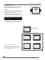
Color Select
Highlight COLOR SELECT by pushing the control disk up or down
and press ENTER to display the Color Select Menu.
ENTER continues to the Color Select Menu
EXIT will return to Internal Crosshatch Selection or Setup Pattern
Selection Menu
ADJUST returns to Operational Mode
Use the control disk to highlight a color (CRT) or combination of colors
to display the projected image in that specific color. To select a new
color, press ENTER. The Color Selection Menu will appear again on
the screen. To terminate the color select procedure, press EXIT.
RANDOM ACCESS
ADJUSTMENT MODE
PICTURE TUNING
GEOMETRY
CONVERGENCE
FOCUSING
COLOR SELECT
Select with
or
then <ENTER>
<EXIT> to return.
COLOR SELECT
RED
GREEN
BLUE
RED AND GREEN
BLUE AND GREEN
RED AND BLUE
Select with
or
<ENTER> to accept
<EXIT> to return
ENTER continues with the selected color or color combination
EXIT returns to the Random Access Main Menu
6-6
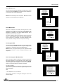
Random Access Adjustment Mode
Focusing
Before starting the focusing adjustment, be sure the lenses are
correctly focused. Push the control disk up or down to select FOCUSING
and press ENTER.
RANDOM ACCESS
ADJUSTMENT MODE
PICTURE TUNING
GEOMETRY
CONVERGENCE
FOCUSING
COLOR SELECT
ENTER continues to the Focusing (Color Select) Menu.
EXIT returns to Internal Crosshatch Selection or Setup Pattern
Selection Menu.
Select with
or
then <ENTER>
<EXIT> to return.
FOCUSING
ADJUST returns to Operational Mode.
RED
GREEN
BLUE
Focusing Color Select
BLUE ON SOURCE
The focusing has to be done for the three colors separately. Therefore,
start by selecting Green by pushing the control disk up or down and
adjust Midpoint, Top, Bottom, Left, and Right Focusing. Return to this
Focusing (Color Select) Menu and continue with Red and Blue.
Repeat for both colors Midpoint, Top, Bottom, Left, and Right focusing.
Select with
or
then <ENTER>
<EXIT> to return
ENTER selects the Focusing Menu for the selected color.
EXIT returns to the Random Access Main Menu.
Midpoint Focusing
Push the control disk up or down to select midpoint and press ENTER
continue with the midpoint focusing. Adjust by pushing the control disk
to the left or to the right until the center of the image is sharp. Press
ENTER to return to the Focusing Menu.
FOCUSING
RED
GREEN
BLUE
Top Image Focusing
BLUE ON SOURCE
The same procedure has to be repeated as for the midpoint focusing.
Push the control disk up or down and press ENTER to continue to the
top focusing. Push the control disk to the left or to the right to adjust
the top focusing. Adjust until the upper part of the image is sharp.
ENTER to return to the Green Focusing Menu.
Select with
or
then <ENTER> GREEN FOCUSING
<EXIT> to return.
MIDPOINT
TOP
BOTTOM
LEFT
RIGHT
Bottom Image Focusing
Select with
or
then <ENTER>
<EXIT> to return
The same procedure has to be repeated as for the midpoint focusing.
Push the control disk up or down to select bottom and press ENTER
to continue to the bottom focusing. Push the control disk up or down
to adjust the bottom focusing. Adjust until the lower part of the image
is sharp. ENTER to return to the Green Focusing Menu.
Left Image Focusing
The same procedure has to be repeated as for the midpoint focusing.
Push the control disk up or down to select LEFT and press ENTER to
continue to the left focusing. Push the control disk up or down to adjust
the left focusing. Adjust until the left part of the image is sharp. ENTER
to return to the Green Focusing Menu.
Right Image Focusing
The same procedure has to be repeated as for the midpoint focusing.
Push the control disk up or down to select RIGHT and press ENTER
to continue to the right focusing. Push the control disk to the left or to
the right to adjust the right focusing. Adjust until the right part of the
image is sharp. ENTER to return to the Green Focusing Menu. When
on the Green Focusing Menu, press EXIT to return to the Focusing
(Color Select) Menu and continue with the other colors.
Blue on Source
If after focusing the three colors a discoloring on a normal image is still
visible, select 'Blue On Source' on the Focusing Menu and repeat the
above steps for Midpoint, Top, Bottom, Left, and Right focusing.
Press EXIT to return to Focusing Menu.
6-7
Random Access Adjustment Mode
Geometry Adjustments
The geometry adjustments have to be done only on the green image.
These adjustments are automatically implemented for the other color
images: Left-right (EW) and Top-Bottom Corrections, Blanking, Horizontal Amplitude, Vertical Amplitude, Vertical Linearity, and Horizontal
Phase.
RANDOM ACCESS
ADJUSTMENT MODE
PICTURE TUNING
GEOMETRY
CONVERGENCE
FOCUSING
COLOR SELECT
Highlight GEOMETRY by pushing the control disk up or down and
press ENTER to display the Geometry Menu.
Select with
or
then <ENTER>
<EXIT> to return.
GEOMETRY
H PHASE
RASTER SHIFT
LEFT-RIGHT (E-W)
LEFT SIDE CORRECTION
TOP-BOTTOM (N-S)
H SIZE
V LINEARITY
V SIZE
BLANKING
ENTER will display Geometry Menu
EXIT will return to Internal Crosshatch Selection or Setup
Pattern Selection Menu
ADJUST returns to Operational Mode
Select with
or
then <ENTER>
<EXIT> to return
Within the Geometry Adjustment Menu, the following adjustments are
available:
- Horizontal Phase (not for internal # pattern)
- Raster Shift
- Left-Right Corrections
- Left Side Corrections
- Top-Bottom Corrections
- Horizontal Size
- Vertical Linearity
- Vertical Size
- Blanking
GEOMETRY
H PHASE
RASTER SHIFT
LEFT-RIGHT (E-W)
LEFT SIDE CORRECTION
TOP-BOTTOM (N-S)
H SIZE
V LINEARITY
V SIZE
BLANKING
The convergence corrections are disabled during geometry corrections.
The blanking corrections are only enabled during the blanking adjustments.
Select with
or
then <ENTER>
<EXIT> to return.
Horizontal Phase Adjustment
Push the control disk up or down to highlight H PHASE on the Geometry Menu and then press ENTER.
H PHASE
Note: No horizontal phase adjustment is available on the internal #
pattern.
70
For external sources:
If the raster shift is correctly adjusted, the H Phase text box is projected
in the middle of the raster. At that moment, the "><" icon indicates the
middle of the raster. Adjust the H Phase control until the middle of the
projected image is equal with the middle of the >< icon.
Note:
- if the genlocked pattern was selected, the external source will be
displayed.
Push the control disk
to the right to correct
H PHASE
70
A bar scale and a number indicator (between 0 and 100) on the screen
will give a visual indication of the horizontal phase adjustment.
ENTER continues to Geometry Menu
Push the control disk
to the left to correct
H PHASE
70
6-8
Random Access Adjustment Mode
Raster Shift Adjustment
The green raster must be centered both horizontally and vertically on
the center of the CRT surface. To center the green raster, look into the
green lens and use the control disk to move the raster.
CAUTION:
It is necessary to look into the lenses to perform these adjustments.
To avoid eye discomfort while looking into the lenses, reduce the
contrast and gradually increase the brightness level until the raster
becomes visible on the face of the CRT.
GEOMETRY
H PHASE
RASTER SHIFT
LEFT-RIGHT (E-W)
LEFT SIDE CORRECTION
TOP-BOTTOM (N-S)
H SIZE
V LINEARITY
V SIZE
BLANKING
Select with
or
then <ENTER>
<EXIT> to return
ENTER will select Green Raster Shift Adjustment
EXIT returns to Random Access Adjustment Mode Menu
Warning: In order to ensure maximum CRT longevity and to
avoid CRT damage, do not shift the raster outside the phosphor area of the CRT.
To start the adjustment, use the control disk to highlight Raster Shift
and press ENTER to display the green raster on the phosphor.
Press EXIT to return to the Geometry Menu.
Note: Horizontal and Vertical shifts for Red and Blue should
end up with a setting close to 50%. If these settings are
significantly greater or lesser than 50%, then contact a
Runco authorized service technician.
233
6-9
Random Access Adjustment Mode
Left-Right (East-West) Adjustments
Left-right adjustments affect only the vertical lines of the projected
image. Only the green image is displayed while making left-right
adjustments. The red and blue images will automatically be corrected
in the same manner. Convergence corrections are automatically
disabled for the duration of these adjustments.
The following adjustments can be executed:
GEOMETRY
H PHASE
RASTER SHIFT
LEFT-RIGHT (E-W)
LEFT SIDE CORRECTION
TOP-BOTTOM (N-S)
H SIZE
V LINEARITY
V SIZE
BLANKING
- Vertical Centerline Bow
- Vertical Centerline Skew
- Side Bow
- Side Keystone
- Seagull Correction
Push the control disk up or down to highlight LEFT-RIGHT (E/W) on
the Geometry Menu and then press ENTER.
ENTER will select Left-Right Adjustment Menu
EXIT returns to Random Access Adjustment Mode Main Menu.
ADJUST returns to Operational Mode
Select with
or
then <ENTER>
<EXIT> to return.
LEFT-RIGHT
V CENTERLINE BOW
V CENTERLINE SKEW
SIDE BOW
SIDE KEYSTONE
SEAGULL CORRECTION
Warning : Use this correction to
adjust the right side of the image !
Select with
or
then <ENTER>
<EXIT> to return
The WARNING: "Use this correction to adjust the right side of the
image" appears on the screen when selecting 'Side Bow' or 'Side
Keystone'. When the right side is correctly adjusted, use 'Left Side
Correction' to correct the left side of the image.
All adjustments are indicated on the screen with the function name, a
bar scale and a number between 0 and 100. Adjust the next alignments until the vertical lines are straight. For side bow and side
keystone, look only to the right side of the image. To enter an
alignment, push the control disk up or down to highlight a function and
press ENTER to activate this function. Press EXIT to return.
Corrects for curvature of the vertical lines in the middle
of the image.
LEFT-RIGHT
V CENTERLINE BOW
V CENTERLINE SKEW
SIDE BOW
SIDE KEYSTONE
SEAGULL CORRECTION
Corrects the tilting of the vertical lines in the middle of
the image.
Select with
or
then <ENTER>
<EXIT> to return
Corrects for curvature of the vertical lines on the right side
of the image.
Corrects the keystone geometry correction of the vertical
lines on the right side of the image.
Correct by pushing
the control disk to
the right
6-10
Correct by pushing
the control disk to
the left
Random Access Adjustment Mode
Seagull Correction
Use this correction only if, after adjusting the vertical lines with the side
bow or side keystone, an 'S' deformation is still visible on the left and
the right side of the image. The default value on the bar scale for this
correction is 50.
Push the control disk up or down to highlight SEAGULL CORRECTION on the Left-Right Menu and then press ENTER.
GEOMETRY
H PHASE
RASTER SHIFT
LEFT-RIGHT (E-W)
LEFT SIDE CORRECTION
TOP-BOTTOM (N-S)
H SIZE
V LINEARITY
V SIZE
BLANKING
Select with
or
then <ENTER>
<EXIT> to return. LEFT-RIGHT
Eliminate the deformation by pushing the control disk to the left or to
the right until a straight line is obtained.
V CENTERLINE BOW
V CENTERLINE SKEW
SIDE BOW
SIDE KEYSTONE
SEAGULL CORRECTION
Left Side Correction
Select with
or
then <ENTER>
<EXIT> to return
Left side corrections affect only the vertical lines of the set up pattern.
Only the green image is displayed while making the left side adjustments. The red and blue images will automatically be corrected in the
same manner.
Convergence corrections are automatically disabled for the duration
of these adjustments.
Look only to the left side of the image while adjusting these fine tunings
(bow and keystone). Before starting the left side correction,
ensure that the side bow and keystone adjustments are done
prior to these fine adjustments!
The following adjustments can be executed:
- Left keystone
- Left bow
GEOMETRY
H PHASE
RASTER SHIFT
LEFT-RIGHT (E-W)
LEFT SIDE CORRECTION
TOP-BOTTOM (N-S)
H SIZE
V LINEARITY
V SIZE
BLANKING
Select with
or
then <ENTER>
<EXIT> to return.
LEFT SIDE CORRECTION
Push the control disk up or down to highlight LEFT SIDE CORRECTION on the Geometry Menu and then press ENTER.
LEFT KEYSTONE
LEFT BOW
Ensure that the side bow and
keystone adjustments are done
prior to these fine adjustments!
ENTER will select the Left Side Correction Menu.
EXIT will return to the Random Access Adjustment Menu.
ADJUST returns to Operational Mode.
Select with
or
then <ENTER>
<EXIT> to return
All adjustments are indicated on the screen with the function name, a
bar scale, and a number between 0 and 100. Adjust the next
alignments until the vertical lines on the left side are straight.
LEFT SIDE CORRECTION
LEFT KEYSTONE
LEFT BOW
Ensure that the side bow and
keystone adjustments are done
prior to these fine adjustments!
Correct the keystone geometry distortion of the
vertical lines
Select with
or
then <ENTER>
<EXIT> to return
To enter an alignment, push the control disk up or down to highlight
a function and press ENTER to activate this function. Press EXIT to
return.
Correct the bow geometry distortion of the
vertical lines
Correct by pushing
the control disk to
the right
Correct by pushing
the control disk to
the left
6-11
Random Access Adjustment Mode
Top-Bottom (North-South) Adjustments
Top-Bottom and center adjustments affect only the horizontal lines of
the projected image. To start up the Top-Bottom and center corrections, follow the next procedure:
Push the control disc up or down to highlight TOP-BOTTOM (N/S) on
the Geometry Menu and then press ENTER.
Only the green image is displayed while making top-botton adjustments. The red and blue images will automatically be corrected in the
same manner. Convergence corrections are automatically disabled
for the duration of these adjustments.
The following adjustments can be executed:
GEOMETRY
H PHASE
RASTER SHIFT
LEFT-RIGHT (E-W)
LEFT SIDE CORRECTION
TOP-BOTTOM (N-S)
H SIZE
V LINEARITY
V SIZE
BLANKING
Select with
or
then <ENTER>
<EXIT> to TOP-BOTTOM
return.
(N-S)
H CENTERLINE BOW
H CENTERLINE SKEW
TOP KEYSTONE
TOP BOW
BOTTOM KEYSTONE
BOTTOM BOW
SEAGULL CORRECTION
Select with
or
then <ENTER>
<EXIT> to return
- horizontal centerline bow
- horizontal centerline skew
- top bow
- top keystone
- bottom bow
- bottom keystone
- seagull correction
All adjustments are indicated on the screen with the function name, a
bar scale, and a number between 0 and 100.
Adjust the next alignments until the vertical lines are straight. To enter
an alignment, push the control disk up or down to highlight a function
and press ENTER to activate this function. Press EXIT to return.
Corrects for curvature of the horizontal lines in the
middle of the image.
Corrects the tilting of the horizontal lines in the middle
of the image.
TOP-BOTTOM
H CENTERLINE BOW
H CENTERLINE SKEW
TOP BOW
TOP KEYSTONE
BOTTOM BOW
BOTTOM KEYSTONE
SEAGULL CORRECTION
Corrects for curvature of the horizontal lines on the upper
side of the image.
Select with
or
then <ENTER>
<EXIT> to return
Corrects the keystone geometry correction of the horizontal
lines on the upper side of the image.
Corrects for curvature of the horizontal lines on the lower
side
Corrects the keystone geometry correction of the horizontal
lines on the lower side of the image.
Correct by pushing
the control disk down
6-12
Correct by pushing
the control disk up
Random Access Adjustment Mode
Seagull Correction
Use this correction after the image has been adjusted with top and
bottom bow and keystone. If a deformation is still visible (like a seagull)
on top and bottom of the image, proceed to the seagull correction.
Due to interaction, it is possible that the top and bottom bow will
have to be readjusted after adjusting the seagull correction to obtain
an improved image. The default value on the bar scale of this
correction is 50.
GEOMETRY
H PHASE
RASTER SHIFT
LEFT-RIGHT (E-W)
LEFT SIDE CORRECTION
TOP-BOTTOM (N-S)
H SIZE
V LINEARITY
V SIZE
BLANKING
Select with
or
then <ENTER>
<EXIT> to return.
TOP-BOTTOM (N-S)
Push the control disk up or down to select the 'Seagull Correction' and
press ENTER to select. Eliminate the deformation by pushing the
control disk upwards or downwards until a straight line is obtained.
ENTER will return to Top-Bottom Adjustment Menu. EXIT will return
to Geometry Menu.
H CENTERLINE BOW
H CENTERLINE SKEW
TOP KEYSTONE
TOP BOW
BOTTOM KEYSTONE
BOTTOM BOW
SEAGULL CORRECTION
Select with
or
then <ENTER>
<EXIT> to return
Horizontal Size Adjustment
Push the control disk up or down to highlight H SIZE on the Geometry
Menu and then press ENTER.
ENTER will select horizontal size adjustment
EXIT returns to Random Access Adjustment Mode Menu
ADJUST returns to Operational Mode
GEOMETRY
H PHASE
RASTER SHIFT
LEFT-RIGHT (E-W)
LEFT SIDE CORRECTION
TOP-BOTTOM (N-S)
H SIZE
V LINEARITY
V SIZE
BLANKING
Adjust the horizontal size by the control disk to the right or to the left
until the exact image width is obtained.
Select with
or
then <ENTER>
<EXIT> to return.
Note:
- if the internal # pattern was selected, this pattern remains on the
screen.
- if the genlocked pattern was selected, the external source will be
displayed.
H SIZE
A bar scale and a numeric indicator help to gauge the horizontal size
adjustment.
70
EXIT will return to the Geometry Menu.
H size too
large
Ideal image width
H size too
small
6-13
Random Access Adjustment Mode
Vertical Linearity Adjustment
The vertical linearity adjustment function corrects for vertical nonlinearities that extend from the center of the image to the top and
bottom of the image. Push the control disk up or down to highlight
V LINEARITY on the Geometry Menu and then press ENTER.
GEOMETRY
H PHASE
RASTER SHIFT
LEFT-RIGHT (E-W)
LEFT SIDE CORRECTION
TOP-BOTTOM (N-S)
H SIZE
V LINEARITY
V SIZE
BLANKING
ENTER will select Vertical Linearity Adjustment
EXIT returns to Random Access Adjustment Mode Menu
ADJUST returns to Operational Mode
Adjust the vertical linearity with the control disk until the distances
between the horizontal lines of the set up pattern are equal from top
to bottom.
EXIT will return to the Geometry Menu.
V LINEARITY
70
Vertical Size Adjustment
Push the control disk up or down to highlight V SIZE on the Geometry
Menu and then press ENTER.
GEOMETRY
H PHASE
RASTER SHIFT
LEFT-RIGHT (E-W)
LEFT SIDE CORRECTION
TOP-BOTTOM (N-S)
H SIZE
V LINEARITY
V SIZE
BLANKING
ENTER will select Vertical Size Adjustment
EXIT returns to Random Access Adjustment Mode Menu
ADJUST returns to Operational Mode
Select with
or
then <ENTER>
<EXIT> to return.
Adjust the vertical size by pushing the control disk up or down until the
correct image height is obtained.
Note :
- if the internal # pattern was selected, this pattern remains on the
screen.
- if the genlocked pattern was selected, the external source will be
displayed.
V SIZE
70
A bar scale and a numeric indicator will give a visual indication of the
vertical size adjustment.
EXIT will return to the Geometry Menu.
Ideal
Image
Hight
6-14
Image too
Tall
Ideal
Image
Hight
Image too
Short
Random Access Adjustment Mode
Blanking Adjustments
Blanking adjustments affect only the edges of the projected image and
are used to frame the projected image on to the screen and to hide or
black out unwanted information (or noise). A 0% on the bar scale
indicates no blanking.
To start up the Blanking adjustments, follow the next procedure:
GEOMETRY
H PHASE
RASTER SHIFT
LEFT-RIGHT (E-W)
LEFT SIDE CORRECTION
TOP-BOTTOM (N-S)
H SIZE
V LINEARITY
V SIZE
BLANKING
Push the control disk up or down to highlight BLANKING on the
Geometry Menu and then press ENTER.
Select with
or
then <ENTER>
<EXIT> to return.
BLANKING
TOP
BOTTOM
LEFT
RIGHT
Select with
or
then <ENTER>
<EXIT> to return
The following blanking corrections are possible:
- top blanking
- bottom blanking
- left blanking
- right blanking
Top blanking
Left blanking
Therefore:
- if the internal # pattern was selected, this pattern remains on the
screen.
- if the genlocked pattern was selected, the external source
will be displayed.
Right blanking
Bottom blanking
Adjust the next blanking alignments until the image is correctly framed
or the unwanted information is blanked out. To enter a blanking
alignment, push the control disk up or down to highlight a function and
press ENTER to activate this function.
Press EXIT to return.
Adjustment of the blanking on the top of the image
BLANKING
TOP
BOTTOM
LEFT
RIGHT
Select with
or
then <ENTER>
<EXIT> to return
Adjustment of the blanking on the bottom of the image
Correct by pushing the control disk up or
down
Adjustment of the blanking on the left side
Adjustment of the blanking on the right side
Correct by pushing the control disk to the
right or to the left
6-15
Random Access Adjustment Mode
Convergence Adjustment
Convergence adjustments affect both the horizontal and vertical lines
of the setup pattern. These adjustments are performed on the red
image while superimposed on the green image and then on the blue
image while superimposed on the green image. Start with the Coarse
Convergence Adjustments and finalise with the Fine Convergence
Adjustments.
RANDOM ACCESS
ADJUSTMENT MODE
PICTURE TUNING
GEOMETRY
CONVERGENCE
FOCUSING
COLOR SELECT
Select with
or
then <ENTER>
<EXIT> to return.
CONVERGENCE
COARSE ADJUSTMENT
RED ON GREEN
BLUE ON GREEN
FINE ADJUSTMENT
GREEN ONLY
RED ON GREEN
BLUE ON GREEN
Select with
or
then <ENTER>
<EXIT> to return
The screen area is divided into 25 areas.
25
23
9
15
17
24
22
8
14
16
5
4
1
2
3
20
18
6
10
12
21
19
7
11
13
Coarse Convergence Adjustment
Highlight 'Red on Green' under the Coarse Convergence item and
press ENTER. The Coarse Convergence menu will be displayed.
The following items are possible:
- Horizontal sides: adjust the vertical lines, within a certain area, on
both sides without influencing the lines on the middle of the image.
- Vertical corners: adjust the horizontal lines in the four corners,
within a certain area, without influencing the middle of the image.
Repeat for 'Blue on Green.'
Horizontal Sides
To make a coarse adjustment of the red or blue vertical lines in zone
3 and 5 simultaneously, Highlight 'Horizontal lines' and press ENTER
to start the adjustment.
Select with
or
then <ENTER>
<EXIT> to return.
CONVERGENCE
COARSE ADJUSTMENT
RED ON GREEN
BLUE ON GREEN
FINE ADJUSTMENT
GREEN ONLY
RED ON GREEN
BLUE ON GREEN
or
SelectSelect
with with
or
then <ENTER>
then <ENTER>
to return.
<EXIT><EXIT>
to return.
COARSE
CONVERGENCE
HORIZONTAL SIDES
VERTICAL CORNERS
Select with
or
then <ENTER>
<EXIT> to return
Select with
or
then <ENTER>
<EXIT>
to return.
COARSE
CONVERGENCE
HORIZONTAL SIDES
VERTICAL CORNERS
Hint :
- look to the end of scan and adjust until the red or the blue vertical
lines are on the green lines or as close as possible to the green
lines.
- during these adjustments, the horizontal convergence adjustments
in zones 2, 3, 4, and 5 will be set to midposition (barscale 50).
6-16
Select with
or
then <ENTER>
<EXIT> to return
Random Access Adjustment Mode
Vertical Corners
To make a coarse adjustment of the red or blue horizontal lines in zone
10, 14, 18, and 22 simultaneously, highlight 'Vertical Corners' and
press ENTER to start the adjustment.
Select with
or
then <ENTER>
<EXIT>
to return.
COARSE
CONVERGENCE
HORIZONTAL SIDES
VERTICAL CORNERS
Select with
or
then <ENTER>
<EXIT> to return
Hint :
- Adjust until the red or the blue horizontal lines are on the green lines
or as close as possible to the green lines.
- During these adjustments, the horizontal convergence adjustments in
zones 10 to 25 will be set to midposition (barscale 50).
Fine Convergence Adjustment
Use these controls after the Coarse Convergence Adjustments to
optimize the convergence of the red and blue image on the green image.
Use the control disk to make horizontal or vertical convergence adjustments in the selected zone and then press ENTER to move the box to
another zone or EXIT to return to the Convergence Menu. ENTER
toggles arrow keys between zone selection and zone adjustment .
EXIT returns to Convergence Menu.
Select with
or
then <ENTER>
<EXIT> to return.
CONVERGENCE
COARSE ADJUSTMENT
RED ON GREEN
BLUE ON GREEN
FINE ADJUSTMENT
GREEN ONLY
RED ON GREEN
BLUE ON GREEN
Select with
or
then <ENTER>
<EXIT> to return.
CONVERGENCE
SEL : select area
using
arrow keys
ADJ : adjust area
using
arrow keys
Toggle between
SEL and ADJ
with <ENTER>
<ENTER> continue
<EXIT> to return
Highlight first 'Green Only' when available with the control disk and
press ENTER to display the Convergence Adjustment Menu. Continue
with red on green and blue on green.
CONVERGE
ADJUSTMENT
70
6-17
Service Mode
7
SERVICE MODE
Starting up the Service Mode
Use the control disk to highlight 'Service' and then press ENTER.
ADJUSTMENT MODE
Some items in the Service Mode are password protected (when the
password function is active). Enter your password to continue. All other
password protected items will now also be available if you stay in the
Adjustment Mode.
ENTER continues to the Service Mode Main Menu.
EXIT returns to the Operational Mode.
The service items are combined in two service menus. To switch from
the first to the second menu or vice versa, push the control disk up or
down to select 'More...'
Select a path from
below :
GUIDED
RANDOM ACCESS
INSTALLATION
SERVICE
EYE-Q
source 1
Select with
or
then <ENTER>
<EXIT> to return.
SERVICE MODE
IDENTIFICATION
COPY A BLOCK
DELETE A BLOCK
DELETE ALL BLOCKS
CHANGE PASSWORD
CHANGE LANGUAGE
RUN TIME
SET TO MIDPOSITION
CONVERGENCE MID
DYNAMIC ASTIGMATISM
MORE...
Select with
or
then <ENTER>
<EXIT> to return
SERVICE MODE
G2 ADJUSTMENT
GAMMA CORRECTIONS
CRT RUN IN CYCLE
PROJECTOR WARM UP
CRT DRIVE MODE
MORE...
Overview Flowchart 'Service' Mode
Select with
or
then <ENTER>
<EXIT> to return
IDENTIFICATION
COPY A BLOCK
DELETE A BLOCK
DELETE ALL BLOCKS
CHANGE PASSWORD
CHANGE LANGUAGE
SERVICE MODE
RUN TIME
G2 ADJUSTMENT
GAMMA CORRECTIONS
CRT RUN IN CYCLE
PROJECTOR WARM UP
CRT DRIVE MODE
MEMORY BANKS
7-1
Service Mode
Identification
Highlight 'Identification' with the control disk and press ENTER.
SERVICE MODE
IDENTIFICATION
COPY A BLOCK
DELETE A BLOCK
DELETE ALL BLOCKS
CHANGE PASSWORD
CHANGE LANGUAGE
RUN TIME
SET TO MIDPOSITION
CONVERGENCE MID
DYNAMIC ASTIGMATISM
The 'Identification' screen gives information concerning:
- projector address, to change the address of your projector,
contact a qualified service technician.
- software version
MORE...
Select with
or
then <ENTER>
<EXIT> to return.
- configuration
possible installations:
* front-ceiling
* front-table
* rear-ceiling
* rear-table
DTV-1101
Proj. address : 001
Soft. Version : 6.00
Config. : Ceiling
Front
Baud Rate PC : 9600
Text : ON
Serial No. : 103589552
- baud rate PC: transfer speed for communication with an IBM PC
(or compatible) or MAC. The baud rate of the projector must be the
same as the baud rate of the connected computer. When there is
a difference, contact a qualified service technician to make the
appropriate changes.
- Text: indicates in operational mode if the bar scale and number
indicator will be displayed and if warnings and failures will be
displayed.
ON: displayed
OFF: not displayed
The status can be changed by pressing the 'TEXT' key once on the
RCU.
- Serial no.: indicates the fabrication number of the projector. This
number can be useful when calling for technical assistance.
Copy a Block
The Copy A Block function copies the settings of a selected block into
the active block. Highlight Copy A Block with the control disk and press
ENTER. ENTER will select the highlighted item.
To copy the settings of a closed block to the block you are working on
(active block), use the control disk to select a block. All existing
settings will be overwritten with the new settings.
Press ENTER to copy the selected block. A confirmation screen will
be displayed.
If you are certain you wish to copy the contents of the selected block
into the active block, press ENTER. EXIT cancels the copy procedure
and returns without copying the block.
SERVICE MODE
IDENTIFICATION
COPY A BLOCK
DELETE A BLOCK
DELETE ALL BLOCKS
CHANGE PASSWORD
CHANGE LANGUAGE
RUN TIME
SET TO MIDPOSITION
CONVERGENCE MID
DYNAMIC ASTIGMATISM
MORE...
Select with
or
then <ENTER>
<EXIT> to return.
Nr. Src
1
1
2
3
3
4
2
5
6
7
8
COPY MODE
Fh Fv
inp
15.6 50
video
31.2 60
RGB3S
15.6 50
intern
31.5 50
RGB3S
33.7 60
intern
conf
FC
RT
FC
FC
FC
Active block nr. 1
Select with
or
<ENTER> to copy
<EXIT> to return.
COPY BLOCK
All settings
in current block
will be overwritten!
<ENTER> to confirm
<EXIT> to cancel
7-2
Service Mode
Deletion of Blocks
This item is password protected.
The delete function is used to clear all data (settings) from an
adjustment block.
A delete can be given:
- block by block
or
- for all blocks
Deleting Block by Block
The delete a block function deletes the settings of a selected block.
Highlight 'Delete A Block' with the control disk and press ENTER.
SERVICE MODE
IDENTIFICATION
COPY A BLOCK
DELETE A BLOCK
DELETE ALL BLOCKS
CHANGE PASSWORD
CHANGE LANGUAGE
RUN TIME
SET TO MIDPOSITION
CONVERGENCE MID
DYNAMIC ASTIGMATISM
MORE...
Nr.
1
2
3
4
5
6
7
8
Src
1
3
2
-
DELETE MODE
Fh Fv
inp
15.6 50
video
31.2 60
RGB3S
15.6 50
intern
31.5 50
RGB3S
33.7 60
intern
conf
FC
RT
FC
FC
FC
Active block nr. 1
Push the control disk up or down to select the desired adjustment
block. Press ENTER to delete the selected adjustment block. A
confirmation menu will be displayed.
Select with
or
<ENTER> to copy
<EXIT> to return. DELETE BLOCK
The selected block
will be deleted!
<ENTER> to confirm
<EXIT> to cancel
ENTER will delete the selected block. EXIT cancels the deletion
procedure and returns to the Service Mode Main Menu.
Deletion of all Blocks
Highlight 'Delete All Blocks' with the control disk and press ENTER.
ENTER gives a confirmation message before deleting.
SERVICE MODE
IDENTIFICATION
COPY A BLOCK
DELETE A BLOCK
DELETE ALL BLOCKS
CHANGE PASSWORD
CHANGE LANGUAGE
RUN TIME
SET TO MIDPOSITION
CONVERGENCE MID
DYNAMIC ASTIGMATISM
MORE...
Select with
or
then <ENTER>
<EXIT> to return. DELETE BLOCK
If you are certain you wish to delete all blocks, press ENTER to
confirm. Otherwise, press EXIT to return. Once ENTER is pressed, all
block headers and adjustment settings are permanently removed and
cannot be restored.
All block
will be deleted!
<ENTER> to confirm
<EXIT> to cancel
7-3
Service Mode
Change Password
This item is password protected. Highlight 'Change Password' with
the control disk and press ENTER.
The current password is displayed. The new password must consist
of 4 digits between 0 and 9. Push the control disk to the left or to the
right to select the digits to be changed. Use the numeric keys to enter
the new digits.
Press ENTER to save the new password. Before saving the new
password, a confirmation screen will be displayed. Press EXIT to
return to the Service Menu without saving the new password.
When the displayed password is correct, press ENTER to save.
If it is not correct, press EXIT to cancel the saving.
SERVICE MODE
IDENTIFICATION
COPY A BLOCK
DELETE A BLOCK
DELETE ALL BLOCKS
CHANGE PASSWORD
CHANGE LANGUAGE
RUN TIME
SET TO MIDPOSITION
CONVERGENCE MID
DYNAMIC ASTIGMATISM
MORE...
Select with
or
then <ENTER>
<EXIT> to return.
PASSWORD
Enter new password :
0000
Use
and
to select,
and reprogram
with numeric keys.
<ENTER> to confirm
<EXIT> to return
CHANGE PASSWORD
Password will be
reprogrammed as xxxx
<ENTER> to confirm
<EXIT> to cancel
Change Language
The 'Change Language' function offers the possibility to change the
language of the screen menus to:
- English
- Spanish
- French
- German
Push the control disk up or down to highlight 'Change Language' and
press ENTER to select the language menu. Push the control disk up
or down to select the desired language and press ENTER to change
the language.
SERVICE MODE
IDENTIFICATION
COPY A BLOCK
DELETE A BLOCK
DELETE ALL BLOCKS
CHANGE PASSWORD
CHANGE LANGUAGE
RUN TIME
SET TO MIDPOSITION
CONVERGENCE MID
DYNAMIC ASTIGMATISM
MORE...
LANGUAGE
ENGLISH
ESPAÑOL
FRANCAIS
DEUTSCH
Select new language
with
or
then <ENTER>
<EXIT> to return.
Run Time
Highlight 'Run Time' with the control disk and press ENTER to display
the amount of time the projector has played since its first start up at the
factory.
Note: all projectors leave the factory after a burn-in period of approximately 100 hours.
SERVICE MODE
IDENTIFICATION
COPY A BLOCK
DELETE A BLOCK
DELETE ALL BLOCKS
CHANGE PASSWORD
CHANGE LANGUAGE
RUN TIME
SET TO MIDPOSITION
CONVERGENCE MID
DYNAMIC ASTIGMATISM
MORE...
Press EXIT to return the Service Mode Menu.
RUN TIME
105 h
7-4
Service Mode
Set to Midposition
This item is password protected. Highlight 'Set to Midposition' with the
control disk and press ENTER to set all settings to their midposition.
A confirmation menu will be displayed first.
SERVICE MODE
IDENTIFICATION
COPY A BLOCK
DELETE A BLOCK
DELETE ALL BLOCKS
CHANGE PASSWORD
CHANGE LANGUAGE
RUN TIME
SET TO MIDPOSITION
CONVERGENCE MID
DYNAMIC ASTIGMATISM
MORE...
ENTER will set all settings to their midposition. EXIT will cancel the
operation to set all settings to their midposition.
Select with
or
then <ENTER>
<EXIT> to return.
SET TO MIDPOSITION
All settings
in current block
will be overwritten!
<ENTER> to confirm
<EXIT> to cancel
Undo Midposition
When 'Set to Midposition' is selected, all settings are set to their
midposition. To cancel this action, select 'Undo Midposition' by
pushing the control disk up or down and press ENTER. 'Undo
Midposition' is displayed in the Service Mode instead of 'Set to
Midposition' when the latter is pressed.
SERVICE MODE
IDENTIFICATION
COPY A BLOCK
DELETE A BLOCK
DELETE ALL BLOCKS
CHANGE PASSWORD
CHANGE LANGUAGE
RUN TIME
UNDO MIDPOSITION
CONVERGENCE MID
DYNAMIC ASTIGMATISM
An undo is possible as long as the projector is playing on the same
source (= same adjustment block) even when some adjustments,
such as geometry or convergence, are already readjusted. When
undo is pressed, all settings are reset to the previous settings.
Convergence Mid
This item is password protected. Highlight 'Convergence Mid' with the
control disk and press ENTER to set all convergence settings to their
midposition. A confirmation screen will be displayed first.
ENTER sets the convergence settings to their midposition. EXIT
cancels the procedure to set the convergence settings to their
midposition.
Undo Convergence Mid (Position)
When 'Convergence Mid' is activated, all convergence settings are
set to their midposition. To cancel this action, select 'Undo Convergence Mid' by pushing the control disk up or down and press ENTER.
'Undo Convergence Mid' is displayed in the service mode menu instead of 'Convergence Mid' when this latter is activated.
An 'undo' is possible:
• as long as the projector is operating on the same source (= same
adjustment block) even when some convergence adjustments are
already readjusted
AND
• 'Set to Midposition' is not yet selected.
When undo is pressed, all convergence settings are reset to the
previous settings.
MORE...
Select with
or
then <ENTER>
<EXIT> to return
SERVICE MODE
IDENTIFICATION
COPY A BLOCK
DELETE A BLOCK
DELETE ALL BLOCKS
CHANGE PASSWORD
CHANGE LANGUAGE
RUN TIME
SET TO MIDPOSITION
CONVERGENCE MID
DYNAMIC ASTIGMATISM
MORE...
Select with
or
then <ENTER>
<EXIT> to return. CONVERGENCE MID
All settings
in current block
will be overwritten!
<ENTER> to confirm
<EXIT> to cancel
SERVICE MODE
IDENTIFICATION
COPY A BLOCK
DELETE A BLOCK
DELETE ALL BLOCKS
CHANGE PASSWORD
CHANGE LANGUAGE
RUN TIME
SET TO MIDPOSITION
UNDO CONVERGENCE MID
DYNAMIC ASTIGMATISM
MORE...
Select with
or
then <ENTER>
<EXIT> to return
7-5
Service Mode
Dynamic Astigmatism (Spot Shape Adjustment)
The spot shape adjustments correct the spot shape in 8 different
areas on the screen and for the three colors separately. The spot
shape is adjusted according to the axial axises and the diagonal
axises when using the arrow keys on the RCU.
These adjustments have to be done on a dot pattern (e.g. the internally
generated pattern) with standard line frequency (15 kHz). The adjustment values are stored in the EEPROM and remain the same for all
frequencies.
4
5
6
Follow this procedure:
Highlight 'Dynamic Astigmatism' by pushing the joy disk up or down
and press ENTER to select. EXIT returns to the Path Selection Main
Menu.
Select the source type (selected source or genlock pattern) by
highlighting the color for which the spot shape has to be corrected and
press ENTER. (e.g. when selecting RED under 'On Genlocked
Pattern', the projector switches to a genlocked pattern.)
Press ENTER to continue adjustment.
Increase the contrast level using the Contrast Control to near maximum. Using the "+" Sharpness Key, defocus the image until the dots
are large and easily visible. Press ENTER to continue to SEL.
3
2
1
8
7
Spot shapes
before dynamic
astigmatism correction
Diagonal
astigmatism correction
(use the and
arrow key)
Spot shapes
after dynmic
astigmatism correction
Axial
astigmatism correction
(use the
and
arrow key)
SERVICE MODE
IDENTIFICATION
COPY A BLOCK
DELETE A BLOCK
DELETE ALL BLOCKS
CHANGE PASSWORD
CHANGE LANGUAGE
RUN TIME
SET TO MIDPOSITION
CONVERGENCE MID
DYNAMIC ASTIGMATISM
MORE...
Select with
or
then <ENTER>
DYNAMIC ASTIGMATISM
<EXIT> to return.
ON SELECTED SOURCE
RED
GREEN
BLUE
SEL: select the adjustment area on the screen where the spot shape
has to be corrected. Use the arrow keys to select one of the 8 areas.
Press ENTER to continue to ADJ.
ON GENLOCKED PATTERN
RED
GREEN
BLUE
Select pattern or color
with
or
then <ENTER>
<EXIT> to return
ADJ: adjust the spot shape in the axial or diagonal direction when
using the arrow keys for the selected area. Adjust until the spot shape
is circular.
DYNAMIC ASTIGMATISM
Use the up and down arrow keys for the diagonal astigmatism
adjustment and the left and right arrow keys for the axial astigmatism
adjustment. Press ENTER to continue selecting a new area. The
adjustment direction (axial or diagonal) and adjustment value are
given in a text box on the screen. When all areas are adjusted, press
EXIT to return to the Service Main Menu.
7-6
First adjust the defocusing
of the image.
SEL : select area using arrow
keys
ADJ : adjust axial astigmatism
using
or
, diagonal
astigmatism using
or
Toggle between SEL and ADJ
with <ENTER>
<ENTER> to continue
<EXIT> to return
Service Mode
G2 Adjust
This item is password protected. Highlight 'G2 Adjust' with the control
disk and press ENTER to continue. A safety notice will be displayed
on the screen since it is necessary to open the top cover to adjust the
G2.
SERVICE MODE
G2 ADJUSTMENT
GAMMA CORRECTIONS
CRT RUN IN CYCLE
PROJECTOR WARM UP
CRT DRIVE MODE
MORE...
G2 adjustment should be performed by Runco personnel or
Runco authorized dealers.
If you are qualified, press ENTER to continue. If not qualified, press
EXIT to return to the Service Mode Main Menu.
Select with
or
then <ENTER>
<EXIT> to return.
SAFETY
NOTICE
RISK OF ELECTRICAL SHOCK
G2 ADJUSTMENT SHOULD BE
PERFORMED BY RUNCO
PERSONNEL, OR RUNCO
AUTHORIZED DEALERS.
IF QUALIFIED, PRESS
<ENTER> TO CONTINUE, OR
IF NOT, <EXIT> TO RETURN
Gamma Corrections
This item is password protected. Highlight 'Gamma Corrections' with
the control disk and press ENTER to continue. A warning will be
displayed on the screen as there is a risk of incorrect adjustment of the
projector.
SERVICE MODE
G2 ADJUSTMENT
GAMMA CORRECTIONS
CRT RUN IN CYCLE
PROJECTOR WARM UP
CRT DRIVE MODE
MORE...
Select with
or
then <ENTER>
<EXIT> to return.
If you are qualified, press ENTER to continue. If not qualified, press
EXIT to return to the Service Mode Main Menu.
WARNING
RISK OF INCORRECT
ADJUSTMENT OF THE PROJECTOR
THE GAMMA CORRECTIONS ARE
FACTORY ADJUSTED USING AN
ACTAS COLOUR ANALYSER!
THEREFORE, ONLY QUALIFIED
INSTALLATION OR SERVICE
PERSONNEL SHOULD PERFORM
THESE ADJUSTMENTS !
<ENTER> TO CONTINUE
<EXIT> TO RETURN
CRT Run in Cycle
The CRT Run in Cycle option can only be activated when memory
blocks on an internal # pattern are available. When one or more such
blocks are available, a flashing white image (5 sec on, 5 sec off) will
be generated or 5 minutes on the first internal block. In the next 5
minutes, a second internal block will be used to generate the flashing
white image. The image will also be shifted in a vertical way to prevent
a CRT burn in. To quit the CRT Run in Cycle option, press EXIT.
Highlight 'CRT Run in Cycle' with the control disk and press ENTER
to start.
If a memory block adjusted on an internal # pattern is available, the
CRT Run in Cycle will start when pressing ENTER. If no such block
is available, the projector cannot run the CRT Run In Option and
leaves the Adjustment Mode.
SERVICE MODE
G2 ADJUSTMENT
GAMMA CORRECTIONS
CRT RUN IN CYCLE
PROJECTOR WARM UP
CRT DRIVE MODE
MORE...
Select with
or
then <ENTER>
<EXIT> to return. CRT RUN IN CYCLE
A flashing white pattern will be
generated until <EXIT> is pressed.
The projector only uses memory
blocks adjusted on an internal
# pattern; if no such block is
available, the projector can't run
the procedure and leaves the
adjusment mode.
<ENTER> to continue
<EXIT> to cancel
If you still want to run CRT Run In Cycle, first create a memory block
on an internal # pattern and restart the CRT Run In Option.
7-7
Service Mode
Projector Warm-Up
Highlight 'Projector Warm-Up' by pushing the control disk up or down
and press ENTER to select the Projector Warm-Up Menu.
The ON/OFF option can be toggled with the ENTER key.
When in the ON position (and the CRT Run in Cycle is OFF), the
projector can start up with a warm-up period of 20 minutes. During the
start up a warm-up menu will displayed. This menu offers the possibility
to skip the warm-up period anyway by pressing the EXIT key and
offers the possibility to adjust the horizontal and vertical amplitude of
this white image with the control disk. During this warm-up period, a
full white image is shifted on the CRT faceplate to avoid a burn in.
Every 30 seconds, a text box will be displayed on another place on the
screen with the remaining time to go.
When EXIT is pressed during this warm-up period, the warm-up menu
will be redisplayed with the remaining time indication. Press another
time EXIT to interrupt the warm-up cycle.
SERVICE MODE
G2 ADJUSTMENT
GAMMA CORRECTIONS
CRT RUN IN CYCLE
PROJECTOR WARM UP
CRT DRIVE MODE
MEMORYBANKS
MORE...
Select with
or
then <ENTER>
PROJECTOR WARM UP
<EXIT> to return.
OPTION : ON
A FULL WHITE PATTERN
WILL BE GENERATED FOR
20 MINUTES AT POWER UP
AFTER THIS PROCEDURE
THE PROJECTOR IS READY
TO PERFORM IN OPTIMUM
CONDITION
TOGGLE OPTION ON OR OFF
with <ENTER>
<EXIT> to return
When the warm-up option is OFF, when switching on the the projector,
it starts immediately with the projection of the selected source.
CRT Drive Mode
The projector CRT's can be driven with the normal current (normal
mode) or a lower current (economic mode).
To change the drive mode, highlight 'CRT Drive Mode' by pushing the
control disk up or down and press ENTER to display the CRT Drive
Mode Menu.
To change the boost mode, push the control disk up or down to select
a display mode and press ENTER to select.
The following modes are available:
- normal
- economic: lower drive current to the CRTs. The lifetime of the CRTs
will increase but the light output will reduce.
SERVICE MODE
G2 ADJUSTMENT
GAMMA CORRECTIONS
CRT RUN IN CYCLE
PROJECTOR WARM UP
CRT DRIVE MODE
MEMORYBANKS
MORE...
Select with
or
then <ENTER>
<EXIT> to return.
CRT DRIVE MODE
NORMAL
ECONOMIC
WARNING : permanent
boost mode reduces the lifetime
of the CRT's !
Select with
or
then <ENTER>
<EXIT> to return
7-8
Service Mode
Memory Banks
This function allows the creation of various aspect ratios while the
horizontal scan rate stays the same.
If this feature is ON, then the unit will have the capability of having eight
(8) separate aspect ratios within the same frequency (there are a total
of 32 separate memories if all eight memory banks are used. For
example, then a total of 4 frequencies can be input [4 freqs x 8 memory
banks = 32]). To create different memories, clear all the menus from
the screen (press "exit" until the screen is clear). Then, press "ENTER." A box will appear in the bottom right hand corner indicating in
which memory bank the unit is (i.e., MEMORY BANK: 1.): Next, press
a number (1—8) representing to which memory bank the new screen
size will be assigned. The new memory bank number will be displayed.
To ensure the new memory is saved, perform any convergence
function on the new memory.
This function is intended for customers with a need for various aspect
ratios, especially those with widescreens. From the Runco factory,
three (3) memory banks are assigned for each frequency:
SERVICE MODE
G2 ADJUSTMENT
GAMMA CORRECTIONS
CRT RUN IN CYCLE
PROJECTOR WARM UP
CRT DRIVE MODE
MEMORY BANKS
MORE...
Select with
or
then <ENTER>
<EXIT> to return.
MEMORY BANKS: ON
Select with
or
then <ENTER>
<EXIT> to return
Memory Bank 1: 3:4 (1:1.33)
Memory Bank 2: widescreen (1:1.78 or l.85)
Memory Bank 3: Anamorphic
If this feature is OFF, then each of the 32 memories will be scan rate
dependent. In other words, each of the 32 memories MUST have a
different frequency. This is especially useful for use with computers
and their different resolutions.
7-9
Messages, warnings and failures
8
INPUT 05
Fh= 31.5 kHz
Fv= 60 Hz
SOURCE 05
enter
password
xxxx
MESSAGES, WARNINGS AND FAILURES
When selecting a new source, information about this source will be
displayed on the screen. Source
number, horizontal, and vertical
frequencies of the displayed
source.
Announcement of the selected
source.
Message to enter your password.
Password contains 4 digits.
source not
available
WARNING :
invalid
key entry
WARNING :
End of adjustment range.
end of adjust range
WARNING :
invalid
frequency
input
The entered frequency or applied
frequency of the source is out of the
projector's range.
Text OFF : the 'Bar Scale Indication'
will be disabled during the change of
an analog control in the 'Operational
Mode' + all warnings and failures
will not be displayed.
table is
deleted
Message to inform that selected table is deleted. This message will be
followed by 'confirm message',
which the user has to answer.
Indication of the projector address
when activating the 'ADDRESS'
button on the RCU with a pencil or
other small object.
FAILURE
12C error
addr.: 7FH
The input is a valid input but the
source is not connected to the input
terminals or the input source is
switched off.
FAILURE
short
circuit on
I2C bus
When a wrong key is pressed on the
RCU.
FAN FAILED
Projector
will
switch off
Text ON : the 'Bar Scale Indication'
will be enabled during the change of
an analog control in the 'Operational
Mode' + all warnings and failures
will be displayed.
WARNING :
Message when the entered password is wrong.
Message will be displayed when the
input source is no longer available.
The following message then appears:
'check input signal or select new
source'.
text on
PROJECTOR
ADDRESS :
003
invalid
code entry
WARNING :
input no
longer
available
These messages will be displayed
on the screen when pushing the TEXT
key.
text off
WARNING :
Hardware failure. Call a qualified
service technician for repair.
Hardware failure. Call a qualified
service technician for repair.
Message when one of the fans is
not working anymore. Projector
switches to stand-by.
8-1
Specifications
9
SPECIFICATIONS
Scan Frequency:
Horizontal: 15-75 kHz autolock
Vertical: 37-155 Hz
Safety Regulations:
Complies with: UL, FCC Class B,
CE, C-Tick
Retrace Time:
Horizontal: 2.5 mS
Vertical: 200 mS
Environment:
32-104o F (0-40o C)
Humidity:
0-90% non-condensing
Bandwidth:
120 MHz (-3 dB)
Storage:
10-122o F (-12-50o C)
CRT:
9-inch, high brightness, high definition
liquid coupled tubes with
electromagnetic focus
Lenses:
Optical Resolution:
Cabinet Dimensions: Width: 31 in./787.40 mm
Depth: 46.25 in./1174.75 mm
Height: 14 in./355.60 mm
Super high definition, fully color
corrected F1.15 lenses
Weight:
HD-120 lenses 12 line pairs per mm
1250 TV lines
Included
Accessories:
Video Resolution:
1250 TV lines
Video Inputs:
RGB: 5-BNC analog (RGB H/V) or
Component (R-Y, Y, B-Y)
Color Balance:
Four user selectable settings: 3200 K,
5400 K, 6500 K, 9300 K. All settings
can be customized.
Input Memories:
32 separate memories with 8 memories
per scan frequency and one-touch
aspect ratio control
204 lbs./92.53 kg
Remote control, AC power cord, and
Owner's Operating Manual
Call the factory for more specific information on export
specifications.
Specifications are subject to change without notice.
Internal Setup
Pattern:
Crosshatch
Light Output:
1250 lumens peak/240 ANSI
Picture Size:
90-300 in. (4:3) diagonal
Throw Distance:
1.38 x width (widescreen)
1.45 x width (standard 4:3)
Aspect Ratios:
8 accessible from remote control including:
1.33 (standard), 1.85:1 (widescreen),
and Anamorphic
Configuration:
Front or rear, floor or ceiling mount
Contrast Ratios:
100:1 (JIS Method)
20:1 (HDTV Method)
High Voltage:
32.7 kV
Convergence:
Digital zone convergence with 25
individual zones
Convergence Limits: Less than 0.2% of vertical height
Power Input:
110 VAC, 50/60 Hz (220V Export model)
Power Consumption: 590 W
9-1
RUMA-003800 rev 10-00
2463 Tripaldi Way
Hayward, CA 94545
510-293-9154 Fax: 510-293-0201