1
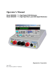
Operator's Manual
Model SM2060 7½ Digit Digital PCI Multimeter
Model SMX2060 7½ Digit Digital PXI Multimeter
Model SM2064 7½ Digit High Work Load PCI Digital Multimeter
Model SMX2064 7½ Digit High Work Load PXI Digital Multimeter
Signametrics Corporation
February 2005
Rev 1.1
CAUTION
In no event shall Signametrics or its Representatives are liable for any consequential damages whatsoever
(including, without limitation, damages for loss of business profits, business interruption, loss of business
information, or other loss) arising out of the use of or inability to use Signametrics products, even if Signametrics
has been advised of the possibility of such damages. Because some states do not allow the exclusion or limitation of
liability for consequential damages, the above limitations may not apply to you.
© 2004 Signametrics Corp. Printed in the USA. All rights reserved. Contents of this publication must not be
reproduced in any form without the permission of Signametrics Corporation.
Signametrics
2
TABLE OF CONTENTS
1.0 INTRODUCTION .................................................................................................................................................8
1.1 SAFETY CONSIDERATIONS..........................................................................................................................8
1.2 MINIMUM REQUIREMENTS .........................................................................................................................9
1.3 FEATURE SET .............................................................................................................................................9
2.0 SPECIFICATIONS .............................................................................................................................................10
2.1 DC VOLTAGE MEASUREMENT .................................................................................................................10
2.2 DC CURRENT MEASUREMENT .................................................................................................................10
2.3 RESISTANCE MEASUREMENTS ..................................................................................................................11
2.3.1 2-wire .....................................................................................................................................11
2.3.2 4-wire .....................................................................................................................................11
2.3.3 6-wire Guarded Resistance Measurement (SM2064) ............................................................11
2.3.4 Extended Resistance Measurements (SM2064) .....................................................................12
2.4 AC VOLTAGE MEASUREMENTS ...............................................................................................................12
2.4.1 AC Voltage True RMS Measurement .....................................................................................12
2.4.2 AC Peak-to-Peak Measurement (SM2064) ............................................................................14
2.4.3 AC Crest Factor Measurement (SM2064) .............................................................................15
2.4.4 AC Median Value Measurement (SM2064) ...........................................................................15
2.5 AC CURRENT MEASUREMENT, TRUE RMS .............................................................................................15
2.6 LEAKAGE MEASUREMENT (SM2064) ......................................................................................................16
2.7 RTD TEMPERATURE MEASUREMENT (SM2064) .....................................................................................16
2.8 THERMOCOUPLE TEMPERATURE MEASUREMENT (SM2064) ...................................................................17
2.9 ADDITIONAL COMPONENT MEASUREMENT CAPABILITY ..........................................................................17
2.9.1 Diode Characterization .........................................................................................................17
2.9.2 Capacitance, Ramp Method (SM2064)..................................................................................17
2.9.3 Capacitance, In-Circuit Method (SM2064) ..........................................................................19
2.9.4 Inductance Measurement (SM2064) ......................................................................................19
2.10 TIME MEASUREMENTS ...........................................................................................................................19
2.10.1 Threshold DAC ....................................................................................................................19
2.10.2 Frequency and Period Measurement...................................................................................20
2.10.3 Duty Cycle Measurement .....................................................................................................20
2.10.4 Pulse Width ..........................................................................................................................20
2.10.5 Totalizer ...............................................................................................................................21
2.11 TRIGGER FUNCTIONS .............................................................................................................................21
2.11.1 External Hardware Trigger (at DIN-7 connector) ..............................................................21
2.11.2 Analog Threshold Trigger....................................................................................................21
2.11.3 Delayed Hardware Trigger..................................................................................................21
2.12 MEASUREMENT APERTURE AND READ INTERVAL ..................................................................................21
2.13 SOURCE FUNCTIONS (SMX2064)...........................................................................................................23
2.13.1 DC Voltage Source ..............................................................................................................24
2.13.2 AC Voltage Source...............................................................................................................24
2.13.3 DC Current Source ..............................................................................................................24
2.14 ACCURACY NOTES .................................................................................................................................24
2.15 OTHER SPECIFICATIONS .........................................................................................................................25
3.0 GETTING STARTED.........................................................................................................................................27
3.1 SETTING THE DMM .................................................................................................................................27
3.2 INSTALLING THE DMM MODULE .............................................................................................................27
3.3 INSTALLING THE SOFTWARE ....................................................................................................................27
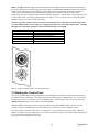
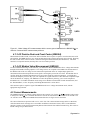
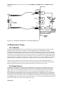
3.4 DMM INPUT CONNECTORS ......................................................................................................................28
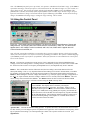
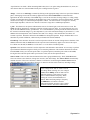
3.5 STARTING THE CONTROL PANEL ..............................................................................................................29
3.6 USING THE CONTROL PANEL ....................................................................................................................30
4.0 DMM OPERATION AND MEASUREMENT TUTORIAL...........................................................................32
3
Signametrics
4.1 VOLTAGE MEASUREMENT........................................................................................................................32
4.1.1 DC Voltage Measurements ....................................................................................................32
4.1.2 True RMS AC Voltage Measurements ...................................................................................32
4.1.3 AC Peak-to-Peak and Crest Factor (SM2064) ......................................................................33
4.1.4 AC Median Value Measurement (SM2064) ...........................................................................33
4.2 CURRENT MEASUREMENTS ......................................................................................................................33
4.2.1 Extended DC Current Measurements (SM2064) ...................................................................34
4.2.2 Improving DC Current Measurements ..................................................................................34
4.2.3 DC Current Measurements at a specific voltage ...................................................................34
4.3 RESISTANCE MEASUREMENTS ..................................................................................................................35
4.3.1 2-Wire Ohm Measurements ...................................................................................................35
4.3.2 4-Wire Ohm Measurements ...................................................................................................35
4.3.3 Using Offset Ohms function (SM2064) ..................................................................................36
4.3.4 6-wire Guarded Resistance Measurement (SM2064) ............................................................36
4.3.5 Extended Resistance Measurements (SM2064) .....................................................................37
4.3.6 Effects of Thermo-Voltaic Offset............................................................................................38
4.3.7 Guarding High Value Resistance Measurements (SM2064) .................................................39
4.4 LEAKAGE MEASUREMENTS (SM2064).....................................................................................................39
4.5 MEASUREMENT TIMING ...........................................................................................................................40
4.5.1 Aperture .................................................................................................................................40
4.5.2 Read Interval..........................................................................................................................40
4.6 RTD TEMPERATURE MEASUREMENT (SM2064) .....................................................................................42
4.7 INTERNAL TEMPERATURE (SM2064) .......................................................................................................42
4.8 DIODE CHARACTERIZATION .....................................................................................................................42
4.9 CAPACITANCE MEASUREMENT (SM2064) ...............................................................................................43
4.10 IN-CIRCUIT CAPACITANCE MEASUREMENT (SM2064) ..........................................................................43
4.11 INDUCTANCE MEASUREMENT (SM2064) ...............................................................................................44
4.12 CHARACTERISTIC IMPEDANCE MEASUREMENT (SM2064).....................................................................44
4.13 TRIGGER OPERATION .............................................................................................................................44
4.13.1 External Hardware Trigger .................................................................................................44
4.13.2 Analog Threshold Trigger....................................................................................................45
4.13.3 Software Generated Triggered Operations..........................................................................45
4.14 FREQUENCY AND TIME MEASUREMENTS ...............................................................................................47
4.14.1 Threshold DAC ....................................................................................................................47
4.14.2 Frequency and Period Measurements .................................................................................48
4.14.3 Duty Cycle Measurement .....................................................................................................48
4.14.4 Pulse Width ..........................................................................................................................48
4.14.5 Totalizer Event Counter .......................................................................................................48
4.15 SOURCING FUNCTIONS (SM2064)..........................................................................................................49
4.15.1 DC Voltage Source ..............................................................................................................49
4.15.2 AC Voltage Source...............................................................................................................50
4.15.3 DC Current Source ..............................................................................................................51
4.15.4 Source Current - Measure Voltage ......................................................................................51
4.16 INTERFACING TO THE SM4040 SERIES RELAY SCANNERS ......................................................................51
4.16.1 Triggering the SM2060 DMM’s...........................................................................................51
4.16.2 Multiplexing with the SM2060 DMM’s................................................................................52
4.16.3 Interface Commands and Timing.........................................................................................52
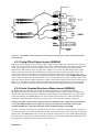
4.17 MEASURING TEMPERATURE WITH THERMOCOUPLES .............................................................................53
4.18 USING THE PXI BUS TRIGGER FACILITIES (SMX2064) ..........................................................................53
4.18.1 Selecting PXI Trigger Outputs.............................................................................................53
4.18.2 Selecting PXI Trigger Inputs ...............................................................................................54
5.0 WINDOWS INTERFACE ..................................................................................................................................55
5.1 DISTRIBUTION FILES ................................................................................................................................55
5.2 USING THE SM2060 DRIVER WITH C++ OR SIMILAR SOFTWARE ............................................................57
5.2.1 Multiple Card Operations under Windows............................................................................57
5.3 VISUAL BASIC FRONT PANEL APPLICATION .............................................................................................58
5.3.1 Visual Basic Simple Application ............................................................................................59
5.4 WINDOWS DLL DEFAULT MODES AND PARAMETERS .............................................................................60
Signametrics
4
5.5 USING THE SM2060 DLL WITH LABWINDOWS/CVI®............................................................................60
5.6 WINDOWS COMMAND LANGUAGE ...........................................................................................................60
DMMArmAnalogTrigger ................................................................................................................60
DMMArmTrigger............................................................................................................................62
DMMBurstBuffRead .......................................................................................................................63
DMMBurstRead ..............................................................................................................................64
DMMCalibrate................................................................................................................................65
DMMCleanRelay ............................................................................................................................66
DMMClearBuffer............................................................................................................................67
DMMClearMinMax ........................................................................................................................67
DMMClosePCI ...............................................................................................................................68
DMMDelay .....................................................................................................................................68
DMMDelayedTrigger .....................................................................................................................69
DMMDisableTrimDAC...................................................................................................................70
DMMDisArmTrigger ......................................................................................................................70
DMMDutyCycleStr .........................................................................................................................71
DMMErrString................................................................................................................................71
DMMFrequencyStr .........................................................................................................................72
DMMGetACCapsR .........................................................................................................................73
DMMGetAperture ...........................................................................................................................73
DMMGetBufferSize.........................................................................................................................74
DMMGetBusInfo.............................................................................................................................74
DMMGetCalDate............................................................................................................................75
DMMGetdB.....................................................................................................................................76
DMMGetdBStr ................................................................................................................................76
DMMGetCJTemp............................................................................................................................77
DMMGetDeviation .........................................................................................................................77
DMMGetDeviatStr..........................................................................................................................78
DMMGetFuncRange.......................................................................................................................78
DMMGetFunction...........................................................................................................................79
DMMGetGrdVer .............................................................................................................................79
DMMGetHwVer..............................................................................................................................80
DMMGetID .....................................................................................................................................80
DMMGetManDate ..........................................................................................................................81
DMMGetMax ..................................................................................................................................82
DMMGetMaxStr .............................................................................................................................82
DMMGetMin...................................................................................................................................83
DMMGetMinStr ..............................................................................................................................83
DMMGetRange ...............................................................................................................................84
DMMGetReadInterval ....................................................................................................................85
DMMGetSourceFreq ......................................................................................................................85
DMMGetTCType.............................................................................................................................86
DMMGetTriggerInfo.......................................................................................................................86
DMMGetType .................................................................................................................................87
DMMGetVer ...................................................................................................................................87
DMMInit .........................................................................................................................................88
DMMIsAutoRange ..........................................................................................................................88
DMMIsInitialized............................................................................................................................89
DMMIsRelative ...............................................................................................................................89
DMMOpenPCI................................................................................................................................90
DMMOpenCalACCaps ...................................................................................................................90
DMMOpenTerminalCal..................................................................................................................91
DMMPeriodStr ...............................................................................................................................92
DMMPolledRead ............................................................................................................................92
DMMPolledReadCmd.....................................................................................................................93
DMMPolledReadStr........................................................................................................................94
DMMQuickInit................................................................................................................................94
DMMRead.......................................................................................................................................95
DMMReadBuffer.............................................................................................................................96
DMMReadBufferStr ........................................................................................................................97
5
Signametrics
DMMReadCJTemp .........................................................................................................................97
DMMReadCrestFactor ...................................................................................................................98
DMMReadDutyCycle ......................................................................................................................99
DMMReadFrequency......................................................................................................................99
DMMReadInductorQ ....................................................................................................................100
DMMReadMeasurement ...............................................................................................................101
DMMReadMedian.........................................................................................................................101
DMMReadNorm............................................................................................................................102
DMMReadPeakToPeak.................................................................................................................102
DMMReadPeriod..........................................................................................................................103
DMMReadStr ................................................................................................................................104
DMMReadTotalizer ......................................................................................................................105
DMMReadWidth ...........................................................................................................................105
DMMReady ...................................................................................................................................106
DMMSetACCapsDelay .................................................................................................................106
DMMSetACCapsLevel ..................................................................................................................107
DMMSetACVSource .....................................................................................................................107
DMMSetAperture..........................................................................................................................108
DMMSetAutoRange ......................................................................................................................109
DMMSetBuffTrigRead ..................................................................................................................109
DMMSetCapsAveSamp .................................................................................................................110
DMMSetCJTemp...........................................................................................................................111
DMMSetCompThreshold ..............................................................................................................112
DMMSetCounterRng.....................................................................................................................112
DMMSetDCISource ......................................................................................................................113
DMMSetDCVSource .....................................................................................................................114
DMMSetFastRMS .........................................................................................................................115
DMMSetFuncRange......................................................................................................................115
DMMSetFunction..........................................................................................................................116
DMMSetInductFreq ......................................................................................................................116
DMMSetOffsetOhms .....................................................................................................................117
DMMSetPXITrigger......................................................................................................................117
DMMSetRange..............................................................................................................................118
DMMSetReadInterval ...................................................................................................................119
DMMSetReference ........................................................................................................................119
DMMSetRelative ...........................................................................................................................120
DMMSetRTD ................................................................................................................................121
DMMSetSensorParams.................................................................................................................122
DMMSetSourceMode....................................................................................................................122
DMMSetSync ................................................................................................................................123
DMMSetTCType ...........................................................................................................................124
DMMSetTempUnits.......................................................................................................................124
DMMSetTrigPolarity ....................................................................................................................125
DMMSetTrigRead .........................................................................................................................125
DMMSetTrimDAC ........................................................................................................................126
DMMStartTotalizer.......................................................................................................................127
DMMStopTotalizer .......................................................................................................................128
DMMTerminate.............................................................................................................................128
DMMTrigger.................................................................................................................................129
DMMTriggerBurst ........................................................................................................................130
DMMWidthStr...............................................................................................................................131
5.7 CALIBRATION SERVICE COMMANDS ......................................................................................................133
AC_zero ........................................................................................................................................133
DMMLoadCalFile.........................................................................................................................133
GetGain.........................................................................................................................................134
GetOffset .......................................................................................................................................134
SetFcomp ......................................................................................................................................135
SetOffset ........................................................................................................................................136
Linearize_AD ................................................................................................................................136
Read_ADcounts ............................................................................................................................137
Signametrics
6
5.8 MAINTANANCE COMMANDS ..................................................................................................................138
GrdXingTest..................................................................................................................................138
5.7 ERROR CODES ........................................................................................................................................138
5.8 WARNING CODES ...................................................................................................................................139
6.0 MAINTENANCE ..............................................................................................................................................139
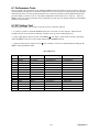
6.1 PERFORMANCE TESTS ............................................................................................................................141
6.2 DC VOLTAGE TEST ................................................................................................................................141
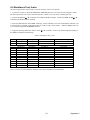
6.3 RESISTANCE TEST, 2-WIRE .....................................................................................................................142
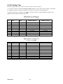
6.4 RESISTANCE TEST, 4-WIRE .....................................................................................................................143
6.5 AC VOLTAGE TEST ................................................................................................................................144
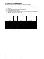
6.6 DC CURRENT TEST ................................................................................................................................145
6.7 AC CURRENT TEST ................................................................................................................................146
NOTE: SOME RANGES APPLY TO 2064 ONLY. PLEASE REFER TO CHAPTER 2.0 (SPECIFICATION). .................146
6.8 CAPACITANCE TEST (SM2064 ONLY) ....................................................................................................147
6.8 INDUCTANCE TEST (SM2064 ONLY) ......................................................................................................148
6.9 FREQUENCY COUNTER TEST ( SM2064 ONLY) ......................................................................................149
6.10 CALIBRATION .......................................................................................................................................150
7.0 WARRANTY AND SERVICE.........................................................................................................................152
8.0 ACCESSORIES.................................................................................................................................................152
7
Signametrics
1.0 Introduction
Congratulations! You have purchased a Personal Computer (PC) Plug-in instrument with analog and systems
performance that rivals the best, all-in-one box, instruments. The SM2060 and SMX2064 Digital Multimeters
(DMM’s) are easy to setup and use, have sophisticated analog and digital circuitry to provide very repeatable
measurements, and are protected to handle any unexpected situations your measurement environment may
encounter. To get years of reliable service from these DMM’s, please take a few moments and review this manual
before installing and using this precision instrument.
This manual describes the SM2060 and SM2064 DMM’s. The SMX2060 is identical to the SM2060 and the
SMX2064 is identical to the SM2064. The only difference is the bus type. The SM206X is a PCI module, while the
SMX206X is a PXI/cPCI module.
Note: In this manual, all references made to the "SM2060" are applicable to the SMX2060, and references to the
“SM2064” are applicable to the SMX2064. References to “DMM” apply to the SM2060, SMX2060, SM2064 and
SMX2064. Features unique to the SM2064 will be identified as such.
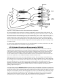
1.1 Safety Considerations
Safety Considerations
The SM2060 series of DMM’s is capable of measuring up to 300 VDC or 250 VAC across the Volt HI
and LO terminals, and can also measure common mode signals that "float" the DMM above EARTH
ground by up to 300 VDC or 250 VAC. When making common mode measurements, the majority of the
circuits inside the DMM are at the common mode voltage. These voltages can be lethal and can KILL!
During and after installing your DMM, check to see that there are no wires or ribbon cables from
your PC trapped inside the DMM.
The DMM comes installed with four shields (bottom, top and two edge strips) that must not be removed
for performance as well as safety reasons. Removal of these shields and/or improper assembly of the
shields can result in lethal voltages occurring within your PC. Be sure to check your installation before
closing the cover on your personal computer.
Warning
Check to see that no loose wires or ribbon cables infringe upon any of the internal circuits of the
DMM, as this may apply measurement voltages to your computer, causing electrocution and/or
damage to your computer!
To avoid shock hazard, install the DMM only into a computer that has its power connector
connected to a power receptacle with an earth safety ground.
When making any measurements above 50 VDC or 40 VAC, only use Safety Test Leads. Examples
of these are the Signametrics Basic Test Leads and Deluxe Test Leads, offered as an accessory with the
Signametrics DMM’s.
Signametrics
8
1.2 Minimum Requirements
The SM2060 series of system DMM’s are precision plug-in modules that are compatible with IBM type personal
computers (PCs), PXI and cPCI chassis. It requires as a minimum a Pentiums computer. They require a half-length
expansion slot on the PCI bus or 3U PXI slot. A mouse must be installed when controlling the DMM from the
Windows Control Panel. The SM2060 comes with a Windows' DLL, for operation with Windows' Version
95/98/Me/2000/XP and NT4.0.
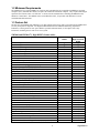
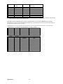
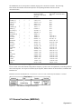
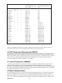
1.3 Feature Set
The base unit, the SM2060, has traditional 7-1/2 digit features and it can be used as a general purpose DMM, where
accuracy and speed are important. The High Workload Multi Function SM2064 adds timing, capacitance,
inductance, sourcing and a lot more speed. With its specialized measurements, it can replace some costly
instruments, shrinking the size and cost of a test system.
SM2060 and SM2064 7½ Digit DMM’s feature table:
Function
SM/SMX2060
DMM
DCV five ranges 240mV to 330V
ACV five ranges 240mV to 330V
2-Wire Ohms, six ranges 240 Ω to 24 MΩ
4-Wire Ohms, six ranges 240 Ω to 24 MΩ
DC current, four ranges 2.4 mA to 2.4 A
AC current, four ranges 2.4 mA to 2.4 A
Diode V/I characteristics at 100 ηA to 1mA
Auto range, Relative
Min/Max, dB and percent deviation functions
On board measurement buffer
External and threshold trigger
Thermocouples type; B, E, J, K, N, R, S, T
High Dynamic range; +24,000,000 counts
Frequency / Period measurement
Measurement rate: 0.2 to 1,400/sec
Measurement rate: to 20,000/sec
Capacitance, ramp type, eight ranges, 1 nF to 10 mF
Capacitance, In-Circuit method five ranges, 24nF to 2.4mF
Inductance, six ranges 33 µH to 3.3 H
Internal DMM temperature sensor
Offset Ohms
Temperature types pt385, 3911, 3916, 3926, Copper, variable Ro
Pulse width, pos./neg., & duty cycle
Totalizer/event counter
Variable threshold DAC; all timing measure.
Peak to Peak, Crest factor, Median
Six wire Ohms (with force/sense)
DCV source to ±10.0 V
ACV source 0 to 20 V pk-pk, 2 Hz to 75 KHz
DC current source, 1 nA to 12.5 mA
Leakage measurement to ±10.0V three ranges 240nA, 2.4uA, 25uA
Expanded ranges
2-Wire Ohms two additional ranges 24 Ω and 240 MΩ
4-Wire Ohms additional range 24 Ω
Resistance with V&I limits (to 10GΩ)
DC Current four additional ranges 240nA, 2.4µA, 24µA, 240µA
9
√
√
√
√
√
√
√
√
√
√
√
√
√
√
√
SM/SMX2064
High Workload
DMM
√
√
√
√
√
√
√ (plus 10mA)
√
√
√
√
√
√
√
√
√
√
√
√
√
√
√
√
√
√
√
√
√
√
√
√
√
√
√
√
√
Signametrics
2.0 Specifications
The following specifications are based on both, verification of large number of units as well as
mathematical evaluation. They should be considered under the environment specified.
It is important to note that a DMM specified range is expressed as a numeric value indicating the highest
absolute voltage that can be measured. The lowest value that can be detected is expressed by the
corresponding resolution for the range.
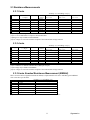
2.1 DC Voltage Measurement
Input Characteristics
• Input Resistance 240 mV, 2.4 V Ranges: >10 GΩ, with typical leakage of 50pA
• Input Resistance 24 V, 240 V, 330V Ranges: 10.00 MΩ
Accuracy ± (% of reading + Volts) [1]
Range
240 mV
2.4 V
24 V
240 V
330 V
Full Scale
7-½ Digits
240.00000 mV
2.4000000 V
24.000000 V
240.00000 V
330.00000 V
Resolution
10 ηV
100 ηV
1 µV
10 µV
10 µV
24 hours
23°C ± 1°C
0.003 + 1 µV
0.002 + 3 µV
0.003 + 150 µV
0.004 + 200 µV
0.005 + 250 µV
90 Days
23°C ± 5°C
0.004 + 1.5 µV
0.0025 + 5 µV
0.004 + 250 µV
0.005 + 300 µV
0.01+ 400 µV
One Year 23°C
± 5°C
0.005 + 2 µV
0.003 + 10 µV
0.005 + 300 µV
0.006 + 0.5 mV
0.015 + 0.7 mV
[1] With Aperture set to ≥ 0.5 Sec, and within one hour from Self Calibration (S-Cal).
For resolution at smaller Apertures, see the following table. Use this table for DC Volts, DC current
and Resistance measurements.
Measurement Aperture
Maximum reading
rate
SM2060, SM2064
Resolution
0.5 s < Aperture
2 / second
7-1/2 digits
25 bits
10 ms < Aperture
100 / second
6-1/2 digits
22 bits
1200 / second
5-1/2 digits
18 bits
625µs < Aperture
2.5us < Aperture [2]
20,000 / second [2]
4-1/2 digits
14 bits
[2] Available only with the SM2064.
DCV Noise Rejection Normal Mode Rejection, at 50, 60, or 400 Hz ± 0.5%, is better than 95 dB
for apertures of 0.160s and higher. Common Mode Rejection (with 1 kΩ lead imbalance) is better
than 120 dB for these conditions.
2.2 DC Current Measurement
Input Characteristics
•
•
Number of shunts Five in SM2064, two in the SM2060
Protected with 2.5A Fast blow fuse
Accuracy ± (% of reading + Amps) [1]
Range
240 ηA [2]
2.4 µA [2]
24 µA [2]
240 µA [2]
2.4 mA
24 mA
240 mA
2.4 A
Full Scale
6-½ Digits
240.0000 ηA
2.400000 µA
24.00000 µA
240.000 µA
2.40000 mA
24.0000 mA
240.000 mA
2.40000 A
Resolution
0.1 pA
1 pA
10 pA
10 ηA
10 ηA
100 ηA
1 µA
10 µA
Max Burden
Voltage
100 µV
100 µV
100 µV
2.5mV
25mV
250mV
55mV
520mV
24 hours
23°C ± 5°C
0.07 + 40pA
0.05 + 70pA
0.05 + 400pA
0.052 + 200 ηA
0.05 + 300 ηA
0.05 + 350 ηA
0.05 + 50 µA
0.3 + 60 µA
90 Days
23°C ± 5°C
0.1 + 45pA
0.08 + 90pA
0.08 + 600pA
0.07 + 300 ηA
0.06 + 400 ηA
0.065 + 450 ηA
0.055 + 60 µA
0.4 + 70 µA
[1] With Aperture set to ≥ 0.96 Sec, and within one hour from Zero (Relative control).
[2] Available only with the SM2064.
Signametrics
10
One Year 23°C
± 5°C
0.17 + 60pA
0.21 + 150pA
0.13 + 0.8nA
0.1 + 400 ηA
0.07 + 550 ηA
0.08 + 550 ηA
0.065 + 80 µA
0.45 + 90 µA
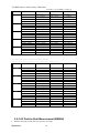
2.3 Resistance Measurements
2.3.1 2-wire
Accuracy ± (% of reading + Ω) [1]
Range [4]
24 Ω[3]
240 Ω
2.4 kΩ
24 kΩ
240 kΩ
2.4 MΩ
24 MΩ
240 MΩ[3]
Full Scale
7 ½ Digits
24.000000 Ω
240.00000 Ω
2.4000000 kΩ
24.000000 kΩ
240.00000 kΩ
2.4000000 MΩ
24.0000 MΩ
240.000 MΩ
Resolution
1 µΩ
10 µΩ
100 µΩ
1 mΩ
10 mΩ
100 mΩ
100 Ω
1 kΩ
Source
current
10 mA
1 mA
1 mA
100 µA
10 µA
1 µA
100 nA
10 nA
24 hours
23°C ± 1°C
0.0038 + 1.4 mΩ [2]
0.0037 + 4.5 mΩ [2]
0.0023 + 28 mΩ
0.0025 + 300 mΩ
0.0055 + 3.2 Ω
0.018 + 40 Ω
0.12 + 400 Ω
0.8 + 20 kΩ
90 Days
23°C ± 5°C
0.005 + 1.6 mΩ [2]
0.0046 + 5 mΩ [2]
0.004 + 32 mΩ
0.004 + 330 mΩ
0.006 + 4 Ω
0.03 + 50 Ω
0.13 + 500 Ω
1.0 + 30 kΩ
One Year
23°C ± 5°C
0.008 + 2 mΩ [2]
0.007 + 6 mΩ [2]
0.006 + 33 mΩ
0.006 + 350 mΩ
0.007 + 5 Ω
0.04 + 70 Ω
0.2 + 600 Ω
1.3 + 50 kΩ
[1] With Aperture set to ≥ 0.5 Sec, and within one hour from Self Calibration (S-Cal).
[2] Use of S-Cal and Relative to improve measurement floor.
[3] Ranges are only available with the SM2064.
[4] Test voltages are 2.4V max with the exception of the 24 Ω and 240 Ω ranges 240 mV.
2.3.2 4-wire
Accuracy ± (% of reading + Ω) [1]
Range [4]
24 Ω [3]
240 Ω
2.4 kΩ
24 kΩ
240 kΩ
2.4 MΩ
24 MΩ
Full Scale
7 ½ Digits
24.000000 Ω
240.00000 Ω
2.4000000 kΩ
24.000000 kΩ
240.00000 kΩ
2.4000000 MΩ
24.0000 MΩ
Resolution
1 µΩ
10 µΩ
100 µΩ
1 mΩ
10 mΩ
100 mΩ
100 Ω
Source
current
10 mA
1 mA
1 mA
100 µA
10 µA
1 µA
100 nA
24 hours
23°C ± 1°C
0.0038 + 0.7 mΩ [2]
0.0037 + 3 mΩ [2]
0.0023 + 28 mΩ
0.0025 + 300 mΩ
0.0055 + 3.2 Ω
0.018 + 40 Ω
0.12 + 400 Ω
90 Days
23°C ± 5°C
0.005 + 0.8 mΩ [2]
0.0046 + 4 mΩ [2]
0.004 + 32 mΩ
0.004 + 330 mΩ
0.007 + 4 Ω
0.03 + 50 Ω
0.13 + 500 Ω
One Year
23°C ± 5°C
0.008 + 1 mΩ [2]
0.007 + 5 mΩ [2]
0.006 + 33 mΩ
0.006 + 350 mΩ
0.007 + 5 Ω
0.04 + 70 Ω
0.2 + 600 Ω
[1] With Aperture set to ≥ 0.5 Sec, and within one hour from Self Calibration (S-Cal).
[2] Use of Relative to facilitate indicated floor (adder part of spec).
[3] 24 Ω range only available with SM2064.
[4] Test voltages are 2.4V max with the exception of the 24 Ω and 240 Ω ranges 240 mV.
2.3.3 6-wire Guarded Resistance Measurement (SM2064)
This is an in-circuit forced guard measurement method, as implemented in ICT testers. Add this typical additional
error to the above specification.
Accuracy ± (% of reading + Ω)
Range
24 Ω [3]
240 Ω
2.4 kΩ
24 kΩ
240 kΩ
24 MΩ
Guard forced current
10 mA
1 mA
1 mA
100 µA
10 µA
1 µA
One Year 23°C ± 5°C [1]
0.3 + 4 mΩ
0.003 + 20 mΩ
0.005 + 100 mΩ
0.03 + 1 Ω
0.35 + 10 Ω
0.85 + 1000 Ω
[1] This table should be used in conjunction with the 2-wire and 4-wire table above.
11
Signametrics
2.3.4 Extended Resistance Measurements (SM2064)
Characteristics
• Test Voltage Adjustable between -10V and +10V in 5mV steps
Accuracy ± (% of reading + Amps) [1]
Range
Resol
Current
Limit
[3]
90 Days
One Year 23°C
Measurement range
23°C ± 5°C
ution
± 5°C
25µA
0.2 + 50Ω
400kΩ
1kΩ to 100MΩ
10Ω
0.33 + 90Ω
0.3 + 350Ω
4MΩ
10kΩ to 1GΩ
100Ω 2.5µA
0.43 + 550Ω
250nA
0.4 + 3kΩ
40MΩ
100kΩ to 10GΩ
1kΩ
0.55 + 4.5kΩ
[1] With Aperture set to ≥ 0.5 Sec, and within one hour from Zero (Relative control).
[2] Multiply “% of reading” by 1/Voltage Source for applied voltages below 1V
[3] Limit is reached when the test current exceeds the Current Limit, or it is below 0.04% of
this value.
2.4 AC Voltage Measurements
Input Characteristics
•
•
•
•
•
Input Resistance 1 MΩ, shunted by < 300 pF, all ranges
Max. Crest Factor 4 at Full Scale, increasing to 7 at Lowest Specified Voltage
AC coupled Specified range: 10 Hz to 100 kHz
Typical Settling time < 0.5 sec to within 0.1% of final value
Typical Settling time Fast RMS < 0.05 sec to within 0.1% of final value
2.4.1 AC Voltage True RMS Measurement
Range
240 mV
2.4 V
24 V
240 V
330 V
Full Scale 7-½ Digits
240.0000 mV
2.400000 V
24.00000 V
240.0000 V
330.0000 V
Lowest specified Voltage
5 mV [1]
10 mV
100 mV
1V
2V
Resolution
100 ηV
1 µV
10 µV
100 µV
100 µV
[1] Between 5 mV and 10 mV, add 100 µV additional errors to the accuracy table below.
[2] Signal is limited to 8x10⁶ Volt Hz Product. For example, the largest frequency input at 250 V is
32 kHz, or 8x10⁶ Volt x Hz.
Signametrics
12
AC Volts Accuracy with Fast RMS disabled (default).
With Fast RMS disabled, settling time to rated accuracy is within 0.5
Accuracy ± (% of reading + Volts) [1]
Range
240 mV
2.4 V
24 V
240 V
330 V
Frequency
10 Hz - 20 Hz
20 Hz - 47 Hz
47 Hz - 10 kHz
10 kHz - 50 kHz
50 kHz - 100 kHz
10 Hz - 20 Hz
20 Hz - 47 Hz
47 Hz - 10 kHz
10 kHz - 50 kHz
50 kHz - 100 kHz
10 Hz - 20 Hz
20 Hz - 47 Hz
47 Hz - 10 kHz
10 kHz - 50 kHz
50 kHz - 100 kHz
10 Hz - 20 Hz
20 Hz - 47 Hz
47 Hz - 10 kHz
10 kHz - 50 kHz
50 kHz - 100 kHz
10 Hz - 20 Hz
20 Hz - 47 Hz
47 Hz - 10 kHz
10 kHz - 50 kHz
50 kHz - 100 kHz
24 hours
23°C ± 1°C
3.0 + 350 µV
0.92 + 150 µV
0.13 + 100 µV
0.55 + 160 µV
5.3 + 350 µV
3.0 + 2 mV
0.93 + 1.3 mV
0.05 + 1 mV
0.62 + 1.2 mV
5.1 + 1.5 mV
3.0 + 14 mV
0.93 + 12 mV
0.06 + 10 mV
0.31 + 18 mV
2.0 + 30 mV
3.0 + 140 mV
0.93 + 120 mV
0.04 + 100 mV
0.32 + 150 mV
2.5 + 200 mV
3.0 + 200 mV
1.0 + 180 mV
0.05 + 150 mV
0.34 + 200 mV
2.5 + 270 mV
90 Days
23°C ± 5°C
3.1 + 380 µV
0.93 + 170 µV
0.14 + 110 µV
0.6 + 200 µV
5.4 + 370 µV
3.1 + 2.2 mV
0.96 + 1.5 mV
0.055 + 1.1 mV
0.65 + 1.3 mV
5.2 + 1.7 mV
3.1 + 16 mV
0.96 + 14 mV
0.065 + 11 mV
0.33 + 21 mV
2.2 + 35 mV
3.1 + 160 mV
0.96 + 130 mV
0.045 + 110 mV
0.4 + 170 mV
2.8 + 240 mV
3.1 + 160 mV
1.1 + 200 mV
0.07 + 200 mV
0.45 + 250 mV
2.8 + 350 mV
s.
One Year
23°C ± 5°C
3.2 + 430 µV
0.95 + 200 µV
0.15 + 120 µV
0.63 + 230 µV
5.6 + 400 µV
3.2 + 2.5 mV
1.0 + 1.7 mV
0.065 + 1.2 mV
0.70 + 1.5 mV
5.3 + 2 mV
3.3 + 20 mV
1.0 + 16 mV
0.073 + 13 mV
0.35 + 25 mV
2.4 + 40 mV
3.3 + 200 mV
1.0 + 150 mV
0.06 + 130 mV
0.45 + 200 mV
3.2 + 300 mV
3.3 + 200 mV
1.1 + 250 mV
0.08 + 230 mV
0.5 + 300 mV
3.2 + 400 mV
ACV Noise Rejection Common Mode rejection, for 50 Hz or 60 Hz with 1 kΩ imbalance in either lead, is better
than 60 dB.
AC Volts Accuracy with Fast RMS enabled.
13
Signametrics
Fast RMS settles to rated accuracy within 50ms.
Accuracy ± (% of reading + Volts) [1]
Range
240 mV
2.4 V
24 V
240 V
330 V
Frequency
350 Hz - 800 Hz
800 Hz - 10 kHz
10 kHz - 50 kHz
50 kHz - 100 kHz
350 Hz - 800 Hz
800 Hz - 10 kHz
10 kHz - 50 kHz
50 kHz - 100 kHz
350 Hz - 800 Hz
800 Hz - 10 kHz
10 kHz - 50 kHz
50 kHz - 100 kHz
350 Hz - 800 Hz
800 Hz - 10 kHz
10 kHz - 50 kHz
50 kHz - 100 kHz
350 Hz - 800 Hz
800 Hz - 10 kHz
10 kHz - 50 kHz
50 kHz - 100 kHz
24 hours
23°C ± 1°C
0.6 + 150 µV
0.13 + 100 µV
0.55 + 160 µV
5.3 + 350 µV
0.93 + 1.3 mV
0.068 + 1 mV
0.62 + 1.2 mV
5.1 + 1.5 mV
0.93 + 12 mV
0.065 + 10 mV
0.31 + 18 mV
2.0 + 30 mV
0.93 + 120 mV
0.062 + 100 mV
0.32 + 150 mV
2.5 + 200 mV
1.0 + 180 mV
0.065 + 150 mV
0.34 + 200 mV
2.5 + 270 mV
90 Days
23°C ± 5°C
0.65 + 170 µV
0.14 + 110 µV
0.6 + 200 µV
5.4 + 370 µV
0.96 + 1.5 mV
0.075 + 1.1 mV
0.65 + 1.3 mV
5.2 + 1.7 mV
0.96 + 14 mV
0.068 + 11 mV
0.33 + 21 mV
2.2 + 35 mV
0.96 + 130 mV
0.065 + 110 mV
0.4 + 170 mV
2.8 + 240 mV
1.1 + 200 mV
0.07 + 200 mV
0.45 + 250 mV
2.8 + 350 mV
One Year
23°C ± 5°C
0.7 + 200 µV
0.15 + 120 µV
0.63 + 230 µV
5.6 + 400 µV
1.0 + 1.7 mV
0.08 + 1.2 mV
0.70 + 1.5 mV
5.3 + 2 mV
1.0 + 16 mV
0.073 + 13 mV
0.35 + 25 mV
2.4 + 40 mV
1.0 + 150 mV
0.08 + 130 mV
0.45 + 200 mV
3.2 + 300 mV
1.1 + 250 mV
0.08 + 230 mV
0.5 + 300 mV
3.2 + 400 mV
AC Volts Accuracy with Slow RMS (default).
Settles to rated accuracy within 1X to 10X signal period, settable by user.
Range
240 mV
2.4 V
24 V
240 V
330 V
Frequency
0.5 Hz - 10 Hz
10 Hz - 20 Hz
20 Hz - 60 Hz
60 kHz - 200 Hz
0.5 Hz - 10 Hz
10 Hz - 20 Hz
20 Hz - 60 Hz
60 kHz - 200 Hz
0.5 Hz - 10 Hz
10 Hz - 20 Hz
20 Hz - 60 Hz
60 kHz - 200 Hz
0.5 Hz - 10 Hz
10 Hz - 20 Hz
20 Hz - 60 Hz
60 kHz - 200 Hz
0.5 Hz - 10 Hz
10 Hz - 20 Hz
20 Hz - 60 Hz
60 kHz - 200 Hz
24 hours
23°C ± 1°C
0.25 + 100 µV
0.3 + 150 µV
0.13 + 100 µV
0.55 + 160 µV
0.2 + 2 mV
0.3 + 1.3 mV
0.5 + 1 mV
0.62 + 1.2 mV
3.0 + 14 mV
0.93 + 12 mV
0.06 + 10 mV
0.31 + 18 mV
3.0 + 140 mV
0.93 + 120 mV
0.04 + 100 mV
0.32 + 150 mV
3.0 + 200 mV
1.0 + 180 mV
0.05 + 150 mV
0.34 + 200 mV
90 Days
23°C ± 5°C
0.3 + 200 µV
0.35 + 170 µV
0.14 + 110 µV
0.6 + 200 µV
0.25 + 2.2 mV
0.35 + 1.5 mV
0.55 + 1.1 mV
0.65 + 1.3 mV
3.1 + 16 mV
0.96 + 14 mV
0.065 + 11 mV
0.33 + 21 mV
3.1 + 160 mV
0.96 + 130 mV
0.045 + 110 mV
0.4 + 170 mV
3.1 + 160 mV
1.1 + 200 mV
0.07 + 200 mV
0.45 + 250 mV
One Year
23°C ± 5°C
0.35 + 300 µV
0.4 + 200 µV
0.15 + 120 µV
0.63 + 230 µV
0.3 + 2.5 mV
1.0 + 1.7 mV
0.65 + 1.2 mV
0.70 + 1.5 mV
3.3 + 20 mV
1.0 + 16 mV
0.073 + 13 mV
0.35 + 25 mV
3.3 + 200 mV
1.0 + 150 mV
0.06 + 130 mV
0.45 + 200 mV
3.3 + 200 mV
1.1 + 250 mV
0.08 + 230 mV
0.5 + 300 mV
2.4.2 AC Peak-to-Peak Measurement (SM2064)
•
Measures the peak-to-peak value of a repetitive waveform.
Signametrics
14
ACV
Range
240 mV
2.4 V
24 V
240 V
Lowest specified
input voltage
(Vp-p)
0.1 V
1.0 V
10 V
100 V
Full Scale
reading (Vp-p)
Resolution
Typical Accuracy 23°C ± 5°C
One Year [1]
1.9 V
16 V
190 V
850 V
1 mV
10 mV
100 mV
1V
0.5 ± 3 mV
0.5 ± 40 mV
0.5 ± 700 mV
0.55 ± 6 V
[1] Signal frequency range 30 Hz to 60 kHz.
2.4.3 AC Crest Factor Measurement (SM2064)
•
Measures the crest factor (CF) of a repetitive waveform
ACV
Range
240 mV
2.4 V
24 V
240 V
330 V
Lowest specified
input voltage
(Vp-p)
0.1 V
1.0 V
10 V
100 V
100 V
Highest specified input
voltages (Vp-p)
Resolution
Typical Accuracy 23°C ± 5°C
One Year [1]
1.9 V
16 V
190 V
700 V
850 V
0.01
0.01
0.01
0.01
0.01
2.2 ±0.3
2.1 ±0.1
2.0 ±0.1
2.0 ±0.1
2.0 ±0.1
[1] Crest factor measurement requires signal frequency of 30 Hz to 60 kHz.
2.4.4 AC Median Value Measurement (SM2064)
•
•
Measures the mid-point between the positive and negative peaks of a repetitive waveform
Used to determine the Threshold DAC setting for optimal frequency and timing measurements
ACV
Range
240 mV
2.4 V
24 V
240 V
330 V
Lowest specified input
voltage (Vp-p)
0.08 V
0.80 V
8V
80 V
80 V
Full Scale
reading
±0.95 V
±9.5 V
±95.0 V
±350.0 V
±350.0 V
Resolution
Typical Accuracy 23°C ± 5°C One Year [1]
1 mV
10 mV
100 mV
1V
1V
2.0% ±17 mV
3% ±160 mV
3% ±1.4 V
3% ±12 V
3% ±12 V
[1] Median measurements require a repetitive signal with frequency range of 30 Hz to 30 KHz.
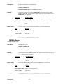
2.5 AC Current Measurement, True RMS
15
Signametrics
Input Characteristics
• Crest Factor 4 at Full Scale, increasing to 10 at Lowest Specified Current
• Protected with 2.5 A Fast Blow fuse
Range
Full Scale 6 1/2 Digits
2.4 mA
24 mA
240 mA
2.4 A
2.400000 mA
24.00000 mA
240.0000 mA
2.400000 A
Lowest Specified
Current
60 µA
300 µA
3 mA
30 mA
Maximum Burden
Voltage (RMS)
25mV
250mV
55mV
520mV
Resolution
1 nA
10 nA
100 nA
1 uA
Accuracy ± (% of reading + Amps)
Range
2.4 mA
24 mA
240 mA
2.4 A
Frequency [1]
10 Hz - 20 Hz
20 Hz - 47 Hz
47 Hz - 1 kHz
1 kHz - 10 kHz
10 Hz - 20 Hz
20 Hz - 47 Hz
47 Hz - 1 kHz
1 kHz - 10 kHz
10 Hz - 20 Hz
20 Hz - 47 Hz
47 Hz - 1 kHz
1 kHz - 10 kHz
10 Hz - 20 Hz
20 Hz - 47 Hz
47 Hz - 1 kHz
1 kHz - 10 kHz
24 hours
23°C ± 1°C
3.8 + 4 µA
0.9 + 4 µA
0.04 + 1.5 µA
0.12 + 4 µA
1.8 + 30 µA
0.6 + 30 µA
0.07 + 10 µA
0.21 + 30 µA
1.8 + 400 µA
0.6 + 400 µA
0.1 + 100 µA
0.3 + 300 µA
1.8 + 4 mA
0.66 + 4 mA
0.3 + 3.8mA
0.4 + 4mA
90 Days
23°C ± 10°C
2.7 + 4 µA
0.9 + 4 µA
0.08 + 3 µA
0.14 + 4 µA
2.6 + 30 µA
0.9 + 30 µA
0.15 + 20 µA
0.3 + 40 µA
2.7 + 400 µA
0.9 + 400 µA
0.17 + 180 µA
0.35 + 350 µA
2.5 + 4.5 mA
0.8 + 6 mA
0.33 + 3.8 mA
0.45 + 4.5 mA
One Year
23°C ± 10°C
2.9 + 4 µA
1.0 + 4 µA
0.12 + 4 µA
0.22 + 4 µA
2.8 + 30 µA
1.0 + 30 µA
0.16 + 30 µA
0.4 + 40 µA
2.8 + 400 µA
1.0 + 400 µA
0.2 + 220 µA
0.4 + 400 µA
2.7 + 5 mA
0.9 + 6 mA
0.35 + 4 mA
0.5 + 5 mA
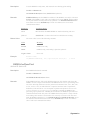
[1] All AC Current ranges have typical measurement capability of at least 20 kHz.
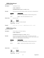
2.6 Leakage Measurement (SM2064)
Characteristics
• Burden Voltage: < 100 µV
• Test Voltage: Adjustable between -10V to +10V in 5mV steps
Accuracy ± (% of reading + Amps) [1]
Range
240 ηA
2.4 µA
24 µA
Full Scale
6-½ Digits
240.0000 ηA
2.400000 µA
24.00000 µA
Resolution
0.1 pA
1 pA
10 pA
24 hours
23°C ± 5°C
0.15 + 50pA
0.1 + 350pA
0.08 + 3nA
90 Days
23°C ± 5°C
0.2 + 65pA
0.15 + 500pA
0.12 + 4nA
[1] With Aperture set to ≥ 0.5 Sec, and within one hour from Zero (Relative control).
2.7 RTD Temperature Measurement (SM2064)
Signametrics
16
One Year 23°C
± 5°C
0.17 + 100pA
0.2 + 600pA
0.18 + 2nA
•
Ro: Variable from 10 Ω to 10 kΩ
•
Measurement Method: 4-Wire
•
Temperature units: Selectable oC or oF
RTD Type
0.01°C
Temperature
range
-150 to 650°C
Temperature Accuracy 23°C ± 5°C [1]
One Year
±0.06°C
500, 1 kΩ
0.01°C
-150 to 650°C
±0.03°C
Less than 12 Ω
0.01°C
-100 to 200°C
Higher than 90 Ω
0.01°C
-100 to 200°C
±0.18°C for temperatures ≤ 20°C, ±0.05°C
otherwise
±0.10°C for temperatures ≤ 20°C, ±0.05°C
otherwise
Ro (Ω)
Resolution
pt385, pt3911,
pt3916, pt3926
pt385, pt3911,
pt3916, pt3926
Cu (Copper)
100, 200 Ω
Cu (Copper)
[1] With Aperture of 0.5s and higher, using a 4-wire RTD. Measurement accuracy does not include
RTD probe error.
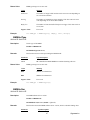
2.8 Thermocouple Temperature Measurement (SM2064)
•
Cold Junction Compensation: By Sensor measurement or S/W setting.
•
Cold Junction Temperature range: 0 oC to 50 oC
•
Cold Junction Sensor: Use SMX40T or SM40T Isothermal unit, or define sensor equation
•
Isothermal Block compatibility: SM4022, SM4042, SMX4032, SM40T, SMX40T
•
Temperature units: Selectable oC or oF
TC Type
B
E
J
K
N
R
S
T
Resolution
0.01°C
0.01°C
0.01°C
0.01°C
0.01°C
0.01°C
0.01°C
0.01°C
Maximum Temperature
[2]
2200°C
1200°C
2000°C
3000°C
3000°C
2700°C
3500°C
550°C
Temperature Accuracy 23°C ± 5°C [1]
One Year
±0.38 °C
±0.035 °C
±0.06 °C
±0.07 °C
±0.10 °C
±0.25 °C
±0.35 °C
±0.06 °C
[1] With Aperture of 0.5s and higher. Measurement accuracy does not include Thermocouple error.
[2] DMM Linearization temperature range may be greater than that of the Thermocouple device.
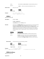
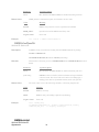
2.9 Additional Component Measurement Capability
2.9.1 Diode Characterization
•
Available DC current values 100 ηA, 1 µA, 10 µA, 100 µA and 1 mA.
•
SM2064 add variable current of 10 ηA to 12.5 mA
•
Typical Current Value Uncertainty 1%
•
Typical Voltage Value Uncertainty 0.02%
•
Maximum diode voltage compliance 4 V
2.9.2 Capacitance, Ramp Method (SM2064)
Accuracy ± (% of reading + Farads) [1]
17
Signametrics
Range
1,200 pF
12 ηF
120 ηF
1.2 µF
12 µF
120 µF
1.2 mF
12 mF
Full Scale
Reading
1,199.9 pF
11.999 ηF
119.99 ηF
1.1999 µF
11.999 µF
119.99 µF
1.1999 mF
50.000 mF
Resolution
0.1 pF
1 pF
10 pF
100 pF
1 ηF
10 ηF
100 ηF
1 µF
One Year
23°C ± 5°C
1.5 ± 0.25 pF
1.2 ± 5 pF
1.0
1.0
1.0
1.0
1.2
2
[1] Within one hour of zero, using Relative control. Accuracy is specified for values higher than 5% of the selected
range with the exception of the 1,200 pF range.
This Measurement is independent of set Aperture and Read Interval. If desired, the DMMSetCapsAveSamp()
function may be used to control measurement parameters. It is provided means to fine tune the measurement timing for
the application, trading off accuracy for speed.
Measurement time will vary as function of the set parameters, selected range and measured capacitance. The following are
measurement times associated with the default parameters, as range is selected.
Range
Input
Measurement Time
Measurement Rate (rps)
1,200 pF
5% of Scale
19.5 ms
51.3
1,200 pF
Full Scale
52.3 ms
19.1
5%
of
Scale
12 ηF
70.0 ms
14.3
Full Scale
12 ηF
118ms
8.5
5% of Scale
120 ηF
8.9 ms
112.4
Full Scale
120 ηF
127 ms
7.9
5% of Scale
1.2 µF
15.6 ms
64.1
Full Scale
1.2 µF
175 ms
5.7
5%
of
Scale
12 µF
14.1 ms
70.9
Full Scale
12 µF
480 ms
2.1
5% of Scale
120 µF
17.3 ms
57.8
Full Scale
120 µF
50.3 ms
19.9
1.2 mF
5% of Scale
52.6 ms
19.0
1.2 mF
Full Scale
151.5 ms
6.6
12 mF
5% of Scale
52.8 ms
18.9
12 mF
Full Scale
170 ms
5.9
Signametrics
18
2.9.3 Capacitance, In-Circuit Method (SM2064)
•
Adjustable Peak Voltages Stimulus 100mV to 1.3V
•
Minimum Parallel Load Resistance 100Ω
Accuracy ± (% of reading + Farads) [1]
Range
Full Scale
3-½ Digits
23.99 ηF
239.9 ηF
2.399 µF
23.99 µF
239.9 µF
2.399 mF
23.99 mF
24 ηF
240 ηF
2.4 µF
24 µF
240 µF
2.4 mF
24 mF
Resolution
10 pF
100 pF
1000 pF
10 ηF
100 ηF
1 µF
10 µF
One Year
23°C ± 5°C [2]
2.7 ± 100 pF
2.5 ± 500 pF
2.5 ± 5 ηF
[1] Within one hour of zero, using Relative control, and Caps Open-Cal operation
[2] Accuracy is specified for values higher than 5% of the selected range with the exception of the 2.4 ηF range.
Capacitance Measurement time is independent of set Aperture and Read Interval. It depends on range, and
capacitance.
2.9.4 Inductance Measurement (SM2064)
Range
Test frequency
24 µH
240 µH
2.4 mH
24 mH
240 mH
2.4 H
75 kHz
50 kHz
4 kHz
1.5 kHz
1 kHz
100 Hz
Full Scale
4 ½ Digits
33.000 µH
330.00 µH
3.3000 mH
33.000 mH
330.00 mH
3.3000 H
Resolution
1 ηH
10 ηH
100 ηH
1 µH
10 µH
100 µH
Accuracy 23°C ± 5°C
One Year [2]
3.0% + 500 ηH
2.0% + 3 µH
1.5% + 25 µH
1.5% + 200 µH
2.5 + 3 mH
3 + 35 mH
[1] Within one hour of zero, and Open Terminal Calibration.
[2] Accuracy is specified for values greater than 5% of the selected range.
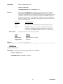
2.10 Time Measurements
2.10.1 Threshold DAC
•
The Threshold DAC is used for selecting a detection level, providing optimal frequency and
timing measurements even at extreme duty cycle values.
± (% of setting + volts)
Selected VAC
range [1]
Threshold range (DC
level)
240 mV
2.4 V
24 V
240 V
-1.0 V to +1.0 V
-10.0 V to +10.0 V
-100.0 V to 100.0 V
-400 V to 400 V
Threshold
DAC
resolution
0.5 mV
5.0 mV
50 mV
500 V
Highest allowed input
Vp-p
Typical one year setting
uncertainty
1.900 V
19.00 V
190.0 V
850.0 V
0.2% + 4 mV
0.2% + 40 mV
0.2% + 0.4 V
0.2% + 4 V
[1] This table should be used in conjunction with the AC volts section above.
19
Signametrics
2.10.2 Frequency and Period Measurement
ACV Mode
•
Input Impedance 1 MΩ with < 300 pF
Frequency Range
Resolution
Uncertainty is ±0.002% of
reading ± adder shown
Input Signal Range [1]
2 Hz - 100 Hz
1 mHz
4 mHz
100 Hz-1 kHz
10 mHz
20 mHz
1 kHz-10 kHz
100 mHz
200 mHz
10 kHz-100 kHz
1 Hz
2 Hz
100 kHz-300 kHz
1 Hz
5 Hz
10% - 200%
of range
10% - 200%
of range
10% -200%
of range
10% - 200%
of range
45% -200%
of range
[1] Input RMS voltage required for a valid reading. Do not exceed 250 V RMS input. For example, 10% -200%
of range indicates that in the 240 mVAC range, the input voltage should be 24 mV to 660 mV RMS.
ACI Mode
•
Input Impedance 10 Ω in the 3 mA and 30 mA ranges, 0.1 Ω in the 330 mA and 2.5 A ranges.
Frequency Range
Resolution
Uncertainty
Input Signal Range,
2.4 mA, 240mA Ranges
[1]
Input Signal Range,
24 mA, 2.4 A ranges
2 Hz - 100 Hz
1 mHz
0.01% ±4 mHz
10% -500%
of range
100 Hz-1 kHz
10 mHz
0.01% ±20 mHz
10% - 500%
of range
1 kHz-10 kHz
100 mHz
0.01% ±200 mHz
10% -500%
of range
10 kHz-500 kHz
1 Hz
0.01% ±2 Hz
10% - 500%
of range
50% -100%
of range
50% - 100%
of range
50% - 100%
of range
50% - 100%
of range
[1] Input current required to give a valid reading. For example, 10% -500% of range indicates that in the 3.3 mA
range, the input current should be 0.33 mA to 16.5 mA.
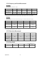
2.10.3 Duty Cycle Measurement
Frequency Range
2 Hz to 100 Hz
100 Hz to 1 kHz
1 kHz to 10 kHz
10 kHz to 100 kHz
Resolution
0.02%
0.2%
2%
20%
Typical Uncertainty is
±0.03% of reading ±
adder shown
Full scale reading
0.03%
0.3%
3%
20%
100.00 %
100.00 %
100.00 %
100.00 %
2.10.4 Pulse Width
± (% of reading + sec)
Polarity
Frequency range
Resolution
Width range
Positive or negative pulse
widths
2 Hz to 100 kHz
1 µs
2 µs to 1 s
Signametrics
20
Typical
Uncertainty
0.01 +/- 4 µs
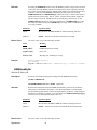
2.10.5 Totalizer
•
Active edge polarity: Positive or negative transition
•
Maximum count: 10^9
•
Allowed rate: 1 to 30,000 events per second
•
Uses Threshold DAC
2.11 Trigger Functions
2.11.1 External Hardware Trigger (at DIN-7 connector)
Trigger Input voltage level range
Trigger Pulse Width
Minimum trigger input current
Internal Reading Buffer
Isolation of trigger input
+3 V to +15 V activates the trigger.
Minimum = 1/Aperture + 50µS
1 mA
Circular; 80 or 120 readings depending on resolution.
±50 V from analog DMM inputs, and from chassis
earth ground.
2.11.2 Analog Threshold Trigger
•
•
•
•
•
•
•
•
•
Trigger point: Selectable positive or negative transition of set threshold.
Buffer type: Circular
Captures up to 120 post-trigger readings for apertures < 625uSec.
Captures up to 80 post-trigger readings for apertures > 625uSec.
Aperture range: 160ms to 625µS (to 2.5µS with SM2064)
Read Interval range: 1/Aperture to 65ms
User selects number of post-trigger readings.
The number of pre-trigger readings: buffer size – post-trigger count.
The number of cycles the circular filled, and the trigger point are retrievable.
2.11.3 Delayed Hardware Trigger
This function allows time for the signal to settle after a trigger has occurred.
It allows readings to be delayed up to 65mSec with 1µSec resolution.
It allows readings to be delayed up to 1s with 2µs resolutions.
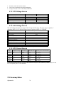
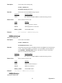
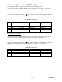
2.12 Measurement Aperture and Read Interval
Both Aperture and The Read Interval may be set. The range of values depend on the DMM model and its
mode of operation. For example, when using the internal buffer such as in External Trigger mode, the
Read Interval can be set smaller than in Command/Response operation. The time involved in processing
the measurement command and the post processing and transmission of the measurement results
constitute an overhead, which limits the minimum Read Interval to a value that is greater than the
Aperture. Setting it to zero (default) results in the fastest measurement rates at the selected Aperture. The
faster SM2064 has lower overhead and therefore a shorter minimum Read Interval than the SM2060. For
instance, with Aperture set to 625us and Read Interval set to zero, in command/response operation the
SM2060 measurement rate is about 1,090/s while that of the SM2064 is 1,370/s. This indicates overhead
of about 300µs for the SM2060 and 100µs for the SM2064.
The SM2064 has 31 A/D apertures available, ranging from 5 Seconds to 2.5µS. The following table contains all
available measurement apertures and the corresponding minimum read intervals and measurement rates.
Power Line Rejection
Command/Response
mode min. Read
21
H/W Trigger mode min. Read
Interval(s) / max meas. Rate
Signametrics
Interval(s) / max meas.
rate(Hz)
Aperture
60Hz 50Hz 400Hz
5.1200s [1]
5.121s / 0.2
√
√
√
5.0666s [1]
5.0677s / 0.2
√
2.08s [1]
2.081s / 0.5
√
√
2.0s [1]
2.001s / 0.5
√
√
√
1.06666s [1]
1.067s / 1
√
960ms [1]
0.9605s / 1
√
√
533.33ms [1]
533.6ms / 2
√
480ms [1]
480.2ms / 2
√
√
266.666ms [1] √
268ms / 4
160.0ms
166ms / 6
√
√
√
133.33ms
134ms / 8
√
80.00ms
80.4ms / 13
√
√
66.6667ms
67.2ms / 15
√
40.00ms
40.4ms / 25
√
√
33.333ms
33.643ms
/ 29.72
√
20.00ms
20.098ms
/ 49.76
√
√
16.6667ms
16.77ms / 59.6
√
10ms
10.094ms / 99
8.333ms
8.422ms / 119
5ms
5.109ms / 195
4.16667ms
4.265ms / 234
2.5ms
2.598ms / 385
2.0833ms
2.177ms / 458
1.25ms
1.344ms / 744
1.0417ms
1.133ms / 880
625µS
719µs / 1,390
520.83µS
617µs / 1,625
312.5µS
410µs / 2,445
260.42µS
355µs / 2,825
130.21µS
223µs / 4,475
2.5µS
47µs / 21,600
[1] Not available with any of the Triggered modes.
Signametrics
22
(Hz)
N/A
N/A
N/A
N/A
N/A
N/A
N/A
N/A
N/A
160.3 ms / 6
133.5 ms / 8
80.2 ms / 13
66.713 ms / 15
40.32 ms / 24.8
33.38 ms / 30
20.33 ms / 50
16.89 ms / 59
10.25 ms / 97
8.503 ms / 115
5.187 ms / 185
4.274 ms / 220
2.614 ms / 350
2.216 ms / 410
1.380 ms / 625
1.158 ms / 864
728 µs / 1,370
622 µs / 1,610
414 µs / 2,445
358 µs / 2,825
217 µs / 4,660
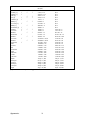
45 µs / 22,200
The SM2060 has are 26 A/D apertures available, ranging from 5 Seconds to 625uSec. The following
table contains all available measurement apertures corresponding minimum read intervals and
measurement rates.
Power Line Rejection
Command/Response
mode min. Read
Interval(s) / max meas.
rate(Hz)
Aperture
60Hz 50Hz 400Hz
5.1200s [1]
5.121s / 0.2
√
√
√
5.0666s [1]
5.0677s / 0.2
√
2.08s [1]
2.081s / 0.5
√
√
2.0s [1]
2.001s / 0.5
√
√
√
1.06666s [1]
1.067s / 1
√
960ms [1]
0.9605s / 1
√
√
533.33ms [1]
533.6ms
/2
√
480ms [1]
480.2ms
/2
√
√
266.666ms [1] √
268ms / 4
160.0ms
166ms / 6
√
√
√
133.33ms
134ms / 8
√
80.00ms
80.4ms / 13
√
√
66.6667ms
67.2ms / 15
√
40.00ms
40.4ms / 25
√
√
33.333ms
33.7ms / 30
√
20.00ms
20.35ms / 50
√
√
16.6667ms
16.9ms / 59
√
10ms
10.36ms / 97
8.333ms
8.68ms / 115
5ms
5.36ms / 185
4.16667ms
4.52ms / 220
2.5ms
2.86ms / 350
2.0833ms
2.44ms / 410
1.25ms
1.6ms / 625
1.0417ms
1.39ms / 719
625µS
917µs / 1,090
[1] Not available with any of the Triggered modes.
H/W Trigger mode min. Read
Interval(s) / max meas. Rate
(Hz)
N/A
N/A
N/A
N/A
N/A
N/A
N/A
N/A
N/A
160.3 ms / 6
133.5 ms / 8
80.2 ms / 13
66.713 ms / 15
40.32 ms / 24.8
33.38 ms / 30
20.33 ms / 50
16.89 ms / 59
10.25 ms / 97
8.503 ms / 115
5.187 ms / 185
4.274 ms / 220
2.614 ms / 350
2.216 ms / 410
1.380 ms / 625
1.158 ms / 864
728 µs / 1,370
Precise control of the measurement timing and line frequency rejection can be accomplished by controlling the Read
Interval and Aperture. Line rejection is dictated by the Aperture, and the duration of measurement is controlled with
Read Interval.
Read Interval can be programmed in µs increments for values up to 65ms, and in 20µs increments to 1 second.
Figure 2-1: Time frame of a single measurement.
2.13 Source Functions (SMX2064)
23
Signametrics
•
•
•
Isolated to 300 V DC from the Chassis
Current can be paralleled with multiple SMX2064s
Voltage can be put in series with multiple SMX2064s
2.13.1 DC Voltage Source
Parameter
Output Voltage range
Typical Current source/sink at 5V output
DAC resolution
Accuracy 23°C ± 10°C One Year
Typical settling time
Typical source resistance
Closed Loop [1]
Open Loop
-10.000 V to +10.000 V
5 mA
5 mA
18 bits
12 bits
1.0% ± 35 mV
0.015% ± 350 µV
3 S (rate set to 2/s)
1 ms
250 Ω
[1] An Aperture set to 133ms or higher is required for the closed loop mode.
2.13.2 AC Voltage Source
The AC Voltage source has two ranges. 900 mV range and 8V range. The lower range is capable of
generating 50mV to 9.3V while the higher range can generate 300mV to 7.2V RMS.
Parameter
Ranges
Output Voltage, sine wave
DAC resolution
Typical Current Drive at 3.5V RMS
Accuracy 18°C to 28°C One Year
Typical settling time (f-out > 40 Hz)
Typical source resistance
Frequency range / resolution
SFDR (spurious free dynamic range)
THD (total harmonic distortion)
Frequency stability
Specification
900mV and 8V
30mV to 7.2 V RMS (0.14 to 20.0V peak-to-peak)
12 bits
3 mA RMS
ACV spec + 0.8% ± 20 mV
0.5 s
250 Ω
10 Hz to 100 kHz / 10 mHz
60dBc
59dBc
100 ppm ± 10 mHz
[1] 166ms or higher Aperture is required for proper closed loop mode.
2.13.3 DC Current Source
Compliance Voltage
Resolution [1]
Minimum level
Accuracy 23°C ± 10°C One Year
1.25 µA
4.2 V
500 pA
1 ηA
1% + 10 ηA
12.5 µA
4.2 V
5 ηA
10 ηA
1% + 100 ηA
125 µA
4.2 V
50 ηA
100 ηA
1% + 500 ηA
1.25 mA
4.2 V
500 ηA
1 µA
1% + 5 µA
12.5 mA
1.5 V
5 µA
10 µA
1% + 50 µA
Range
[1] Resolution without Trim DAC. The use of the Trim DAC can improve the resolution by a factor of 10, but it has
to be set separately since it is not calibrated.
2.14 Accuracy Notes
Signametrics
24
Important: all accuracy specifications for DCV, Resistance, DCI, ACV, and ACI apply for the time periods shown
in the respective specification tables. To meet these specifications, Self Calibration must be performed once a day or
as indicated in the specification table. This is a simple software operation that takes a few seconds. It can be
performed by calling Windows command DMMCal(), or selecting S-Cal in the control panel.
These products are capable of continuous measurement as well as data transfer rates of up to 20,000 readings per
second (rps). In general, to achieve 7-1/2 Digits of resolution, the Aperture should be set to 0.5s or a higher value.
6-1/2 digit resolution requires at least 10ms Aperture. For 5-1/2 use at least 625us Aperture.
2.15 Other Specifications
Temperature Coefficient over 0°C to 50°C Range
• Less than 0.1 x accuracy specification per °C At 23C ± 5°C
Aperture (user selectable)
• 625 µs to 2s in 26 discrete values, SM2060 (approx. 0.5 to 1,400 readings per second)
• 2.5µs to 2s in 31 discrete values, SM2064 (approx. 0.5 to 20,000 readings per second)
• In Triggered modes Aperture is limited to 160ms or shorter.
Read Interval (user selectable)
• 47µs to 65ms, 1µs steps in Trigger modes, SM2064
• 730µs to 65ms, 1us steps in Trigger modes, SM2060
• 47µs to 1s, 1µs steps below 65ms, in command/response modes, SM2064
• 916µs to 1s, 1µs steps below 65ms, in command/response modes, SM2060
Hardware Interface
Single PCI slot
Overload Protection (voltage inputs)
330 VDC, 250 VAC
Isolation
330 VDC, 250 VAC from Earth Ground
Maximum Input (Volt x Hertz)
8x10⁶ Volt x Hz normal mode input (across Voltage HI &
LO).
1x10⁶ Volt x Hz Common Mode input (from Voltage HI or
LO relative to Earth Ground).
Safety
Designed to IEC 1010-1, Installation Category II.
Calibration
Calibrations are performed by Signametrics in a computer at
23°C internal temperature rise. All calibration constants are
stored in a text file.
Temperature Range Operating
-10°C to 65°C
Temperature Range Storage
-40°C to 85°C
Size
SM2060, SM2064: 4.5” X 8.5” (PCI format)
SMX2060, SMX2064: Single 3U PXI or CompactPCI slot
DMM Internal Temperature sensor accuracy
±1°C (SM2064)
Power
+5 volts, 300 mA maximum
Note: Signametrics reserves the right to make changes in materials, specifications, product functionality, or
accessories without notice.
25
Signametrics
Accessories
Several accessories are available for the SM2060 series DMM’s, which can be purchased directly from
Signametrics, or one of its approved distributors or representatives. These are some of the accessories available:
•
DMM probes SM-PRB ($15.70)
•
DMM probe kit SM-PRK ($38.50)
•
Deluxe probe kit SM-PRD ($95.00).
•
Shielded SMT Tweezers Probes SM-PRSMT ($24.90).
•
Multi Stacking Double Banana shielded cable 36” SM-CBL36 ($39.00).
•
Multi Stacking Double Banana shielded cable 48” SM-CBL48 ($43.00).
•
Mini DIN Trigger, 6-Wire Ohms connector SM2060-CON7 ($14.00).
•
Lab View VI’s library SM204x.llb (free).
•
Extended 3 Year warrantee (does not include calibration) $150.00 for SM2060 and SMX2060, $240 for the
SM2064 and SMX2064.
Signametrics
26
3.0 Getting Started
After unpacking the DMM, please inspect for any shipping damage that may have occurred, and report any claims
to your transportation carrier.
The DMM is shipped with the Digital Multimeter module; Installation CD and a floppy disk that contain the
calibration and verification files. Also included is the Certificate of Calibration.
3.1 Setting the DMM
The SM2060 series DMM’s are PCI plug-and-play devices and do not require any switch settings, or other
adjustments prior to installation.
The SM60CAL.DAT file supplied with your DMM has a unique calibration record for that DMM (See
"Calibration" at the end of this manual.) When using multiple DMM’s in the same chassis, the SM60CAL.DAT
file must have a calibration record for each DMM. Append the unique calibration records of each DMM into one
SM60CAL.DAT file using a text editor such as Notepad. The default location for the SM60CAL.DAT file is at
the root directory C:\.
3.2 Installing the DMM Module
Warning
To avoid shock hazard, install the DMM only into a personal computer that has its power line connector
connected to an AC receptacle with an Earth Safety ground.
After installation, check to see that no loose wires or ribbon cables infringe upon any of the internal circuits
of the DMM, as this may apply measurement voltages to your computer, causing personal injury and/or
damage to your computer!
Caution: Only install the DMM module with the power turned OFF to the PC!
Use extreme care when plugging the DMM module(s) into a PCI bus slot. If possible, choose an empty slot away
from any high-speed boards (e.g. video cards) or the power supply. Please be patient during the installation
process! The DMM comes with 4 safety-input jacks. Because of their necessary size, they are a tight fit in many
PC chassis. Insert the bracket end of the DMM into your PC first, watching for any interference between the safety
input jacks and your PC chassis. “Sliding” the bracket end of the DMM into the chassis may be helpful. Be
patient! You should only have to install it once!
3.3 Installing the Software
It is recommended that you first plug in the DMM into the PC chassis, than turn on the computer power. The first
time you power up your computer with the DMM installed, your computer will detect it as new hardware and
prompt you for a driver. The driver your computer requires is located on the installation CD (SM2060.INF).
Following the above driver installation, run the ‘SETUP’ program provided on the CD. This takes care of all
installation and registration requirements of the software. If you are installing the DMM on a computer that had an
SM2060 series install in it, you should first uninstall the old software. Also make sure you backup and remove the
old calibration record (SM60CAL.DAT). For a clean reinstallation remove all INF files containing reference to the
Signametrics DMM. Depending on operating system, these files will be located at Windows\inf, Windows\inf\other
or WINNT\inf. The files will be named Oemx.INF where x is 0,1,2,… and/or SIGNAMETRICSSM2060.INF. If
present, these files will prevent “Found New Hardware” wizard from detecting the new DMM.
27
Signametrics
3.4 DMM Input Connectors
Before using the DMM, please take a few moments and review this section to understand where the voltage,
current, or resistance and other inputs and outputs should be applied. This section contains important
information concerning voltage and current limits. Do not exceed these limits, as personal injury or damage
to the instrument, your computer or application may result.
Figure 3-1. The DMM input connectors.
V, Ω + This is the positive terminal for all Volts, 2WΩ, capacitance, diode and inductance measurements, and for
sourcing of VDC, VAC and IDC. It is also the Source HI for 4WΩ measurements. The maximum input across V, Ω
+ and V, Ω - is 300 VDC or 250 VAC when in the measuring mode. When in the sourcing mode, the maximum
input allowed before damage occurs is 100 volts.
V, Ω - This is the negative terminal for all Volts, 2WΩ, capacitance diode and inductance measurements, and or
sourcing of VDC, VAC and IDC. It is also the Source LO for 4WΩ. Do not float this terminal or any other
DMM terminal more than 300 VDC or 250 VAC above Earth Ground. (Also, see Trig, 6W Guard below.)
I + This is the positive terminal for all Current measurements. It is also the Sense HI for 4WΩ measurements and
6WΩ guarded measurements. The maximum input across I, 4WΩ + and I, 4WΩ - is 2.5 A. Do not apply more
than 5 V peak across these two terminals!
I – This is the negative terminal for all Current measurements. In the Current modes, it is protected with a 2.5 A,
250 V Fast Blow fuse (5 x 20 mm). It is also the Sense LO for 4WΩ measurements and 6WΩ guarded
measurements. V, Ω - and I, 4WΩ - should never have more than 5 V peak across them.
Signametrics
28
TRIG / GUARD Both the Trigger and Guard functions are at the DIN-7 connector. This group of pins includes
the positive and negative hardware trigger input lines and the two SM2064 Guarded Measurement Force and Sense
signals. The external trigger initiates reading(s) into the onboard buffer, and the 6W guard signals facilitate incircuit resistor measurements by means of isolating a loading node. The DIN-7 plug can be ordered from
Signametrics and is also available at many electronic hardware distributors. The connector is generically referred to
as a mini DIN-7 male. The trigger signal should be in the range of 3 V to 12 V peak. The two 6W guard signals
should never have more than 5 V peak across them.
Warning! The DIN connector pins are protected to a maximum of 35 V with respect to the PC chassis and
any other DMM terminal. Do not apply any voltages greater than 35 V to the DIN connector pins. Violating
this limit may result in personal injury and/or permanent damage to the DMM.
DIN-7, Pin number
2
7
4
1
6
Function
Sync output, referenced to pin 4
External Trigger input, Positive
Trigger and Sync Common
Guard Source (SM2064)
Guard Sense (SM2064)
DIN-7 Connector Pin Description, view from bracket side.
3.5 Starting the Control Panel
You can verify the installation and gain familiarity with the DMM by exercising its measurement functions using
the Windows based Control Panel. To run the control panel, double click the “SM2064.EXE” icon. If you do not
hear the relays click, it is most likely due to an installation error. Another possible source for an error is that the
SM60CAL.DAT file does not correspond to the installed DMM.
When the DMM is started the first time, using the provided control panel (SM2064.EXE), it takes a few extra
seconds to extract its calibration data from the on-board store, and write it to a file C:\SM60CAL.DAT
The Control Panel is operated with a mouse. All functions are accessed using the left mouse button. When the
DMM is operated at very slow reading rates, you may have to hold down the left mouse button longer than usual for
the program to acknowledge the mouse click.
29
Signametrics
Note: The SM2060 front panel powers up in DCV, 0.5s Aperture, 0 Read Interval and 240 V range. If the DMM is
operated in Autorange, with an open input, it will switch between the 2.4V and 24V ranges every few seconds, as a
range change occurs. This is perfectly normal with ultra high impedance DMM’s such as the SM2060. This
phenomenon is caused by the virtually infinite input impedance of the 2.4V DC range. On these ranges, an open
input will read whatever charge is associated with the signal conditioning of the DMM. As this electrical charge
changes, the SM2060 will change ranges, causing the range switching. This is normal.
3.6 Using the Control Panel
Figure 3-2. The Control Panel for the SM2064. The three main groups include Measure, Source and
Range buttons. The Range buttons are context sensitive such that only “240m, 2.4, 24, 240 and 330
appear when in AC Voltage Function is selected, and 2.4m, 24m, 240m and 2.4 appear when AC
Current functions is selected, etc.
Note: All of the controls described below correspond to their respective software function, which can be invoked
within your control software or as objects in a visual programming environment. The software command language
of the SM2060 provides a powerful set of capabilities. Some of the functions are not included in the control panel,
but are in the software.
DC/AC This function switches between DC and AC. This is applicable for the following DMM functions:
Voltage, Current, and Voltage-Source. If Voltage-Source is the function presently in use, the Source control under
the Tools menu can be used to set frequency and amplitude in ACV, and amplitude only in DCV and DCI.
Relative This is the Relative function. When activated, the last reading is stored and subtracted from all
subsequent readings. This is a very important function when making low-level DCV measurements, or in 2WΩ.
For example, when using 2WΩ, you can null out lead resistance by shorting the leads together and clicking on
Relative. When making low level DC voltage measurements (e.g., in the µV region), first apply a copper short to
the V,Ω + & - input terminals, allow the reading to stabilize for a few seconds, and click on Relative. This will
correct for any offsets internal to the SM2060. The Relative button can also be used in the Percent and dB
deviation displays (shown below), which are activated using the Tools in the top menu.
The Min/Max box can be used to analyze variations in terms of Min, Max,
Percent and dBV. This display can be activated by selecting the
Min/Max/Deviation from the Tools menue. For instance, testing a circuit
bandwidth with an input of 1V RMS, activate the Relative function with the
frequency set to 100Hz, than sweep gradually the frequency, and monitor the
percent deviation as well as the dBV error and capture any response anomalies
with the Min/Max display. The left display indicates peaking of 2.468% (0.21
dBV) and maximum peaking in the response of +56.24mV and a notch of –
10.79mV from the reference at 100Hz.
Aperture Box: Controls the SM2060 reading aperture. As aperture decreases, the measurement noise increases.
For best accuracy set to the longest aperture acceptable for the application. Also consider the line frequency (50/60
Hz) of operation when setting it, as certain apertures have better noise rejection at either 50 or 60 Hz. (See
Signametrics
30
“Specifications” for details.). When measuring RMS values, there is no point setting the Read Interval (1/rate) to a
value shorter than 0.16s since the RMS circuitry has a settling time that is greater.
Range: Can be set to Autorange or manual by clicking on the appropriate range in the lower part of the Windows
panel. Autoranging is best used for bench top application and is not recommended for an automated test
application due to the uncertainty of the DMM range, as well as the extra time for range changes. Locking a range
is highly recommended when operating in an automated test system, especially to speed up measurements. Another
reason to lock a range is to control the input impedance in DCV. The 240 mV and 2.4 V ranges have virtually
infinite input impedance, while the 24 V and 240 V and 330 V ranges have 10 MΩ input impedance.
S_Cal: This function is the System Calibration that corrects for internal gain, scale factor and zero errors. The
DMM does this by alternatively selecting its local DC reference and a zero input. It is required at least once every
day to meet the SM2060 accuracy specifications. It is recommended that you also perform this function whenever
the external environment changes (e.g. the temperature in your work environment changes by more than 5°C, or the
SM2064 on board temperature sensor indicates more than a 5°C change). This function takes less than a few
seconds to perform. Disconnect all leads to the DMM before doing this operation. Keep in mind that this is not a
substitute for periodic calibration, which must be performed with external standards.
ClosedLoop: This check box selection is used in conjunction with the AC and DC Voltage-Source functions of the
SM2064. When checked, the DMM monitors the output level and continuously applies corrections to the output
level. When not checked, the DMM is a 12-bit source vs. 16 bits in the ClosedLoop mode.
OpenCal: This check box selection is used in conjunction with inductance measurement. It is necessary to perform
Open Terminal Calibration using this control, prior to measuring inductance. This function characterizes both the
internal DMM circuitry as well as the probe cables. To perform OpenCal, attach the probe cables to the DMM,
leaving the other end of the probe cables open circuited. Then, activate the OpenCal button.
Sources Panel: There are three function buttons in the Source group (SM2064 only). The V, I, LEAK buttons
select one of three source functions, Voltage (DC and AC), IDC and Leakage. The Sources Panel is automatically
enabled when one of the source functions is enabled. It can also be invoked using the Sources Panel selection
under the Tools menu. This panel allows the entry of values for all of the source functions, including Leakage.
The V-OUT Scroll bar and Text box are used to
set the Voltage for DC and AC Volts as well as
for Leakage. When sourcing ACV, the voltage is
in RMS and the FREQ. Scroll bar and Text box
control the frequency of the source. It is also
used to control inductance frequency. When
sourcing DC current, use the I-OUT set of
controls. When measuring timing or freqeuncy
the THRESH set of controls is used for
comperator threshold. All of the source controls
are context sensitive and will be enabled when
31
Signametrics
4.0 DMM Operation and Measurement Tutorial
Most of the SM2060 measurement functions are accessible from the Windows Control Panel (Figure above). All of
the functions are included in the Windows DLL driver library. To gain familiarity with the SM2060 series DMM’s,
run the Windows ‘SETUP.EXE’ to install the software, then run the DMM, as described in the previous section.
This section describes in detail the DMM’s operation and measurement practices for best performance.
4.1 Voltage Measurement
Measures from 0.1 µV to 330 VDC or 250 VAC. Use the V, Ω + and V, Ω - terminals, being certain to always leave
the I+, I- and DIN-7 terminals disconnected. Use the AC/DC button on the Control Panel to switch between AC
and DC.
Making Voltage Measurements is straightforward. The following tips will allow you to make the most accurate
voltage measurements.
4.1.1 DC Voltage Measurements
When making very low-level DCV measurements (<1 mV), you should first place a copper wire shorting plug
across the V, Ω + and V, Ω - terminals and perform Relative function to eliminate zero errors before making your
measurements. A common source of error can come from your test leads, which can introduce several µVolts of
error due to thermal voltages. To minimize thermal voltaic effects, after handling the test leads; you should wait a
few seconds before making measurements. Signametrics offers several high quality probes that are optimal for lowlevel measurements.
Note: The SM2060 front panel powers up in DCV, 0.5s aperture, 240 V range. If the DMM is operated in
Autorange, with an open input, The DMM will keep changing ranges. This is perfectly normal with ultra high
impedance DMM’s such as the SM2060. The virtually infinite input impedance of the 240 mV and 2.4 V DCV
ranges causes this phenomenon. On these ranges, an open input will read whatever charge is associated with the
signal conditioning of the DMM. As this electrical charge accumulates, the SM2060 will change ranges.
4.1.2 True RMS AC Voltage Measurements
ACV is specified for signals greater than 1mV, from 10 Hz to 100 kHz. The ACV function is AC coupled, and
measures the true RMS value of the waveform. As with virtually all true-RMS measuring meters, the SM2060 may
not read a perfect zero with a shorted input. This is normal.
ACV measurements, if possible, should have the NEUTRAL or GROUND attached to the SM2060 V,Ω - terminal.
See Figure 4-1, below. This prevents any “Common Mode” problems from occurring (Common Mode refers to
floating the SM2060 V,Ω LO above Earth Ground.) Common Mode problems can result in noisy readings, or even
cause the PC to hang-up under high V X Hz input conditions. In many systems, grounding the source to be
measured at Earth Ground (being certain to avoid any ground loops) can give better results.
The settling time and low end bandwidth of the RMS function are effected by the status of the Fast RMS control
circuit. When fast RMS is selected, the RMS settling time is about 10 times faster, but the low end frequency is
significantly increased.
Signametrics
32
Figure 4-1. Make Voltage ACV measurements with the source ground attached to the SM2060 V,Ω - to
minimize “Common Mode” measurement problems.
4.1.3 AC Peak-to-Peak and Crest Factor (SM2064)
Measurement of Peak-to-Peak, Crest Factor and AC Median values requires a repetitive waveform between 30 Hz
and 100 kHz. The DMM must be in AC voltage measurement mode, with the appropriate range selected. Knowing
the Peak-to-Peak value of the waveform is useful for setting the Threshold DAC (described below). This latter
function is a composite function, and may take over 10 seconds to perform.
4.1.4 AC Median Value Measurement (SM2064)
To better understand the usage of this function, you should note that the DMM makes all AC voltage measurements
through an internal DC blocking capacitor. The voltage is thus “AC coupled” to the DMM. The measurement of
the Median value of the AC voltage is a DC measurement performed on the AC coupled input signal. This
measurement returns the mid-point between the positive and negative peak of the waveform. The Median value is
used for setting the comparator threshold level for best counter sensitivity and noise immunity. (It is difficult to
measure the frequency of a low duty cycle, low amplitude AC signals since there is DC shift at the comparator input
due to the internal AC coupling. The SM2064 overcome this problem by allowing you to set the comparator
threshold level). For further information on the usage of AC Median value and Peak-to-Peak measurements, and
the Threshold DAC, see the “Frequency and Timing Measurements” section below.
This function requires a repetitive signal. The DMM must be in AC voltage measurement mode, with the
appropriate range selected.
4.2 Current Measurements
The SM2060 measures AC and DC currents between 100 ηA and 2.5 A. Use the +I, 4WΩ terminals, being certain
to always leave the V,Ω + & - terminals disconnected. Use the AC/DC button to switch between AC and DC. The
AC current is an AC coupled True RMS measurement function. See figure 4-2 for connection.
The Current functions are protected with a 2.5 A, 250 V fuse. The 2.4mA and 24mA ranges utilize a 10Ω shunt,
while the 240mA and 2.4A ranges use a 0.1Ω shunt. In addition to the shunt resistors, there is some additional
parasitic resistance in the current measurement path associated with the fuse and the internal wiring. The result is a
burden voltage of up to about 250mV.
33
Signametrics
4.2.1 Extended DC Current Measurements (SM2064)
In addition to the 2.4mA, 24mA, 240mA and 2.4A, the SM2064 has also four DC current ranges; 240nA, 2.4uA,
24uA and 240uA ranges. The lower three ranges are implemented with a “Virtual Zero Shunt” technology,
commonly associated with specialized Micro Amp meters. It has an ultra low noise low leakage that renders it
useful for measuring down to few Pico-amperes. This means that super low currents from such circuits as Current
output DACs of such devices as heart pace makers, or low semiconductor leakages can be measured with practically
no voltage drop.
In order to measure down to Pico Amperes it may be necessary to guard the terminals as described in the guarding
section of this manual (4.3.8 Guarding High Value Resistance Measurements (SM2064)).
Warning! Applying voltages greater than 35 V to the I+, I- terminals can cause personal injury and/or
damage to your DMM and computer! Think before applying any inputs to these terminals!
Figure 4-2. AC and DC Current measurement connection.
4.2.2 Improving DC Current Measurements
When making sensitive DC current measurements disconnect all terminals not associated with the measurement.
User the Relative function while in the desired DC current range to zero out any residual error. Using the S-Cal
(DMMCalibrate ()) prior to activating Relative will improve accuracy further. Although the SM2060 family is
designed to withstand up-to 2.4A indefinitely, be aware that excessive heat may be generated when measuring
higher AC or DC currents. If allowed to rise this heat may adversely effect subsequent measurements. In
consideration with this effect, it is recommended that whenever practical, higher current measurements be limited to
short time intervals. The lower two ranges of DC current may be effected by relay contamination. If the
measurements seem unstable or high, while in IDC measurement, apply between 20mA and 50mA DC to the
current terminals and clean the K2 relay using the DMMCleanRelay(0, 2, 200). Repeat this until the measurements
are stable.
4.2.3 DC Current Measurements at a specific voltage
The leakage measurement function can be used to measure low-level currents at a specific voltage. This
function uses the top and bottom terminals of the SM2064. It measures low level DC currents with a
specified DC voltage applied to the DUT.
Signametrics
34
4.3 Resistance Measurements
Resistance is measured using eight (six in the SM2060) precision current sources, with the DMM displaying the
resistance value. Most measurements can be made in the 2-wire mode. The 4-wire ohms is used to make low value
resistance measurements. All resistance measurement modes are susceptible to Thermo-Voltaic (Thermal EMF)
errors. See section 4.3.5 for details.
4.3.1 2-Wire Ohm Measurements
The DMM measure using 240Ω to 24 MΩ ranges. The SM2064 adds 24 Ω and 240 MΩ ranges, as well as extended
resistance to 100 GΩ. Use the V,Ω+, V,Ω- terminals for this function. Be certain to disconnect the I+, I- terminals
in order to reduce leakage, noise and for better safety.
Most resistance measurements can be made using the simple 2-wire Ohms method. Simply connect V,Ω+ to one
end of the resistor, and the V,Ω- to the other end. If the resistor to be measured is less than 30 kΩ, you should null
out any lead resistance errors by first touching the V,Ω+ and V,Ω- test leads together and then performing a
Relative function. If making measurements above 300 kΩ, you should use shielded or twisted leads to minimize
noise pickup. This is especially true for measurements above 1 MΩ.
You may also want to control the Ohms current used in making resistance measurements. (See the Specifications
section, "Resistance, 2-wire and 4-wire", for a table of resistance range vs. current level.) All of the Ohms ranges of
the SM2060 have enough current and voltage compliance to turn on diode junctions. For characterizing
semiconductor part types, use the Diode measurement function. To avoid turning on a semiconductor junction, you
may need to select a higher range (lower current). When checking semiconductor junctions, the DMM displays a
resistance value linearly related to the voltage across the junction.
For applications requiring voltage and current controlled resistance measurements, use the Extended Resistance
Measurement function as well as active guarding is available with the SM2064.
4.3.2 4-Wire Ohm Measurements
4-wire Ohms measurements are advantageous for making measurements below 330 kΩ, eliminating lead resistance
errors. The Voltage (V,Ω) Input terminals serve as a current source to stimulus the resistance, and the I, 4WΩ Input
terminals are the sense inputs. The Source + and Sense + leads are connected to one side of the resistor, and the
Source - and Sense - leads are connected to the other side. Both Sense leads should be closest to the body of the
resistor. See Figure 4-3.
4-wire Ohm makes very repeatable low ohms measurements, from 100 µΩ (10 µΩ for SM2064) to 330 kΩ. It is
not recommended to use 4WΩ when making measurements above 100 kΩ, although 4-wire ohms measurements are
facilitated up to 330 kΩ. 4-wire measurements are disabled above 330 kΩ since the extra set of leads can actually
degrade the accuracy, due to additional leakage and noise paths.
35
Signametrics
Figure 4-3. The I- and I+ sense leads should be closest to the body of the resistor when making 4WΩ
measurements.
4.3.3 Using Offset Ohms function (SM2064)
Inadvertent parasitic leakage currents, Thermo-voltaic voltages and other sources of voltage errors in a circuit can
be the cause of inaccuracies in resistance measurements. This is common particularly when making measurements
of active circuit. Many users, unaware of the above issues, select very poor switching systems prone to high
Thermal Errors that introduces some very high offset voltages, be it in 2-Wire or 4-Wire measurements. Offset
Ohms can alleviate some of this error. Enabling it can also be used to measure internal resistance of low value
voltage sources such as various batteries, low voltage power supplies and sensors. Use the normal 2-Wire or 4Awire Ohms connection, and set the Offset Ohms to the enabled or disabled state using the DMMSetOffsetOhms()
function. When set TRUE, the read interval will be twice as set. Both negative and positive polarity voltages can be
corrected as long as the total voltage including the resistance measurement voltage plus the parasitic voltage are less
than 0.5V. To calculate this voltage consult the specification part of this manual for the specific current for each
Ohms range. The default value of this function is FALSE. This function is implemented only with the SM2064.
4.3.4 6-wire Guarded Resistance Measurement (SM2064)
The SM2064 provides a guarded 6-wire resistance measurement method. It is used to make resistance
measurements when the resistor-under-test has other shunting paths, which can cause inaccurate readings. This
method isolates the resistor-under-test by maintaining a guard voltage at a user-defined node. The guard voltage
prevents the shunting of the DMM Ohms source current from the resistor-under-test to other components. The
Guard Source and Guard Sense terminals are provided at pins 1 and 6 of the DIN connector respectively.
Warning! The DIN connector pins are only protected to a maximum of 35 V with respect to the PC chassis
or any other DMM terminal. Do not apply any voltages greater than 35 V to the DIN connector pins.
Violating this limit may result in personal injury and/or permanent damage to the DMM.
Example: Assume a 30 kΩ resistor is in parallel with two resistors, a 510 Ω and a 220 Ω, which are connected in
series with each other. In a normal resistance measurement, the 510 Ω and 220 Ω would “swamp” the measurement
shunting most of the DMM Ohms source current. By sensing the voltage at the top of the 30 kΩ, and then applying
this same voltage to the junction of the 510 Ω and 220 Ω, there is no current flow through the shunting path. With
this “guarding”, the SM2064 accurately measures the 30 kΩ resistor.
Signametrics
36
Figure 4-4. 6-wire guarded in-circuit ohms measurement configuration.
The current compliance of the Guard Force is limited to a maximum of 20 mA and is short circuit protected. The
resistor connected between the low of the 4-wire terminals and the guard point is the burden resistor, or Rb. Due to
the limited guard source current, this resistor can not be lower than Rbmin: Rbmin = Io * Rx / 0.02, where Io is the
ohms source current for the selected range, and Rx is the resistance being measured. For example, selecting the 330
Ω range and measuring a 300 Ω resistor imposes a limit on Rb of at least 15 Ω or greater. Since the top burden
resistor, Ra, does not have this limit imposed on it, selecting the measurement polarity, Ra can become Rb and vise
versa. For cases where this limit is a problem, simply set the measurement polarity such that Ra is the higher of the
two burden resistors.
To measure values greater than 330 kΩ using the 6-wire guarded method, it is necessary to select the 2-wire ohms
function, and maintain the 6-wire connection as in Figure 4-4 above.
4.3.5 Extended Resistance Measurements (SM2064)
The Extended Resistance measurement function complements the standard resistance measurement. While the
standard resistance measurement forces a constant current, this function forces a variable voltage. It is ratiometric
in its operation, meaning it is using internal precision resistors to establish references for the various ranges. The
maximum test current is defined by the selected range. Negative Over-Range is reached when the test current
exceeds this limit. Positive Over-Range is declared when the current is lower than 0.04% of the current limit. The
test current is equal to the set test voltage divided by the measured resistance value.
Ranges are defined in terms of their current limit rather than resistance. The lowest range’s current limit is set at
24µA, therefore the lowest resistance it can measure with the test voltage programmed to 10V, is about 400k. With
the test voltage set to 0.1V the minimum value is about 4k. The next range’s limit is 2.4µA which corresponds with
4M at 10V and 40k with 0.1V. The highest range current is limited to 240nA, which implies that the lowest
resistance it can measure with 10V source is 40M and the lowest resistance it can measure with 0.1V is 400k. The
highest range practical measurement limit is as high as 10GΩ. The connection topology with optional active
guarding is depicted in Figure 4-7.
Set the test voltage using the DMMSetDCVSource() function. Due to the availability of a higher test voltages than
is available with the normal resistance function, as well as the ratiometric method, this measurement function is best
for high value resistors such as measuring leaky cables. Further benefit in setting a specific test voltage is to prevent
turning on of semiconductor junctions while testing high value resistors. The combined ability to limit both voltage
and current is significant in test applications where the destruction of a delicate sensor is a concern. The built-in
voltage source can be set between -10V and +10V. Also consider that with lower voltages, there is increase in
measurement noise. For instance measuring 10Meg resistor with 0.1V is noisier than using 1V.
37
Signametrics
Additional applications include testing high value resistive elements such as cables, transformers, and other leaky
objects such as printed circuit boards, connectors and semiconductors.
Range
Measurement range
Resolution
Voltage Range
Current Limit
400kΩ
1kΩ to 100MΩ
10Ω
±0.02V to ±10.0V
25µA
4MΩ
10kΩ to 1GΩ
100Ω
±0.02V to ±10.0V
2.5µA
40MΩ
100kΩ to 10GΩ
1kΩ
±0.02V to ±10.0V
250nA
Figure 4-7. Guarding improves accuracy when measuring high value resistors using the Extended
Resistance measurement method.
4.3.6 Effects of Thermo-Voltaic Offset
Resistance measurements are sensitive to Thermo-Voltaic (Thermal EMF) errors. These error voltages can be
caused by poor test leads, relay contacts and other elements in the measurement path. They affect all measurement
methods, including 2-Wire, 4-Wire, 6-Wire and 3-Wire (guarded 2-Wire ohms). To quantify this error, consider a
system in which signals are routed to the DMM via a relay multiplexing system. Many vendors of switching
products do not provide Thermal EMF specification, and it is not uncommon to find relays that have more than 50
µV. With several relay contacts in the path, the error can be significant. This error can be measured using the
SM2060 240mV DC range. To do this, close a single relay that is not connected to any load, wait for a short time
(about 2 minutes), than measure the voltage across the shorted relay contacts. Make sure to short the DMM leads
and set ‘relative’ to clear the DMM offset prior to the measurement. To calculate worst-case error, count all relay
contacts, which are in series with the measurement (V, Ω+, V, Ω- terminals in 2-Wire, and I+, I- terminals in 4Wire mode). Multiply this count by the Thermal EMF voltage. Use Ohms law to convert this voltage to resistance
error as in the following table.
Resistance Measurement Errors due to Thermo-Voltaic offsets.
SM2066
Range
33 Ω
330 Ω
3.3 kΩ
33 kΩ
330 kΩ
Ohms
Current
10 mA
1 mA
1 mA
100 uA
10 uA
Signametrics
DMM
Resolution
10 µΩ
100 µΩ
1 mΩ
10 mΩ
100 mΩ
Error due to
10 µV EMF
1 mΩ
10 mΩ
10 mΩ
100 mΩ
1Ω
38
Error due to
100 µV EMF
10 mΩ
100 mΩ
100 mΩ
1Ω
10 Ω
Error due to
1mV EMF
100 mΩ
1Ω
1Ω
10 Ω
100 Ω
3.3 MΩ
33 MΩ
330 MΩ
1 uA
100 nA
10 nA
1Ω
100 Ω
10 kΩ
10 Ω
100 Ω
1 kΩ
100 Ω
1 kΩ
10 kΩ
10 Ω
100 Ω
100 kΩ
4.3.7 Guarding High Value Resistance Measurements (SM2064)
Measuring high value resistors using the 2-Wire function require special attention. Due to the high impedances
involved during such measurements, noise pickup and leakage could be very significant. To improve this type of
measurement it is important to use good quality shielded cables with a low leakage dielectric. Even with a good
dielectric, if a significant length is involved, an error would result due to leakage. Figure 4.8 exemplifies this error
source. It is important to emphasize that in addition to the finite leakage associated with the distributed resistance,
RL, there must also be a voltage present between the two conductors, the shield and the center lead, for leakage
current to develop. Provided there was a way to eliminate this voltage, leakage would have been eliminated.
Figure 4-8. Depiction of the error caused the cable leakage, RL.
The SM2064 provides an active guard signal that can be connected to the shield and prevent the leakage caused by
the dielectric’s finite resistance. With the shield voltage guarded with Vx, as indicated in Figure 4-9, there is 0V
between the shield and the high sense wire, and therefore no current flows through RL.
Figure 4-9. Guarding improves accuracy in 2-Wire measurement while testing high value resistors.
4.4 Leakage Measurements (SM2064)
The SM2064 measures leakage currents by applying a DC voltage across the device under test, and measuring the
current through it. Three ranges are provided, 240nA, 2.4uA and 24uA. The voltage can be set between -10V and
+10V. See Figures 4-10 for connection. The DC voltage at which leakage is measured is set using
39
Signametrics
DMMSetDCVSource(). Leakage current is read using DMMRead(), DMMReadStr() or DMMReadNorm()
functions.
Figure 4-10. Leakage test configuration; reverse diode leakage at 5V.
4.5 Measurement Timing
4.5.1 Aperture
The SM2060 and SM2064 DMM’s have several parameters governing measurement timing, including Aperture,
Read Interval and Overhead time. To maintain low noise and high accuracy, the DMM shuts down all
communications and other operations while converting. All other operations such as data transfers and command
processing are performed while the A/D is not active. The A/D is an integrating type and has a time during which it
integrates (a sort of averaging) the input. This time is the A/D Aperture. It is significant, particularly when it relates
to noise rejections. For instance, in the presence of 60Hz power line environment, there is significant 60Hz and its
harmonics which can contaminate a measurement. Setting the Aperture time to an integer multiple of this frequency
dramatically reduces this interference. Apertures of 16.667ms, 33.33ms, 66.667ms, etc. provide this rejection.
Aperture values are made up of a set consisting of 31 discrete values. It is set using the DMMSetAperture()
command, the SM2064 can set it between 2.5us and 5.066s, and the SM2060 can set it between 625us and 5.066s.
While using the various Trigger modes, the Aperture time must be set to 160ms or a lower value.
4.5.2 Read Interval
The Read Interval parameter is the length of time the DMM makes a measurement, including the transfer of the
measurement results. Both the Aperture and Read Interval can be set within their specified limits. Setting them
allows control over measurement timing. Figure 4-11 depicts the various timing elements associated with each
DMM reading cycle. The actual measurement rate is the reciprocal of the actual Read Interval (RI). The time
intervals indicated “Command Reception and Processing” and the “Process & Transmit Data”, are overhead times.
This means that with the Read Interval set to 0, the DMM sets the Delay to 0, resulting in a minimal Read Interval
consisting of the sum of the Aperture and the two overhead times indicated below. Set the Read Interval value using
the DMMSetReadInterval() functions. Keep in mind that setting it to a value lower than the Minimum Read Interval
indicated in the tables below will result in it being the table value.
Signametrics
40
Figure 4-11. Anatomy of a measurement
Power Line Rejection
Aperture
60
Hz
√
√
50Hz
Command/Response mode
min. Read Interval(s) / max
meas. rate(Hz)
H/W Trigger mode min. Read
Interval(s) / max meas. Rate
(Hz)
400Hz
5.1200s [1]
5.121s / 0.2
√
√
5.0666s [1]
5.0677s / 0.2
2.08s [1]
2.081s / 0.5
√
√
2.0s [1]
2.001s / 0.5
√
√
√
1.06666s [1]
1.067s / 1
√
960ms [1]
0.9605s / 1
√
√
533.33ms [1]
533.6ms / 2
√
480ms [1]
480.2ms / 2
√
√
266.666ms [1] √
268ms / 4
160.0ms
166ms / 6
√
√
√
133.33ms
134ms / 8
√
80.00ms
80.4ms / 13
√
√
66.6667ms
67.2ms / 15
√
40.00ms
40.4ms / 25
√
√
33.333ms
33.643ms / 29.72
√
20.00ms
20.098ms / 49.76
√
√
16.6667ms
16.77ms / 59.6
√
10ms
10.094ms / 99
8.333ms
8.422ms / 119
5ms
5.109ms / 195
4.16667ms
4.265ms / 234
2.5ms
2.598ms / 385
2.0833ms
2.177ms / 458
1.25ms
1.344ms / 744
1.0417ms
1.133ms / 880
625µS
719µs / 1,390
520.83µS
617µs / 1,625
312.5µS
410µs / 2,445
260.42µS
355µs / 2,825
130.21µS
215µs / 4,660
2.5µS
47µs / 21,600
[1] Not available with any of the Triggered modes.
N/A
N/A
N/A
N/A
N/A
N/A
N/A
N/A
N/A
160.3 ms / 6
133.5 ms / 8
80.2 ms / 13
66.713 ms / 15
40.32 ms / 24.8
33.38 ms / 30
20.33 ms / 50
16.89 ms / 59
10.25 ms / 97
8.503 ms / 115
5.187 ms / 185
4.274 ms / 220
2.614 ms / 350
2.216 ms / 410
1.380 ms / 625
1.158 ms / 864
728 µs / 1,370
622 µs / 1,610
414 µs / 2,445
358 µs / 2,825
217 µs / 4,660
45 µs / 22,200
Table 4.1: The SM2064 has 31 A/D apertures available, ranging from 5 Seconds to 2.5uSec. The table contains
available measurement apertures and the corresponding minimum read intervals and measurement rates.
41
Signametrics
Power Line Rejection
Aperture
60
Hz
√
√
50Hz
Command/Response mode
min. Read Interval(s) / max
meas. rate(Hz)
H/W Trigger mode min. Read
Interval(s) / max meas. Rate
(Hz)
400Hz
5.1200s [1]
5.121s / 0.2
√
√
5.0666s [1]
5.0677s / 0.2
2.08s [1]
2.081s
/ 0.5
√
√
2.0s [1]
2.001s
/
0.5
√
√
√
1.06666s [1]
1.067s
/
1
√
960ms [1]
0.9605s / 1
√
√
533.33ms [1]
533.6ms / 2
√
480ms [1]
480.2ms / 2
√
√
266.666ms [1] √
268ms / 4
160.0ms
166ms / 6
√
√
√
133.33ms
134ms / 8
√
80.00ms
80.4ms / 13
√
√
66.6667ms
67.2ms / 15
√
40.00ms
40.4ms / 25
√
√
33.333ms
33.7ms / 30
√
20.00ms
20.35ms / 50
√
√
16.6667ms
16.9ms / 59
√
10ms
10.36ms / 97
8.333ms
8.68ms / 115
5ms
5.36ms / 185
4.16667ms
4.52ms / 220
2.5ms
2.86ms / 350
2.0833ms
2.44ms / 410
1.25ms
1.6ms / 625
1.0417ms
1.39ms / 719
625µS
917µs / 1,090
[1] Not available with any of the Triggered modes.
N/A
N/A
N/A
N/A
N/A
N/A
N/A
N/A
N/A
160.3 ms / 6
133.5 ms / 8
80.2 ms / 13
66.713 ms / 15
40.32 ms / 24.8
33.38 ms / 30
20.33 ms / 50
16.89 ms / 59
10.25 ms / 97
8.503 ms / 115
5.187 ms / 185
4.274 ms / 220
2.614 ms / 350
2.216 ms / 410
1.380 ms / 625
1.158 ms / 864
728 µs / 1,370
Table 4.2: The SM2060 has 26 apertures available, ranging from 5 Seconds to 625uSec. The table contains all
available measurement apertures and corresponding minimum read intervals and measurement rates.
4.6 RTD Temperature Measurement (SM2064)
For temperature measurements, the SM2064 measure and linearize RTDs. 4-wire RTD can be used by selecting the
appropriate RTD type. Any ice temperature resistance between 25 Ω and 10 kΩ can be set for the platinum type
RTDs. Copper RTDs can have ice temperature resistance values of 5 Ω to 200 Ω. The highest accuracy is obtained
from 4-wire devices, since this method eliminates the error introduced by the resistance of the test leads. The
connection configuration for RTDs is identical to 4-wire Ohms.
4.7 Internal Temperature (SM2064)
A special on board temperature sensor allows monitoring of the DMM’s internal temperature. This provides the
means to determine when to run the self-calibration function (S-Cal) for the DMM, as well as predicting the
performance of the DMM under different operating conditions. When used properly, this measurement can enhance
the accuracy and stability of the DMM. It also allows monitoring of the PC internal temperature, which is important
for checking other instruments in a PC-based test system.
4.8 Diode Characterization
The Diode measurement function is used for characterizing semiconductor part types. This function is designed to
display a semiconductor device’s forward or reverse voltage. The DMM measures diode voltage at a selected
current. The available source currents for diode I/V characterization include five DC current values, 100 ηA, 1 µA,
10 µA, 100 µA and 1 mA. The SM2064 have an additional 10 mA range. The SM2064 also has a variable current
Signametrics
42
source that can be used concurrently with DCV measurement (see “Source Current / Measure Voltage”). This
allows a variable current from 10 ηA to 12.5 mA. The maximum diode voltage compliance is approximately4 V.
Applications include I/V characteristics of Diodes, LEDs, Low voltage Zener diodes, Band Gap devices, as well as
IC testing and polarity checking. Typical current level uncertainty for diode measurements is 1%, and typical
voltage uncertainty is 0.02%.
4.9 Capacitance Measurement (SM2064)
The SM2064 measure capacitance using a differential charge balance (ramp) method, where variable currents are
utilized to stimulate a dV/dt across the capacitor. Use short high quality shielded probe cables with no more than
200 pF. With the exception of the 10 ηF range, each of the ranges has a reading span from 5% of range to full scale.
Capacitance values less than 5% of the selected range indicate zero. Since some large value electrolytic capacitors
have significant inductance, as well as leakage and series resistance, the Auto ranging function may not be practical.
Because Capacitance measurement is sensitive to noise, you should keep the measurement leads away from noise
sources such as computer monitors. For best measurement accuracy at low capacitance values, zero the DMM using
the ‘Relative’ while in the 10 ηF range. The effect of the cable quality and its total capacitance is profound
particularly on low value capacitance. For testing surface mount parts, use the optional Signametrics SMT Tweeter
probes. You may increase the measurement speed by using the DMMSetCapsAveSamp() function. See figure 4-12
for connection.
Figure 4-12. Measuring capacitors or inductors is best handled with coaxial or shielded probe wires.
4.10 In-Circuit Capacitance Measurement (SM2064)
A second method provided for measuring capacitors is the AC based method. Though not as accurate as the above
function, the advantage of this method is that the default stimulus is set at 0.45V peak, which is lower than a
semiconductor junction on voltage. It may also be set over a wide range of voltages. A further advantage is the
ability of this function to measure capacitors that have a very low value parallel resistance, which is impossible to
do using conventional methods. This test function operates by figuring the complex impedance and extracting from
it both, the capacitance and resistance. The measurement is practical down to a few hundred Pico Farads, and up to
several thousands micro Farads, with parallel resistances as low as 20Ω to 300Ω depending on range. Once set to
this function, use DMMRead(), DMMReadStr() and DMMReadNorm() to measure the capacitance value. To get
the resistance value use DMMGetACCapsResist() following a read. Each of the ranges must be calibrated with
open terminals prior to making measurements. Each range must be calibrated. Do this by activating the AC-Caps
function, selecting the range to be calibrated and issuing DMMOpenCalACCaps(). The last function normalizes
the AC source signal. This open Calibration operation must be performed with the measurement cable or probes
43
Signametrics
plugged into the DMM, with the other end open. See figure 4-12 above for connection. If not modified by the
DMMSetACCapsLevel() function, when making a measurement the DMM uses a default voltage of 0.45Vpk,
which means that a sine wave that has a peak-to-peak amplitude of 0.9V. This level is used during both, open
calibration and measurements. Since the DMM is optimized for this value, and it is well below most semiconductors
on voltage, it is recommended not to change the level from this default value. The stimulus voltage can be set from
0.1V peak to 5V peak using the DMMSetACCapsLevel() function. Any time the stimulus level is adjusted; open
calibration must be carried out. The results of DMMOpenCalACCaps() are kept in memory until the DLL is
unloaded. Repeating Open calibration periodically will result in improved accuracy. AC Capacitance measurement
function must be used with a DMM Aperture of at least 80ms.
4.11 Inductance Measurement (SM2064)
The SM2064 measures inductance using a precision AC source with a frequency range of 20 Hz to 75 kHz. Since
inductors can vary greatly with frequency, you should choose the appropriate generator frequency. In addition to
inductance, the inductor’s Q factor can be measured. A high quality coaxial or at least a shielded cable is highly
recommended. For best accuracy, perform the Open Terminal Calibration function within an hour of inductance
measurements. The Open Terminal Calibration function must be performed with the cable or probes plugged into
the DMM, but with the other end open circuited. This process characterizes the internal signal path inside the
DMM, the open application cable and the DMM circuitry. Set the Aperture to 40ms or to higher values for better
accuracy.
For best measurement accuracy at low inductance values, zero the DMM often by using the ‘Relative’ function with
the leads shorted. This must be done after Open Terminal Calibration operation. This Relative action measures and
removes the inductance of the DMM signal path and that of the application cable.
4.12 Characteristic Impedance Measurement (SM2064)
To measure transmission line’s characteristic impedance, measure the cable’s capacitance C (with the end of the
cable open) and then its inductance L (with the end of the cable shorted). The cable’s impedance equals the square
root of L/C. Be certain the cable is long enough such that both the capacitance and inductance are within the
specified measurement range of the SM2064.
4.13 Trigger Operation
Several trigger functions are provided; some are by means of an input signal to the trigger input, and
others by means of input level. The Trigger functions provide for a stand-alone capture of measurements. The
on-board controller supervises the operation, and when conditions are valid, it captures data into its circular buffer,
or sends it back to the PC bus. The aperture must be set to a value equal or smaller to 160ms for all trigger
operations.
4.13.1 External Hardware Trigger
The External Hardware Trigger inputs are isolated high and low input lines available at pins 7 (+) and 4 (-) of the
DIN-7 connector. The External Trigger operation may be aborted using the DMMDisarmTrigger(). Read about
these functions in the Windows Command Language section (5.6) for details.
Warning! The DIN connector pins are only protected to a maximum of 35 V with respect to the PC chassis
or any other DMM terminal. Do not apply any voltages greater than 35 V to the DIN connector pins.
Violating this limit may result in personal injury and/or permanent damage to the DMM.
4.13.1.1 Edge Triggered Operation
In this mode of operation, the DMM takes between 1 and 120 (or 1 and 80 if high resolution)
measurements in response to the currently set edge. Once armed, the DMM waits for this Trigger event
until it occurs, or the process is aborted (DMMDisarmTrigr(nDmm)). While waiting for the selected
trigger edge, the DMM continuously makes measurements and stored them to the internal buffer, utilizing
the whole buffer. Depending on the length of time prior to the trigger event, this circular buffer may or
may not be filled / over-written. For additional information a counter is provided to counts the number of
times the buffer fills up while waiting for the trigger event. On reception of the trigger, the DMM takes
the number of readings specified in the DMMArmTrigger(nDmm, n) command and indicates it is ready
(DMMReady() = TRUE). These post trigger readings are stored in subsequent locations of the circular
buffer. At the end of the capture process the internal buffer pointer points to the beginning of the buffer.
Following the completion of the process, subsequent readings from the buffer will return 120-n pretrigger readings, followed by n post trigger readings. In the case where trigger occurred before the buffer
Signametrics
44
is filled, there will be some NULL readings in the buffer, followed by pre-trigger and post-trigger
readings. Following capture use the DMMGetTriggerInfo() function to retrieve information such as the
number of NULL readings, Pre-Trigger samples and buffer fill cycles.
4.13.1.2 Delayed Triggered Operation
In this trigger mode of operation, following the reception of the selected trigger edge, the DMM waits for
the specified delay, and then it takes from 1 to 120 (or 1 to 80 if high resolution) measurements. The
delay can be set from 10us to 1s.
The specified number of measurements is stored in the buffer. At the end of this operation, the internal
buffer pointer points to the beginning of the buffer, such that reading the buffer starts with the first sample
taken. To read all samples resulting from this operation, use one of the buffer read functions. See
DMMDelayedTrigger() function for details.
4.13.2 Analog Threshold Trigger
This mode of operation is entered by issuing the DMMArmAnalogTrigger command. In this mode, while waiting
for a trigger event, the DMM makes repeated measurements and places them in the internal buffer, as to provide
pre-trigger samples. All measurements are made using the currently set range, function, Aperture and Read Interval.
Trigger event occurs when the input value transverses through the set Threshold (dThresh) value, in the currently
set directions dictated by Edge (see DMMSetTrigPolarity). Following the trigger point, if enabled, the Sync output
is activated (see DMMSetSync), and iPostSamples measurements are taken. At the end of this process the Sync
output is deactivated. This mode may be aborted by issuing the Disarm command (DMMDisArmTrigger). Use
DMMArmAnalogTrigger(int nDmm, int iPostSamples, double *dThresh). In addition to triggering on a value,
this function may be used as a zero-crossing detector, where the Sync may be used as a flag.
The dThresh value is in base units, and must be within the selected measurement range. For example, while in the
240 mV range, dThresh must be within -0.24 and +0.24. In the 24kΩ, range it must be set between 0.0 and
24000.0.
Use the DMMReady to monitor completion of this operation. When ready, read up-to the above buffer size, using
DMMReadBuffer or DMMReadBufferStr functions. Once DMMReady returns TRUE, it should not be used
again prior to reading the buffer, since it initializes the buffer for reading when it detects a ready condition.
Read Interval must be set between 0 (default) and 65ms. Aperture must be set between 160ms and 2.5us. The value
of iPostSamples must be set between 1 and the buffer size. The buffer size is 80 for Apertures of 160ms to 1.4ms,
and 120 for Apertures in the range of 2.5µs to 625us. The highest Aperture allowed for this operation is 160ms.
Aperture and Read Interval are set using the DMMSetAperture and DMMSetReadInteval functions, respectively.
Figure 4-13. Analog Threshold Trigger operation with Positive Edge and Sync enabled.
4.13.3 Software Generated Triggered Operations
There are several software trigger functions. They can commend the DMM to make a predefined number of
readings, with a specified number of settling readings. These include DMMSetBuffTrigRead, DMMSetTrigRead,
DMMTrigger, DMMBurstRead and DMMBurstBuffRead. Read about these functions in the Windows
Command Language section (5.6) for details.
45
Signametrics
4.13.3.1 Burst Read Operation
In response to the DMMBurstRead(nDmm, iSettle, iSamples) command, the DMM enters a tight measurement
loop, where it samples the input and returns measurements to the calling S/W. For each measurement sent, it takes
iSettle + 1 samples, sending only the last sample. A total of iSamples * (iSettle + 1) are taken by the DMM, and
iSamples are sent back. With the Read Interval set to 0, the total time per measurement is (iSettle + 1) * Aperture
time plus the time it takes to transmit the data back. The last is equal to 132µ for Aperture times greater than 625µs,
and 88µs for other apertures. For instance, if iSettle is set to 3, and the Aperture is set to 10ms, the total time per
sample will be 4 * 10ms + 132us = 40.132ms. iSettle may be set to a value between 0 to 250. The total number of
measurements, iSamples, must be between 1 and 60,000. Setting the Read Interval can help with fine tuning of the
sampling timing. Failing to read the measurements at the rate they become available, or not reading all of the
readings will result in communicaiton overrun. Aperture must be set to 160ms or lower value. The Sync output line
maybe turned on to synchronize external devices (DMMSetSync(0, Yes, 1)).
To retrieve the readings, following the issue of the DMMBurstRead command, use the DMMReadMeasurement.
For proper operation, you must retrieve iSamples readings.
i = DMMBurstRead(0, 2, 1000)
‘Take two setteling readings per sample, make 1000 measurements
For i = 0 To 1000 – 1
'Tight read loop, need to get them as fast as they come. Read 1000
While DMMReadMeasurement(0, rd(i)) = No ‘ wait for readings to be ready, and pick them
Wend
Next
4.13.3.2 Multiple Trigger Capture Operation
In response to the DMMSetBuffTrigRead (nDmm, iSettle, iSamples, iEdge) command, the DMM waites for
hardware trigger edge of iEdge polarity to make measurements. For each trigger input it makes a measurement(s),
storing the results in its on-board buffer. For each measurement is made up of iSettle + 1 samples, saving only the
last sample. A total of iSamples trigger input pulses are required to complete the capture process, and iSamples are
saved to the buffer. With the Read Interval set to 0, the total time per measurement is (iSettle + 1) * Aperture plus
the time it takes to save the data to the buffer. The last is equal to 130µ for Aperture times greater than 625µs, and
117µs for other apertures. iSettle may be set to a value between 0 to 250. The total number of measurements,
iSamples, must be between 1 and 80 for Apertur greater than 625µs, 120 otherwise. Setting the Read Interval can
help with fine tuning of the sampling timing. Use the DMMReady() function to monitor completion. Aperture time
must not exceed 160ms.
i = DMMSetBuffTrigRead(0, 2, 50, LEADING) ‘two setteling readings, 50 samples and positive Edge.
While DMMReady (0) = No
‘ wait for completion
Wend
For i = 0 To Samp - 1
'Read measuremets from buffer.
DMMReadBuffer 0, rd(i)
Next
4.13.3.3 Burst Capture to Buffer
The DMMBurstBuffRead function is similar to the soft Trigger function, DMMTrigger. In response to the
DMMBurstBuffRead (nDmm, iSettle, iSamples) command, the DMM captures iSamples and stores them to the onboard buffer. For each measurement saved it takes iSettle + 1 samples, saving the last one. With the Read Interval
set to 0, the total time per measurement is (iSettle + 1) * Aperture time plus the time it takes to save the data to the
buffer. The last is equal to 130µ for Aperture times greater than 625µs, and 117µs for other apertures. iSettle may be
set to a value between 0 to 250. The total number of measurements, iSamples, must be between 1 and 80 for Apertur
greater than 625µs, 120 otherwise. Setting the Read Interval can help with fine tuning of the sampling timing. Use
the DMMReady() function to monitor completion. Aperture time must not exceed 160ms.
i = DMMBurstBuffRead(0, 2, 50)
‘two setteling readings, 50 samples and positive Edge.
While DMMReady (0) = No
‘ wait for completion of capture process
Wend
For i = 0 To 50 - 1
'Read measuremets from on-board buffer.
DMMReadBuffer 0, rd(i)
Next
Signametrics
46
4.13.3.4 Triggered Burst Capture
This function is similar to the Burst Read operation above. In response to the DMMSetTrigRead (nDmm, iSettle,
iSamples, iEdge) command, the DMM enters a tight loop, where it responds to a trigger edge. On each of these
edges triggers the DMM to capture and send back a measurement. The total of trigger edges and measurement being
equal to iSamples. For each hardware trigger edge, the DMM takes iSettle + 1 measurements, sending the last one.
The S/W must keep up and read those samples as they come. iSettle may be set to a value between 0 to 250. The
total number of measurements, iSamples, must be between 1 and 30,000. Setting the Read Interval can help with
defining the sampling timing. Use the DMMReady() function to monitor completion. Aperture time must not
exceed 160ms. The amount of time it takes the DMM to transmit the data back depends on the selected Aperture. It
is about 132µ for Aperture times greater than 625µs, and 88µs for other apertures.
i = DMMSetTrigRead(0, 2, 500, LEADING)
‘Two setteling readings per sample, 500 measurements
For i = 0 To 500 – 1
'Tight read loop, need to get them as fast as they come. Read 500
While DMMReadMeasurement(0, rd(i)) = No ‘ wait for readings to be ready, and pick them
Wend
Next
4.14 Frequency and Time Measurements
While the maximum RMS reading is limited to the set range, you can use most of the timing functions even if the
RMS voltage reading indicates over range. This is true as long as the input peak-to-peak value does not exceed 6
times the selected range.
4.14.1 Threshold DAC
All timing measurements utilize the AC Voltage path, which is AC coupled. You need to select the appropriate
ACV range prior to using the various frequency and timing measurement functions. The SM2064 have a novel
feature to accurately make these measurements for all waveforms. Unlike symmetrical waveforms such as a sine
wave and square wave, non-symmetrical waves may produce a non-zero DC bias at the frequency counter’s
comparator input. Other DMM’s have the comparator hard-wired to the zero crossing, and therefore cannot handle
asymmetrical wave such as a very low duty cycle signal. The SM2064 have a bipolar, variable Threshold DAC that
enables these DMM’s to performance of these measurements. Functions affected by the Threshold DAC include
frequency, period, pulse-width, duty-cycle and the Totalizer/Event Counter.
The Threshold DAC has 12 bits of resolution. Depending on the selected ACV range, this bipolar DAC can be set
from a few mV to several hundred volts, positive or negative. See the Specifications sections for the limits of AC
Median Value measurements and Threshold DAC settings.
The best setting of the Threshold DAC is based on the AC Median Value and Peak-to-Peak measurement described
earlier. For example 5 V logic level signal with 10% duty cycle. This input has a median value of 2 V. A 90% duty
cycle signal will have a –2 V median value. Setting the Threshold DAC to the appropriate median value will result
in reliable and accurate timing measurements in each case.
Figure 4-13. AC coupled timing measurements with Threshold DAC.
47
Signametrics
In Figure 4-13, the DMM is set to 2.4 ACV range, while the input is a 10% duty-cycle wave with 5 V peak-topeak. Due to AC coupling, the input at the comparator is –0.5 V to + 4.5 V. The Median Value is +2.0 V,
which would be the optimal Threshold value.
Figure 4-14. Comparator and Threshold DAC Settings
4.14.2 Frequency and Period Measurements
Both Freq. and Per. check boxes are only visible when ACV or ACI functions are selected. These check boxes are
used to make frequency or period measurements. Freq. measures from 2 Hz to 300 kHz. When activated, the
control panel alternately updates the amplitude reading followed by the frequency reading. The reading rate is
slower than indicated when frequency is activated. In the Windows control panel, period (Per) is also selectable.
Once the frequency range is acquired, Frequency and Period have a maximum measurement time of about 1 second.
It could take up to five measurements before the correct frequency range is auto-selected. This process is automatic.
Once within range, the next frequency measurement is made at the last selected range.
Both Frequency and Period measurement performance can be improved by properly setting the Threshold DAC, a
novel feature of the SM2064. See “Threshold DAC”, “AC Median Value”, and “Peak-to-Peak” measurements for
further details.
4.14.3 Duty Cycle Measurement
Duty Cycle of signals from 2 Hz to 100 kHz can be measured. The minimum positive or negative pulse width of the
signal must be at least 19µs. When measuring duty cycle precisely, the voltage at which the measurement is made is
important, due to finite slew rates of the signal. With the SM2064, the Threshold voltage can be set for precise
control of the level at which duty cycle is measured. For best measurement results, set the Threshold DAC to the
Median value. This is particularly important for signals with low duty-cycle and small amplitude relative to the
selected scale.
4.14.4 Pulse Width
User selectable positive or negative pulse widths may be measured for signal frequencies of 2 Hz to 25 kHz and
minimum pulse widths of 19 µs. The Threshold DAC feature allows measurements at a pre-defined signal level.
See Threshold DAC above for more details.
To measure pulse width, the DMM must be in the AC volts range appropriate for the input voltage. Keeping the
peak-to-peak amplitude of the measured signal below 5.75 times the set range will guarantee the signal is within the
linear region of the AC circuitry and gives the best performance.
4.14.5 Totalizer Event Counter
The Totalizer can be selected while the DMM is in the ACV mode. It is capable of counting events such as overvoltage excursions, switch closures, decaying resonance count, etc. The active edge polarity can be set for a positive
or negative transition. A count of up to 109 may be accumulated. The maximum rate of accumulation is 30,000
events per second.
Signametrics
48
The Threshold DAC can be set for a negative or positive voltage value. See Threshold DAC above for more details.
Example One: To monitor and capture the AC line for positive spikes which exceed 10% of the nominal 120 V
RMS value, first select ACV 250 V range, than set the Threshold DAC to 186.7 V. This value is the peak value of
120 V RMS plus 10% (120V + 10%) X
times this value was exceeded.
2 ). Enable the Totalizer and read it periodically to get the number of
Example Two: Defects in coils, inductors, or transformers can be manifested as an increased decay, or greatly
attenuated resonance when stimulated with a charged capacitor. The Totalizer function can be utilized to count
transitions above a preset Threshold voltage as in the Figure 4-15 below.
Figure 4-15. Testing inductor Q by counting the number of transitions of decaying resonance.
4.15 Sourcing Functions (SM2064)
The SM2064 adds a number of sourcing functions, giving greater versatility for a variety of applications. All of the
available sources, VDC, VAC, IDC, are isolated (floating with respect to the PC chassis). This allows sourcing with
a significant common mode voltage as well as the ability to connect several SM2064 units in parallel for increased
DC current, or in series for increased DC voltage.
Two digital-to-analog converters (DACs) are used for the source functions, a 12-bit DAC, and a Trim DAC. The
last augments the 12-bit DAC to form a 16 bit composite DAC and adds an additional 8 bits of resolution. For
functions requiring high precision, use both DACs by selecting the ClosedLoop mode, otherwise only the 12-bit
DAC is utilized. DCI source is limited to the 12-bit DAC only.
All three source functions use the V,Ω+, and the V,Ω- terminals of the SM2064.
4.15.1 DC Voltage Source
The SM2064 has a fully isolated bipolar DC voltage source. Two modes of operation are available: fast settling or
closed loop. In the ClosedLoop mode the DMM monitors the voltage source output, and updates it using the
composite 16 bit DAC, at a rate proportional to the set measurement rate. The ClosedLoop mode offers the best
accuracy and resolution. An aperture of 160ms or higher recommended for the ClosedLoop mode. In the fast
settling mode, no adjustments are made and the 12-bit DAC is used. Up to ±10.0 V can be sourced, with 10 mA
maximum drive. The output source resistance of the DCV source is approximately 220 Ω. See Figure 4-15 for
connection.
49
Signametrics
Figure 4-15. Sourcing DC voltage. Monitoring of the output in closed loop operation.
4.15.2 AC Voltage Source
The AC voltage source is fully isolated. It has two modes of operation: fast settling or closed loop. In the
ClosedLoop mode, the source voltage is monitored, and corrections are made to the composite 16-bit DAC at a rate
proportional to the set measurement rate. An aperture of 160ms or higher is recommended for the ClosedLoop
mode. The ClosedLoop mode offers the best accuracy. In the fast settling mode, the source voltage is monitored and
can be displayed, but no DAC adjustments are made. Both amplitude and frequency can be set. The frequency
range is 2 Hz to 75 kHz, and the amplitude is up to 20 V peak-to-peak with 10 mA maximum peak current drive.
The output impedance is approximately 250 Ω.
Signametrics
50
Figure 4-16. Generating AC voltage. Monitoring of the output in closed loop operation.
4.15.3 DC Current Source
The SM2064 has a fully isolated unipolar DC current source with five ranges. It uses the 12-bit DAC to control
current level. This source function is useful for parametric component measurements as well as for system
verification and calibration, where a precise DC current is necessary to calibrate current sensing components.
For improved resolution of the current source, use the Trim DAC. It has to be set separately, since it is not included
in the calibration record, or the control software. Use DMMSetTrimDAC() command with a parameter of 0 to 100.
Further details are in Chapter 6.
4.15.4 Source Current - Measure Voltage
When sourcing current and measuring voltage, there are two connection configurations: 1) Four wire connection,
where the current sourcing terminals and the voltage sense terminals are connected to the load, as in 4-wire Ohms
measurement function; and 2) Two wire connection, where the current source terminals also serve as voltage sense
probes as in the 2-wire Ohms measurement configuration. The first method eliminates lead resistance errors. One
application is in semiconductor diode characterization discussed in Component Testing above. See Current Source
Output for range details. Voltage compliance is limited to 4 V in both configurations.
Figure 4-15. Sourcing DC current and measuring voltage in the two-wire configuration. This function can
be used for semiconductor parametric tests.
4.16 Interfacing to the SM4040 series Relay Scanners
The SM2060 series of Digital Multimeters are designed to interface to the SM4000 series relay scanners. The
following section describes both, the hardware interface and the software functions required to implement a
synchronized operation.
4.16.1 Triggering the SM2060 DMM’s
The SM2060 series can accept a hardware trigger from many sources, including the SM4000 scanners. The latter
can be setup to trigger a measurement any time the scanner selects a new channel. The interface requires a single
jumper between the SM4000 Trig_com and Common lines, and a connection between the SM4000 +5V and
TRIG_out to the SM2060 Trigger inputs. The various SM4000 auto-scanning operations can run independently
from the computer, whereby the Scanner selects channels from its Scan List table, and the DMM is triggered to take
measurements following each channel selection.
51
Signametrics
Figure 4-16. Trigger interfacing connection to an SM2060 class of DMM’s.
4.16.2 Multiplexing with the SM2060 DMM’s
For two wire measurements, the SM2060 DMM must be connected to the A-Bus or the scanner, or to both, the ABus and C-Bus for 4-Wire measurements (assuming an SM4040 or SM4042 scanner). It is important to consider
system-settling time when making measurements. Time delays exist in any measurement system. These delays are
contributed by various sources. These include the scanner’s relay actuation times, the DMM input settling and
wiring capacitance. The latter will varies with the type of measurement. For instance, when making high value
Ohms measurements the DMM current source level could contribute significant delay due to the capacitance charge
time. For example, with 1,000pf cable capacitance, the source current of the SM2064 DMM using the 33MΩ ranges
is 0.1µA which translates to 33ms (dt = C*dV/I). It is also recommended to set the appropriate number of settling
measurements for the DMM (a minimum of 4 is recommended regardless of measurement rate).
4.16.3 Interface Commands and Timing
The sequence requires the SM2060 DMM to make triggered measurements. The triggers are generated by the
SM4040. Start by setting the SM4040 to the desired configuration, with Trigger Output enabled and positive
polarity. Each channel selection will generate a positive pulse with duration equal to the actuation time. This could
be generated by one of the scanning. The SM2060 must be set up for triggered readings by using the
DMMSetTrigRead() command. In the following Visual Basic® example, the SM2060 sends readings during the
scan. Since it’s on board FIFO is limited to 5 readings, and the DMM must continue to send all readings during the
scan, it is important to have a tight loop that reads the measurements fast enough so that no overrun error occurs.
Refer to Figure 4-16 for proper trigger connection.
SCANTriggerOutState(nScan, Enabled, PosEdge)
// Set trigger output to Positive edge.
nReadings = 100
// Total number of measurements to take
DMMSetTrigRead(nDmm, 4, nReadings, NegEdge)
// Total of 100 readinigs and 4 settling readings
SCANAutoScan(nScan, nSteps)
// Start auto scan
For I = 0 to nReadings -1
// read values as they come
while(DMMReadMeasurement(nDmm, reading) = NO // wait for each reading and store it
Next
SCANOpenAllChannels(nScan)
// Good idea to open all channels when done
Figure 4-17. Triggered reading process and timing of SM4042 Scanner and an SM2064 DMM’s.
Unlike the previous example, DMMSetBuffTrigRead() is not time critical since the DMM saves all
measurements to it’s on-board buffer, which is read after the scan is complete. However, this function
is limited to a maximum of 64 readings per scan.
SCANTriggerOutState(nScan, Enabled, PosEdge)
nReadings = 50
DMMSetBuffTrigRead(nDmm, 4, nReadings, NegEdge)
SCANAutoScan(nScan, nSteps)
Signametrics
52
‘ Set trigger output to Positive edge.
‘ Total number of measurements to take
‘ Use 4 settling readings each
‘ Set off AutoScan
While DMMReady(nDmm) = NO
Wend
For I = 0 to nReadings -1
while(DMMReadBuffer(nDmm, reading(I))
Next
SCANOpenAllChannels(nScan)
While SCANReady(nScan) = NO
DoEvents
Wend
‘ wait for the DMM to indicate completion
‘ read values stored in the buffer
‘ Store each reading
‘ Good idea to open all channels when done
‘ Since AutoScan is a polled operation,
' Make sure Scanner is ready
There are several SM2060 family commands to be considered for this operation:
DMMSetTrigRead(), DMMSetBuffTrigRead(), DMMReadMeasurement(), DMMReady(),
DMMReadBuffer() and DMMReadBufferStr().
Referring to figure 4.17, the total time it takes the DMM make a reading must be set to be shorter
than t-Delay, for completion of the measurements prior to the selection of the next channel.
4.17 Measuring Temperature with Thermocouples
The SM2060 series of Digital Multimeters have built in linearization for eight thermocouple types including B, E, J,
K, N, R, S and T. In addition the DMM has means for both, entering and measuring the reference (cold) junction
temperature. The DMMSetTemperatureUnits() selects between oC and oF. Once selected, all subsequent
temperature functions should consider the set temperature units. DMMSetTCType() selects the type of
thermocouple being measured. It can be used as frequently as needed when measuring several types. Prior to
measuring a Thermocouple it is important to set the reference, or cold junction temperature. This can be done as
often as necessary as to keep track of variations in this temperature. Once set, all subsequent thermocouple
measurements will use and compensate for this temperature. One way to set this temperature is to simply pass it to
the DMM using the DMMSetCJTemp(). Make sure to set it to the currently set temperature units. The cold
junction temperature range is 0oC to 50oC. If using the SM4042 or SM4040 to multiplex the thermocouples, and the
SM40T screw terminal block is being utilized to connect the thermocouples, DMMReadCJTemp() should be used
to measure the cold junction. Make sure to select and connect the “D” to the “A” bus of the SM4000 switching. The
third method of measuring and entering the cold junction temperature is by measuring a user provided sensor.
Provided this sensor have an output between –3.3V and +3.3V, and it can be characterize by the equation used by
the DMMReadCJTemp(); tcj = b + (Vcjs – a) / m, the parameters can be set using DMMSetSensorParams(). Vcjs is
the sensor generated voltage, a, b and m are the coefficients which are entered using DMMSetSensorParams() and
tcj the cold junction temperature. Once set, use DMMReqadCJTemp() to measure the sensor temperature.
4.18 Using the PXI bus Trigger Facilities (SMX2064)
The SMX2064 PXI Digital Multimeters is designed to interface to the PXI J2 Triggers. That includes the
PXI_TRIG0 through PXI_TRIG6 and PXI_STAR trigger. The trigger to the DMM is a Wire-Ored function of the
external trigger from the DIN-7 connector, and the PXI_TRIG input. The data ready signal from the SMX2064 can
be selected to drive PXI_TRIG1 through PXI_TRIG6 or the PXI_STAR trigger. The DMMSetPXITrigger()
function is used to select the input and output trigger.
4.18.1 Selecting PXI Trigger Outputs
The DMM issues a Data Ready pulse each time the A/D is done making a measurement, indicating data
is ready to be read. A short (about 100µs) negative pulse is issued for each measurement, with the
positive edge indicating data is ready. The Trigger output is selected by the third parameter (iTrigOut) of
the DMMsetPXITrigger() function. The trigger pulse can be set to be output to any of the following lines.
iTrigOut
0 0 0
0 0 1
0 1 0
0 1 1
1 0 0
1 0 1
1 1 0
1 1 1
Trigger Output Routing
Disables trigger output
PXI_TRIG1
PXI_TRIG2
PXI_TRIG3
PXI_TRIG4
PXI_TRIG5
PXI_TRIG6
PXI_STAR
53
Signametrics
4.18.2 Selecting PXI Trigger Inputs
The trigger input to the DMM is the wired-ored signal of the trigger input from the DIN-7 connector and
the selected PXI bus trigger. Make sure that no signal is connected to the DIN-7 trigger input while the
PXI trigger bus is in use. When using the DIN-7 trigger input make sure the trigger input is Disabled
(iTrigInput = 0). Read about the operation of the External Hardware trigger in the above sections, since
that operation pertains to both, the external and the PXI trigger input operations. The Trigger input is
selected by the second parameter (iTrigIn) of the DMMsetPXITrigger() function. The DMM trigger input
may be selected from any of the following lines.
iTrigIn
0 0
0 0
0 1
0 1
1 0
1 0
1 1
1 1
0
1
0
1
0
1
0
1
Selected PXI Trigger input
Disables PXI trigger input
PXI_TRIG1
PXI_TRIG2
PXI_TRIG3
PXI_TRIG4
PXI_TRIG5
PXI_TRIG6
PXI_STAR
The default, when the DMM is initialized (started) is for both Trigger input and output to be deselected, or disabled.
Signametrics
54
5.0 Windows Interface
The Windows interface package provided with the SM2060 series DMM is a 32bit DLL based modules, which
includes both, a DLL and a windows Kernel driver. This package is sufficient for most windows based software
being used to control the DMM.
5.1 Distribution Files
The distribution diskette contains all the necessary components to install and run the DMM on computers running
any of the Microsoft® Windows™ operating systems. It also provides means for various software packages to
control the DMM. Before installing the DMM or software, read the “Readme.txt” file. To install this software "Run
Program" menu select ‘autorun.exe’ from the provided CD by double-click. Most files on this CD are compressed,
and are automatically installed by running ‘autorun’, which in turn executes the setup.exe file located on the CD in
the respective product directory.
The SM2060 DLL is a protected-mode Microsoft® Windows™ DLL that is capable of handling up to ten
Signametrics DMM’s. Also provided are samples Visual Basic™ front-panel application and a C++ sample, to
demonstrate the DMM and the interface to the DLL. Check the README.TXT file for more information about the
files contained on the diskette. Some important files to note are:
File
Description
SM60CAL.DAT
Configuration file containing calibration information for each DMM.
Do not write into this file unless you are performing an external
calibration! This file is normally placed at the C:\ root directory by the
setup program, and should be left there. It may contain calibration
records for several DMM’s.
SM206032.LIB
The Windows import library. Install in a directory pointed to by your
LIB environment variable.
SM206032.DEF
SM2060 driver DLL module definition file.
SM206032.DLL
The 32-bit driver DLL. This should be installed either in your working
directory, in the Windows system directory, or in a directory on your
PATH. The installation program installs this file in your Windows
system directory (usually C:\WINDOWS\SYSTEM for Win98/95 or
at C:\WINNT\SYSTEM32 for Windows NT).
SM206032.H
Driver header file. Contains the definitions of all the DMM’s function
prototypes for the DLL, constant definitions, and error codes. Install in
a directory pointed to by your INCLUDE environment variable.
DMMUser.H
Header file containing all of the necessary DMM’s function, range, rate
definitions to be used with the various measure and source functions.
Msvbvm50.dll
Visual Basic run-time interpreter. Usually already installed in your
C:\WINDOWS\SYSTEM (or equivalent) directory. If it is not already
installed, you will be prompted to install it by running Msvbvm50.exe
for proper extraction and registration.
SM2064.vbw
Visual Basic project file
SM2064.frm
Visual Basic file with main form
SM2064.vbp
Visual Basic project file
2044glbl.bas
Visual Basic file with all global DMM declarations
55
Signametrics
File
Description
SM2064.exe
Visual Basic DMM control panel executable
Msvcrt.dll
System file. Installs in your C:\WINDOWS\SYSTEM directory.
Windrvr.vxd
Win98/95/Me Virtual Device Driver. Installs by ‘setup’ in your
C:\WINDOWS\SYSTEM\VMM32 directory.
Windrvr.sys
Win NT Virtual Device Driver. Installs by ‘setup’ in your
C:\WINNT\SYSTEM32\DRIVERS directory.
Install.doc
Installation instructions in MS Word
Important Note about the SM60CAL.DAT file:
The file SM60CAL.DAT contains calibration information for each DMM, and determines the overall analog
performance for that DMM. You must not alter this file unless you are performing an external calibration of the
DMM. This file may contain multiple records for more than one DMM. Each record starts with a header line,
followed by calibration data.
card_id 10123 type 2044 calibration_date 06/15/1999
ad
; A/D compensation
72.0
20.0
vdc
; VDC 330mV, 3.3V, 33V, 330V ranges. 1st entry is Offset the 2nd is gain parameters
-386.0 0.99961
-37.0 .999991
-83.0 0.999795
-8.8 1.00015
vac
; VAC 1st line - DC offset. Subsequent lines: 1st entry is Offset the 2nd is gain, 3rd freq. comp
5.303
; starting with the 330mV range, and last line is for the 250V range.
0.84
1.015461
23
0.0043
1.0256
23
0.0
1.02205
0
0.0
1.031386
0
idc
; IDC 3.3mA to 2.5A ranges. 1st entry is offset, 2nd is gain parameter
-1450.0 1.00103
-176.0 1.00602
-1450.0 1.00482
-176.0 1.0
iac
; IAC 3.3mA to 2.5A ranges, offset and gain
1.6 1.02402
0.0 1.03357
1.69 1.00513
0.0 1.0142
2w-ohm ; Ohms 33, 330, 3.3k,...,330Meg ranges, offset and gain
12700.0
1.002259
;in the SM2060, the 1st and last lines are placeholders
1256.0
1.002307
110.0
1.002665
0.0
1.006304
0.0
1.003066
0.0
1.001848
0.0
0.995664
0.0
1.00030
…
The first line identifies the DMM and the calibration date. The "card-id" is stored in ROM on each DMM. During
initialization the driver uses the information from the DMM.CFG file to identify where the DMM is located in I/O
space, reads the "card-id" and "calibration_date", and then reads the corresponding calibration information from the
SM60CAL.DAT file.
Signametrics
56
During initialization (DMMInit()), the driver reads various parameters such as DMM type (SM2060/44), and serial
number, and then reads the corresponding calibration information from the SM60CAL.DAT file.
The DMMInit() function reads the information from these files to initialize the DMM. DMMInit accepts
parameters that are the names of these files. A qualified technician may modify individual entries in the calibration
file, then reload them using the DMMLoadCalFile command.
5.2 Using the SM2060 Driver With C++ or Similar Software
Install the SM206032.H and DMMUser.H header file in a directory that will be searched by your C/C++ compiler
for header files. This header file is known to work with Microsoft Visual C++™. To compile using Borland, you
will need to convert the SM2060.DEF and SM2060.LIB using ImpDef.exe and ImpLib.exe, provided with the
compiler. Install SM2060.LIB in a directory that will be searched by the linker for import libraries. The SM2060
software must be installed prior to running any executable code. Install the SM2060.DLL in a location where either
your program will do a LoadLibrary call to load it, or on the PATH so that Windows will load the DLL
automatically.
In using the SM2060 driver, first call DMMInit to read the calibration information. Call DMMSetFunction to set
the DMM function. The DMM function constants are defined in the DMMUser.H header file, and have names that
clearly indicate the function they invoke. Use DMMSetAperture and DMMSetReadInterval to set the reading
rate defined in the header file.
Two functions are provided to return DMM readings. DMMRead returns the next reading as a scaled doubleprecision (double) result, and DMMReadStr returns the next reading as a formatted string ready to be displayed.
All functions accept a DMM-number parameter, which must be set to the value nDmm, which was returned by
DMMInit() function. For multiple DMM’s, this value will be 0,1,2.. n. Most functions return an error code, which
can be retrieved as a string using DMMErrStr().
5.2.1 Multiple Card Operations under Windows
Single .EXE operation
Accessing multiple DMM’s from a single executable is the most common way for running up to 10 DMM’s using
the Windows DLL. A combination of several SM2060s and SM2064s can be controlled, as long as the single .EXE
(Thread) is used to control all of the units. Make sure that prior to issuing commands to any DMM, it is initialized
using DMMInit(). The nDmm parameter is passed with each DLL command to define the DMM to be accessed.
Since this configuration utilizes the DLL to service all DMM’s, it must handle a single reading or control command
one at a time. For example, when one DMM reads DCV, and another reads Capacitance, the DLL must finish
reading the DCV before it will proceed to take a Capacitance reading. Being a relatively slow measurement,
Capacitance will dictate the measurement throughput. For improved performance, one can use the following:
Multiple .EXE operation
By having several copies of SM206032.DLL, and renaming them, you can run multiple DMM’s with separate
executables. For instance, having a copy named SM206032A.DLL in C:\windows\system (Win98/95), and having
two executable files, MultiExe0.exe and MultiExe1.exe, each of the executables will run independently, making
calls to the respective DLL. This can provide an execution throughput advantage over the method mentioned above.
If using Visual Basic, the MultiExe.exe source code should define nDmm = 0, and MultiExe1.exe should define
nDmm = 1. Also the first should declare the SM2060.DLL and the second should declare SM2064.DLL:
MultiExe0.exe VB function declarations:
Declare Function DMMInit Lib "SM2060.dll" (ByVal calFile As String) As Long
Declare Function DMMRead Lib "SM2060.dll" (ByVal nDmm As Long, dResult As Double) As Long
NDmm = 0
MultiExe1.exe VB function declarations:
Declare Function DMMInit Lib "sm20432A.dll" (ByVal calFile As String) As Long
Declare Function DMMRead Lib "sm20432A.dll" (ByVal nDmm As Long, dResult As Double) As Long
NDmm = 1
/***********************************************************************
* Exmp2040.C Exmp2040.EXE
*
57
Signametrics
* A simple Windows .EXE example for demonstrating the SM2060,64
* DMM’s using "C"
* Sets Function to VDC, Range to 24V, Aperture set to 160ms.
* Display five measurements using a Message box.
***********************************************************************
* Make sure SM206032.lib is included in the libraries. For Microsoft
* Version 4.0 C++ and above, place under 'Source Files' in the
* Workspace, along side with Exmp2060.c
* PROJECT SETTINGS:
*
* /nologo /ML /W3 /GX /O2 /D "WIN32" /D "NDEBUG" /D "_CONSOLE" /D "_MBCS"
* /FR"Release/" /Fp"Release/Exmp2060.pch" /YX /Fo"Release/" /Fd"Release/" /FD /c
*
* Copy both SM206032.DLL and SM206032.LIB to the project directory.
*
***********************************************************************/
// #define WINAPI __stdcall
#include <windows.h>
#include <string.h>
#ifdef _Windows
#define _WINDOWS
#endif
// functions declarations and error codes.
#include "SMX2060.h"
// All functions, range and rate info and function declarations.
#include "DMMUser.h"
int main(void){
// Address first DMM in the system
int I, nDmm = 0;
char Read[16];
char strMsg[256];
// initialize SM2064, and read calibration file
i = DMMInit(nDmm,"C:\\SM60CAL.dat");
if(i<0)
// Error
MessageBox(0,"Initialization ERROR !", "Startup SM206032 DLL",MB_OK);
// Set to DCV function
DMMSetFunction(nDmm,VDC);
// and to 33V range
DMMSetRange(nDmm,_24V);
DMMSetAperture(nDmm, APR_p16s);
// 160ms Aperture
// Clear string store
strcpy(strMsg,"");
// take 5 readings
for(i=1; i<= 5; i++){
DMMReadStr(nDmm, Read);
// read
strcat(strMsg,Read);
// Append each reading
// insert space between readings
strcat(strMsg," ");
}
MessageBox(0,strMsg, "SM206032.DLL Read Resistance & VDC",MB_OK);
// Show readings
return 0L;
}
5.3 Visual Basic Front Panel Application
The Visual Basic front panel application, SM2064.EXE, is an interactive control panel for the SM2060 DMM.
When it loads it will take a few seconds to initialize and self calibrate the hardware before the front panel is
displayed.
The push buttons labeled V, I, etc. control the DMM function. As you push a function, the front panel application
will switch the DMM to the selected range and function. Autorange mode is selected by pushing the AutoRange
check box. The S-Cal box recalibrates the DMM, leaving the DMM in the same state prior to operation. (This is an
internal calibration only, and is different from the external calibration, which writes to the SM60CAL.DAT file.
S-Cal is used to correct for any internal offset and gain drifts due to changes in operating temperature).
Signametrics
58
The freq and per check boxes are context sensitive and appear in ACV and ACI. When freq is enabled, the
frequency and amplitude are shown at the same time. In this mode, the reading rate is slower than indicated. When
per is enabled, the period is shown. The SM2064 panel have additional capabilities, which are disabled if an
SM2060 is detected.
The source code file GLOBAL.BAS (in the V_BASIC directory of the distribution diskette) contains the function
declarations and the various ranges, rates and other parameters that are required. These definitions are the duplicates
of the “C” header files required to write Visual Basic applications which interact with the driver DLL, along with
some global variables required for this particular front-panel application.
5.3.1 Visual Basic Simple Application
The following is a simple panel application for Visual Basic, which includes two files, Global.Bas and
SimplePanel.frm. It has a panel that contains two objects, a Text Box to display the DMM readings, and a
Command Button that acts as a reading trigger.
Global.bas module file contents:
Option Explicit
' Declare all functions we are going to be using: From SM206032.H file.
Declare Function DMMInit Lib "SM2060.dll" (ByVal nDmm as long, ByVal calFile As String) As Long
Declare Function DMMSetAperture Lib "SM2060.dll" (ByVal nDmm As Long, ByVal nAperture As Long) _
As Long
Declare Function DMMSetFunction Lib "SM2060.dll" (ByVal nDmm As Long, ByVal nFunc As Long) As Long
Declare Function DMMSetRange Lib "SM2060.dll" (ByVal nDmm As Long, ByVal nRange As Long) As Long
Declare Function DMMRead Lib "SM2060.dll" (ByVal nDmm As Long, dResult As Double) As Long
' Definitions from DMMUser.H
' for DMMSetFunction()
Global Const VDCFunc = 0
Global Const VACFunc = 4
Global Const Ohm2Func = 21
Global nDmm as Long
' for DMMSetRange()
Global Const Range0 = 0
Global Const Range1 = 1
Global Const Range2 = 2
Global Const Range3 = 3
'Measurement Apertures for use with DMMSetAperture()
'1.07s
Global Const APR_1p0666s = 4
Global Const APR_p96s = 5
'960ms Aperture
Global Const APR_p5333s = 6
'533ms
Global Const APR_p48s = 7
'480ms
Global Const APR_p2666s = 8
'266ms
Global Const APR_p16s = 9
'160ms
Global nDmm As Long
' Global store for the DMM number
SimplePanel.frm Form file contents:
Private Sub Form_Load()
'Fomr_Load allways gets executed first.
Dim i As Long
nDmm = 0
‘Set to first DMM in the system
i = DMMInit(nDmm,"C:\SM60CAL.dat") 'Initialize and load cal file
i = DMMSetFunction(nDmm, VDCFunc) 'Set DMM to DCV function
i = DMMSetRange(nDmm, Range2)
'Select the 24V range
i = DMMSetAperture(nDmm, APR_p16s)
'Set measurement Aperture to 160ms
End Sub
Private Sub ReadBotton_Click()
Dim i As Long
Dim dReading As Double
i = DMMRead(nDmm, dReading)
TextReading.Text = dReading
End Sub
'Read Botton Click action.
'Any time this botton is pressed
'the DMM takes a reading and displays it.
'Take a reading
'display it in a Text box.
59
Signametrics
5.4 Windows DLL Default Modes and Parameters
After initialization, the Windows DLL default modes and parameters on your DMM are set up as follows:
•
•
•
•
•
•
•
•
•
•
•
•
•
•
•
Auto ranging: Off
Function: DC Volts
Range: 240V
Relative: Off
Measurement Aperture: 533.33ms
Read Interval: 0ms
Temperature units are set to °C
Offset Ohms: Off
In-Cirtuite Caps level: 0.45V Peak.
Closed Loop mode: Off
Trigger polarity: Positive Edge
Sync output polarity: Positive
Sync output: Disabled
Fast RMS: off
Thermocouple type: ‘K’
5.5 Using the SM2060 DLL with LabWindows/CVI®
When using the SM2060 DLL with LabWindows/CVI, you should read the LabWin.txt file included with the
software diskette.
An example application of SM2060 DLL calls from LabWindows/CVI ® is shown below. It
contains functions measure_ohms() and measure_vdc(), with sample calls to the SM2060.
NOTE: Although these measurement functions use LabWindows/CVI® and the LabWindows/CVI(R)
Test Executive, they are not necessarily coded to LabWindows® instrument driver standards.
/* function: measure_ohms, purpose: measure 2-wire ohms */
int measure_ohms(double OHMreading) {
short ret, i;
DMMSetFunctions (0, OHMS2W);
DMMSetAutoRange (0, TRUE);
/* to settle auto-range and function changes ignore three readings */
for( i = 0 ; i < 4 ; i++ ) ret = DMMReadNorm (0, & OHMreading);
return ret;
}
/* function: measure_vdc, purpose: measure DC Volts */
int measure_vdc(double Vreading) {
short ret, i;
DMMSetFunctions (0, VDC);
DMMSetAutoRange (0, TRUE);
/* to settle auto-range and function changes ignore three readings */
for( i = 0 ; i < 4 ; i++ ) ret = DMMReadNorm (0, &Vreading);
return ret; }
5.6 Windows Command Language
The following section contains detailed descriptions of each function of the Windows command language. Those
commands that pertain to only the SM2060 are indicated. Most functions return an error code. The code can either
be retrieved as a string using DMMErrString function, or looked up in the SM2060.H header file. The
DMMUser.H file contains all the pertinent definitions for the DMM ranges functions etc. The following description
for the various functions is based on “C” function declarations. Keep in mind that the Windows DLL containing
these functions assumes all int values to be windows 32bit integers (corresponds to VisualBasic long type). TRUE
is 1 and FALSE is 0 (which is also different from VisualBasic where True is –1 and False is 0).
Grayed out functions are either, untested or unimplemented.
DMMArmAnalogTrigger
SM2060 ; SM2064 ;
Signametrics
60
Arm DMM for analog level trigger operation.
Description
#include "SM206032.h"
int DMMArmAnalogTrigger(int nDmm, int iPostSamples, double *dThresh)
This function is usable for VDC, VAC, Ohms, IAC IDC and Leakage. It sets up the
DMM for analog level trigger operation. In response to this command the DMM
continuously makes measurements, storing them to a circular buffer. A trigger event
occurs when a measured value crosses the threshold, dThresh, in the transition direction
specified by the currently set Edge. The Edge polarity is set using the
DMMSetTrigPolarity function. At the trigger point the DMM makes additional
iPostSamples measurements and stores them to the circular buffer. Following completion
of the capture process, use the DMMGetTriggerInfo function to get information related
to the operation, such as the total number of pre trigger measurements.
Remarks
The dThresh value is in base units, and must be within the selected measurement range.
For example, in the 240 mV range, dThresh must be within -0.24 and +0.24. In the
24kΩ, range it must be set between 0.0 and 24000.0.
Prior to executing this operation set the measurement function, range, Aperture, Read
Interval and Edge polarity. Between the time this function is issued and the time the
buffer is read, no other command should be sent to the DMM. Two exceptions are the
DMMReady and DMMDisArmTrigger commands.
Read Interval must be set between 0 (default) and 65ms. Aperture must be set between
160ms and 2.5us. The value of iPostSamples must be set between 1 and the buffer size.
The buffer size is 80 for Apertures of 160ms to 1.4ms, and 120 for Apertures in the range
of 2.5µs to 625us. The highest Aperture allowed for this operation is 160ms. Aperture
and Read Interval are set using the DMMSetAperture and DMMSetReadInteval
functions, respectively.
Use the DMMReady to monitor completion of this operation. When ready, read up-to
the above buffer size, using DMMReadBuffer or DMMReadBufferStr functions. Once
DMMReady returns TRUE, it should not be used again prior to reading the buffer, since
it initializes the buffer for reading when it detects a ready condition.
Parameter
Type/Description
nDmm
int Identifies the DMM. DMMs are numbered starting with zero.
iPostSamples
int The number of samples the DMM takes following a trigger pulse.
This number must be between 1 to 80 or 1 to 120. See above details.
dThresh
double Analog level trigger threshold value
The return value is one of the following constants.
Return Value
Example
Value
Meaning
DMM_OKAY
Operation successfully terminated
Negative value
Error code.
double Buffer[80];
61
Signametrics
DMMArmAnalogTrigger(0,80,1.5);
while( ! DMMReady(0));
for(i=0; i < 80 ; i++)
j = DMMReadBuffer(0, &Buffer[i]);
DMMArmTrigger
SM2060 ; SM2064 ;
Arm DMM for external trigger operation.
Description
#include "SMX2060.h"
#include "SMX2060.h"
int DMMArmTrigger(int nDmm, int iPostTrig)
Setup the DMM for external hardware trigger mode (input at DIN7 connector).
Following reception of this command the DMM continuously makes measurements and
places them in a circular buffer, while waiting for the for the selected trigger edge. All
measurements are made at the currently set Aperture and Read Interval. On reception of
the selected trigger edge the DMM makes iPostTrig samples at the currently function and
range, storing them to the buffer. The result is a buffer containing both, pre-trigger and
iPostTrig post-trigger samples. The total number of which is limited to the buffer size
(120 or 80 depending on set Aperture. See DMMArmAnalogTrigger for details). With
the exception of the DMMReady and DMMDisarmTrigger commands, following the
issue of the DMMArmTrigger command, no other function should be sent to the DMM
prior to reading the captured data. This function is usable for VDC, VAC, Ohms, IAC,
RTD and IDC and Leakage. Following completion of the capture process, Use the
DMMGetTriggerInfo function to get information related to the operation. The Trigger
Edge polarity can be set with the DMMSetTrigPolarity function.
Remarks
The width of the trigger input must be at least as wide as the selected Aperture and/or
Read Interval, whichever is greater.
Following DMMArmTrigger, use the DMMReady to monitor completion of the capture
process. When the DMM is ready read the buffer using DMMReadBuffer or
DMMReadBufferStr functions. Make 120 or 80 read operations to read both, the pretrigger and post-trigger (iPostTrig) samples. Following trigger operation, once
DMMReady returns TRUE, it should not be called again since it prepares the buffer for
reading when it detects a ready condition. Other related functions include,
DMMReadBufferStr, DMMSetReadInterval, DMMSetSync, and DMMSetAperture.
Parameter
Type/Description
nDmm
int Identifies the DMM. DMMs are numbered starting with zero.
iPostTrig
int The number of samples the DMM takes following a trigger. This
value must be between 1 and 80 or 120 depending on set resolution.
The return value is one of the following constants.
Return Value
Signametrics
Value
Meaning
DMM_OKAY
Operation successfully terminated
62
Negative Value
Example
Error code.
double Buffer[70];
DMMArmTrigger(0,70);
while( ! DMMReady(0));
for(i=0; i < 70 ; i++)
j = DMMReadBuffer(0, &Buffer[i]);
DMMBurstBuffRead
SM2060 ; SM2064 ;
Setup the DMM for Triggered operation.
Description
#include "SM206032.h"
#include "DMMUser.h"
int DMMBurstBuffRead(int nDmm, int iSettle, int iSamples)
Following reception of this command the DMM enters a burst read mode, taking a total
of iSamples measurements at the currently set measurement function, range, Aperture
and Read Interval. Those readings are saves to the on-board buffer. Each measurement I
spreceeded by iSettle readings, which are discarded. Therfore for each sample saved
iSettle + 1 readings are taken. The last reading is saved. This process repeats for
iSamples. No other DMM command should be issued until the process is complete, and
the contents of the buffer are read. One exception is the DMMDisarmTrigger
command, which terminates the process. No autoranging is allowed in this mode. This
function is usable for VDC, VAC, Ohms, IAC, IDC and RTD measurements.
Measurement Aperture should be set to 160ms or lower. The total time it takes to
complete this process is approximately iSamples * ( iSettle + 1) * Aperture (or Read
Interval, if set).
Remarks
Use the DMMReady to monitor if the has completed the operation, and is ready. When
ready, read up to iSamples, using DMMReadBuffer or DMMReadBufferStr functions.
Once DMMReady returns TRUE, it should not be used again until the buffer is read,
since it clears some flags in preparation for buffer reading when it detects a ready
condition.
Parameter
Type/Description
iDmm
int Identifies the DMM. DMMs are numbered starting with zero.
iSettle
int The number of setteling measurements, prior to read value. Must
be set between 0 and 250.
iSamples
int The number of samples the DMM takes following the same
number of trigger pulses. This number must be between 1 and 80 or
120 depending on set Aperture.
The return value is one of the following constants.
Return Value
Example
Value
Meaning
DMM_OKAY
Operation successfully terminated
Negative Value
Error code.
double Buffer[50];
63
Signametrics
DMMBurstBuffRead(0, 4, 50); // 4 settling readings for each
// measurement, and take 50 readings
while( ! DMMReady(0) );
// wait for completion
for(i=0; i < 50 ; i++)
// read 50 readings from DMM’s
// on-board buffer
j = DMMReadBuffer(0, &Buffer[i]);
DMMBurstRead
SM2060 ; M2064 ;
Setup the DMM for multiple readings operation, sending back measurements as they
come.
Description
#include "SM206032.h"
#include "DMMUser.h"
int DMMBurstRead(int nDmm, int iSettle, int iSamples)
On execution of this command the DMM enters a tight loop, where it takes multiple
measurements, sending them back as they come. This function is similar to the
DMMSetTrigRead function, with the exception that it does not wait for a hardware
trigger to start the process. For each reading returned the DMM takes iSettle + 1 samples,
sending the last sample back. All samples are taken at the set Measurement function,
Aperture and Read Interval currently set. This process repeats for iSamples. Following
the issue of this command and until iSampels measurements are read back, it is
necessary to keep up with the DMM and read all iSample measurements as fast as they
come. Failing to do so will result in communication overrun. Use the
DMMReadMeasurement command to read these measurements. The DMM
communication channel has a limited size FIFO which helps a bit. No auto ranging is
allowed in this mode. The advantage of this function is that it makes measurements with
a consistant sampling rate. Use it carefuly and only in cases where this feature is
necessary. It is usable for VDC, Ohms and IDC measurements. Measurement Aperture
should be set to 160ms or lower. The total time it takes to complete this process is equal
to (iSamples * ( iSettle + 1) * Aperture or * Read Interval if it is not set to 0.
Remarks
Use the DMMReadMeasurement to monitor when reading becomes available, and to
read the data. Read as many samples as iSamples to guarantee proper conclusion of this
capture process.
Parameter
Type/Description
nDmm
int Identifies the DMM. DMMs are numbered starting with zero.
iSettle
int The number of settling measurements, prior to read value. Must
be set between 0 and 250. Recommended value is 4.
iSamples
int The number of samples the DMM takes following the same
number of trigger pulses. This number must be between 1 and 60,000,
inclusive.
The return value is one of the following constants.
Return Value
Signametrics
Value
Meaning
DMM_OKAY
Operation successfully terminated
Negative Value
Error code.
64
Example
double Reading[250];
DMMBurstRead(0, 10, 250); // settle 10 reads., 250 samples
for(i=0; i < 250 ; i++) // read 250 meas. as they come
while( ! DMMReadMeasurement(0 , Reading[i]) );
DMMCalibrate
SM2060 ; SM2064 ;
65
Signametrics
Internally calibrate the DMM.
Description
#include "SM206032.h"
int DMMCalibrate(int nDmm)
This function performs self calibration of the various components of the DMM, as well
as an extensive self test. At the end of this operation it returns the DMM to the current
operating mode. Using this function periodically, or when the DMM internal temperature
varies, will enhance the accuracy of the DMM. Using this function does not remove the
requirement to perform periodic external calibration.
Remarks
Parameter
Type/Description
nDmm
int Identifies the DMM. DMMs are numbered starting with zero.
The return value is one of the following constants.
Return Value
Value
Meaning
DMM_OKAY
DMM is OK.
Negative Value
Error
Example
status = DMMCalibrate(0); /* a quick internal cal.*/
Comments
This performs an internal DMM calibration and is the same as the S-Cal command in the
VB Control Panel. It is not related to the external calibration represented in the
SM60CAL.DAT file.
DMMCleanRelay
SM2060 ; SM2064 ;
Clean specified relay.
Description
#include "SM206032.h"
int DMMCleanRelay(int nDmm, int iRelay, int iCycles)
This function cleans iRelay by vibrating the contact iCycles times. This function is useful
for removing oxides and other deposits from the relay contacts. DC Current
measurements are particularly sensitive to K2 contact resistance and therefore should be
cleaned periodically. It is also useful for making sound in computer without a speaker.
Remarks
Signametrics
Parameter
Type/Description
iRelay
int The relay to clean. 1 for K2, 2 for K2 and 3 for K3.
66
iCycles
int The number of times the relay contact is shaken. 1 to 1000.
nDmm
int Identifies the DMM. DMMs are numbered starting with zero.
Integer error code..
Return Value
Value
Meaning
DMM_OKAY
Operation successfully completed.
Negative Value
Error code
Example
int status = DMMCleanRelay(0, 2, 100); // Shake K2 1000
DMMClearBuffer
SM2060 ; SM2064 ;
Clears the contents of the internal buffer.
Description
#include "SM206032.h"
int DMMClearBuffer(int nDmm)
This function clears the internal buffer. It is useful when experimenting with the various
trigger functions.
Remarks
Parameter
Type/Description
nDmm
int Identifies the DMM. DMMs are numbered starting with zero.
Integer error code..
Return Value
Value
Meaning
DMM_OKAY
Operation successfully completed.
Negative Value
Error code
Example
int status = DMMClearBuffer(0);
DMMClearMinMax
SM2060 ; SM2064 ;
Clears the Min/Max storage.
Description
#include "SM206032.h"
int DMMClearMinMax(int nDmm)
This function clears the Min/Max values, and initiates a new Min/Max detection. See
DMMGetMin for more details.
Remarks
Parameter
Type/Description
nDmm
int Identifies the DMM. DMMs are numbered starting with zero.
67
Signametrics
Integer error code..
Return Value
Value
Meaning
DMM_OKAY
Operation successfully completed.
Negative Value
Error code
Example
int status = DMMClearMinMax(0);
DMMClosePCI
SM2060 ; SM2064 ;
Close the PCI bus for the specified DMM. Not for user applications.
Description
#include "SM206032.h"
int DMMClosePCI(int nDmm)
This function is limited for servicing the DMM. It has no use in normal DMM operation.
See also DMMOpenPCI() function.
Remarks
Parameter
Type/Description
nDmm
int Identifies the DMM. DMMs are numbered starting with zero.
Integer error code.
Return Value
Value
Meaning
DMM_OKAY
Operation successfully completed.
Negative Value
Error code
Example
int status = DMMClosePCI(0);
DMMDelay
SM2060 ; SM2064 ;
Description
Wait for a given time.
#include "SM206032.h"
int DMMDelay(double dTime)
Signametrics
68
Delay of dTime seconds. dTime must be a positive double number between 0.0 and 100.0
seconds.
Remarks
Parameter
Type/Description
dTime
double Delay time in seconds.
The return value is one of the following constants.
Return Value
Value
Meaning
DMM_OKAY
Operation successfully terminated
Negative Value
Error code
Example
DMMDelay(1.2); /* wait for 1.2 Sec */
DMMDelayedTrigger
SM2060 ; SM2064 ;
Description
Arm DMM for delayed external trigger operation.
#include "SMX2060.h"
#include "SMX2060.h"
int DMMDelayedTrigger(int nDmm, double dDelay, int iSamples)
Remarks
Setup for delayed external trigger capture mode (off the DIN7 connector). Following
reception of this command the DMM enters a wait state, waiting for trigger edge
currently selected (see DMMSetTrigPolarity()). At the detection of the selected polarity,
the DMM waits for dDelay prior to making iSamples samples. The value of dDelay can
be set between 0 and 1s. The samples are taken using the currently set function, range,
Aperture (DMMSetAperture) and Read-Interval (DMMSetReadInterval). iSamples are
stored in the DMM’s internal buffer. With the exception of the DMMReady and
DMMDisarmTrigger commands, following the issue of DMMDelayedTrigger command,
no other function should be used prior to reading the captured data. This function is
usable in VDC, VAC, Ohms, IAC, RTD and IDC.
Read Interval must be set between 0 (default) and 65ms. Aperture must be set between
160ms and 2.5us. The value of iPostSamples must be set between 1 and the buffer size.
The buffer size is 80 for Apertures of 160ms to 1.4ms, and 120 for Apertures in the range
of 2.5µs to 625us. The highest Aperture allowed for this operation is 160ms. Aperture
and Read Interval are set using the DMMSetAperture and DMMSetReadInteval
functions, respectively.
Following DMMDelayedTrigger, use the DMMReady to monitor completion of the
capture process. When the DMM is ready read the buffer using DMMReadBuffer or
DMMReadBufferStr functions. Read iSamples measurements from the buffer. Once
DMMReady returns TRUE, it should not be called again since it prepares the buffer for
reading when it detects a ready condition. Other related functions include; DMMReady,
DMMReadBuffer, DMMReadBufferStr, DMMSetReadInterval, DMMSetSync,
DMMSetTrigPolarity, DMMDisarmTrigger.
69
Signametrics
Parameter
Type/Description
nDmm
int Identifies the DMM. DMMs are numbered starting with zero.
dDelay
double This post-trigger delay value can be 0.0 to 1.0
iSamples
int The number of samples the DMM takes following a trigger. This
value must be between 1 and 80 or 120 depending on set resolution.
Example
double Buffer[50]; //Delay 0.1s, take 50 samples
DMMDelayedTrigger(0, 0.1, 50);
while( ! DMMReady(0) ); // wait for completion
for(i=0;i<50;i++) DMMReadBuffer(nDmm, Buffer[i]); // read
DMMDisableTrimDAC
SM2060
Terminate the operation of the Trim DAC.
Description
#include "SM206032.h"
int DMMDisableTrimDAC(int nDmm)
This function disables the Trim DAC. Since usage of the Trim DAC consumes the
on-board microcontroller’s resources it must be turned off with this function when not in
use. See DMMSetTrimDAC, DMMSetDCVSource and DMMSetACVSource for
more details.
Remarks
Parameter
Type/Description
nDmm
int Identifies the DMM. DMMs are numbered starting with zero.
Integer error code.
Return Value
Example
Value
Meaning
DMM_OKAY
Operation successfully completed.
Negative Value
Error code
DMMDisableTrimDAC(0); // Remove Trim DAC from operation
DMMDisArmTrigger
SM2060 ; SM2064 ;
Description
Abort trigger operation.
int DMMDisArmTrigger(int nDmm)
Remarks
Signametrics
This function sends the DMM a trigger termination command. If the DMM is waiting
for a trigger, following one of the Triggered operations, it will terminate the operation
and will be ready for a new operation. It can be used following an external hardware or
analog level trigger arm command (DMMArmAnalogTrigger, DMMArmTrigger, or
DMMTrigger ).
70
Return Value
Parameter
Type/Description
nDmm
int Identifies the DMM. DMMs are numbered starting with zero.
Integer error code
Value
Meaning
DMM_OKAY
Operation successfully completed.
Negative Value
Error code
DMMDutyCycleStr
SM2060 SM2064 ;
Return percent duty cycle of an AC signal in string format.
Description
#include "SM206032.h"
int DMMDutyCycleStr(int nDmm, LPSTR lpszReading)
This function is the string version of DMMReadDutyCycle. The measurement result is
stored at the location pointed to by lpszReading. See DMMReadDutyCycle for more
details.
Remarks
Parameter
Type/Description
nDmm
int Identifies the DMM. DMMs are numbered starting with zero.
lpszReading
LPSTR Points to a buffer (at least 64 characters long) to hold the
result.
The return value is one of the following constants.
Return Value
Value
Meaning
DMM_OKAY
Valid return.
Negative Value
Error code
Example
char cBuf[64]; int status = DMMDutyCycleStr(0, cBuf);
DMMErrString
SM2060 ; SM2064 ;
Description
Return the string describing the warning or error code.
#include "SM206032.h"
int DMMErrString(int iErrorCode, LPSTR lpszError, int iBuffLength)
Remarks
This function returns a string containing the error or warning description which
corresponds to the iErrorCode. The string is placed at lpszError. Error codes are
negative numbers, while warning codes are positive numbers.
71
Signametrics
Parameter
Type/Description
iErrorCode
int Error code.
iBuffLength
int The maximum available length of the string buffer
lpszError
LPSTR Points to a buffer (at least 64 characters long) to hold the
error/warning string.
The return value is the length of the error string or one of the following constants.
Return Value
Value
Meaning
Negative Value
Error code
Example
char cBuf[64];
int length = DMMErrString( -3, cBuf, 48);
DMMFrequencyStr
SM2060 SM2064 ;
Return the next DMM frequency reading, formatted for printing.
Description
#include "SM206032.h"
int DMMFrequencyStr(int nDmm, LPSTR lpszReading)
This function makes frequency measurement and returns the result as a string formatted
for printing. The print format is fixed to six digits plus units, e.g., 05.001 Hz. If the
DMM is in Autorange, be certain to take an amplitude reading before using this
command. It may take several calls to DMMFrequencyStr() to get the measured
frequency, because the DMM frequency counter uses a frequency ranging scheme which
gets activated only when a frequency or period reading function is received. If the
previously measured frequency was 2 Hz and the frequency being measured is 300 kHz
(or vise versa), it might take as many as six calls to DMMFrequencyStr() or any of the
other frequency measurement functions, to read the correct frequency. To improve this
use the DMMSetCounterRng() is function is a Secondary function which requires the
DMM to be in either VAC or IAC function and at the appropriate range.
Remarks
Parameter
Type/Description
nDmm
int Identifies the DMM. DMMs are numbered starting with zero.
lpszReading
LPSTR Points to a buffer (at least 64 characters long) to hold the
converted result.
The return value is one of the following constants.
Return Value
Signametrics
Value
Meaning
DMM_OKAY
Operation successfully completed.
DMM_CNT_RNG
Frequency counter is over or under range.
72
Negative Value
Example
Error code
char cBuf[64];
int status;
status = DMMFrequencyStr(0, cBuf);
DMMGetACCapsR
SM2060 SM2064 ;
Return the resistance component of the last AC Caps measurement.
Description
#include "SM206032.h"
int DMMGetACCapsR(int nDmm, double *lpdResult)
This function retrieves the resistive component from last reading of the In Circuit (AC
based) Capacitance measurement. It performs all scaling and conversion required, and
returns the result as a 64-bit double-precision floating-point number in the location
pointed to by lpdResult. Returned result is a value in ohms. Read about In-Circuit
Capacitance Measurements section of this manual.
Remarks
Parameter
Type/Description
nDmm
int Identifies the DMM. DMMs are numbered starting with zero.
lpdResult
double * Points to the location to hold the resistance value.
The return value is one of the following constants.
Return Value
Value
Meaning
DMM_OKAY
DMM initialized successfully.
Negative Value
Error code
OVER_RNG
Over range occurred, implying a very high parallel resistance value.
Example
double d;
int status;
status = DMMGetACCapsR(0, &d);
DMMGetAperture
SM2060 ; SM2064 ;
Get DMM reading rate
Description
#include "SM206032.h"
int DMMGetAperture(int nDmm, double *lpdAperture)
This function returns a double floating rate in readings per second.
Remarks
Parameter
Type/Description
nDmm
int Identifies the DMM. DMMs are numbered starting with zero.
73
Signametrics
lpdAperture
double * Pointer where the aperture is saved to.
Integer value version code or an error code.
Return Value
Value
Meaning
Negative Value
Error code
Example
int status; double aperture;
status = DMMGetAperture(0, & aperture);
DMMGetBufferSize
SM2060 ; SM2064 ;
Return the currently selected internal buffer size.
Description
#include "SM206032.h"
#include "UseroDMM.h"
int DMMGetBufferSize(int nDmm, int * lpiLength)
This function returns the currently set buffer size. This value can be 80 or 120. The value
depends on the settings of the Aperture value.
Remarks
Parameter
Type/Description
iDmm
int
lpiLength
Int * Pointer at which the buffer length is stored.
Identifies the DMM. DMMs are numbered starting with zero.
The return value is one of the following constants.
Return Value
Value
Meaning
Value
int Error or Warning code
Example
int length;
DMMGetBufferSize(0, & length); // read buffer size
DMMGetBusInfo
SM2060 ; SM2064 ;
Description
Returns the PCI Bus and Slot numbers for the selected DMM.
int DMMGetBusInfo(int nDmm, int *bus, int *slot)
Remarks
This function reads the PCI bus and slot numbers for the selected DMM. . It provides
means to relate the physical card location to the nDmm value by detecting the location of
a DMM in the PCI system tree. This function actually scans the hardware rather then
look up the information in the registry.
Parameter
Signametrics
Type/Description
74
nDmm
int Identifies the DMM. DMMs are numbered starting with zero.
bus
int * a pointer to integer at which the bus number is stored (0 to 255)
slot
int * A pointer to an integer where the slot number is stored (0 to
15)
The return value is one of the following constants.
Return Value
Value
Meaning
DMM_OKAY
Operation was successful.
Negative number
Error code
Example
int bus, slot; // Find on which bus, and slot the DMM is at
DMMGetBusInfo(3, &bus, &slot); // DMM#3
DMMGetCalDate
SM2060 ; SM2064 ;
Return the calibration date string from the DMM.
Description
int DMMGetCalDate(int nDmm, LPSTR lpszCalDate)
This function reads the calibration date string from the structure. This is the date the
DMM was calibrated last.
Remarks
Return Value
Parameter
Type/Description
nDmm
int Identifies the DMM. DMMs are numbered starting with zero.
lpszCalDate
LPSTR Points to a buffer (at least 64 characters long) to hold the
cal date string.
The return value is one of the following constants.
75
Signametrics
Value
Meaning
any positive number
Length of the date string
Negative number
Error code
Example
char cBuf[64];
int status;
status = DMMGetCalDate(0, cBuf);
DMMGetdB
SM2060 ; SM2064 ;
Get dB deviation from the reading at the time relative was activated.
Description
#include "SM206032.h"
int DMMGetdB(int nDmm, double *lpdDev)
This function returns a double floating value that is the dB deviation relative to the
reading made just before the relative function was activated. This function is useful in
determining measurement errors in dB. It can be used for bandwidth measurements or
DC evaluation.
Remarks
Parameter
Type/Description
nDmm
int Identifies the DMM. DMMs are numbered starting with zero.
lpdDev
double * Pointer where the dB value is to be saved.
Integer error code..
Return Value
Value
Meaning
DMM_OKAY
Operation successfully completed.
Negative Value
Error code
Example
double dB; int status = DMMGetdB(0, &dB);
DMMGetdBStr
SM2060 ; SM2064 ;
Description
Get dB deviation from the reading at the time relative was activated.
#include "SM206032.h"
int DMMGetdBStr(int nDmm, LPCSTR lpszDB)
Remarks
Signametrics
This function is the same as the DMMGetdB(), with the exception that it returns a string.
See DMMGetdB() for more details.
76
Parameter
Type/Description
nDmm
int Identifies the DMM. DMMs are numbered starting with zero.
lpszDB
LPCSTR Points to a buffer (at least 64 characters long) to hold the
result. The return value will consist of a leading sign a floating-point,
and a ‘dB’ units specifier
Integer string length if successful, or an error code..
Return Value
Value
Meaning
Negative Value
Error code
Example
char cBuf[64]; int strLength = DMMGetdBStr(0, cBuf);
DMMGetCJTemp
SM2060 ; SM2064 ;
Retrieve the currently set cold junction temperature.
Description
#include "SM206032.h"
int DMMGetCJTemp(int nDmm, double *lpdTemp)
Get the currently set cold junction temperature. For more details see
DMMSetCJTemp() function.
Remarks
Parameter
Type/Description
nDmm
int Identifies the DMM. DMMs are numbered starting with zero.
lpdTemp
double * Points to the location to hold the temperature.
The return value is one of the following constants.
Return Value
Example
Value
Meaning
DMM_OKAY
Operation successfully terminated
Negative Value
Error code.
DMMGetCJTemp(0, &temp);
DMMGetDeviation
SM2060 ; SM2064 ;
Description
Get percent deviation from the reading at the time relative was activated.
#include "SM206032.h"
int DMMGetDeviation(int nDmm, double *lpdDev)
Remarks
This function returns a double floating value that is the percent deviation relative to the
reading made just before the relative function was activated (DMMSetRelative). This
function is useful in quantifying measurement errors. It can be used for bandwidth
77
Signametrics
measurements or DC evaluation, or percent variation of a device under test over
temperature. The absolute value of lpdDev can be used as a pass/fail window for
production. Another function effecting DMMGetDeviation is DMMSetReference.
Unlike DMMSetRelative, which uses the current measurement as a reference,
DMMSetReference provides the facility to set this reference.
Parameter
Type/Description
nDmm
int Identifies the DMM. DMMs are numbered starting with zero.
lpdDev
double * Pointer where the deviation value is to be saved.
Integer error code..
Return Value
Value
Meaning
DMM_OKAY
Operation successfully completed.
Negative Value
Error code
Example
double error;
int status = DMMGetDeviation(0, &error);
DMMGetDeviatStr
SM2060 ; SM2064 ;
Get percent deviation from the reading at the time relative was activated.
Description
#include "SM206032.h"
int DMMGetDeviatStr(int nDmm, LPCSTR lpszDev)
This function is the same as the DMMGetDeviation(), with the exception that it returns
a string. See DMMGetDeviation() for more details.
Remarks
Parameter
Type/Description
nDmm
int Identifies the DMM. DMMs are numbered starting with zero.
lpszDev
LPCSTR Points to a buffer (at least 64 characters long) to hold the
result. The return value will consist of a leading sign a floating-point,
and a % units specifier
Integer string length if successful, or an error code.
Return Value
Value
Meaning
Negative Value
Error code
Example
char cBuf[64];
int strLength = DMMGetDeviatStr(0, cBuf);
DMMGetFuncRange
SM2060 ; SM2064 ;
Signametrics
78
Get DMM range code.
Description
#include "SM206032.h"
#include "DMMUser.h"
int DMMGetFuncRange(int nDmm)
This function returns the combined DMM function/range code. See DMMUser.h for the
complete set of codes.
Remarks
Parameter
Type/Description
nDmm
int Identifies the DMM. DMMs are numbered starting with zero.
Integer value corresponding to the currently set DMM function/range, or an error code.
The following are a few examples of the returned value.
Return Value
Value
Meaning
Positive value
See DMMUser.h for function/range codes.
Negative Value
Error code
Example
if(DMMGetFuncRange == VDC_300mV) printf("Lowest VDC range
selected");
DMMGetFunction
SM2060 ; SM2064 ;
Get DMM function code.
Description
#include "SM206032.h"
#include "DMMUser.h"
int DMMGetFunction(int nDmm)
This function returns the DMM function code. The codes are defined in the DMMUser.h
file.
Remarks
Parameter
Type/Description
nDmm
int Identifies the DMM. DMMs are numbered starting with
zero.
Integer value corresponding to the current function, or an error code.
Return Value
Value
Meaning
Positive value
See DMMUser.h for function/range codes.
Negative Value
Error code
Example
if(DMMGetFunction == VDC) printf("VDC Function selected");
DMMGetGrdVer
SM2060 ; SM2064 ;
79
Signametrics
Get DMM firmware version.
Description
#include "SM206032.h"
int DMMGetGrdVer(int nDmm)
This function returns the DMM firmware version of the on-board controller.
Remarks
Parameter
Type/Description
nDmm
int Identifies the DMM. DMMs are numbered starting with zero.
Integer value. The return value is the version value or an error code.
Return Value
Value
Meaning
Positive Value
Version
Negative Value
Error code
Example
firmwarever = DMMGetGrdVer(0);
DMMGetHwVer
SM2060 ; SM2064 ;
Get the hardware version of the DMM.
Description
#include "SM206032.h"
int DMMGetHwVer(int nDmm)
This function returns the hardware version. A returned value of 0 corresponds to Rev_, 1
corresponds to Rev_A, 2 to Rev_B etc.
Remarks
Parameter
Type/Description
nDmm
int Identifies the DMM. DMMs are numbered starting with zero.
DMM hardware code or an error code.
Return Value
Value
Meaning
Positive value
Hardware version code
Negative Value
Error code
Example
int HWVer = DMMGetHwVer(0);
DMMGetID
SM2060 ; SM2064 ;
Description
Get DMM ID code.
#include "SM206032.h"
Signametrics
80
int DMMGetID(int nDmm)
This function returns the DMM identification code. Each DMM has a unique ID code
that must match the calibration file card_ID field in SM60CAL.DAT. This code must
reflect the last digits of the DMM serial number.
Remarks
Parameter
Type/Description
nDmm
int Identifies the DMM. DMMs are numbered starting
with zero.
Integer value card ID code (serial number) or an error code.
Return Value
Value
Meaning
DMM_E_DMM
Invalid DMM number.
Example
int id = DMMGetID(0);
DMMGetManDate
SM2060 ; SM2064 ;
Get Manufacturing date stamp from the DMM hardware
Description
#include "SM206032.h"
int DMMGetManDate(int nDmm, int *month, int *day, int *year)
This function returns the DMM manufacturing date which is read from the hardware.
The month, day and year are returned as integers. This is used to track the DMM to a
specific manufacturing date.
Remarks
Parameter
Type/Description
nDmm
int Identifies the DMM. DMMs are numbered starting
with zero.
month
int * A pointer to an integer where the month is stored
day
int * A pointer to an integer where the day is stored
year
int * A pointer to an integer where the year is stored
Integer error code or.
Return Value
Value
Meaning
81
Signametrics
DMM_OKAY
Operation was successful.
DMM_E_DMM
Invalid DMM number.
Example
int month, day, year, status
status = DMMGetManDate(0, &month, &day, &year);
DMMGetMax
SM2060 ; SM2064 ;
Get Maximum reading history.
Description
#include "SM206032.h"
int DMMGetMax(int nDmm, double *lpdMax)
This function returns a double floating value that is the maximum (of the Min/Max
function) value since either a function change, range change or call to the
DMMClearMinMax function was made. This value is updated every time a
measurement is performed using DMMRead, DMMReadStr or DMMReadNorm.
Remarks
Parameter
Type/Description
nDmm
int Identifies the DMM. DMMs are numbered starting with zero.
lpdMax
double * Pointer where the Max value is to be saved.
Integer error code..
Return Value
Value
Meaning
DMM_OKAY
Operation successfully completed.
Negative Value
Error code
Example
double
Mx; int status = DMMGetMax(0, &Mx);
DMMGetMaxStr
SM2060 ; SM2064 ;
Returns the maximum as a formatted string.
Description
#include "SM206032.h"
int DMMGetMaxStr(int nDmm, LPSTR lpszReading)
This function is the string version of DMMGetMax. It returns the result as a string
formatted for printing. The print format is determined by the range and function. See
DMMGetMax for more details.
Remarks
Signametrics
Parameter
Type/Description
nDmm
int Identifies the DMM. DMMs are numbered starting with zero.
82
lpszReading
LPSTR Points to a buffer (at least 64 characters long) to hold the
result.
The return value is one of the following constants, or the string length is OK.
Return Value
Value
Meaning
DMM_OKAY
Valid return.
Negative Value
Error code
Example
char cBuf[64];
int status = DMMGetMaxStr(0, cBuf);
DMMGetMin
SM2060 ; SM2064 ;
Get Minimum reading history.
Description
#include "SM206032.h"
int DMMGetMin(int nDmm, double *lpdMax)
This function returns a double floating value that is the minimum (of the Min/Max
function) value since either a function change, range change or a call to the
DMMClearMinMax() function was made. This value is updated every time a
measurement is performed using DMMRead, DMMReadStr or DMMReadNorm.
Remarks
Parameter
Type/Description
nDmm
int Identifies the DMM. DMMs are numbered starting with zero.
lpdMax
double * Pointer where the Min value is to be saved.
Integer error code..
Return Value
Value
Meaning
DMM_OKAY
Operation successfully completed.
Negative Value
Error code
Example
double
Min; int status = DMMGetMin(0, &Min);
DMMGetMinStr
SM2060 ; SM2064 ;
83
Signametrics
Returns the minimum as a formatted string.
Description
#include "SM206032.h"
int DMMGetMinStr(int nDmm, LPSTR lpszReading)
This function is the string version of DMMGetMin. It returns the result as a string
formatted for printing. The print format is determined by the range and function. See
DMMGetMin for more details.
Remarks
Parameter
Type/Description
nDmm
int Identifies the DMM. DMMs are numbered starting with zero.
lpszReading
LPSTR Points to a buffer (at least 64 characters long) to hold the
result.
The return value is one of the following constants, or the string length is OK.
Return Value
Value
Meaning
DMM_OKAY
Valid return.
Negative Value
Error code
Example
char cBuf[64];
int status = DMMGetMinStr(0, cBuf);
DMMGetRange
SM2060 ; SM2064 ;
Get DMM range code.
Description
#include "SM206032.h"
#include "DMMUser.h"
int DMMGetRange(int nDmm)
This function returns the DMM range code. The range codes are in the sequence of 0, 1,
2, 3, … where 0 is the lowest range.
Remarks
Parameter
Type/Description
nDmm
int Identifies the DMM. DMMs are numbered starting
with zero.
Integer value corresponding to the currently set DMM range, or an error code.
Return Value
Example
Signametrics
Value
Meaning
Zero or positive value
Range; zero being the lowest
Negative Value
Error code
int id;
if(DMMGetRange == 0) printf("Lowest range selected");
84
DMMGetReadInterval
SM2060 ; SM2064 ;
Get Read Interval value.
Description
#include "SM206032.h"
int DMMGetReadInterval(int nDmm, double *lpdRI)
This function returns a double floating value that is the currently set A/D Read Interval.
Remarks
Parameter
Type/Description
nDmm
int Identifies the DMM. DMMs are numbered starting with zero.
lpdDev
double * Pointer where the Read Interval is saved.
Integer error code..
Return Value
Value
Meaning
DMM_OKAY
Operation successfully completed.
Negative Value
Error code
Example
double dRI; int status = DMMGetReadInterval(0, &dRI);
DMMGetSourceFreq
SM2060 SM2064 ;
Get the currently set ACV Source frequency.
Description
#include "SM206032.h"
int DMMGetSourceFreq(int nDmm, double *lpdFreq)
This function returns a double floating value that is the currently set ACV source
frequency of the SM2064. It can be used to display or verify the default frequency of the
stimulus for the various Inductance measurement ranges.
Remarks
Parameter
Type/Description
nDmm
int Identifies the DMM. DMMs are numbered starting with zero.
lpdFreq
double * Pointer where the frequency value is to be saved.
Integer error code..
Return Value
Value
Meaning
DMM_OKAY
Operation successfully completed.
Negative Value
Error code
85
Signametrics
Example
double
f; int status = DMMGetSourceFreq(0, &f);
DMMGetTCType
SM2060 ; SM2064 ;
Get the themocouple type currently selected.
Description
#include "SM206032.h"
#include "DMMUser.h"
int DMMGetTCType(int nDmm)
This function returns the Themocouple type currently selected.
Remarks
Parameter
Type/Description
nDmm
int Identifies the DMM. DMMs are numbered starting with zero.
DMM type Integer or an error code.
Return Value
Value
Meaning
Btype to TType
Type of thermocuple as specified in DMMUser.h file
Negative Value
Error code
Example
int TCtype = DMMGetTCType(0);
DMMGetTriggerInfo
SM2060 ; SM2064 ;
Get Capture Infromation following Trigger operation.
Description
#include "SMX2060.h"
int DMMGetTriggerInfo(int nDmm int * iNullCount, int * iPreTrig, int *iBufCycles)
This function returns various parameters associated with previous trigger operation. For
instance, if the trigger event occurred soon after DMMArmTrigger command is issued,
the buffer does have a chance to fill. That is the total number of pre trigger samples plus
post trigger samples is less than the size of the buffer. The iNullCount is the number of
these “empty” samples at the begining of the buffer. These empty samples should be
ignored when reading the buffer by reading and discarding iNullCount samples. The
iPreTrig value is the number of valid samples taken prior to the trigger event. If the
circular buffer fills at least once, or “wraps”, the value of iBufCycles will be greater than
0. Than the sum of iPreTrig and iPostTrig samples is equat to the size of the buffer.
The amount of time the trigger event occurred following the issue of the command may
be calculated using the following relation:
Remarks
tTriggDelay = iReadInterval * ( (iBufCycles * 120) + iPreTrig)
Other related functions include; DMMArmTrigger, DMMGetTriggerInfo,
DMMReadBuffer, DMMReadBufferStr, DMMSetReadInterval,
DMMSetSync, DMMSetTrigPolarity, DMMDisarmTrigger.
Signametrics
Parameter
Type/Description
nDmm
int Identifies the DMM. DMMs are numbered starting with zero.
86
DMM type Integer or an error code.
Return Value
Value
Meaning
iNullCount
The number of empty buffer location can be 0 to 120 or 80 depending on
set conversion resolution.
iPreTrig
The number of available pre-trigger samples. This value can be be 0 to 1
or 80 depending on set conversion resolution.
iBufCycles
The number of times the buffer filled prior to trigger. This value can be 0
0 to 65,280.
Negative Value
Error code
Example
int DMMtype = DMMGetType(0, &Empty, &Pre, &wraps);
DMMGetType
SM2060 ; SM2064 ;
Get the type of the DMM.
Description
#include "SM206032.h"
int DMMGetType(int nDmm)
This function returns a value representing the DMM model.
Remarks
Parameter
Type/Description
nDmm
int Identifies the DMM. DMMs are numbered starting with zero.
DMM type Integer or an error code.
Return Value
Value
Meaning
2060
SM2060 is at nDmm slot
2064
SM2064 is at nDmm slot
Negative Value
Error code
Example
int DMMtype = DMMGetType(0);
DMMGetVer
SM2060 ; SM2064 ;
Description
Get DMM software driver version.
#include "SM206032.h"
int DMMGetVer(int nDmm, double *lpfResult )
Remarks
This function returns the DMM software driver version, which is a double floating value.
Parameter
Type/Description
87
Signametrics
nDmm
int Identifies the DMM. DMMs are numbered starting with zero.
lpfResult
double * Pointer to the location which holds the version.
Integer error code.
Return Value
Value
Meaning
Negative Value
Error code
Example
int status; double ver;
status = DMMGetVer(0, &ver);
DMMInit
SM2060 ; SM2064 ;
Initialize a DMM.
Description
#include "SM206032.h"
int DMMInit(int nDmm, LPCSTR lpszCal)
This function or DMMQuickInit() must be the first function to be executed. It opens the
driver for the specified DMM. The first DMM being 0, the second 1, etc.. It also
initializes the DMM hardware and does extensive self test to the DMM hardware. It then
initializes the software and reads the appropriate calibration record for the respective
DMM from the file specified by lpszCa, followed by self calibration. If the calibration
record is outdated, it opens a warning window. If an error is detected, an error code is
returned.
Remarks
Parameter
Type/Description
nDmm
int Identifies the DMM. DMMs are numbered starting with zero.
lpszCal
LPCSTR Points to the name of the file containing the calibration
constants for the DMM. Calibration information is normally read
from the file named SM60CAL.DAT located in the current directory.
Return Value
The return value is one of the following constants.
Value
Meaning
DMM_OKAY
DMM initialized successfully.
Negative Value
Error code
Example
/* initialize DMM */
int i = DMMInit(0,"C:\SM60CAL.dat");
DMMIsAutoRange
SM2060 ; SM2064 ;
Signametrics
88
// Initialize the first DMM
Get the status of the autorange flag.
Description
#include "SM206032.h"
int DMMIsAutoRange(int nDmm)
This function returns the DMM autorange flag state.
Remarks
Parameter
Type/Description
nDmm
int Identifies the DMM. DMMs are numbered starting with zero.
TRUE, FALSE or an error code.
Return Value
Value
Meaning
TRUE
Autoranging mode is selected.
FALSE
Autoranging mode is not selected.
DMM_E_DMM
Invalid DMM number.
Example
int autorange = DMMIsAutoRange(0);
DMMIsInitialized
SM2060 ; SM2064 ;
Get the status of the DMM.
Description
#include "SM206032.h"
int DMMIsInitialized(int nDmm)
This function returns the status of the DMM. If TRUE, the DMM has been initialized and
is active. If FALSE the DMM is not initialized. To use the DMM, it must be initialized
using DMMInit or DMMQuickInit functions. This function is used for maintenance
and is not needed under normal operation.
Remarks
Parameter
Type/Description
nDmm
int Identifies the DMM. DMMs are numbered starting with zero.
TRUE, FALSE or an error code.
Return Value
Example
Value
Meaning
TRUE
DMM is initialized and active.
FALSE
DMM is not initialized.
DMM_E_DMM
Invalid DMM number.
int active = DMMIsInitialzied(0);
DMMIsRelative
SM2060 ; SM2064 ;
89
Signametrics
Get the status of the Relative flag.
Description
#include "SM206032.h"
int DMMIsRelative(int nDmm)
This function returns the DMM Relative flag state.
Remarks
Parameter
Type/Description
nDmm
int Identifies the DMM. DMMs are numbered starting with zero.
Integer TRUE, FALSE or an error code.
Return Value
Value
Meaning
TRUE
Relative mode is selected.
FALSE
Relative mode is not selected.
Negative Value
Error code
Example
int rel = DMMIsRelative(0);
DMMOpenPCI
SM2060 ; SM2064 ;
Open the PCI bus for the specified DMM. Not for user application.
Description
#include "SM206032.h"
int DMMOpenPCI(int nDmm)
This function is limited for servicing the DMM. It has no use in normal DMM operation..
See also DMMClosePCI() function.
Remarks
Parameter
Type/Description
nDmm
int Identifies the DMM. DMMs are numbered starting with zero.
Integer error code.
Return Value
Value
Meaning
DMM_OKAY
Operation successfully completed.
Negative Value
Error code
Example
int status = DMMOpenPCI(0);
DMMOpenCalACCaps
SM2060 SM2064 ;
Description
Calibrate the AC based in circuit capacitance function.
#include "SM206032.h"
Signametrics
90
int DMMOpenCalACCapsl(int nDmm)
This function characterizes the selected range of the AC Capacitance measurement path
and source, which is required prior to making measurements. For better accuracy it
should be performed frequently. It should be performed without test leads. This function
characterizes the stimulus source at the specific frequency associated with the selected
range. It takes about fifteen seconds to complete the process. Make sure to perform this
operation for each range you intend to use.
Remarks
Parameter
Type/Description
nDmm
int Identifies the DMM. DMMs are numbered starting with zero.
Integer error code.
Return Value
Value
Meaning
DMM_OKAY
Operation successfully completed.
Negative Value
Error code
Example
int status = DMMOpenCalACCaps(0);
DMMOpenTerminalCal
SM2060 SM2064 ;
Calibrate the Inductance measurement function with open terminals.
Description
#include "SM206032.h"
int DMMOpenTerminalCal(int nDmm)
This function characterizes the Inductance measurement path and source, which is
required prior to making inductance measurements. It should be performed within one
hour, before using the inductance measurements. For better accuracy it should be
performed more frequently. The Open Terminal calibration should be performed with the
test leads open. The DMMOpenTerminalCal sweeps the inductance stimulus source
across the full bandwidth, and makes measurements at several points. It takes about
twenty seconds to complete the process. For a complete characterization of the
Inductance measurement system it is also necessary to perform the inductance zero
operation with the inductance range and frequency selected, using the Relative function
and with the probes shorted.
Remarks
Parameter
Type/Description
nDmm
int Identifies the DMM. DMMs are numbered starting with zero.
Integer error code.
Return Value
Value
Meaning
DMM_OKAY
Operation successfully completed.
91
Signametrics
Negative Value
Example
Error code
int status = DMMOpenterminalCal(0);
DMMPeriodStr
SM2060 SM2064 ;
Return the next DMM period reading, formatted for printing.
Description
#include "SM206032.h"
int DMMPeriodStr(int nDmm, LPSTR lpszReading)
This function makes a period measurement and returns the result as a string formatted for
printing. The print format is fixed to five digits plus units, e.g., 150.01 ms. See
DMMFrequencyStr() for more details.
Remarks
Parameter
Type/Description
nDmm
int Identifies the DMM. DMMs are numbered starting with zero.
lpszReading
LPSTR Points to a buffer (at least 64 characters long) to hold the
converted result. The return value will consist of a leading sign, a
floating-point value in exponential notation, and a units specifier.
The return value is one of the following constants.
Return Value
Example
Value
Meaning
DMM_OKAY
Operation successfully terminated
Negative Value
Error code
DMM_CNT_RNG
Period measurement H/W is over or under range.
char cBuf[64];
int status;
status = DMMPeriodStr(0, cBuf);
DMMPolledRead
SM2060 ; SM2060 ; SM2064 ;
Signametrics
92
Tests the DMM for ready status, and returns the next floating-point reading.
Description
#include "SM206032.h"
int DMMPolledRead(int nDmm, double FAR *lpdResult)
DMMPolledRead polls the DMM for readiness. If the DMM is not ready it will return
FALSE. If the DMM is ready with a new reading it will return TRUE, and the reading
will be placed at the location pointed to by lpdResult. See DMMPolledReadCmd for
more details. Do not use DMMReady to check for readiness since it will cause
communication failure.
Remarks
Parameter
Type/Description
nDmm
int Identifies the DMM. DMMs are numbered starting with zero.
lpdResult
double FAR * Points to the location to hold the next reading.
The return value is one of the following constants.
Return Value
Value
Meaning
FALSE
DMM is not ready
TRUE
DMM is ready, and reading is placed at lpdResult
Negative Value
Error code
Example
double read;
if(DMMPolledRead(0, &d)) fprintf(“%9.4f\n”,d);
// Show
DMMPolledReadCmd
SM2060 ; SM2064 ;
Description
Send DMM Polled Read command.
#include "SM206032.h"
int DMMPolledReadCmd(int nDmm)
Remarks
If the DMM is not busy with a prior Polled read process, this function will trigger the
DMM to execute a single read command. The DMM must be set to a specific range and
one of the following functions to use the polled read command: VDC, VAC, IDC, IAC,
2-wire, 4-wire, 6-wire, or RTD function. Composite functions such as Capacitance,
Inductance, Peak-to-Peak etc. are not capable of polled read operation. Measurement
Aperture should be set to 160ms or lower. If FALSE is returned, the DMM is busy
processing a prior polled read. A DMM_OKAY indicates the DMM accepted the read
command and entered the busy state. The DMM remains busy until it is ready with the
next reading. This function is useful where it is necessary to conserve CPU time and
make the DMM a polled device. Use DMMPolledRead or DMMPolledReadStr to test
for readiness and read measurement. Do not use DMMReady to check for readiness
since it will cause communication failure.
93
Signametrics
Parameter
Type/Description
nDmm
int Identifies the DMM. DMMs are numbered starting with zero.
DMM_OKAY if command accepted, else FALSE or an error code.
Return Value
Value
Meaning
FALSE
DMM is busy and can’t execute a polled read command.
DMM_OKAY
Operation successful. DMM entered busy state
Negative Value
Error code
Example
int status = DMMPolledReadCmd(0);
DMMPolledReadStr
SM2060 ; SM2064 ;
If DMM is ready, return the next reading from the DMM formatted for printing.
Description
#include "SM206032.h"
int DMMPolledReadStr(int nDmm, LPSTR lpszReading)
This function is the string version of DMMPolledRead. See DMMPolledRead for more
details.
Remarks
Parameter
Type/Description
nDmm
int Identifies the DMM. DMMs are numbered starting with zero.
lpszReading
LPSTR Points to a buffer (at least 64 characters long) to hold the
converted result. The return value will consist of a leading sign, a
floating-point value in exponential notation, and a units specifier.
The return value is one of the following constants, or the string length is OK.
Return Value
Value
Meaning
FALSE
DMM is not ready
TRUE
DMM is ready, and reading is placed at lpszReading
Negative Value
Error code
Example
char strMsg[64];
if(DMMPolledReadStr(0, strMsg)) MessageBox(0,strMsg,
"SM2064",MB_OK); // display readings;
DMMQuickInit
SM2060 ; SM2064 ;
Signametrics
94
Initialize a DMM without tests.
Description
#include "SMX2060.h"
int DMMQuickInit(int nDmm, LPCSTR lpszCal)
This function or DMMInit() must be the first functions to be executed. It opens the
driver for the specified DMM. The first DMM being 0, the second 1, etc... It also
initializes the DMM hardware. This function is designed for speed and therefore does not
perform the various self tests and calibration performed by the DMMInit functions. It
initializes the software and reads the appropriate calibration record for the DMM from
the file specified by lpszCal. Depending on the operating system, the execution of this
function can be under 100ms.
Remarks
Parameter
Type/Description
nDmm
int Identifies the DMM. DMMs are numbered starting with zero.
lpszCal
LPCSTR Points to the name of the file containing the calibration
constants for the DMM. Calibration information is normally read
from the file named SM60CAL.DAT located in the current directory.
Return Value
The return value is one of the following constants.
Value
Meaning
DMM_OKAY
DMM initialized successfully.
Negative Value
Error code
Example
/* initialize DMM */
int i = DMMQuickInit(0,"C:\SM60CAL.dat"); // Quickly initialize the first DMM
DMMRead
SM2060 ; SM2064 ;
Description
Return the next floating-point reading from the DMM.
#include "SM206032.h"
int DMMRead(int nDmm, double *lpdResult)
95
Signametrics
Executing the DMMRead function causes the DMM to perform a single conversion and
retrieve the result. The DMM, performs all scaling and conversion required, and returns
the result as a 64-bit double-precision floating-point number in the location pointed to by
lpdResult. It can read all the Primary functions (those that can be selected using
DMMSetFunction() and DMMSetRange() ). Returned result is a scaled value which is
normilized to the selected range. That is . That is, it returns 200 for 200mV input in the
240 mV range, and 100 for 100 kΩ input in the 330k Ω range. Alternatively use the
DMMReadNorm() function for base units read function, or DMMReadStr() to return
the results as formated string of the DMMRead().Very large values are indication of
over range condition.
Remarks
Parameter
Type/Description
nDmm
int Identifies the DMM. DMMs are numbered starting with zero.
lpdResult
double * Points to the location to hold the next reading.
The return value is one of the following constants.
Return Value
Value
Meaning
DMM_OKAY
DMM initialized successfully.
Negative Value
Error code
Positive Value
Warning code, including over range.
Example
double dResults[100];
int status;
For(i=0; I < 100; i++) DMMRead(0, &dResults[i]);// Read to a buffer
DMMReadBuffer
SM2060 ; SM2064 ;
Return the next double floating-point reading from the DMM internal buffer.
Description
#include "SM206032.h"
int DMMReadBuffer(int nDmm, double *lpdResult)
Read the next measurement from the DMM internal buffer, pointed to by an internal
buffer pointer, and increment the pointer. Store the measurement as a 64-bit doubleprecision floating-point number in the location pointed to by lpdResult. Limit using this
operation to the number of samples (size) of the buffer. See DMMArmAnalogTrigger()
functions for more information about the buffer size.
Remarks
Return Value
Signametrics
Parameter
Type/Description
nDmm
int Identifies the DMM. DMMs are numbered starting with zero.
lpdResult
double * Points to the location which holds the stored measuremnt.
The return value is one of the following constants.
96
Value
Meaning
DMM_OKAY
Operation successfully completed.
Negative Value
Error Code
Example
double Buffer[10];
int status;
DMMArmTrigger(0,10);
// Set up for 10 triggered samples
while( ! DMMReady(0));
for(i=0; i < 10 ; i++)
status = DMMReadBuffer(0, &Buffer[i]);
DMMReadBufferStr
SM2060 ; SM2064 ;
Return the next reading, formatted for printing.
Description
#include "SM206032.h"
int DMMReadBufferStr(int nDmm, , LPSTR lpszReading)
The same as DMMReadBuffer() except the reading is formatted as a string with units.
Measurements are stored as a null terminated string at the location pointed to by
lpszReading.
Remarks
Parameter
Type/Description
nDmm
int Identifies the DMM. DMMs are numbered starting with zero.
lpszReading
LPSTR Points to the location which holds the formatted reading
string. Allow minimum of 64.
The return value is one of the following constants.
Return Value
Value
Meaning
DMM_OKAY
Operation successfully completed.
Negative Value
Error code
Example
char Buf[64];
DMMArmTrigger(0,1);
// take a single triggered sample
while( !DMMReady(0));
DMMReadBufferStr(0, Buf);
DMMReadCJTemp
SM2060 ; SM2064 ;
Description
Read cold junction temperature for thermocouple measurement.
#include "SM206032.h"
int DMMReadCJTemp(int nDmm, double *lpdTemp)
97
Signametrics
Read the cold juncion temperature sensor for subsequent thrermocouple measurements.
When measuring temperature using thermocouples it is necessary to establish a reference
or cold junction temperaturem. This is the temperature at which the themocouple wires
are connected to the DMM or to the switching card’s cooper wires. One way to do this is
by measuring the cold junction sensor using this function. DMMReadCJTemp()
function reads the sensor output voltage (0 to +/-3.3V), and converts it to cold junction
temperature using the built in equation Temp = b + (Vcjs – a)/m. The default values of a,
b and m are designed specifically for the temperarute sensor of the SM40T terminal
block. The value of the cold junction temperature is saved internally for subsequent
thermocouple measurements as well as return at the location pointed to by lpdTemp.
Remarks
Parameter
Type/Description
nDmm
int Identifies the DMM. DMMs are numbered starting with zero.
lpdTemp
double * Points to the location to hold the temperature.
The return value is one of the following constants.
Return Value
Value
Meaning
DMM_OKAY
Operation successfully terminated
Negative Value
Error code.
Example
DMMReadCJTemp(0, &temp);
DMMReadCrestFactor
SM2060 SM2064 ;
Return ACV signal’s Crest Factor.
Description
#include "SM206032.h"
int DMMReadCrestFactor(int nDmm, double *lpdResult)
To use this function the DMM must be in ACV measurement function, and a valid range
must be selected. A double-precision floating-point Crest Factor is stored in the location
pointed to by lpdResult. This measurement is a composite function, utilizing several sub
functions, and could take over 10 seconds to perform. See the Crest Factor measurement
section of the manual for more detail.
Remarks
Return Value
Signametrics
Parameter
Type/Description
nDmm
int Identifies the DMM. DMMs are numbered starting with zero.
lpdResult
double * Points to the location to hold the Crest Factor.
The return value is one of the following constants.
98
Example
Value
Meaning
DMM_OKAY
Operation successfully completed.
Negative Value
Error code
double CF; int status = DMMReadCrestFactor(0, &CF);
DMMReadDutyCycle
SM2060 SM2064 ;
Return percent duty cycle of ACV signal.
Description
#include "SM206032.h"
int DMMReadDutyCycle(int nDmm, double *lpdDcy)
This is a Secondary function and the DMM must be in AC measurement function, and a
valid range must be set. It returns percent duty cycle of the signal. It is stored as
double-precision floating-point numbers in the location pointed to by lpdDcy. The
measured duty cycle is effected by the setting of the Threshold DAC.
Remarks
Parameter
Type/Description
nDmm
int Identifies the DMM. DMMs are numbered starting with zero.
lpdDcy
double * Points to the location which holds the duty cycle.
The return value is one of the following constants.
Return Value
Value
Meaning
DMM_OKAY
Operation successfully completed.
Negative Value
Error code
Example
double dcy; int state; state = DMMReadDutyCycle(0, &dcy);
DMMReadFrequency
SM2060 ; SM2064 ;
Description
Return the next double floating-point frequency reading from the DMM.
#include "SM206032.h"
int DMMReadFrequency(int nDmm, double *lpdResult)
99
Signametrics
This is function, that is the DMM must be in ACV measurement function, and a valid
range must be selected for proper operation. If the frequency counter is not engaged,
select it. Make a single frequency measurement, and store the result as a 64-bit doubleprecision floating-point number in the location pointed to by lpdResult. See
DMMFrequencyStr() for more details. In cases where the of frequency being measured
is approximately known, use DMMSetCounterRng to select the appropriate range. This
will eliminate the self ranging of the counter, resulting in a single measurement to
acquire the frequency.
Remarks
Parameter
Type/Description
nDmm
int Identifies the DMM. DMMs are numbered starting with zero.
lpdResult
double * Points to the location to hold the frequency.
The return value is one of the following constants.
Return Value
Value
Meaning
DMM_OKAY
Operation successfully completed.
DMM_E_INIT
DMM is uninitialized. Must be initialize prior to using any function.
DMM_E_DMM
Invalid DMM number.
Example
double d;
int status = DMMReadFrequency(0, &d);
DMMReadInductorQ
SM2060 SM2064 ;
Return inductor’s Q value.
Description
#include "SM206032.h"
int DMMReadInductorQ(int nDmm, double *lpdResult)
To use this function the DMM must be in the Inductance measurement function, and a
valid inductance value must have been read prior to using this function. Resulting Q is
stored as double-precision floating-point number in the location pointed to by lpdResult.
Remarks
Parameter
Type/Description
nDmm
int Identifies the DMM. DMMs are numbered starting with zero.
lpdResult
double * Points to the location to hold the inductor’s Q.
The return value is one of the following constants.
Return Value
Example
Signametrics
Value
Meaning
DMM_OKAY
Operation successfully completed.
Negative Value
Error code
double Q;
int status = DMMReadInductorQ(0, &Q);
100
DMMReadMeasurement
SM2060 ; SM2064 ;
Return a reading which is the result of DMMSetTrigRead operation.
Description
#include "SM206032.h"
int DMMReadMeasurement(int nDmm, double *lpdRead)
This measurement reading function is designed to read triggered measurements from the
DMM. It returns FALSE if reading is not ready to be read. If a reading is ready, TRUE
is returned, and the result in the form of a 64-bit double-precision floating-point number
is placed at the location pointed to by lpdRead.The returned value is in base units,
meaning it returns 0.3 for a 300mV input and 1e6 for 1.0 Mohm measurement. This
function is designed to read bursting measurements form the DMM, resulting from
DMMSetTrigRead and DMMBurstRead operations. For proper communications with
the DMM this function must read the same number as is set by the burst or trigger
functions above.
Remarks
Parameter
Type/Description
nDmm
int Identifies the DMM. DMMs are numbered starting with zero.
lpdRead
double * Pointer to a location where the reading is saved.
Integer value version code or an error code.
Return Value
Value
Meaning
TRUE
Measurement was read into *lpdRead
FALSE
No measurement is available
TIMEOUT
Communication timeout. No reading available within 9s.
OVERRUN
Communication overrun. PC did not keep up with DMM transmission.
Other Negative Value
Error code.
Example
double Reading[150];
DMMBurstRead(0, 4, 150); // 4 settle., 150 samples
for(i=0; i < 150 ; i++)
// read 150 measurements
while( DMMReadMeasurement(0 , Reading[i]) == FALSE );
// wait for all measurements to be ready, and read them.
DMMReadMedian
SM2060 SM2064 ;
Description
Return ACV signal’s Median value.
#include "SM206032.h"
int DMMReadMedian(int nDmm, double *lpdResult)
101
Signametrics
To use this function the DMM must be in ACV measurement function, and a valid range
must be selected. A double-precision floating-point Median voltage result is stored in the
location pointed to by lpdResult. This measurement is a composite function which
utilizes several sub functions, and could take over 10 seconds to perform. See the
Median measurement section of the manual for more detail.
Remarks
Parameter
Type/Description
nDmm
int Identifies the DMM. DMMs are numbered starting with zero.
lpdResult
double * Points to the location to hold the median voltage.
The return value is one of the following constants.
Return Value
Value
Meaning
DMM_OKAY
Operation successfully completed.
Negative Value
Error code
Example
double Median; int status = DMMReadMedian(0, &Median);
DMMReadNorm
SM2060 ; SM2064 ;
Take a reading that is in base value.
Description
#include "SM206032.h"
int DMMReadNorm(int nDmm, double *lpdRead)
This function is similar to DMMRead(). It returns a double floating-point reading. The
returned value is in base units. That is, it returns 0.2 for a 200 mV input and 1e6 for a 1.0
MΩ. Very large values are indication of over range condition.
Remarks
Parameter
Type/Description
nDmm
int Identifies the DMM. DMMs are numbered starting with zero.
lpdRead
double * Pointer to a location where the reading is saved.
Integer value version code or an error code.
Return Value
Value
Meaning
DMM_E_RANGE
Over/Under range error.
Negative Value
Error code
DMM_OKAY
Valid return.
Example
double reading; int status = DMMReadNorm(0, &reading);
DMMReadPeakToPeak
SM2060 SM2064 ;
Signametrics
102
Return ACV signal’s peak-to-peak value.
Description
#include "SM206032.h"
int DMMReadPeakToPeak(int nDmm, double *lpdResult)
To use this function, the DMM must be in ACV measurement function, and a valid range
must be selected. A double-precision floating-point peak-to-peak voltage result is stored
in the location pointed to by lpdResult. This measurement is a composite function which
utilizes several sub functions, and could take over 10 seconds to perform.
Remarks
Parameter
Type/Description
nDmm
int Identifies the DMM. DMMs are numbered starting with zero.
lpdResult
double * Points to the location to hold the Peak-to-Peak value.
The return value is one of the following constants.
Return Value
Value
Meaning
DMM_OKAY
Operation successfully completed.
Negative Value
Error code
Example
double ptp; int status = DMMReadPeakToPeak(0, &ptp);
DMMReadPeriod
SM2060 SM2064 ;
Description
Return the next double floating-point period reading from the DMM.
#include "SM206032.h"
int DMMReadPeriod(int nDmm, double *lpdResult)
103
Signametrics
This is a Secondary function, that is the DMM must be in ACV measurement function,
and a valid range must be selected for this operation. It makes a single period
measurement, and stores the result as a double-precision floating-point number in the
location pointed to by lpdResult. See DMMFrequencyStr() for more details.
Remarks
Parameter
Type/Description
nDmm
int Identifies the DMM. DMMs are numbered starting with zero.
lpdResult
double * Points to the location which holds the period.
The return value is one of the following constants.
Return Value
Value
Meaning
DMM_OKAY
Operation successfully completed.
Negative Value
Error code
Example
double d;
int status;
status = DMMReadPeriod(0, &d);
DMMReadStr
SM2060 ; SM2064 ;
Return the next reading from the DMM formatted for printing.
Description
#include "SM206032.h"
int DMMReadStr(int nDmm, LPSTR lpszReading)
This function is the string version of DMMRead(). It reads the next measurement result,
performs all scaling and conversion required, and returns the result as a string formatted
for printing. The print format is determined by the range and function. See DMMRead()
for more details.
Remarks
Parameter
Type/Description
nDmm
int Identifies the DMM. DMMs are numbered starting with zero.
lpszReading
LPSTR Points to a buffer (at least 64 characters long) to hold the
converted result. The return value will consist of a leading sign, a
floating-point value in exponential notation, and a units specifier.
The return value is one of the following constants, or the string length is OK.
Return Value
Example
Signametrics
Value
Meaning
DMM_OKAY
Valid return.
Negative Value
Error code
DMM_E_RANGE
DMM over range error occurred.
char cBuf[64]; int status = DMMReadingStr(0, cBuf);
104
DMMReadTotalizer
SM2060 SM2064 ;
Read the totalized value accumulated by the Totalizer function.
Description
#include "SM206032.h"
long DMMReadTotalizer(int nDmm)
This function reads the total value accumulated by the Totalizer function. For details see
DMMStartTotalize.
Remarks
Parameter
Type/Description
nDmm
int Identifies the DMM. DMMs are numbered starting with zero.
The return value is the totalized count, or if negative one of the following constants.
Return Value
Value
Meaning
Negative Value
Error code
Example
long total = DMMReadTotalizer(0);
DMMReadWidth
SM2060 SM2064 ;
Return the pulse width of the input signal.
Description
#include "SM206032.h"
int DMMReadWidth(int nDmm, int iPol, double *lpdWidth)
This is function requires the DMM to be in ACV measurement range appropriate for the
input signal amplitude. It makes a Positive or Negative signal width measurements,
depending on the value of iPol, placing the double-precision floating-point result in a
location pointed to by lpdWidth . The measured widths are affected by the setting of the
Threshold DAC.
Remarks
Parameter
Type/Description
nDmm
int Identifies the DMM. DMMs are numbered starting with zero.
iPol
int 0 indicates to the DMM to measure the negative part of the signal,
1 indicates the positive width.
lpdNwid
double * Points to the location which holds the negative width.
The return value is one of the following constants.
Return Value
Example
Value
Meaning
DMM_OKAY
Operation successfully completed.
Negative Value
Error code
double w; int state; state = DMMReadWidth(0, 1, &w);
105
Signametrics
DMMReady
SM2060 ; SM2064 ;
Return the ready state of the DMM following trigger operation.
Description
#include "SM206032.h"
int DMMReady(int nDmm)
Following the completion of a triggered measurement event, be it hardware or software,
the DMMReady function is used to detect completion. The DMMReady function
checks the DMM and returns TRUE (1) if ready, and FALSE (0) otherwise. Once a
TRUE status is returned, the DMMReady function should not be used again since the
DMMReady function clears some flags in preparation for data transfer when it detects a
ready state. See DMMArmAnalogTrigger, DMMArmTrigger, DMMTrigger,
DMMReadBuffer and DMMPolledReaed for more details on this function.
Remarks
Parameter
Type/Description
nDmm
int Identifies the DMM. DMMs are numbered starting with zero.
The return value is one of the following constants.
Return Value
Value
Meaning
TRUE
DMM is done and buffer is ready to be read.
FALSE
DMM is not ready.
Negative Value
Error code
Example
double Buffer[10];
DMMTrigger(0,10);
while( ! DMMReady(0) );
for(i=0; i < 10 ; i++) j = DMMReadBuffer(0, &Buffer[i]);
DMMSetACCapsDelay
SM2060 SM2064 ;
Description
Set the measurement delay of AC based Capacitance.
#include "SM206032.h"
#include "DMMUser.h"
int DMMSetACCapsDelay(int nDmm, double ldDelay)
Remarks
This Secondary function sets the AC based capacitance measurement delay, which is the
time the measurement system settles. The DMM’s default value is 2.0s. This function
can set this function from 0.0 to 10.0 seconds. Since the DMM is optimized for the
defalut value, it is possible that changing this value will introduce additional error.
Parameter
Signametrics
Type/Description
106
nDmm
int Identifies the DMM. DMMs are numbered starting with zero.
ldDelay
double The time the DMM is allowed to settle the measurement.
Can be set beetween 0 and 10.0 seconds.
Integer error code.
Return Value
Value
Meaning
DMM_OKAY
Operation successfully completed.
Negative Value
Error code
Example
DMMSetACCapsDelay(0, 0.25); // Set measurement delay to 0.25s
DMMSetACCapsLevel
SM2060 SM2064 ;
Set the DCV source output level.
Description
#include "SM206032.h"
#include "DMMUser.h"
int DMMSetACCapsLevel(int nDmm, double ldVolts)
This function sets the AC peak voltage level for the In-Circuit Capacitance measurement
function. This value is used on any of the AC Caps calibration and measurement.
Following setting of this function, it is necessary to perform open calibration of the AC
Capacitance ranges to be used. Since the DMM is optimized for the defalut value, it is
recommended not to use this function and keep the default 0.45V peak value.
Remarks
Parameter
Type/Description
nDmm
int Identifies the DMM. DMMs are numbered starting with zero.
ldVolts
double
Integer error code.
Return Value
Example
Peak value of AC voltage to be set. Can be 0.1V to 5.0V
Value
Meaning
DMM_OKAY
Operation successfully completed.
Negative Value
Error code
DMMSetACCapsLevel(0, 0.35); // Set stimulus to 0.35V peak
DMMSetACVSource
SM2060
107
Signametrics
Set the ACV source output level and frequency.
Description
#include "SM206032.h"
#include "DMMUser.h"
int DMMSetACVSource(int nDmm, double ldVolts, double ldFreq)
This function sets the AC voltage source to RMS amplitude of ldVolts, and the frequency
to ldFreq. The DMM must be in VAC_SRC operation for this function to execute
properly. Reading the DMM (DMMRead, DMMReadStr) will return the measurement
of the output voltage. This function acts on the main 12 bit source DAC. Two ranges are
available in VAC_SRC mode, the 0.9 V and the 7 V.
Remarks
Parameter
Type/Description
nDmm
int Identifies the DMM. DMMs are numbered starting with zero.
ldVolts
double
AC RMS voltage to be set. Range: 0.05 to 7.25 V RMS
ldFreq
double
DC voltage to be set. Range: 1 Hz to 200 kHz
Integer error code.
Return Value
Value
Meaning
DMM_OKAY
Operation successfully completed.
Negative Value
Error code
Example
double reading; int I;
DMMSetACVSource(0, 7.0, 1000.0); // source 7V and 1kHz
DMMSetSourceMode(0, CLOSED_LOOP); // Closed loop mode
for(I=0;I<100;I++) DMMRead(0,&reading); // update 100 times
DMMSetAperture
SM2060 ; SM2064 ;
Description
Set the measurement Aperture.
#include "SMX2060.h"
#include "DMMUser.h"
int DMMSetAperture(int nDmm, int iAperture)
Remarks
Signametrics
This function sets the measurement Aperture. This is the the integration time of the A/D
or the timer during which the A/D makes a measurement. The allowed values are defined
in the DMMUser.h file. Depending on DMM model and mode of operation, the highest
Aperture can be set as high as 5.066s (APR_5p066s) and the lowest 2.5µs (APR_2p5us).
See sections 2.11 and 4.4 for details.
108
Parameter
Type/Description
nDmm
int Identifies the DMM. DMMs are numbered starting with zero.
iAperture
int A pre-defined constant corresponding to the desired integration
time.
The return value is one of the following constants.
Return Value
Value
Meaning
DMM_OKAY
DMM initialized successfully.
Negative Value
Error code
ERR_APERTURE
Invalid aperture value.
Example
status = DMMSetAperture(0, APR_16p67ms);
// Set to 16.66ms
DMMSetAutoRange
SM2060 ; SM2064 ;
Enable/Disable autorange operation of DMM
Description
#include "SM206032.h"
int DMMSetAutoRange(int nDmm, int bAuto)
This function enables or disables autorange operation of the DMM.
Remarks
Parameter
Type/Description
nDmm
int Identifies the DMM. DMMs are numbered starting with zero.
bAuto
int Determines whether or not autoranging is done. The value TRUE
(1) enables autoranging, FALSE (0) disables it.
The return value is one of the following constants.
Return Value
Value
Meaning
DMM_OKAY
Function succeeded.
Negative Value
Error code
Example
status = DMMSetAutoRange(0, TRUE); /* enable autoranging */
DMMSetBuffTrigRead
SM2060 ; SM2064 ;
Description
Setup the DMM for Triggered operation.
#include "SM206032.h"
#include "DMMUser.h"
int DMMSetBuffTrigRead(int nDmm, int iSettle, int iSamples, int iEdge)
109
Signametrics
Setup the SM2060 for external hardware trigger operation. Following reception of this
command the DMM enters a wait state. After reception of an external trigger edge of
iEdge polarity, the DMM takes iSettle + 1 readings at the set measurement function,
range, Aperture and Read Interval; and stores the last reading in the in an internal buffer.
This process is repeated for iSamples. This function is particularly useful in conjunction
with a triggering instruments such as the SM4042 or SMX4032 relay scanner. No
autoranging, function or ranges changes allowed while the DMM is waiting for triggers.
The number of trigger edges must be equal or greater than iSamples to properly terminate
this mode. Any trigger received following iSamples is ignored. Between the time this
command is issued and the time the buffer is read, no other command should be sent to
the DMM with the exception of DMMDisarmTrigger command, which terminates this
mode, and DMMReady which monitors readyness. This function is usable for VDC,
VAC, Ohms, IAC, IDC and RTD measurements.
Remarks
Use the DMMReady to monitor when the DMM is ready (following trigger(s) and the
reading of iSamples). When ready, you can read up to iSamples, using
DMMReadBuffer or DMMReadBufferStr functions. Once DMMReady returns
TRUE, it should not be used again prior to reading the buffer, since it prepares the buffer
for reading when it detects a ready condition.
Parameter
Type/Description
nDmm
int Identifies the DMM. DMMs are numbered starting with zero.
iSettle
int The number of setteling measurements, prior to read value. Must
be set between 0 and 250.
iSamples
int The number of samples the DMM takes following the same
number of trigger pulses. This number must be between 1 and 80 or
120 depending on aperture.
iEdge
Int The edge polarity of the trigger signal. 1 for Positive, or leading
edge, and 0 for negative or trailing edge trigger.
The return value is one of the following constants.
Return Value
Value
Meaning
DMM_OKAY
Operation successfully terminated
Negative Value
Error code.
Example
double Buffer[120];
DMMSetBuffTrigRead(0, 4, 50, 0); // Negative edge, 4
//setteling readings, and 50 samples/trigger
while( ! DMMReady(0) );
// wait for completion
// read buffer
for(i=0; i < 50 ; i++)
j = DMMReadBuffer(0, &Buffer[i]);
DMMSetCapsAveSamp
SM2060 SM2064 ;
Description
Tunes the capacitance measurement function parameters for higher measurement speed.
#include "SM206032.h"
Int DMMSetCapsAveSamp(int nDmm, int iAverage, int iSamples)
Signametrics
110
This function should be used carefully since it modifies the capacitance function basic
measurement parameters; the averages value, iAverage, and the number of points
sampled, iSamples. This function is provided only for cases where it is necessary to
improve measurement speed. When using this function keep in mind that the accuracy
specification provided for capacitance is not guaranteed. Also, modifying these values
could have profound efect on the operation of the function. Any time a capacitance range
is change, these values are set to the default values. For instance, values of 1 and 3 for
iAverage, and iSamples will reduce measurement time on the 12nF range from 0.8s to
about 50ms.
Remarks
Parameter
Type/Description
nDmm
int Identifies the DMM. DMMs are numbered starting with zero.
iAverage
int The average value, must be set between 1 and 100.
iSamples
int The number of samples must be set to at least 3.
The return value is one of the following constants.
Return Value
Value
Meaning
DMM_OKAY
Valid return.
Negative Value
Error code
Example
int status = DMMSetCapsAveSamp(0,1,3);
DMMSetCJTemp
SM2060 ; SM2064 ;
Set cold junction temperature for thermocouple measurement.
Description
#include "SM206032.h"
int DMMSetCJTemp(int nDmm, double dTemp)
This function sets the cold junction temperature for subsequent thermocouple
measurements. When measuring temperature using thermocouples it is necessary to
establish a reference or cold junction temperature. This is the temperature at which the
thermocouple wires are connected to the DMM or to the switching card’s cooper wires.
One way to do this is by simply entering this value using this function. Another is by
measuring using a temperture sensor located at the connection point. dTemp must be
entered using the currently set temperature units. See DMMSetTempUnits function for
details.
Remarks
Parameter
Type/Description
nDmm
int Identifies the DMM. DMMs are numbered starting with zero.
dTemp
double The cold junction temperature. Must be set between 0oC and
50oC or the corresponding oF.
The return value is one of the following constants.
Return Value
Value
Meaning
111
Signametrics
DMM_OKAY
Operation successfully terminated
Negative Value
Error code.
Example
DMMSetCJTemp(0, 22.5);
DMMSetCompThreshold
SM2060 SM2064 ;
Set the Threshold DAC level.
Description
#include "SM206032.h"
#include "DMMUser.h"
int DMMSetCompThreshold(int nDmm, double ldThreshold)
This function sets the output of the Threshold DAC. To use this function, the DMM must
be in AC volts. This function sets the detection threshold of the AC comparator. It is
compared by the comparator to the AC coupled input voltage. This function efffects the
following functions: Totalizer, Frequency counter, Period, Pulse width and Duty Cycle
measurements. ldThreshold range is determined by the selected ACV range. For instance,
when the 240 V AC range is selected, the allowed range of ldThreshold is –500 V to
+500 V. See the specification section for more details.
Remarks
Parameter
Type/Description
nDmm
int Identifies the DMM. DMMs are numbered starting with zero.
ldThreshold
double DC voltage to be set. Allowed range depends on selected
ACV range.
Integer error code.
Return Value
Value
Meaning
DMM_OKAY
Operation successfully completed.
Negative Value
Error code
Example
DMMSetCompThreshold(0,28.5); // Set comp. threshold to 28.5V
DMMSetCounterRng
SM2060 SM2064 ;
Description
Set the frequency counter to a specific range.
#include "SM206032.h"
#include "DMMUser.h"
int DMMSetCounterRng(int nDmm, int fRange)
Remarks
Signametrics
This function forces the auto-ranging frequency counter to a specific range, fRange. Use
this function if the approximate frequency to be measured is known. It will eliminate the
time necessary for the counter to autorange to the appropriate range. It saves time by
112
removing the requirement to make multiple frequency measurements in order to allow
the counter to range. All ranges are defind in DMMUser.h file.
fRange Symbol
fRange Value
Frequency Range
COUNTR_20HZ
7
1.9 Hz to 19.9
COUNTR_130HZ
6
19.9 Hz to 128.8 Hz
COUNTR_640HZ
5
128.8 Hz to 640 Hz
COUNTR_2500HZ
4
640 Hz to 2.56 kHz
COUNTR_10kHZ
3
2.56 kHz to 10.24 kHz
COUNTR_40kHZ
2
10.24 kHz to 40.96 kHz
COUNTR_200kHZ
1
40.96 kHz to 200 kHz
COUNTR_500kHZ
0
200 kHz to 500 kHz
Parameter
Type/Description
nDmm
int Identifies the DMM. DMMs are numbered starting with zero.
fRange
int The range to be set is a value between 0 and 7. See DMMUser.h
Integer error code.
Return Value
Value
Meaning
DMM_OKAY
Operation successfully completed.
Negative Value
Error code
Example
DMMSetCounterRng(0, COUNTR_320HZ); // Set counter to measure a
frequency between 65Hz to 320Hz
DMMSetDCISource
SM2060 SM2064 ;
Description
Set the DCI source output level.
#include "SM206032.h"
#include "DMMUser.h"
int DMMSetDCISource(int nDmm, double ldAmps)
Remarks
This function sets the DC current source to ldAmps. The DMM must be in IDC_SRC,
and an valid range must be selected for this function to execute properly. Reading the
DMM (DMMRead or DMMReadStr) will return the voltage measurement at the
terminals. This function acts on the main 12 bit source DAC. If better resolution is
required it can be accomplished by setting the Trim DAC by using the
DMMSetTrimDAC function. There are five current source ranges. The DMM reads the
output (load) voltage using the 24 V range.
113
Signametrics
Parameter
Type/Description
nDmm
int Identifies the DMM. DMMs are numbered starting with zero.
ldAmps
double
DC current to be set. Can be 0 to 1.25 X the selected range
Integer error code.
Return Value
Value
Meaning
DMM_OKAY
Operation successfully completed.
Negative Value
Error code
Example
DMMSetRange(0, _1uA)
DMMSetDCISource(0, 1.1e-6);
// Select 1uA source range
// Set source to 1.1uA
DMMSetDCVSource
SM2060 SM2064 ;
Set the DCV source output level.
Description
#include "SM206032.h"
#include "DMMUser.h"
int DMMSetDCVSource(int nDmm, double ldVolts)
This function sets the DC voltage source output to ldVolts. The DMM must be in
VDC_SRC for this function to execute properly. Reading the DMM (DMMRead or
DMMReadStr) will return the measurement of the output voltage at the DMM
terminals. This function acts on the main 12 bit source DAC. If better accuracy is needed
it can be accomplished by selecting the ClosedLoop mode (DMMSetSourceMode). This
mode engages the Trim DAC, which augments the 12 bit DAC to produce 16 effective
bits. In ClosedLoop mode, the source level is adjusted every time the DMM is read,
making small corrections until the reading is equal to ldVolts. However, for the
ClosedLoop mode to update the source level, it is necessary to read the DMM multiple
times. Aperture should be set to 80ms or higher, with Read Interval set to 0 when using
the Closed Loop mode. The DMM reads voltages using the 24 V range.
Remarks
Parameter
Type/Description
nDmm
int Identifies the DMM. DMMs are numbered starting with zero.
ldVolts
double
Integer error code.
Return Value
Example
Signametrics
DC voltage to be set. Can be –10.5 to 10.5 V
Value
Meaning
DMM_OKAY
Operation successfully completed.
Negative Value
Error code
double reading; int I;
DMMSetDCVSource(0, 1.25); // Set source to 1.25V
DMMSetSourceMode(0, CLOSED_LOOP); // Closed loop mode
for(I=0;I<100;I++) DMMRead(0,&reading); // update 100 times
114
DMMSetFastRMS
SM2060 ; SM2064 ;
Set the DMM RMS filter response time.
Description
#include "SM206032.h"
int DMMSetFastRMS(int nDmm, int bFast)
This function selects between the fast and slow filter of the RMS measurement function.
The default is FALSE, or slow RMS. Setting bFast TRUE (1) selects the fast responding
filter, which provides for fast 25ms settling time, and limits the low frequency bandwidth
to 400Hz. FALSE (0) selects the slow 500ms settling time, and limits the low frequency
bandwidth to 10Hz.
Remarks
Parameter
Type/Description
nDmm
int Identifies the DMM. DMMs are numbered starting with zero.
bRelative
int TRUE (1) to enter relative mode, FALSE (0) to clear mode.
The return value is one of the following constants.
Return Value
Value
Meaning
DMM_OKAY
DMM mode changed successfully.
Negative Value
Error code
Example
status = DMMSetFastRMS(0, TRUE);
// Set to fast RMS
DMMSetFuncRange
SM2060 ; SM2064 ;
Set the DMM function and range.
Description
#include "SM206032.h"
#include "DMMUser.h"
int DMMSetFuncRange(int nDmm, int nFuncRnge)
This function provies the ability to set both, function and range in a single instruction.
Using it could save some execution time. The table of values is defined as VDC_240mV,
VAC_2400mV, etc.. The definitions are in the DMMUser.h file.
Remarks
Parameter
Type/Description
nDmm
int Identifies the DMM. DMMs are numbered starting with zero.
nFuncRnge
int A pre-defined constant corresponding to the desired function and
range.
The return value is one of the following constants.
Return Value
Value
Meaning
DMM_OKAY
DMM initialized successfully.
115
Signametrics
Negative Value
Error code
DMM_E_FUNC
Invalid DMM function.
Example
status = DMMSetFuncRange(0, VDC_3V);
DMMSetFunction
SM2060 ; SM2064 ;
Set the DMM function.
Description
#include "SM206032.h"
#include "DMMUser.h"
int DMMSetFunction(int nDmm, int nFunc)
This function sets the function used by the DMM. The DMMUser.h file contains a table
of values defined as VDC, VAC, IAC, IDC, OHMS4W, OHMS2W etc... Not all functions
are available for all DMM types.
Remarks
Parameter
Type/Description
nDmm
int Identifies the DMM. DMMs are numbered starting with zero.
nFunc
int A pre-defined constant corresponding to the desired function.
The return value is one of the following constants.
Return Value
Value
Meaning
DMM_OKAY
DMM initialized successfully.
Negative Value
Error code
DMM_E_FUNC
Invalid DMM function.
Example
status = DMMSetFunction(0, INDUCTANCE);
DMMSetInductFreq
SM2060 SM2064 ;
Description
Set the frequency of the Inductance Source.
#include "SM206032.h"
int DMMSetInductFreq(int nDmm, double lpdFreq)
Remarks
This function sets the frequency of the Inductance measurement source. The value of the
frequency should be between 20 Hz and 100kHz. This function overrides the default
frequency for each of the inductance ranges. Therefore, setting a new Inductance
measurement range changes this frequency, and may result in higher error than that at the
default value. Use this function after setting the range.
Parameter
Signametrics
Type/Description
116
nDmm
int Identifies the DMM. DMMs are numbered starting with zero.
lpdFreq
double
Frequency to be set.
Integer error code.
Return Value
Value
Meaning
DMM_OKAY
Operation successfully completed.
Negative Value
Error code
Example
int status = DMMSetInductFreq(0, 10e3); // Set source to 10kHz
DMMSetOffsetOhms
SM2060 ; SM2064 ;
Enable/Disable Offset Ohms operation
Description
#include "SM206032.h"
int DMMSetOffsetOhms(int nDmm, int bState)
This function enables or disables the Offset Ohms compensation function. The default
value is FALSE, or no Offset Ohms compensation. When set to TRUE the measurement
rate reduced by about a factor of 2 from the set value.
Remarks
Parameter
Type/Description
nDmm
int Identifies the DMM. DMMs are numbered starting with zero.
bState
int Determines whether or not Offset Ohms is enabled. The value
TRUE enables, FALSE disables it.
The return value is one of the following constants.
Return Value
Example
Value
Meaning
DMM_OKAY
Function succeeded.
Error code
Negative Value
status = DMMSetOffsetOhms(0, TRUE); /* enable OffsetOhms */
DMMSetPXITrigger
SM2060 SMX2064 ;
Description
Set the PXI Trigger input and output for the SMX2064.
#include "SM206032.h"
#include "DMMUser.h"
int DMMSetPXITrigger(int nDmm, int iTrigIn, int iTrigOut)
Remarks
This function configures the SMX2064 PXI trigger input and output. iTrigIn value sets
the PXI Trigger input to the DMM and iTrigOut sets the PXI Trigger output from the
DMM. The range of values for both parameters is 0 to 7. On startup, the default value for
117
Signametrics
both is 0, which disconnects both the input and output PXI trigger connections to the
DMM. See section 4.18 for more details.
Type/Description
nDmm
int Identifies the DMM. DMMs are numbered starting with zero.
iTrigIn
int Selects the PXI Trigger input source. Value 0 to 7. 0 – default,
deselects all trigger inputs from the PXI bus.
iTrigOut
int Selects the PXI Trigger line to which the DMM DMM Trigger
out is connected. Value 0 to 7. 0 – default, disconncets the DMM
Trigger oput from the PXI trigger bus.
Integer error code.
Return Value
Value
Meaning
DMM_OKAY
Operation successfully completed.
Negative Value
Error code
Example
DMMSetPXITrigger(0, 1, 0);
DMMSetRange
SM2060 ; SM2064 ;
Set the DMM range for the present function.
Description
#include "SM206032.h"
int DMMSetRange(int nDmm, int nRange)
This function sets the range used by the DMM for the present function. The table of
values is defined by the _330mV, _3mA, etc. In general, the lowest range is 0, next is 1
etc. Each function has a pre defined number of ranges as specified in the specification
section of this manual. Not all ranges are available for all DMM types. For instance the
SM2064 has a 24 Ohms and 240Meg range, while the SM2060 does not.
Remarks
Parameter
Type/Description
nDmm
int Identifies the DMM. DMMs are numbered starting with zero.
nRange
int A pre-defined constant corresponding to the desired range.
The return value is one of the following constants.
Return Value
Example
Signametrics
Value
Meaning
DMM_OKAY
DMM initialized successfully.
Negative Value
Error code
DMM_E_RANGE
Invalid DMM range value.
status = DMMSetRange(0, _330mA);
118
DMMSetReadInterval
SM2060 ; SM2064 ;
Set the measurement cycle time parameter.
Description
#include "SMX2060.h"
#include "DMMUser.h"
int DMMSetReadInterval(int nDmm, double dReadInterval)
This function sets the reading interval (the time it takes to make a single reading). For
Apretures between 625us and 5.066s it may be set between 0 to 1s. For Aperture values
between 2.5us and 521us it can be set between 0 to 65ms. This value effects most
measurement functions including the various triggered modes. The default of this
parameter is set to 0, resulting in the fastest measurement rate at the selected Aperture.
Use this function where precise control over the measurement time is necessary.
Remarks
Parameter
Type/Description
nDmm
int Identifies the DMM. DMMs are numbered starting with zero.
iReadInterval
doulbe This value can be from 0 to 1.0 depending on selected
Aperture and operating mode..
Integer error code.
Return Value
Value
Meaning
DMM_OKAY
Operation successfully completed.
Negative Value
Error code
Example
DMMSetReadInerval(0, 0.002); //Set read-interval to 2ms
DMMSetReference
SM2060 ; SM2064 ;
Set measurement reference value for deviation measurements.
Description
#include "SM206032.h"
int DMMSetReference(int nDmm, double dRef)
This function sets a measurement reference. Unlike DMMSetRelative, which uses the
current measurement as a reference, DMMSetReference provides the facility to set the
reference to dRef. Once set, it is subtracted or divided from subsequent measurements. It
effects both, normal measurements and percent diviation measurements using
DMMRead and DMMGetDeviation functions respectively. The latter can be used for
production sorting. For instance, to reject 1.00kΩ reistors that diviate from 0.5%, set the
reference to 1,000.0. While measuring resistance, ascertain that absolute values returned
by DMMGetDeviation are smaller than 0.5 (0.5%). To cancell the effect of this fuction,
set relative to FALSE using the DMMSetRelative function.
Remarks
Parameter
Type/Description
nDmm
int Identifies the DMM. DMMs are numbered starting with zero.
119
Signametrics
double Reference value.
dRef
Integer error code..
Return Value
Value
Meaning
DMM_OKAY
Operation successfully completed.
Negative Value
Error code
Example
double error;
int status = DMMSetReferebce(0, 1000.0); // set 1k reference
DMMSetRelative
SM2060 ; SM2064 ;
Signametrics
120
Set the DMM relative reading mode for the present function.
Description
#include "SM206032.h"
int DMMSetRelative(int nDmm, int bRelative)
This function selects relative or absolute reading mode for the DMM. If the bRelative
parameter value is TRUE (1), the DMM will change to relative reading mode. If
FALSE, the DMM will change to absolute reading mode.
Remarks
Parameter
Type/Description
nDmm
int Identifies the DMM. DMMs are numbered starting with zero.
bRelative
int TRUE (1) to enter relative mode, FALSE (0) to clear mode.
The return value is one of the following constants.
Return Value
Value
Meaning
DMM_OKAY
DMM mode changed successfully.
Negative Value
Error code
Example
status = DMMSetRelative(0, TRUE);
DMMSetRTD
SM2060 SM2064 ;
Set the RTD parameters.
Description
#include "SM206032.h"
#include "DMMUser.h"
int DMMSetRTD(int nDmm, double ldRo)
This function sets the RTD parameters. The DMM must be in RTD measurement
function for this function to execute properly. Use 4-wire RTD connection for best
results. ldRo sets the RTD Ro (Ice point resistance). Since it modifies the default Ro
parameter for the selected RTD, this function must follow the selection of the basic RTD
type, using DMMSetRange.
Remarks
Parameter
Type/Description
nDmm
int Identifies the DMM. DMMs are numbered starting with zero.
iWires
int RTD’s number of connecting wires RTD_4_W or RTD_3_W
ldRo
double
type.
Ro resistance. See specs for allowed range for each RTD
Integer error code.
Return Value
Value
Meaning
121
Signametrics
DMM_OKAY
Operation successfully completed.
Negative Value
Error code
Example
DMMSetFunction(0, RTD);
// RTD measurement function
DMMSetRange(0, 1 _pt385);
// Select RTD
DMMSetRTD(0, RTD_4_W, 1000.0); // Set Ro = 1k Ohms
DMMSetSensorParams
SM2060 ; SM2064 ;
Set the cold junction temperature sensor equation parameters.
Description
#include "SM206032.h"
int DMMSetSensorParams(int nDmm, double lda, double ldm, double ldb)
This function sets the parameters of the temperature sensor. It effects the cold junction
termerature reading which is defined by ((Vcjs - lda) / ldm) + ldb, where Vcjs is the cold
junction sensor output voltage. This function set the paramters for the sensor as to allow
a wide range of sensors to be used. The default parameters are designed to work with the
Signametrics Temperature sensor found on the SM40T and SMX40T screw terminals.
The cold junction temperature is calculated by converting the sensor’s voltage to
temperature. For more information read about DMMReadCJTemp().
Remarks
Parameter
Type/Description
nDmm
int Identifies the DMM. DMMs are numbered starting with zero.
lda
double
the ‘a’ parameter.
ldm
double
the ‘m’ parameter.
ldb
double
the ‘b’ parameter.
Integer error code.
Return Value
Value
Meaning
DMM_OKAY
Operation successfully completed.
Negative Value
Error code
Example
DMMSetSensorParams(0, 0.558, -0.002, 22.0);// set parameters
DMMSetSourceMode
SM2060 SM2064 ;
Signametrics
122
Set the DCV and ACV sources to ClosedLoop, or OpenLoop mode.
Description
#include "SM206032.h"
#include "DMMUser.h"
int DMMSetSourceMode(int nDmm, int iMode)
This Secondary function sets the DC voltage sources to either OPEN_LOOP or
CLOSED_LOOP. In CLOSED_LOOP the sources use the main 12 bit source DAC. In
CLOSED_LOOP the Trim DAC is also used, which augments the 12 bit DAC to
produce 16 effective bits. Open loop updates are very quick. In ClosedLoop mode the
source level is adjusted every time the DMM is read, making small corrections until the
reading is equal to the set voltage. However, for the ClosedLoop mode to update the
source level, it is necessary to read the DMM multiple times. See DMMSetDCVSource
for more details.
Remarks
Parameter
Type/Description
nDmm
int Identifies the DMM. DMMs are numbered starting with zero.
iMode
int Source adjustment mode: CLOSED_LOOP or OPEN_LOOP
Integer error code.
Return Value
Value
Meaning
DMM_OKAY
Operation successfully completed.
Negative Value
Error code
Example
DMMSetSourceMode(0, CLOSED_LOOP); // Select closed loop mode
DMMSetSync
SM2060 ; SM2064 ;
Enables and sets polarity of Sync output line.
Description
#include "SM206032.h"
int DMMSetSync(int nDmm, int bEnable, int iPolarity)
This function enables or disables the Sync output (available at the DIN7). If bEnable is
set TRUE, iPolarity effects the sync output level. iPolarity set to 0 asserts low level, and
1 sets to high level pulse. This signal can be used as a busy signal or to synchronize the
DMM to other instruments. The default is a disabled output, and active low.
Remarks
Parameter
Type/Description
nDmm
int Identifies the DMM. DMMs are numbered starting with zero.
bSync
int Determines whether or not the Sync output is enabled. TRUE
enables and FALSE disables it. The default is FALSE.
iPolarity
int Determines the polarity of the output. 0 sets it to active low and 1
to active high level.
123
Signametrics
The return value is one of the following constants.
Return Value
Example
Value
Meaning
DMM_OKAY
Function succeeded.
Negative Value
Error code
int status = DMMSetSync(0, TRUE, 1); //positive sync
DMMSetTCType
SM2060 ; SM2064 ;
Set Thermocouple type.
Description
#include "SM206032.h"
#include "DMMUser.h"
int DMMSetTCType(int nDmm, int iType)
This function selects the thermocouple type to be measured and linearized. It must be one
of the following: B, E, J, K, N, R, S or T. See the definitions for these parameters in the
DMMUser.h file. The default type is ‘K’.
Remarks
Parameter
Type/Description
NDmm
int Identifies the DMM. DMMs are numbered starting with zero.
iTempUnits
int The thermocouple type to be selected. This value can be set from
BTyppe to TType as defined in the DMMUser.H file.
The return value is one of the following constants.
Return Value
Value
Meaning
DMM_OKAY
Function succeeded.
Negative Value
Error code
Example
int status = DMMSetTCType(0, NType) // select N type TC
DMMSetTempUnits
SM2060 SM2064 ;
Set temperature units to °C or °F.
Description
#include "SM206032.h"
#include "DMMUser.h"
int DMMSetTempUnits(int nDmm, int iTempUnits)
This function sets the temperature units to either °C or °F. This is applicable to both the
on-board temperature sensor and the RTD measurements.
Remarks
Signametrics
Parameter
Type/Description
nDmm
int Identifies the DMM. DMMs are numbered starting with zero.
124
iTempUnits
int Temperature units can be either DEG_F for °F, or DEG_C for °C.
The default is °C.
The return value is one of the following constants.
Return Value
Value
Meaning
DMM_OKAY
Function succeeded.
Negative Value
Error code
int status = DMMSetTempUnits(0, DEG_F) // set units to °F
Example
DMMSetTrigPolarity
SM2060 ; SM2064 ;
Enables and sets polarity of DMM Sync output.
Description
#include "SM206032.h"
int DMMSetTrigPolarity(int nDmm, int iPolarity)
This function sets the external hardware trigger polarity. For negative edge set iPolarity
to 0, and 1 for positive edge. The default is negative polarity. This effects the various
hardware trigger operations.
Remarks
Parameter
Type/Description
nDmm
int Identifies the DMM. DMMs are numbered starting with zero.
iPolarity
int Determines the polarity of the inut edge. 0 sets it to negative and 1
to positive edge.
The return value is one of the following constants.
Return Value
Example
Value
Meaning
DMM_OKAY
Function succeeded.
Negative Value
Error code
int status = DMMSetTrigPolarity(0, 1); //set positive edge trigger
DMMSetTrigRead
SM2060 ; SM2064 ;
Description
Setup the DMM for mutiple Triggered readings operation.
#include "SM206032.h"
#include "DMMUser.h"
int DMMSetTrigRead(int nDmm, int iSettle, int iSamples, int iEdge)
125
Signametrics
Setup for external hardware trigger operation. Following reception of this
command the DMM enters a wait state. In response to the detection of the
selected iEdge polarity on its external trigger, the DMM makes iSettle + 1
readings and sends the last reading to the PC. It does it at the currently set
measurement function, range, Aperture and Read Interval. This process is
repeated for iSamples times. Therefore, iSamples Trigger pulses must be issued
to complete this process. This function is particularly useful in conjunction with
triggering instruments such as the SM4042 relay scanner. No auto ranging is
allowed in this mode. Following the issue of this command and until iSampels
Remarks
measurements are read back, it is necessary to keep up with the DMM and read all
iSample measurements as fast as they come. Failing to do so will result in
communication overrun. The DMM has a small FIFO to reduce the likelihood of an
overrun. This function is usable for VDC, VAC, Ohms, IAC, IDC and RTD
measurements. Use the DMMReadMeasurement to monitor for data
availability, and to read this data.
Parameter
Type/Description
nDmm
int Identifies the DMM. DMMs are numbered starting with zero.
iSettle
int The number of setteling measurements, prior to read value. Must
be set between 0 and 250.
iSamples
int The number of samples the DMM takes following the same
number of trigger pulses. This number must be between 1 and 30,000.
iEdge
Int The edge polarity of the trigger signal. 1 for Positive, or leading
edge, and 0 for negative or trailing edge trigger.
The return value is one of the following constants.
Return Value
Value
Meaning
DMM_OKAY
Operation successfully terminated
Negative Value
Error code.
Example
double Reading[150];
DMMSetTrigRead(0, 4, 150, 0); // Negative edge, 4
//setteling readings, and 150 samples/triggers
for(i=0; i < 150 ; i++)
// read buffer
while( ! DMMReadMeasurement(0 , Reading[i]) );
DMMSetTrimDAC
SM2060 SM2064 ;
Description
Set the Trim DAC level.
#include "SM206032.h"
#include "DMMUser.h"
int DMMSetTrimDAC(int nDmm, int iValue)
Remarks
Signametrics
This function sets the Trim DAC to a value between 0 and 100. The trim DAC can be set
to augment the main 12 bit DAC, whenever it is not automatically performed, such as in
VDC and VAC source while OPEN_LOOP mode is selected. An example would be in
DCI source, or when setting the Comparator Threshold. This function consumes a lot of
126
the on-board microcontroller’s resources and must be turned off when not in use. Use
DMMDisableTrimDAC to turn it off. With the Trim DAC the effective resolution of the
composite DAC is increased to 16 bits. See DMMSetDCVSource and
DMMSetACVSource for more details.
Parameter
Type/Description
nDmm
int Identifies the DMM. DMMs are numbered starting with zero.
iValue
int Amplitude can be set from 0 to 100, corresponding to 0% to
100% Trim DAC level.
Integer error code.
Return Value
Value
Meaning
DMM_OKAY
Operation successfully completed.
Negative Value
Error code
Example
DMMSetDCVSource(0, 5.0); // Set source to 5V
DMMSetTrimDAC(0, 50);
// add about 2.5mV to output
DMMStartTotalizer
SM2060 SM2064 ;
Clear the totalized value and start the totalizer.
Description
#include "DMMUser.h"
#include "SM206032.h"
int DMMStartTotalizer(int nDmm, int Edge)
To use this function the DMM must be in ACV measurement function, and a valid range
must be selected. This function clears the Totalized count, sets the edge sense, and starts
the Totalizer. The totalized value can be read during the accumulation period. However,
it could affect the count by the interruption. If no reads are performed during
accumulation, the input rate can be as high as 45 kHz. If reads are performed during the
accumulation period, this rate could be as low as 20 kHz. The Threshold DAC sets the
levels at which signals are counted. During accumulation, no other command (except
DMMReadTotalizer) should be used. When done, this function must be turned off
using DMMStopTotalizer. After the Totalizer is stopped, the accumulated result can be
read using DMMReadTotalizer. A normal procedure would be to set the DMM to the
ACV function, select voltage range, set the Threshold DAC, start the totalizer, wait for
the time required, stop and read the total. The total number of events is limited to
1,000,000,000. The SM2064S product allows up to 90 kHz input, but reduces the
resolution of the count.
Remarks
Parameter
Type/Description
nDmm
int Identifies the DMM. DMMs are numbered starting with zero.
Edge
int Identifies the edge of the counter. If TRAILING (0) count
negative edges, if LEADING (1) count positive edges
127
Signametrics
Integer error code.
Return Value
Value
Meaning
DMM_OKAY
Operation successfully completed.
Negative Value
Error code
Example
int status = DMMStartTotalizer(0, LEADING);
DMMStopTotalizer
SM2060 SM2064 ;
Terminate the accumulation process of the Totalizer.
Description
#include "SM206032.h"
int DMMStopTotalizer(int nDmm)
This function stops the accumulation process. Following this function, the totalized value
can be read. For details see DMMStartTotalizer.
Remarks
Parameter
Type/Description
nDmm
int Identifies the DMM. DMMs are numbered starting with zero.
The return value is one of the following constants.
Return Value
Example
Value
Meaning
DMM_OKAY
Operation was successful.
Negative Value
Error code
int status = DMMStopTotalizer(0);
DMMTerminate
SM2060 ; SM2064 ;
Signametrics
128
Terminate DMM operation (DLL)
Description
#include "SM206032.h"
int DMMTerminate(int nDmm)
Removes DMM number nDmm. This routine is used only where it is needed to terminate
one DMM and start a new one at the same nDmm location. Otherwise, it is not
recommended to use this function.
Remarks
Parameter
Type/Description
nDmm
int Identifies the DMM to be suspended.
The return value is one of the following constants.
Return Value
Example
Value
Meaning
TRUE
DMM Terminated
FALSE
DMM was not initialized, termination is redundant.
DMMTerminate(0); /* Terminate DMM # 0 */
DMMTrigger
SM2060 ; SM2064 ;
Software Trigger the DMM. Take iSamples.
Description
#include "SM206032.h"
int DMMTrigger(int nDmm, int iSamples)
Following reception of this function takes iSamples readings at the currently set function
and range, and stores them in an internal buffer at the currenly set Aperture and Read
Interval. No autoranging is allowed during this operation. Read Interval must be set
between 0 (default) and 65ms. Aperture must be set between 160ms and 2.5us. The
value of iSamples should be between 1 and 80 for an Aperture of 1.4ms to 160ms. It
can be set between 1 and 120 for Apertures in the range of 625us to 2.5us. The highest
Aperture allowed is 160ms. Between the times the DMMTrigger command is issued and
the time the buffer is read, no other command should be sent to the DMM, with the
exception of DMMReady function, which monitors the completion of the capture
process. When DMMReady returns TRUE, the buffer can be read one reading at a time
using DMMReadBuffer. The value of the Aperture is set using the DMMSetAperture
function, and that of the Read Interval is set using the DMMSetReadInteval.
Remarks
Parameter
Type/Description
nDmm
int Identifies the DMM. DMMs are numbered starting with zero.
iSamples
int The number of samples the DMM takes following a trigger pulse.
This number must be between 1 and 80 or 1 and 120. See above.
The return value is one of the following constants.
Return Value
Value
Meaning
DMM_OKAY
Operation successfully terminated.
129
Signametrics
DMM_E_INIT
DMM is uninitialized. Must be initialize prior to using any function.
DMM_TRIG_N
Measurement count is out of allowed range.
DMM_E_DMM
Invalid DMM number.
Example
double Buffer[60];
int state;
DMMTrigger(0,60);
while( ! DMMReady(0));
for(i=0; i < 60 ; i++)
state = DMMReadBuffer(0, &Buffer[i]);
DMMTriggerBurst
SM2060 ; SM2064 ;
Description
Hardware multi sample trigger operation.
#include "SM206032.h"
int DMMTriggerBurst(int nDmm, int iSamples, int iEvents, int iEdge)
Signametrics
130
Setup for external hardware trigger operation. Following reception of this
command the DMM enters a wait state. In response to the detection of the
selected iEdge polarity on its external trigger, the DMM makes iSamples
readings and sends them back. It does it at the currently set measurement
function, range, Aperture and Read Interval. This process is repeated for iEvents
times. Therefore a total of iEvents Trigger pulses must be received, and iEvents *
iSample measurements should be read to complete this process. This function is
useful in conjunction with triggering instruments such as the SM4042 or
SMX4032 relay scanner. No auto ranging is allowed in this mode. Until all
Remarks
measurements are read back, it is necessary to keep up with the DMM and read all
measurements as fast as they become available. Failing to do so will result in
communication overrun. The DMM has a small FIFO to reduce the likelihood of an
overrun. This function is usable for VDC, VAC, Ohms, IAC, IDC and RTD
measurements. Use the DMMReadMeasurement to monitor for data
availability, and to read this data.
Parameter
Type/Description
nDmm
int Identifies the DMM. DMMs are numbered starting with zero.
iSamples
int The number of samples to take following a Trigger events.
Allowd range is 1 to 250.
iEvents
int The number of Trigger events to expect. Range 1 to 30,000.
iEdge
Int The edge polarity of the trigger signal. 1 for Positive, or leading
edge, and 0 for negative or trailing edge trigger.
The return value is one of the following constants.
Return Value
Value
Meaning
DMM_OKAY
Operation successfully terminated
Negative Value
Error code.
Example
double Reading[150];
DMMTrigBurst(0, 10, 100, 0); // Negative edge, 10 samples
//per trigger event, total of 100 events
for(i=0; i < 150 ; i++)
// read buffer
while( ! DMMReadMeasurement(0 , Reading[i]) );
DMMWidthStr
SM2060 SM2064 ;
Return the indicated pulse width in string format.
Description
#include "SM206032.h"
int DMMWidthStr(int nDmm, int iPol, LPSTR lpszNeg)
This function is the string equivalent of DMMReadWidth. The measurement results are
stored at the location pointed to by lpszWidth. See DMMReadWidth for more details.
Remarks
Parameter
Type/Description
nDmm
int Identifies the DMM. DMMs are numbered starting with zero.
131
Signametrics
iPol
Int This value indicates the polarity of the pulse to be measured. 1
indicates positive, 0 negative.
lpszWidth
LPSTR Points to a buffer (at least 64 characters long) to hold the
positive width result.
The return value is one of the following constants.
Return Value
Example
Signametrics
Value
Meaning
DMM_OKAY
Valid return.
Negative Value
Error code
char W[64]; int status = DMMWidthStr(0, 0, W);
132
5.7 Calibration Service Commands
AC_zero
SM2060 ; SM2064 ;
Disable AC measurement zero funciton.
Description
#include "SM206032.h"
#include "UseroDMM.h"
int AC_zero(int nDdmm, int bACZero )
ith bACZero FALSE, the AC zero function is disabled. If TRUE it is enabled. The
default value is TRUE. Diabeling the AC Zero funciton allows the derivation of the value
to be set as offset parameter for the selected ACV range. This function is used during
calibration.
Remarks
Parameter
Type/Description
iDmm
Identifies the DMM. DMMs are numbered starting with zero.
bACZero
Forces the AC zero to be active or inactive. Allowed values are TRUE
of FALSE.
The return value is one of the following constants.
Return Value
Value
Meaning
DMM_OKAY
Valid return.
Negative Value
Error code
Example
int err;
Err = AC_zero(0, FALSE); // disable AC Zero.
DMMLoadCalFile
SM2060 ; SM2064 ;
Description
Reload calibration record from file.
#include "SM206032.h"
int DMMLoadCalFile(int nDmm, LPCSTR lpszCal)
Remarks
This function provides the capability to reload the calibration record. This is useful in
making limited calibration adjustments, and verifying them. By having a copy of the
original calibration file ‘SM60CAL.DAT’ open with an editor, modifying calibration
parameters and then reloading using DMMLoadCalFile, one can instantly verify the
corrections made. Make sure the ‘SM60CAL.DAT’ file itself is not altered since that
will void the calibration.
133
Signametrics
Parameter
int Identifies the DMM. DMMs are numbered starting with zero.
nDmm
LPCSTR Points to the name of the file containing the calibration
constants for the DMM.
lpszCal
Return Value
Type/Description
The return value is one of the following constants.
Value
Meaning
DMM_OKAY
Cal record loaded successfully.
Negative Value
Error code
Example
/* Load a modified copy of the original calibration file to
verify correction made to a specific entry */
int i = DMMLoadCalFile(0, "C:\CAL_A.dat");
GetGain
SM2060 ; SM2064 ;
Retrieve currently set gain.
Description
#include "SM206032.h"
#include "UseroDMM.h"
int GetGain(int nDmm, doulbe * lpdGain)
This function returns the currently set gain,. This is the gain associated with the currently
selected function and range. The value should be the same as that set in the calibration
record for this function and range. The gain is returned as a 64-bit double-precision
floating-point number in the location pointed to by lpdGaint. This function is useful
while performaing calibration. Set SetGain() function for additional details.
Remarks
Parameter
Type/Description
iDmm
Identifies the DMM. DMMs are numbered starting with zero.
The return value is one of the following constants.
Return Value
Value
Meaning
lpdGain
double * Points to the location to hold the gain.
DMM_OKAY
Valid return.
Negative Value
Error code
Example
double gain;
GetGain(0, &gain); // read gain
GetOffset
SM2060 ; SM2064 ;
Signametrics
134
Retrieve currently set gain.
Description
#include "SM206032.h"
#include "UseroDMM.h"
int GetOffset(int nDmm, doulbe * lpdOffset)
This function returns the currently set offset,. This is the offset associated with the
currently selected function and range. The value should be the same as that set in the
calibration record for this function and range. The offset is returned as a 64-bit doubleprecision floating-point number in the location pointed to by lpdOffsett. This function is
useful while performaing calibration. Set SetOffset() function for additional details.
Remarks
Parameter
Type/Description
iDmm
Identifies the DMM. DMMs are numbered starting with zero.
The return value is one of the following constants.
Return Value
Value
Meaning
lpdOffset
double * Points to the location to hold the offset.
DMM_OKAY
Valid return.
Negative Value
Error code
Example
double offst;
GetOffset(0, &offst); // read gain
SetFcomp
SM2060 ; SM2064 ;
Set the ACV Frequency compensation factor
#include "SM206032.h"
Description
int SetFcomp(int nDmm, int iFcomp)
This function sets the value of the ACV frequency compensation DAC. It is used for
calibration the ACV bandwidth..
Remarks
Parameter
Type/Description
nDmm
int Identifies the DMM. DMMs are numbered starting with zero.
iFcomp
int Freqeuncy Compnensation DAC value to be set. Allowed value is
between 0 and 31.
Integer error code.
Return Value
Value
Meaning
135
Signametrics
DMM_OKAY
Operation successfully completed.
Negative Value
Error code
Example
SetFcomp(0, 12); // set the frequency compensation
SetOffset
SM2060 ; SM2064 ;
Set the the offset correction factor
Description
#include "SM206032.h"
int SetOffset(int nDmm, double dOffset)
This function sets the value of the offset correction factor for the currently set function
and range..
Remarks
Parameter
Type/Description
nDmm
int Identifies the DMM. DMMs are numbered starting with zero.
dOffset
double Offset value to be set.
Integer error code.
Return Value
Example
Value
Meaning
DMM_OKAY
Operation successfully completed.
Negative Value Error code
SetOffset(0, 11212.0); // Assert the offset factor
Linearize_AD
SM2060 ; SM2064 ;
Activate/Deactivate A/D linearization correction.
Description
#include "SM206032.h"
#include "UseroDMM.h"
int Lineaize_AD(int nDdmm, int bLinerize )
If bLinerize is set to FALSE disables the A/D Linearization correction. The default value
is TRUE. Diabeling allows for the derivation of the parameters for calibration purposes.
This function is used during calibration.
Remarks
Parameter
Type/Description
iDmm
Identifies the DMM. DMMs are numbered starting with zero.
bACZero
Forces the AC zero to be active or inactive. Allowed values are TRUE
of FALSE.
The return value is one of the following constants.
Return Value
Value
Signametrics
Meaning
136
DMM_OKAY
Valid return.
Negative Value
Error code
Example
int err;
Err = Linearize_AD(0, FALSE); // disable AC Zero.
Read_ADcounts
SM2060 ; SM2064 ;
Read A/D offset counts.
#include "SM206032.h"
Description
int Read_ADcounts(int nDmm)
This function returnes the A/D raw counts. It is useful for retrieving the offset parameter
for various functions, including VDC, 2-W and 4-W ohms and DC current. It is limited
for service use.
Remarks
Parameter
Type/Description
nDmm
int Identifies the DMM. DMMs are numbered starting with zero.
Integer error code.
Return Value
Example
Value
Meaning
Any value
int Offset reading.
int i = Read_ADcounts(0); // read offset parameter
137
Signametrics
5.8 Maintanance Commands
GrdXingTest
SM2060 ; SM2064 ;
Perform the specified test
#include "SM206032.h"
Description
int GrdXingTgest(int nDmm, int iNumber, int iTest)
Perform the specified test as indicated by iTest. Repeat it for iNumber times. This
function is used to perform basic H/W tests.
Remarks
Parameter
Type/Description
nDmm
int Identifies the DMM. DMMs are numbered starting with zero.
iTest
int Test type. 0: Basic Read/Write. 1: Toggle Reset line iNumber
times. 2: High Speed Guard Crossing stimulation. 3: Guarded
controller communication test. 4: Guard Crossing loopback test. 5:
High Speed Guard Crossing test (SM2064).
iNumber
int Number of tests to be repeated.
Integer error code.
Return Value
Value
Meaning
DMM_OKAY
Operation successfully completed.
Negative Value
Error code
Example
int i = GrdXingTest(0, 1, 3); // Test Guarded controller
5.7 Error Codes
Operation of the DMM may be impaired, should be aborted or is not possible following an Error. Use the
DMMErrString() function, to retrieve the string describing the error.
DMM_OKAY
DMM_E_CAL
HI_SPD_XING
DMM_E_INIT
DMM_E_IO
NOT_FOUND
DMM_E_CAL_R
ERR_AD_HW
ERR_HW_INIT
NO_CAL_RECORD
ID_HW_ERR
TRIG_ERR
GUARD_COM
TIMEOUT
GUARD_XING
CONTROLR_COM
Signametrics
0
-1
-2
-3
-4
-5
-6
-7
-8
-9
-10
-11
-12
-13
-15
// no error
// cannot open the calibration file at the specified location.
// High Speed Guard Crossing error, SM2064
// DMM must be initialized in order to execute the operation.
// I/O Error, DMM not responding
// DMM was not detected PCI bus
// Not found a valid calibration record in specified file.
// H/W Error, the A/D does not respond.
// H/W error, can't access H/W to initialize it. May be due to bad address
// can't find a cal record for for this DMM in the specified cal file.
// Can't read ID from DMM
// Trigger circuit error
// Communication error with DMM uP
// process timed out Error
-14
// Guard crossing is broken
// Microcontroller communication error
138
OVERRUN
FRAME
RCV_FIFO
PARITY
WRONG_TYPE
WRONG_GRD_VER
CANT_OPEN_PCI
PCI_ITEMS
GENERAL_ERR
NO_HS_OG
CAL_STORE
CREAT_CAL_FILE
OPEN_CAL_FILE
CREAT_CAL_RCRD
-16
-17
-18
-19
-20
-21
-22
-23
-24
-25
-26
-27
-28
-29
// Communication Overrun error
// Communication Frame error
// Com receive Fifo error
// Com parity error
// Wrong Cal record for DMM type
// MCU Firmwhare does not support operation
// Can't open PCI device. Already open ?
// Card does not have all PCI items.
// General Error
// High speed Out Guard comm not operating/available
// Error reading Cal record from local storage
// Can't create named cal file to write cal record to
// Can't open cal file for reading cal record
// Can't create on-board Cal Record
5.8 Warning Codes
Following a warning, the DMM will continue to run normally with the exception of the fault indicated by
the warning code. Use the DMMErrString() function, to retrieve the string describing the warning. This
string may be used to notify the user. Based on it, an action may be taken to correct the source of the
warning. Several of the warning codes are part of a normal operation. Such are DMM_CNT_RNG, which
indicates that the counter requires more iterations, or the POS_FS and NEG_FS are indication that the
signal level is too high for the selected range, which is normal.
APERTR_TOO_HIGH
DMM_E_FUNC
DMM_E_RNG
DMM_CNT_RNG
DMM_E_IS_INIT
CAP_RATE_ERR
ERR_FUNC
ERR_APERTURE
TRIG_SAMPL_ERR
ERR_PARAMETER
UN_CALIBRATED
TOO_COLD
TOO_HOT
BAD_TC_TYPE
MC_STOP
POS_FS
NEG_FS
BUSY
FUNC_INACTIVE
NOT_OPEN
READ_INTERVL
FAIL_OPEN_CAL
CAL_SML_APRTR
101
102
103
104
105
106
107
108
109
110
111
112
113
114
115
116
117
118
119
120
121
122
123
// Aperture value is too high for operation
// Invalid function value used
// Invalid range value used
// DMM counter out of range
// Dmm already initialized: in use
// Can't change rate in Cap mode.
// Illegal function selection
// Wrong Aperture selected, see rate definition
// Wrong number of Trigger samples
// wrong parameter value
// Expired Calibration. Needs service
// Temperature too low
// Temperature too high
// Wrong TC type
// Microcontroller was stopped/interruped during an operation
// Positive Over Range
// Negative Over Range
// DMM is busy, wait for ready
// Function can not be selected, or not available for this type DMM.
// Test Terminals Are not Open during Open Cal operation,
// Read Interval value incompatible with Aperture.
// Can't create on-board Cal Record
// Failed calibrating A/D at 2.5us Aperture
6.0 Maintenance
Warning
139
Signametrics
These service instructions are for use by qualified personnel only. To avoid electric shock, do not perform
any procedures in this section unless you are qualified to do so.
This section presents maintenance information for the DMM.
Test equipment recommended for calibration is listed below. If the recommended equipment is not available,
equipment that meets the indicated minimum specifications may be substituted. In general, the calibration
equipment should be at least three times more accurate than the DMM specifications.
Recommended Test Equipment
Instrument Type
Minimum Specifications
Recommended Model
DC Voltage Range: 0-300 V
Voltage Accuracy: 4 ppm
AC Voltage Range: 0-250 V
Voltage Accuracy: 0.007%
Multi-Function Calibrator
Resistance Range: 0-330 MΩ
Resistance Accuracy: 12 ppm
DC Current Range: 0-2.5 A
Current Accuracy: 0.004%
AC Current Range: 50 uA – 2.5 A
Current Accuracy: 0.025%
Capacitance Range: 10 ηF – 10 mF
Capacitance Accuracy: 0.19%
Signametrics
140
Fluke 5700A
6.1 Performance Tests
This test compares the performance of the SM2060/64 DMM with the specifications given in Section 2. The test is
recommended as an acceptance test when the instrument is first received, and as a verification after performing the
calibration procedure. To ensure proper performance, the test must be performed with the SM2060 installed in a
personal computer, with the covers on. The ambient temperature must be between 18°C and 28°C. Allow the
DMM to warm up at least one-half hour before performing any of the tests. The default reading rate of the DMM
should be used in each test.
6.2 DC Voltage Test
The following procedure may be used to verify the accuracy of the DCV function:
1. If you have not done so, install the DMM and place the covers back on to the computer. Ensure that the
computer has been on for at least one-half hour, with the covers on, before conducting this test.
2. Apply a high quality copper wire short to the DMM V,Ω + & - inputs. Select the DCV function, Autorange.
Allow the DMM to settle for several seconds, and perform the Relative function.
3. Apply the following DC voltages to the V, Ω + & - terminals. Check to see that the displayed reading on the
DMM is within the indicated range.
DC Voltage Test
Step
Range
Input
1
2
3
4
5
6
7
8
9
10
11
12
13
14
15
240 mV
240 mV
240 mV
2.4 V
2.4 V
2.4 V
24 V
24 V
24 V
240 V
240 V
240 V
330 V
330 V
330V
0V (short)
200 mV
- 200 mV
0V (short)
2V
-2V
0V (short)
20 V
- 20 V
0V (short)
200 V
-200 V
0V (short)
300 V
-300V
Minimum Reading
- 0.0020000 mV
199.98800 mV
- 200.01200 mV
1.9999900 V
1.9999300 V
- 2.0000700 V
19.999700 V
19.998700 V
- 20.001300 V
199.99950 V
199.98750 V
- 200.01250 V
299.99930 V
299.95430 V
- 300.04570 V
141
Maximum Reading
0.0020000 mV
200.01200 mV
- 199.98800 mV
2.0000100 V
2.0000700 V
- 1.999930 V
20.000300 V
20.001300 V
- 19.998700 V
200.00050 V
200.01250 V
- 199.98750 V
300.00070 V
300.04570 V
- 299.95430 V
Signametrics
6.3 Resistance Test, 2-wire
The following procedure may be used to verify the accuracy of the 2-wire function.
1. If you have not done so, install the SM2060/64 and place the covers back on to the computer. Ensure that the
computer has been on for at least one-half hour, with the covers on, before conducting this test.
2. Connect the SM2060/64 V,Ω + & - terminals to the calibrator HI & LO Outputs. Output
0 Ω from the calibrator. Allow the DMM to settle for a few seconds, and perform the Relative function. (This
effectively nulls out the lead resistance of your cabling. If you are using a Fluke 5700A or 5520A Calibrator, the
2-wire Compensation feature will give a more accurate 2-wire ohms measurement. See the Fluke Operator's
Manual for further instructions.)
3. Apply the following Resistance values to the V, Ω + & - terminals . Check to see that the displayed reading on
the DMM is within the indicated range.
Resistance Test, 2-wire
Step
1
2
3
4
5
6
7
8
9
10
11
12
13
14
15
16
Range
24.000000 Ω
24.000000 Ω
240.00000 Ω
240.00000 Ω
2.4000000 kΩ
2.4000000 kΩ
24.000000 kΩ
24.000000 kΩ
240.00000 kΩ
240.00000 kΩ
2.4000000 MΩ
2.4000000 MΩ
24.0000 MΩ
24.0000 MΩ
240.000 MΩ
240.000 MΩ
Input
00.000000 Ω
10.000000 Ω
000.00000 Ω
100.00000 Ω
0.0000000 kΩ
1.0000000 kΩ
00.000000 kΩ
10.000000 kΩ
000.00000 kΩ
100.00000 kΩ
0.0000000 MΩ
1.0000000 MΩ
00.0000 MΩ
10.0000 MΩ
000.000 MΩ
100.000 MΩ
Minimum Reading
00.000000 Ω
09.997200 Ω
000.00000 Ω
099.98700 Ω
0.0000000 kΩ
0.9999070 kΩ
00.000000 kΩ
09.999050 kΩ
000.00000 kΩ
099.98800 kΩ
0.0000000 MΩ
0.9995300 MΩ
00.0000 MΩ
00.0998 MΩ
0.00000 MΩ
098.650 MΩ
Maximum Reading
00.002000 Ω
10.002800 Ω
000.00600 Ω
100.01300 Ω
000.00003 kΩ
1.0000950 kΩ
00.000350 kΩ
10.000950 kΩ
000.00500 kΩ
100.01200 kΩ
0.0000700 MΩ
1.0004700 MΩ
00.0006 MΩ
10.0206 MΩ
000.050 MΩ
101.350 MΩ
Note: Some ranges apply to 2064 only. Please refer to chapter 2.0 (Specification).
Signametrics
142
6.4 Resistance Test, 4-wire
The following procedure may be used to verify the accuracy of the 4-wire function.
1. If you have not done so, install the SM2060/64 DMM and place the covers back on to the computer. Ensure
that the computer has been on for at least one-half hour, with the covers on, before conducting this test.
2. Connect the DMM V,Ω + & - terminals to the calibrator HI & LO Output. Connect the DMM’s I, 4WΩ + & terminals to the HI & LO Sense terminals.
3. Select the 4WΩ function on the DMM, Autorange. Set the calibrator to 0 Ω. Be certain that the calibrator is set
to external sense ("EX SNS" on the Fluke 5700A or “4-Wire Comp” on the 5520A). Allow the DMM to settle for
a few seconds, and perform the Relative function.
4. Apply the following Resistance values to the V, Ω + & - terminals. Check to see that the displayed reading on
the DMM is within the indicated range.
Table 9-4 Resistance Test, 4-wire
Step
1
2
3
4
5
6
7
8
9
10
11
12
13
14
Range
24.000000 Ω
24.000000 Ω
240.00000 Ω
240.00000 Ω
2.4000000 kΩ
2.4000000 kΩ
24.000000 kΩ
24.000000 kΩ
240.00000 kΩ
240.00000 kΩ
2.4000000 MΩ
2.4000000 MΩ
24.0000 MΩ
24.0000 MΩ
Input
00.000000 Ω
10.000000 Ω
000.00000 Ω
100.00000 Ω
0.0000000 kΩ
1.0000000 kΩ
00.000000 kΩ
10.000000 kΩ
000.00000 kΩ
100.00000 kΩ
0.0000000 MΩ
1.0000000 MΩ
00.0000 MΩ
10.0000 MΩ
Minimum Reading
00.000000 Ω
09.98200 Ω
000.00000 Ω
099.98800 Ω
0.0000000 kΩ
0.9999070 kΩ
00.000000 kΩ
09.999050 kΩ
000.00000 kΩ
099.98800 kΩ
0.0000000 MΩ
0.9995300 MΩ
00.0000 MΩ
00.0998 MΩ
Maximum Reading
00.001000 Ω
10.001800 Ω
000.00500 Ω
100.01200 Ω
000.00003 kΩ
1.0000930 kΩ
00.000350 kΩ
10.000950 kΩ
000.00500 kΩ
100.01200 kΩ
0.0000700 MΩ
1.0004700 MΩ
00.0006 MΩ
10.0206 MΩ
Note 1: Some ranges apply to 2064 only. Please refer to chapter 2.0 (Specification).
Note 2: The use of 4-wire Ohms for resistance values above 300 kΩ is not recommended.
143
Signametrics
6.5 AC Voltage Test
The following procedure may be used to verify the accuracy of the ACV function:
1. If you have not done so, install the SM2060/64 DMM and place the covers back on to the computer. Ensure that
the computer has been on for at least one-half hour, with the covers on, before conducting this test.
2. Apply the following AC voltages to the V, Ω + & - terminals. Check to see that the displayed reading on the
DMM is within the indicated readings range.
Mid-Frequency AC Voltage Tests
All inputs are a sine wave at 1 KHz.
Step
Range
Input
Minimum Reading
009.86500 mV
1
240 mV
10 mV
189.59500 mV
2
240 mV
190 mV
0.0987350 V
4
2.4 V
100 mV
1.89756
50 V
5
2.4 V
1.9 V
0.98627
00 V
6
24 V
1V
18.973130 V
7
24 V
19 V
9.8640000 V
8
240 V
10 V
9
240 V
190 V
189.75600 V
10
330V
10V
9.7620000 V
11
330V
300V
299.53000 V
Note: Some ranges apply to 2064 only. Please refer to chapter 2.0 (Specification).
Maximum reading
010.13500 mV
190.40500 mV
101.26500 V
1.9024350 V
1.0137300 V
19.026870 V
10.136000 V
190.24400 V
10.238000 V
300.47000 V
High-Frequency AC Voltage Tests
All inputs are at 50 kHz.
Step
Range
Input
Minimum Reading
009.0400 mV
1
240 mV
10 mV
178.96000 mV
2
240 mV
190 mV
0.0927000 V
4
2.4 V
100 mV
1.7973000
V
5
2.4 V
1.9 V
0.9360000
V
6
24 V
1V
18.504000 V
7
24 V
19 V
9.3800000 V
8
240 V
10 V
9
240 V
190 V
183.62000 V
10
330V
10V
9.2800000 V
11
330V
300V
290.00000 V
Note: Some ranges apply to 2064 only. Please refer to chapter 2.0 (Specification).
Signametrics
144
Maximum reading
010.9600 mV
201.0400 mV
0.1073000 V
2.0027000 V
1.0640000 V
19.496000 V
10.620000 V
196.38000 V
10.720000 V
310.00000 V
6.6 DC Current Test
The following procedure may be used to verify the accuracy of the DCI function:
1. If you have not done so, install the DMM and place the covers back on to the computer. Ensure that the
computer has been on for at least one-half hour, with the covers on, before conducting this test.
2. Remove all connections from the DMM inputs. Select the DCI function and range. Allow the DMM to settle for
a second, and perform the Relative function.
3. Apply the following DC currents to the I,4Ω + & - terminals. Check to see that the displayed reading on the
SMX2040 is within the indicated readings range. For zero input, remove all connections from the DMM.
DC Current Test
Step
Range
Input
Minimum Reading
Maximum reading
240.0000 ηA
000.0000 ηA
-000.0600 ηA
1 [1]
240.0000 ηA
200.0000 ηA
199.6000 ηA
2 [1]
240.0000 ηA
-200.0000 ηA
-200.4000 ηA
3 [1]
2.400000 µA
0.000000 µA
-0.000150 µA
4 [1]
2.400000 µA
2.000000 µA
1.995650 µA
5 [1]
2.400000 µA
-2.000000 µA
-2.004350 µA
6 [1]
24.00000 µA
0.000000 µA
-0.000800 µA
7 [1]
24.00000 µA
20.00000 µA
19.97320 µA
8 [1]
24.00000 µA
-20.00000 µA
-20.03680 µA
9 [1]
240.000 µA
0.000000 µA
-0.400000 µA
10 [1]
240.000 µA
240.000 µA
199.4000 µA
11 [1]
240.000 µA
-240.000 µA
-200.6000 µA
12 [1]
2.40000 mA
0.00000 mA
-0.00055 mA
13
2.40000
mA
2.00000
mA
1.99805 mA
14
2.40000 mA
- 2.00000 mA
-2.00195 mA
15
24.0000 mA
0.00000 mA
-0.00055 mA
16
24.0000 mA
20.0000 mA
19.98345 mA
17
24.0000 mA
- 20.0000 mA
-20.01655 mA
18
240.000 mA
0.00000 mA
-0.00008 mA
19
240.000 mA
200.000 mA
199.790 mA
20
240.000
mA
200.000
mA
-200.210
mA
21
2.40000 A
0.00000 A
-0.00009 A
22
2.40000 A
2.00000 A
1.99091 A
23
2.40000 A
-2.00000 A
-2.00909 A
24
[1] Note: Some ranges apply to 2064 only. Please refer to chapter 2.0 (Specification).
145
000.0600 ηA
200.4000 ηA
-199.6000 ηA
0.000150 µA
2.004350 µA
-1.995650 µA
0.000800 µA
20.03680 µA
-19.97320 µA
0.400000 µA
200.6000 µA
-199.4000 µA
0.00055 mA
2.00195 mA
-1.99805 mA
0.00055 mA
20.01655 mA
-19.98345 mA
0.00008 mA
200.210 mA
-199.790 mA
0.00009 A
2.00909 A
-1.99091 A
Signametrics
6.7 AC Current Test
The following procedure may be used to verify the accuracy of the ACI function:
1. If you have not done so, install the DMM and place the covers back on to the computer. Ensure that the
computer has been on for at least one-half hour, with the covers on, before conducting this test.
2. Remove all connections from the DMM inputs. Select the ACI function, Autorange.
3. Apply the following AC currents to the I,4Ω + & - terminals. Check to see that the displayed reading on the
SMX2040 is within the indicated readings range.
AC Current Test
All Inputs are at 400Hz
Step
1
2
3
4
5
6
7
8
Range
Input
Minimum Reading
Maximum reading
2.4 mA
0.1 mA
0.095710 mA
0.104290 mA
2.4 mA
1 mA
0.993100 mA
1.006900 mA
24 mA
1 mA
0.995400 mA
1.004600 mA
24 mA
10 mA
9.981000 mA
10.01900 mA
240 mA
10 mA
9.760000 mA
10.24000 mA
240 mA
100 mA
99.58000 mA
100.4200 mA
2.4 A
100 mA
0.09565 A
0.10435 A
2.4 A
1A
0.99250 A
1.00750 A
Note: Some ranges apply to 2064 only. Please refer to chapter 2.0 (Specification).
AC Current Test
All Inputs are at 10KHz
Step
1
2
3
4
5
6
7
8
Range
Input
Minimum Reading
Maximum reading
2.4 mA
0.1 mA
0.093800 mA
0.106200 mA
2.4 mA
1 mA
0.993800 mA
1.006200 mA
24 mA
1 mA
0.956000 mA
1.044000 mA
24 mA
10 mA
9.992000 mA
10.08000 mA
240 mA
10 mA
9.560000 mA
10.44000 mA
240 mA
100 mA
99.20000 mA
100.8000 mA
2.4 A
100 mA
0.09450 A
0.10550 A
2.4 A
1A
0.99000 A
1.01000 A
Note: Some ranges apply to 2064 only. Please refer to chapter 2.0 (Specification).
Signametrics
146
6.8 Capacitance Test (SM2064 only)
The following procedure may be used to verify the accuracy of the Capacitance function.
1. If you have not done so, install the DMM and place the covers back on to the computer. Ensure that the
computer has been on for at least one-half hour, with the covers on, before conducting this test.
2. Connect the DMM V,Ω + & - terminals to the calibrator HI & LO Outputs. Attach the test leads to the DMM,
leaving the other end open circuited. Allow the DMM to settle for a few seconds, and perform the Relative
function. (This effectively nulls out the lead capacitance of your cabling.
3. Apply the following Capacitance values to the V, Ω + & - terminals. Check to see that the displayed reading on
the SM2064 is within the indicated range of readings.
Capacitance Test
Step
Range
Input
Minimum Reading
Maximum reading
1,200 pF
100 pF
0099.6 pF
0100.4 pF
1
1,200
pF
1,000
pF
0998.3
pF
1001.8
pF
2
12 ηF
1 ηF
10.994 ηF
01.620 ηF
3
12 ηF
10 ηF
09.938 ηF
10.017 ηF
4
120 ηF
10 ηF
009.90 ηF
010.10 ηF
5
120 ηF
100 ηF
099.00 ηF
101.00 ηF
6
1.2 µF
0.1 µF
0.0990 µF
0.1010 µF
7
1.2 µF
1.0 µF
0.9900 µF
1.0100 µF
8
12 µF
1 µF
00.990 µF
01.010 µF
9
12 µF
10 µF
09.900 µF
10.100 µF
10
120 µF
10 µF
009.90 µF
010.10 µF
11
120 µF
100 µF
099.00 µF
101.00 µF
12
1.2 mF
0.1 mF
0.0988 mF
0.1020 mF
13
1.2 mF
1 mF
0.9880 mF
1.0200 mF
14
12 mF
1 mF
00.988 mF
01.020 mF
15
12
mF
10
mF
09.880
mF
10.200
mF
16
Note: Some ranges apply to 2064 only. Please refer to chapter 2.0 (Specification).
147
Signametrics
6.8 Inductance Test (SM2064 only)
The following procedure may be used to verify the accuracy of the Capacitance function.
1.
2.
3.
4.
5.
6.
Step
If you have not done so, install the DMM and place the covers back on to the computer. Ensure that the
computer has been on for at least one-half hour, with the covers on, before conducting this test.
Connect the test leads that you plan to use for the DMM V,Ω +&- terminals. Leave the other end of the test
leads open.
Select the Inductance measurement function and a suitable range.
Perform an Open-Cal with the DMM.
After Open-Cal is completed, connect the test leads to a short circuit. Observe how much inductance the
DMM reads, and then turn on the “relative” button.
Connect the DMM to the test inductor you wish to measure, and take your reading
Range
24 µH
1
24 µH
2
240 µH
3
240 µH
4
2.4 mH
5
2.4 mH
6
24 mH
7
24 mH
8
240 mH
9
240 mH
10
2.4 H
11
2.4 H
12
Note: Applies to 2064 only.
Signametrics
Input
10 µH
22 µH
100 µH
220 µH
1.0 mH
2.2 mH
10 mH
22 mH
100 mH
220 mH
1.0 H
2.2 H
Inductance Test
Minimum Reading
09.499 µH
21.499 µH
096.99 µH
216.99 µH
0.9749 mH
2.1749 mH
9.7980 mH
21.795 mH
096.70 mH
216.34 mH
0.9300 H
2.0880 H
148
Maximum reading
10.500 µH
22.500 µH
103.00 µH
223.00 µH
1.0250 mH
2.2250 mH
10.202 mH
22.204 mH
103.30 mH
223.66 mH
1.0700 H
2.3120 H
6.9 Frequency Counter Test ( SM2064 only)
The following procedure may be used to verify the accuracy of the Frequency Counter:
1. If you have not done so, install the DMM and place the covers back on to the computer. Ensure that the
computer has been on for at least one-half hour, with the covers on, before conducting this test.
2. Select the ACV function, autorange. Turn freq on.
3. Apply the following AC voltages to the V, Ω + & - terminals. Check to see that the displayed reading on the
SM2064 is within the indicated range of readings.
ACV Frequency Counter Test
Step
Range
Input
Minimum Reading
1
2
3
4
5
6
240 mV
2.4 V
24 V
330 V
240 mV
24 V
33 mV, 40 Hz
240 mV, 40 Hz
2.4 V, 40 Hz
24 V, 40 Hz
250 mV, 100 kHz
25 V, 100 kHz
39.9952 Hz
39.9952 Hz
39.9952 Hz
39.9952 Hz
99.996 kHz
99.996 kHz
Maximum reading
40.0048 Hz
40.0048 Hz
40.0048 Hz
40.0048 Hz
100.004 kHz
100.004 kHz
For ACI Frequency Counter test:
U
1. If you have not done so, install the DMM and place the covers back on to the computer. Ensure that the
computer has been on for at least one-half hour, with the covers on, before conducting this test.
2. Select the ACI function, autorange. Turn freq on.
3. Apply the following AC currents to the I,4Ω + & - terminals. Check to see that the displayed reading on the
DMM is within the tolerance appropriate for your application (e.g. 90 day or 1 year accuracy).
ACI Frequency Counter Test
Step
Range
Input
1
2
3
3.3 mA
33 mA
330 mA
330 uA, 40 Hz
15 mA, 40 Hz
150 mA, 40 Hz
Counter Reading
149
Tolerance
Signametrics
6.10 Calibration
Each SM2060/64 DMM uses its own SM60CAL.DAT calibration record to ensure the accuracy of its
functions and ranges. The SM60CAL.DAT file is a text file that contains the DMM identification
number, calibration date, and calibration constants for all DMM ranges. When the DMM is installed this
file is generated from an internally stored record. Once extracted, the DMM reads it from a file rather than
from its on-board record, since it is faster to read from a file. For most functions, the calibration constants
are scale factor and offset terms that solve an "y = mx + b" equation for each range. An input "x" is
corrected using a scale factor term "m" and an offset term "b"; this gives the desired DMM reading, "y".
Keep in mind that for ranges and functions that are unavailable for a particular product in the SM2060
family, the calibration record contains a placeholder. An example SM60CAL.DAT is shown:
card_id 10123 type 2064 calibration_date 06/15/1999
ad
#A/D compensation
72.0
20.0 0.99995
vdc
#VDC 240mV, 2.4V,24V, 240V, 330V ranges, offset and gain parameters
-386.0 0.99961
-37.0
0.999991
-83.0
0.999795
-8.8
1.00015
44.5
1.000001
vac
#VAC 1st line - DC offset. Than offset, gain and freq each range240mV to 330V
5.303
0.84
1.015461
23
0.0043 1.0256
23
0.0
1.02205
0
0.0
1.031386
0
1.2
0.994999
2
idc
# IDC 240nA to 2.5A, 8 ranges, offset and gain
-22.3
1.000030
33.4
0.999939
32.0
0.993499
-54.3
1.000102
-1450.0 1.00103
-176.0 1.00602
-1450.0 1.00482
-176.0 1.00001
iac
# IAC 2.4mA to 2.5A ranges, offset and gain
1.6
1.02402
0.0
1.03357
1.69
1.00513
0.0
1.0142
2w-ohm #Ohms 24, 240, 2.4k,24k,240k,2.4M,24M,240Meg ranges, offset and gain
1.27e+4 1.002259
1256.0 1.002307
110.0
1.002665
0.0
1.006304
0.0
1.003066
0.0
1.001848
0.0
0.995664
0.0
1.00030
…
The first column under any function, e.g.,"vdc", is the offset term "b", expressed as a value proportional
to analog-to-digital (a/d) counts. The second column is the scale factor term "m". Within each function,
the "b" and "m" terms are listed with the lowest range at the beginning. For example, under "2w-ohm"
above, "1.27e+4 1.002259" represents the offset term for the 33 Ω range, and "1.002259" is the scale
factor for this range. This record must be for the SM2064 since the SM2060 does not have the 33 Ohms
range, and therefore these values will be set to 0.0 and 1.0.
S
For the ACV function, the first line in the calibration record is the DC offset value. The rest of the lines
contain the RMS offset, gain correction factor, and a third column that represents a digital code from 0 to
31 that controls the high frequency performance of each AC function. A large value, e.g., 31, implies
high attenuation.
Signametrics
150
The SM60CAL.DAT file is created by performing external calibration. The general calibration
algorithm consists of applying a zero value to the DMM followed by a value of 2/3rd of the top of each
range. Calibration of your SM2060/64 is best performed using calibration software available from
Signametrics.
P
P
When using multiple DMMs in a single chassis, the SM60CAL.DAT file must have a calibration record
for each DMM. You can combine the unique calibration records of each DMM into one
SM60CAL.DAT file using any ASCII text editor such as “notepad.exe”.
151
Signametrics
7.0 Warranty and Service
The SM2060, SM2064, SMX2060 and SMX2064 are warranted for a period of one year from date of
purchase. Removal of any of the three external shields or any attempt to repair the unit by other than
unauthorized Signametrics service personnel will invalidate your warranty. Operating the Signametrics
products outside their specified limits will void the warranty. For in-warranty repairs, you must obtain a
return materials authorization (RMA) from Signametrics prior to returning your unit. Customer ships
products at customer’s expense. Within the USA Signametrics will ship serviced or replaced unit at
Signametrics’ expense.
Warranty extensions are available at the time of purchase for terms up to 36 months, in increments of 12
months.
If your unit requires repair or calibration, contact your Signametrics representative. There are no user
serviceable parts within these products.
8.0 Accessories
Several accessories are available for the SM2060/64 DMMs, which can be purchased directly from
Signametrics, or one of its distributors or representatives. These include:
•
Basic DMM probes
•
DMM probe kit
•
Deluxe DMM probe set
•
Shielded SMT Tweezer Probes
•
Multi Stacking Double Banana shielded cable 36”
•
Multi Stacking Double Banana shielded cable 48”
•
Mini DIN-7 Trigger, 6-Wire Ohms connector
•
4-Wire Kelvin probes
Signametrics
152