1
LINE THERMAL PRINTER
MODEL
CBM - 230/231
CBM-230/231 User’s Manual
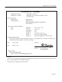
Declaration of Conformity
Manufacturer’s Name :
Manufacturer’s Address
Declare the Product
Product Name
Model Number(s)
Conform to the following Standards
LVD
EMC
: Japan CBM Corporation
: CBM Bldg.,5-68-10, Nakano, Nakano-ku, Tokyo
164-0001, Japan
Thermal Printer
CBM-230 Series
(CBM230R,CBM230P,CBM231R,CBM231P)
(S.No.95Y0001 ~
)
: EN60950:
: EN55022:
: EN61000-3-2:
: EN50082-1:
: IEC801-2:
: IEC801-3:
: IEC801-4:
1992+A1+A2 : 1993
1994 Class A
1995
1992
1991 4KV CD, 8KV AD
1984 3V/m, 27MHz-500Mhz
1988 0.5KV Signal Line, 1KV AC mains
Supplementary Information
“The product complies with the requirements of the Low Voltage Directive 73/23/EEC, 93/68/EEC and
the EMC Directive 89/336EEC, 92/31/EEC, 93/68EEC”
Place
Tokyo, Japan
Date
March, 1998
Signature
Full Name: Mikio Moriya
Position:
General Manager
R & D Department
Europe Contact :
Norco Declaration AB
Box 7146 S-250 07 Helsingborg Sweden
Warning :
This is a Class A products. In a domestic environment this product may cause radio interference in which case
the user may be required to take adequate measures.
This declaration is applied only for 230V model.
CITIZEN
CBM-230/231 User’s Manual
IMPORTANT SAFETY INSTRUCTIONS
•
•
•
•
•
•
•
•
•
•
•
•
Read all of these instructions and save them for future reference.
Follow all warnings and instructions marked on the product.
Unplug this product from the wall outlet before cleaning. Do not use liquid or aerosol cleaners. Use a damp
cloth for cleaning.
Do not use this product near water.
Do not place this product on an unstable cart, stand or table. The product may fall, causing serious damage
to the product.
Slots and openings on the back or bottom of the case are provided for ventilation. To ensure reliable
operation of the product and to protect it from overheating, do not block or cover these openings. The
openings should never be blocked by placing the product on a bed, sofa, rug of other similar surface. This
product should never be placed near or over a radiator or heater. This product should not be placed in an
built-in installation unless proper ventilation is provided.
This product should be operated from the type of power source indicated on the marking label. If you re
not sure of the type of power available, consult your dealer or local power company.
Do not allow anything to rest on the power cord. Do not place this product where the cord will be walked on.
If an extension cord is used with this product, make sure that the total of the ampere ratings of the products
plugged into the extension cord does not exceed the extension cord ampere rating. Also, make sure that the
total of all products plugged into the wall outlet does not exceed 15 amperes.
Never push objects of any kind into this product through cabinet slots as they may touch dangerous voltage
points or short out parts that could result in a risk of fire or electric shock. Never spill liquid of any kind on
the product.
Except as explained elsewhere in this manual, do not attempt to service this product by yourself. Opening
and removing the covers that are marked “Do Not Remove” may expose you to dangerous voltage points or
other risks. Refer all servicing on those compartments to service personnel.
Unplug this product from the wall outlet and refer servicing to qualified service personnel under the
following conditions:
A. When the power cord or plug is damaged or frayed.
B. If liquid has been spilled into the product.
C. If the product has been exposed to rain or water.
D. If the product does not operate normally when the operating instructions are followed. Adjust only
those controls that are covered be the operating instructions since improper adjustment of other controls
may result in damage and will often require extensive work by a qualified technician to restore the
product to normal operation.
E. If the product has been dropped or the cabinet has been damaged.
F. If the product exhibits a distinct change in performance, indicating a need for service.
IMPORTANT: This equipment generates, uses, and can radiate radio frequency energy and if not installed
and used in accordance with the instruction manual, may cause interference to radio communications. It has
been tested and found to comply with the limits for a Class A computing device pursuant to Subpart J of Part 15
off FCC Rules, which are designed to provide reasonable protection against such interference when operated in a
commercial environment. Operation of this equipment in a residential area is likely to cause interference, in
which case the user at his own expense will be required to take whatever measures may be necessary to correct
the interference.
CAUTION: Use shielded cable for this equipment.
Sicherheitshinweis
Die Steckdose zum Anschluß dieses Druckers muß nahe dem Grät angebracht und leicht zugänglich sein.
For Uses in Canada
This digital apparatus does not exceed the class A limits for radio noise emissions from digital, apparatus, as set
out in the radio interference regulations of the Canadian department of communications.
Pour L’utilisateurs Canadiens
Cet appareil numérique ne dépasse pas les limites de carégorie a pour les émissions de bruit radio émanant
d’appareils numériques, tel que prévu dans les réglements sur l’interférence radio du départment Canadien des
communications.
CITIZEN
CBM-230/231 User’s Manual
CONTENTS
1.
GENERAL DESCRIPTION ...............................................................................................................................1
1.1
Features............................................................................................................................................ 1
1.2
Precautions for Installation ............................................................................................................... 1
2.
BASIC SPECIFICATIONS.................................................................................................................................2
2.1
Model Classification......................................................................................................................... 2
2.2
Specifications List ............................................................................................................................ 2
2.2
Specifications List ............................................................................................................................ 3
2.3
Specifications for Printing Paper....................................................................................................... 4
2.3.1
Specified Paper ......................................................................................................................... 4
2.3.2
Printing Position ....................................................................................................................... 4
2.3.3
Head and Cutter Positional Relations ........................................................................................ 4
3.
APPEARANCE AND COMPONENT PARTS .................................................................................................5
4.
OPERATION........................................................................................................................................................6
4.1
Connecting the Interface Cable ......................................................................................................... 6
4.2
Connecting the Drawer Kick Connector ............................................................................................ 6
4.2
Connecting the Drawer Kick Connector ............................................................................................ 7
4.3
Inserting the Paper Roll .................................................................................................................... 8
4.4
Operation Panel .............................................................................................................................. 12
4.5
Opening the Auto Cutter(CBM-231) ............................................................................................... 13
5.
SETTING OF DIP SWITCHES .......................................................................................................................14
6.
PARALLEL INTERFACE................................................................................................................................16
6.1
Specifications ................................................................................................................................. 16
6.2
Connector's Pin Configuration ........................................................................................................ 16
6.3
Input / Output Signals ..................................................................................................................... 17
7.
6.3.1
Input / Output Signals ............................................................................................................. 17
6.3.2
Electrical Characteristics......................................................................................................... 18
6.3.3
Timing Chart .......................................................................................................................... 19
6.3.4
Data Receiving Control ........................................................................................................... 19
6.3.5
Buffering ................................................................................................................................ 19
SERIAL INTERFACE ......................................................................................................................................20
7.1
Specifications ................................................................................................................................. 20
7.2
Connector's Pin Configuration ........................................................................................................ 21
7.3
Input / Output Signals ..................................................................................................................... 22
7.3.1
Input / Output Signals ............................................................................................................. 22
7.3.2
Data Configuration.................................................................................................................. 23
7.3.3
Error Detection ....................................................................................................................... 23
7.3.4
Data Receiving Control ........................................................................................................... 24
CITIZEN
CBM-230/231 User’s Manual
7.3.5
Buffering ................................................................................................................................ 24
7.3.6
Electrical Characteristics......................................................................................................... 25
8.
DRAWER KICK CONNECTOR .....................................................................................................................26
8.1
Specifications.................................................................................................................................. 26
8.2
Connector's Pin Configuration......................................................................................................... 26
8.3
Drive Circuit................................................................................................................................... 26
9.
PRINT CONTROL FUNCTION ......................................................................................................................27
9.1
Control Codes List .......................................................................................................................... 27
9.2
Input Data Format........................................................................................................................... 28
10.
Character Code Table ...................................................................................................................................52
10.1 International ................................................................................................................................... 52
10.2 International Character Code Table................................................................................................. 53
Appendix 1. PRECAUTIONS AND MAINTENANCE ..........................................................................................54
Appendix 2. External Dimensions .............................................................................................................................56
Appendix 3. Block Diagram.......................................................................................................................................58
CITIZEN
CBM-230/231 User’s Manual
1.
GENERAL DESCRIPTION
This is a small line thermal printer developed to be used for various data communication terminals such as POS
terminals and kitchen printers.
POS terminals, kitchen printers, and so on.
be widely used for various types of applications.
With its abundant features, it can
Read this manual thoroughly prior to using the printer to
understand its contents.
1.1
Features
1. Compact, light-weight, and small installation area required
2. High speed and low noise due to line th ermal printing
3. High reliability due to long-life printing head and simple mechanism
4. Input buffer incorporated
5. Capable of printing a bar codes (exclusive command)
6. Drawer kickout interface incorporated
7. Equipped with an auto cutter (CBM-231)
8. User-Defined character registration function (95 characters)
9. Easy handling due to incorporated power supply
1.2 Precautions for Installation
1.
Upon unpacking the printer, make sure that the following parts are contained in the package.
Printer main body.............. 1 unit
Sample paper roll .............. 1 roll
Instruction manual............. 1 copy
2. Install the printer on a flat and stable desk or table.
3. Do not install the printer near a heater or in the direct sunshine.
4. Do not use the printer in a high -temperature, high-humidity, or contaminated environment.
5. Prepare a separate AC power supply from other equipment which causes noises.
6. Connect only a specified solenoid to the drawer kick connector.
7. When transporting or not using the printer for a long period of time, leave the printing head kept up.
1
CITIZEN
CBM-230/231 User’s Manual
2.
BASIC SPECIFICATIONS
2.1
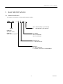
Model Classification
The model is classified by the following designation method.
CBM – 230
–
R
F
120
*
Non : Standard Spec. (48 columns)
E : Special Spec. (42 columns)
Model
CBM-230 :
Standard model
CBM-231 :
Auto cutter incorporated
AC Adapter
120 : For AC120V
230 : For AC230V
Character set
F : Internasional use
Interface
R : Serial, RS-232C
P : Parallel, Conforms to CENTRONICS
2
CITIZEN
CBM-230/231 User’s Manual
2.2
Specifications List
Item
Printing method
Printing width
Dot density
Printing speed
Number of columns
Character dimensions
Character types
Bar code types
Line pitch
Printing paper
Interface
Input buffer
Supply voltage
Power consumption
Weight
Outer Dimensions
Operating temperature
Storage temperature
Reliability
Description
Line thermal dot printing system
72 mm/576 dots *(63 mm/504 dots)
8 dots/mm (horizontal, vertical)
62.5 mm/sec. (at max. speed) (500 dot Line/sec.)
48 columns *(42 columns): (12 × 24, Font A)
64 columns *(56 columns) : ( 9 × 17, Font B)
1.25 mm × 3.00 mm (12 × 24, Font A)
0.88 mm × 2.13 mm ( 9 × 17, Font B)
Alphanumeric, International characters
UPC-A/E, JAN(EAN) 13 columns/8 columns, ITF
CODE 39, CODE 128, CODABAR
4.23mm (1/6 inch.), Can be selected by a command
(min. 1/203 inch)
Thermal paper roll, 80 mm × φ83 mm
(Refer to Specifications for Printing Paper)
Serial (RS-232C), Parallel (Conforms to CENTRONICS)
72 bytes / 4 KB (Can be selected with the DIP switch)
120 V AC ± 10 %, 60 Hz
230 V AC ± 10 %, 50 or 60 Hz
100W
1.70 kg (CBM-230), 1.85 kg (CBM-231)
145 (W) × 216 (D) × 150 (H)
5 to 40°C
–20 to 60°C
Print head’s life : Pulse resistance … 50 million pulses
(printing rate 12.5%)
Wear resistance … 30 km (at normal temperature and
humidity, with specified recommended paper)
Auto cutter’s life : 300,000 cuts
* 42 columns spec.(Special ROM only)
3
CITIZEN
CBM-230/231 User’s Manual
2.3
Specifications for Printing Paper
2.3.1 Specified Paper
Type
: Thermal paper
Paper width
: 80 + 0 or –1 mm
Paper thickness
: 65 ± 5µm
Roll diameter
: φ83 mm or less
Print surface
: Outside of the roll (surface)
Recommended paper
: TF50KS-E2C made by Nihon Seishi or other equivalent
Core
: φ12 (inner diameter), φ18 (outer diameter)
[Caution]
Do not paste the paper to the core.
2.3.2 Printing Position
2.3.3 Head and Cutter Positional Relations
4
CITIZEN
CBM-230/231 User’s Manual
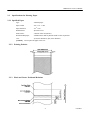
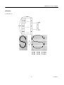
3.
APPEARANCE AND COMPONENT PARTS
5
CITIZEN
CBM-230/231 User’s Manual
4.
OPERATION
4.1
Connecting the Interface Cable
1. Turn off the power.
2. Confirm the vertical direction of a cable terminal and connect it to the interface connector.
3. Fix the cable terminal.
Serial interface
: Tighten screws to fix.
Parallel interface
: Turn a fixture in an arrow direction to fix.
4. Connect the cable to the computer.
6
CITIZEN
CBM-230/231 User’s Manual
4.2
Connecting the Drawer Kick Connector
1. Turn off the power.
2. Confirm the vertical direction of a drawer kick cable connector and insert it into the drawer kick
connector on the back of the printer.
3. Using a screw, fix a drawer's earthing conductor to the earth terminal of the printer.
[Caution]
Connect only a specified drawer(solenoid) to the drawer kick connector.
7
CITIZEN
CBM-230/231 User’s Manual
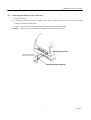
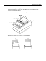
4.3 Inserting the Paper Roll
[Caution]
Be sure to use a specified paper roll.
1. Open the printer cover.
2. Shift the head-up lever in an arrow direction to move up the printing head.
[Caution]
When setting the paper roll, you do not have to open the auto cutter. (CBM-231)
CBM-231
8
CITIZEN
CBM-230/231 User’s Manual
3. Using the scissors, cut the end of the paper at a right angle.
[Caution]
Do not insert the paper with its end fluffed or bent.
4. Confirm the winding direction of the paper roll. Opening the paper holder in the direction of the arrow,
set the paper and hold the core center properly.
[Caution]
Make sure that the paper roll rotates smoothly without tilting the paper.
9
CITIZEN
CBM-230/231 User’s Manual
5. Insert the end of the paper into the paper inlet, turn the paper feed knob in the direction of the arrow to
feed out the paper about 5 cm from the paper outlet of the auto cutter or nose of the manual cutter.
(The figure below shows the CBM-231).
[Caution]
Do not turn the paper feed knob when the printing head is in its down position.
6. When the paper is tilting, correct it and move the printing head down.
10
CITIZEN
CBM-230/231 User’s Manual
7. Cut off the surplus paper at the edge of the paper outlet of the auto cutter or blade of the manual cut ter.
8. Close the printer cover. You are finished with setting of the paper roll.
[Caution]
Do not open the printer cover during printing.
9. When removing the remaining paper upon its replacement with new one, pull it out straight with the
printing head kept up.
10. When using the auto loading function, follow the procedure below.
(1) Change the setting of the DIP switch to the auto loading mode. (Turn on DS1 -3)
(2) Move the printing head up.
(3) Insert the end of the paper straight into the paper inlet of the printer and move down the printing
head. The paper is automatically pulled in by a constant amount.
(4) Close the printer cover to finish setting of the paper roll.
[Caution]
When the paper is tilting, move up the printing head and correct it manually.
11
CITIZEN
CBM-230/231 User’s Manual
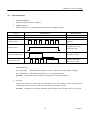
4.4
Operation Panel
1. POWER LED(green)
Illuminated when the power is supplied.
2. ERROR LED(red)
Indicates different errors, depending on the illuminated or blinking condition.
Eroor
Printer cover open
Head Up
Display pattern
Illuminated
Illuminated
Resetting Method
Close the cover
Move down the head
Memory check
Disabled
Head overheat
Automatically reset by
temperature drop
Macro execution wait
Press the LF switch
Cutter motor lock
Eliminate paper jam
and press LF switch
3. PAPER LED(red)
Near end enabled
: Illuminated when the paper is near its end (Stops after printing the set length)
Near end disabled
: Illuminated when the paper is at its end (Stops printing)
[Caution]
Use the DIP switch to enable or disable the near end detecting function.
4. LF switch
Pressing this switch for a short time feeds the paper by one line. Holding it down feeds the paper
continuously. In case of macro execution wait, pressing the LF switch executes it.
[Caution]
Depending on a selection of the DIP switch, the paper can be fed when the cover is opened.
12
CITIZEN
CBM-230/231 User’s Manual
5. LF switch and power switch
Self-printing is performed by turning on the power switch with the LF switch held down.
4.5
Opening the Auto Cutter(CBM-231)
When the paper is jamming or when you open the auto cutter in order to clean the head, raise the auto cutter,
pulling the cutter lock lever in the direction of the arrow.
[Caution]
Immediately after printing, the printing head and motor have a high temperature.
Never touch the printing head and motor when you open the auto cutter.
13
CITIZEN
CBM-230/231 User’s Manual
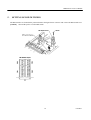
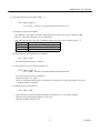
5.
SETTING OF DIP SWITCHES
The DIP switches are located in the position shown in the figure below. Unscrew and remove the DIP switch cover.
[Caution]
Turn off the power to set the DIP switch.
14
CITIZEN
CBM-230/231 User’s Manual
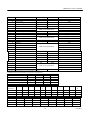
DS1-1
DS1-2
DS1-3
DS1-4
DS1-5
DS1-6
DS1-7
DS1-8
Paper cutter
Cover open
Auto loading
Input buffer
Paper near end
Paper near end remainder 1
Paper near end remainder 2
CR switching
DS2-1
DS2-2
DS2-3
DS2-4
DS2-5
DS2-6
DS2-7
DS2-8
Print density
Print density
International character
Unused
International character
International character
International character
International character
DS3-1
DS3-2
DS3-3
DS3-4
Bit length
Parity
Odd / even
DTR / XON-XOFF
DS4-1
DS4-2
DS4-3
DS4-4
Baud rate
Baud rate
Baud rate
Unused
ON
Provided
Disabled
Enabled
72 bytes
Disabled
Setting upon Shipment
*
OFF
OFF
OFF
OFF
OFF
OFF
OFF
OFF
Unprovided
Enabled
Disabled
4K bytes
Enabled
Refer to the table below
LF activated
Ignored
ON
OFF
Setting upon Shipment
ON
OFF
OFF
OFF
OFF
OFF
OFF
OFF
Refer to the table below
International
Refer to the table below
ON
7 bits
Provided
Even
XON-XOFF
Unprovided
Odd
DTR / DSR
ON
OFF
Setting upon Shipment
OFF
OFF
OFF
OFF
OFF
Setting upon Shipment
OFF
ON
ON
OFF
Refer to the table below
The switch segment marked * are set depending on types.
The DIP switches DS3 and DS4 are only for the serial interface.
Remaining printable Length
DS1-6
DS1-7
Print density
DS2-1
DS2-2
International U.S.A.
Character
DS2-5
OFF
DS2-6
OFF
DS2-7
OFF
DS2-8
OFF
Baud Rate
DS4-1
DS4-2
DS4-3
150
OFF
OFF
OFF
0 cm
OFF
OFF
50 cm
ON
OFF
1m
OFF
ON
2m
ON
ON
Light
OFF
OFF
Standard
ON
OFF
Dark
OFF
ON
Darker
ON
ON
France Germany
ON
OFF
OFF
OFF
OFF
ON
OFF
OFF
300
ON
OFF
OFF
U.K.
ON
ON
OFF
OFF
600
OFF
ON
OFF
Denmark Sweden
I
OFF
ON
OFF
OFF
ON
ON
OFF
OFF
1200
ON
ON
OFF
15
Italy
Spain
Japan
OFF
ON
ON
OFF
ON
ON
ON
OFF
OFF
OFF
OFF
ON
2400
OFF
OFF
ON
4800
ON
OFF
ON
Norway Denmark
II
OFF
OFF
OFF
ON
ON
OFF
ON
ON
9600
OFF
ON
ON
19200
ON
ON
ON
CITIZEN
CBM-230/231 User’s Manual
6.
PARALLEL INTERFACE
6.1
Specifications
Data input method
: 8-bit parallel(DATA 1-8)
Control signal
: ACK, BUSY, STB, FAULT, PE, RESET
Applicable connectors
: Printer side
: 57LE-40360(equivalent to amphenol)
Cable side
: 57-30360(equivalent to amphenol)
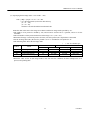
6.2 Connector's Pin Configuration
No.
1
2
3
4
5
6
7
8
9
10
11
12
13
14
15
16
17
18
Signal Name
STB
DATA 1
DATA 2
DATA 3
DATA 4
DATA 5
DATA 6
DATA 7
DATA 8
ACK
BUSY
PE
+5V DC
GND
FRAME GND
No.
19
20
21
22
23
24
25
26
27
28
29
30
31
32
33
34
35
36
Signal Name
TWISTED PAIR GND
TWISTED PAIR GND
TWISTED PAIR GND
TWISTED PAIR GND
TWISTED PAIR GND
TWISTED PAIR GND
TWISTED PAIR GND
TWISTED PAIR GND
TWISTED PAIR GND
TWISTED PAIR GND
TWISTED PAIR GND
TWISTED PAIR GND
RESET
FAULT
GND
DRAWER SWITCH OUTPUT
+5V DC
16
CITIZEN
CBM-230/231 User’s Manual
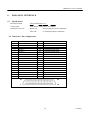
6.3
Input / Output Signals
6.3.1 Input / Output Signals
(1) Input signals to the printer
• DATA
: This is an 8-bit parallel signal (Positive logic)
• STB
: This is a strobe signal to read in 8-bit data (Negative logic)
• RESET
: This signal resets the entire printer (Negative logic) 1 ms or more
(2) Output signals from the printer
• ACK
: This is an 8-bit data request signal. Pulse signal output at the end of the BUSY signal
(Negative logic)
• BUSY
: This signal indicates the BUSY state of the printer. Enter new data when it is at LOW.
(Positive logic)
• FAULT
: This signal is set to low when the printer has an alarm. When this is done, all control
circuits in the printer stop.(Negative logic)
• PE
: This signal is output when the printing paper has run out or is running out.
(Positive logic)
• Drawer switch output
: This signal is set to HIGH when the switch is opened, and to LOW when shorted.
(3) Power signals
• +5VDC
: This is a 5 V output pulled up at a 3.3 k Ω resistor.
• GND
: This is a common ground on the circuits.
17
CITIZEN
CBM-230/231 User’s Manual
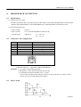
6.3.2 Electrical Characteristics
(1) Input signal level
All input signals are at the TTL level.
"HIGH" level: 2.0 V at minimum
"LOW" level : 0.8 V at maximum
(2) Output signal level
All output signals are at the TTL level.
"HIGH" level: 2.4 V at minimum
"LOW" level : 0.4 V at maximum
(3) Input/output conditions
All input signals are pulled up at 3.3 kΩ.
All output signals are pulled up at 3.3 kΩ.
18
CITIZEN
CBM-230/231 User’s Manual
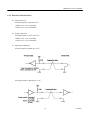
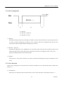
6.3.3 Timing Chart
(1) Data input and printing timing
T1, T2, T3
0.5 MIN
T4
270 ns MAX
T5
TYP
T6
500 ms MIN (at power on)
6.3.4 Data Receiving Control
When the BUSY signal is at LOW, the data from the host side can be received, but when at HIGH, it cannot be
received.
6.3.5 Buffering
A size of the input buffer can be selected by setting the DIP switch segment DS1-4. When a 4KB buffer is
selected, the host side is immediately free because a large amount of data can be buffered.
19
CITIZEN
CBM-230/231 User’s Manual
7.
SERIAL INTERFACE
7.1
Specifications
(1) Synchronizing system : Asynchronous
(2) Baud rate
150, 300, 600, 1,200, 2,400, 4,800, 9,600, 19,200 bps (Selected by the user)
(3) Word length
Start bit
: 1 bit
Data bit
: 7 bits or 8 bits (Selected by the user)
Parity bit
: Odd/even parity or no parity (Selected by the user)
Stop bit
: 1 bit or more
(4) Signal polarity
RS-232C
• Mark
= Logic "1" (–3 V to –12 V)
• Space
= Logic "0" (+3 V to +12 V)
(5) Receive data (RD signal)
RS-232C
• Mark
=1
• Space
=0
(6) Data receiving control (DTR signal)
RS-232C
• Mark
: Data transfer not possible
• Space
: Data transfer possible
(7) Data transmission control (TD signal)
DC1 code(11H) X-ON
: Data reception possible
DC3 code(13H) X-OFF
: Data reception not possible
20
CITIZEN
CBM-230/231 User’s Manual
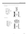
7.2
Connector's Pin Configuration
No.
1
7
3
20
2
6
[Cautions]
Signal Name
FG
GND
RD
DTR
TD
DSR
Input/Output
Function
Frame Grand
Signal GND
Receiving data
Printer BUSY signal
Transmission data
Data set ready
Input
Output
Output
Input
1. RS-232C signals are based on the EIA RS-232C.
2. When no data is being transferred, the receive data should be always maintained in the mark state.
Applicable connectors (D-Sub connectors)
Printer side : 17LE-13250 (Equivalent to DDK)
Cable side
: 17JE-23250 (Equivalent to DDK)
21
CITIZEN
CBM-230/231 User’s Manual
7.3
Input / Output Signals
7.3.1 Input / Output Signals
(1) RD
This is a serial receive data signal. When there is a framing error, overrun error, or parity error, that data
is printed as "?."
(2) DTR
Write the data or a command when this signal is ready. If you write while it is busy, the data will be
ignored, resulting in an overrun error. The data can be written into the input buffer even during printing.
A BUSY signal is also issued at power-on, during test printing, in the on-line mode, or upon occurrence
of reset.
(3) TD
When the remaining capacity of the input buffer on the printer side comes to 10 bytes(at 72 bytes) or 128
bytes(at 4K bytes) while receiving the data, DC3(13H), a data reception impossible signal, is output.
When the remaining capacity of the input buffer comes to over 20 bytes(at 72 bytes) or 256 bytes(at 4K
bytes)DC1(11H), a data reception possible signal is output to the host side.
When transmitting the status information, if DTR/DSR control has been selected, the data will be
transmitted after confirming that DSR is a space.
If DTR/DSR control has not been selected, the data will be transmitted, ignoring DSR.
(4) FG
This is a Frame ground.
(5) GND
This is a common ground on the circuits.
22
CITIZEN
CBM-230/231 User’s Manual
7.3.2 Data Configuration
(1)
(2)
(3)
(1) Start bit
(2) Data bit(+ parity bit)
(3) Stop bit(1 or more)
(1) Start bit
When half a bit has passed since a fall edge of a mark to a space, the state of the bit is read in again, and if it
is a space, it will be recognized as a start bit. If it is a mark, it will not be recognized as the start bit. The
start bit will be detected again without assuming it to be an error.
(2) Data bit + parity bit
The data bit and parity bit are sampled for one bit worth of time since the time of half the start bit and
assume the then state to be the data for the relevant bits. The bits are arranged in order of bit 0, bit 1, ....,
parity bit, starting from the one next to the start bit.
(3) Stop bit
The stop bit is a 1-bit or more mark level. If a space is detected in detecting the stop bit, a framing error will
result.
7.3.3 Error Detection
A parity error, framing error, and overrun error are detected. When an error is detected, that data is stored in the
buffer as "?."
(1) Framing error
When a space is detected at stop bit detection time, an error result. That data is stored in the buffer as "?."
23
CITIZEN
CBM-230/231 User’s Manual
(2) Parity error
When a parity check has been specified and an error is detected at parity check time, that data is stored in the
buffer as "?."
(3) Overrun error
When an overrun error is detected, that data is stored in the buffer as "?."
7.3.4 Data Receiving Control
When DTR/DSR control has been selected, if the DTR signal is at SPACE, the data from the host side can be
received, but when at MARK, it cannot be received. When DTR/DSR control has not been selected, the data
from the host side can be received after transmitting XON, but it cannot be received after transmitting XOFF.
7.3.5 Buffering
There are DTR and TD signals as control signals for data transfer to the input buffer.
(1) DTR signal (Refer to 7.3 1)
(2) TD signal (Refer to 7.3 1)
24
CITIZEN
CBM-230/231 User’s Manual
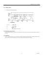
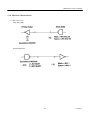
7.3.6 Electrical Characteristics
(1) RS-232C circuit
Input (RD, DSR)
Output (DTR, TD)
25
CITIZEN
CBM-230/231 User’s Manual
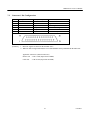
8.
DRAWER KICK CONNECTOR
8.1
Specifications
(1) Drawer kick drive signal
The pulses specified by ESC p are output. The state of the switch(+) can be known through the pin 34 of the interface
connector when parallel interface is used, and through the ESC u command when the serial interface is used.
(2) Electrical characteristics
1) Drive voltage
: DC 24 V
2) Drive current
: 0.8 A at maximum(should be within 510 ms)
3) Switch signal
: Signal level
"L" = 0 to 0.5 V
"H" = 3 to 5 V
8.2
Connector's Pin Configuration
No.
1
2
3
4
5
6
Signal Name
FG
DRAWER 1
DRSW
VDR
DRAWER 2
GND
Connector used
Applicable connector
Function
Frame ground
Drawer 1 drive signal
Drawer switch input
Drawer driving power
Drawer 2 drive signal
Common ground on the circuits
: TM5RJ3-66(HIROSE)
: Equivalent to TM3P-66P(HIROSE)
[Cautions] 1) No output is allowed during printing.
2) The drawers 1 and 2 cannot be driven at the same time.
3) A solenoid for the drawer should be of 36Ω or more.
(See to it that an output current will not exceed 0.8 A. Be careful not to use a drawer with a
current over 0.8A to avoid damage to the printer.)
8.3
Drive Circuit
26
CITIZEN
CBM-230/231 User’s Manual
9.
PRINT CONTROL FUNCTION
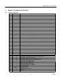
9.1
Control Codes List
Character
1
2
3
4
5
6
7
8
9
10
11
12
13
14
15
16
17
18
19
20
21
22
23
24
25
26
27
28
29
30
31
32
33
34
35
36
37
38
39
40
41
42
HT
CR
LF
ESC SP
!
%
&
*
–
2
3
@
D
E
G
J
R
c3
c4
c5
d
p
t
v
u
{
V
$
¥
GS k
w
h
H
f
*
/
:
^
ESC =
a
i
m
Command/Description
Horizontal tab command
Print command
Printing and paper feed
Setting the right space amount of the character
Specifying collective the print mode
Specifying/canceling the download character set
Defining the download characters
Specifying the bit image mode
Specifying/canceling the underline
Specifying the 1/6-inch line feed rate
Setting the line feed rate n/360 inch
Initializing the printer
Setting the horizontal tab position
Specifying/canceling highlighting
Specifying/canceling double printing
Printing and feeds the paper n/360 inch
Selecting the international characters
Selecting the paper near end sensor effective for outputting the paper end signal
Selecting the paper near end sensor effective for stopping printing
Enabling/disabling the panel switches
Printing and feeding the paper by n-lines
Generating the specified pulses
Selecting the character codes table
Transmitting the printer status
Transmitting the status of the peripheral device
Specifying/canceling the inverted characters
Specifying/canceling the 90°- right-turned characters
Specifying the absolute position
Specifying the relative position
Printing the bar code
Selecting the horizontal size (scale factor) of the bar code
Selecting the height of the bar code
Selecting the printing position of the HRI characters
Selecting the font of HRI character
Defining the download bit image
Printing the download bit image
Starting/ending the macro definition
Executing the macro
Data input control
Aligning the the characters
Full cut
Partial cut
27
CITIZEN
CBM-230/231 User’s Manual
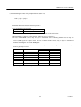
9.2
Input Data Format
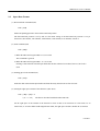
(1) Horizontal Tab Command (HT)
Code : [09]h
Mones the printing position to the next horizontal tab position
The horizontal tab position is set by ESC D. The initial setting of the horizontal tab position is every 8
characters (9th columns, 17th columns, 25th columns, 33rd columns, 41st columns) of Font A.
(2) Print command (CR)
Code : [0D]h
1) When the DIP switch segment DS1-8 is set to OFF
This command is ignored.
2) When the DIP switch segment DS 1- 8 is set to ON
Printing is done when the internal input buffer has the data. When it has no data, however, line feed is
done.
(3) Printing paper feed command (LF)
Code : [0A]h
Prints the data in the internal input buffer and feeds the line(s) based on the set line feed rate.
(4) Setting the right space amount of the characters (ESC SP n)
Code : [1B]h + [20]h + n
* {0 ≤ n ≤ 20}
The data is described with the hexadecimal code.
Set the right space of the amount of the character in term of dots (in an increment of 1/203 inch). As an
initial value, n=0. In the double width magnification mode, the right space amount is double the set amount.
28
CITIZEN
CBM-230/231 User’s Manual
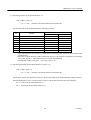
(5) Specifying collectively the print mode (ESC ! n)
Code : [1Bh] + [21h] + n
* {0 ≤ n ≤ FF}
The data is described with the hexadecimal code.
Specifies the print mode. Each bit of n has the following meaning.
Bit
0
1
2
3
4
5
6
7
Value
Function
Character font
Undefined
Undefined
Highlighting
Vertical double magnification
Horizontal double magnification
Undefined
Underline
0
Font A
1
Font B
Cancel
Cancel
Cancel
Specify
Specify
Specify
Cancel
Specify
• Four-fold characters are formed by simultaneously specifying both vertical and horizontal double
magnifications.
• The entire printed character width is underlined. However, the characters skipped by the horizontal
tab are not. The 90°C –right-turned characters are also not underlined.
• An underline width is set by ESC –. The initial value is "0. "
(6) Specifying/canceling the download character set (ESC % n)
Code : [1B]h + [25]h + n
* {0 ≤ n ≤ FF}
The data is described with the hexadecimal code.
Specifying or cancels the download characters. The download characters and download bit images cannot be
defined simultaneously. For n, lowest bit (n0) is effective. The lowest bit has the following meanings.
n0 = 0 : Cancels the download character set
n0 = 1 : Specifying the download character set
29
CITIZEN
CBM-230/231 User’s Manual
(7) Defining the download characters (ESC & s n m a {D1 D2 ~ Dn})
Code : [1B]h + [26]h + s + n + m +a + Dn
* {s = 03}
{20 ≤ n ≤ 7E}
{20 ≤ m ≤ 7E}
{For the Font A; 0 ≤ a ≤ 0C, For the Font B; 0 ≤ a ≤ 09}
The data is described with the hexadecimal code.
Defines the font for the download characters of alphanumeric characters.
• "s" denotes the number of bytes in the vertical direction.
• "n" denotes a start character code, and m denotes an end character code. When defining only one character,
n should be equal to m (n = m).
• Definable character codes are ASCII codes, totally 95 characters ranging from <20>H to <7E>H.
• "a" denotes the numberof dots in the horizontal direction to be derection to be defined.
• "Dn" is the data to be defined and denotes a pattern corresponding to "a" dot in the horizontal direction
from the left end. The right remaining pattern is filled with space.
• Once the download characters are defined, they remain effective until redefinition, execution of ESC @,
execution of GS *, or power -off.
30
CITIZEN
CBM-230/231 User’s Manual
[Example]
For the Font A
31
CITIZEN
CBM-230/231 User’s Manual
For the Font B
32
CITIZEN
CBM-230/231 User’s Manual
(8) Specifying the bit Image (ESC * m n1 n2 D1 ~ Dn)
Code : [1B]h + [2A]h + m + n1 + n2 + Dn
* {m= Bit image mode (refer to the table below)}
{0 ≤ n1 ≤ FF}
{0 ≤ n2 ≤ 02}
The data is described with the hexadecimal code.
Prints the data in the form of bit image in accodance with the bit image mode specified by "m".
• The number of bit printed is divided by 256, and n2 and is assumed to be a quotient, and n1 to be the
remainder.
• The total number of dots printed in the form of bit image is n1 + (256 × n2).
• When the bit image is entered beyond a 1 dot line (576 dots) position, the surplus data is discarded.
• For the bit image data (Dn), the bit to be printed is set to "1" and that not to be printed to "0".
• The following table shows the bit image mode.
( ) = For 42 columns spec.
Vertical
Horizontal
m(Hex)
Mode
No.of Dots
Dot Density
Dot Density Max. No. of Dots
0
8-dot single density
8
67 DPI
101 DPI
288 (252)
1
8-dot double density
8
67 DPI
203 DPI
576 (504)
20
24-dot single density
24
203 DPI
101 DPI
288 (252)
21
24-dot double density
24
203 DPI
203 DPI
576 (504)
• When the value set for "m (bit image mode)" dose not meet the condition, the data subsequent to n1 is
processed as printing data.
33
CITIZEN
CBM-230/231 User’s Manual
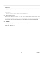
The following shows the relations between the bit image data and printed dots.
• 8-dot Bit Image
• 24-dot Bit Image
34
CITIZEN
CBM-230/231 User’s Manual
(9) Specifying/canceling the underline (ESC – n)
Code: [1B]h + [2D]h + n
* {0 ≤ n ≤ 02} The data is described with the hexadecimal code.
Specifying or cancels the underline.
• An underline is provided for the entire printed character width except a portion skipped by HT.
• The 90°- right-turned characters are not underlined.
• The following table lists the types of underlines deponing on the values an initial value is "1".
n (Hex)
0
1
2
Type
Cancels an underline
Specifies a 1-dot width underline
Specifies a 2-dot-wide underline
(10) Specifying the 1/6 inch line feed rate (ESC 2)
Code : [1B]h + [32]h
Sets a line feed rate per line to 1/6 inch.
(11) Setting the line feed rate n/360 inch (ESC 3 n)
Code : [1B]h + [33]h + n
* {0 ≤ n ≤ FF} The data is described with the hexadecimal code.
Sets a line feed rate per line to n/360 inch.
• The initial value is n = [3C]h
• Since an actual mechanical pitch is 1/203 inch, it is internally converted approximate to the value
specified with this command.
(12) Initializing the printer (ESC @)
Code : [1B]h + [40]h
Clears the data stored in the internal print buffer and initializes various settings (default).
• The data in the internal input buffer is not cleared.
• Reads in the DIP switches again.
35
CITIZEN
CBM-230/231 User’s Manual
(13) Setting the horizontal tab position (ESC D n NUL)
Code : [1B]h + [44]h + n [00]h
* {0 ≤ n ≤ FF} The data is described with the hexadecimal code.
Sets the horizontal tab position.
• "n" denotes the number of columns from the beginning to the horizontal tab position. At this time, "n" is
the setting position minus 1.
• The tab position is set in the position of the character width × n from the beginning of the line. The
character width at this time includes the right space amount of the character and is doubled when double
width magnification is specified.
• Up to 32 tab positions can be set. Setting of the tab positions beyond this limit is ignored.
• ESC D NUL clears all of set tab positions. After clraring, HT is ignored
(14) Setting the horizontal tab position (ESC D n NUL)
Code : [1B]h + [44]h + n [00]h
* {0 ≤ n ≤ FF} The data is described with the hexadecimal code.
Sets the horizontal tab position.
• Only the lowest bit(n0) is effective for "n".
• The following table lists the controls by the lowest bit (n0).
n0
Type
0
Canceling highlighting.
1
Specifying highlighting.
• Effective for all characters.
• A highlighted character has one dot each added in the horiz ontal direction.
36
CITIZEN
CBM-230/231 User’s Manual
(15) Specifying/canceling double printing (ESC G n)|
Code : [1B]h + [47]h + n
* {0 ≤ n ≤ FF} The data is described with the hexadecimal code.
Specifying/canceling the double printing.
• Only the lowest bit (n0) is effective for "n".
• The following table list the controls by "n".
n0
Type
0
Cancels double printing.
1
Specifies double printing.
• The printing results of double printing and highlighted printing are exactly the same.
.
(16) Printing and feeding the paper n/360 inch (ESC J n)
Code : [1B]h + [4A]h + n
* {0 ≤ n ≤FF} The data is described with the hexadecimal code.
Prints the data in the print buffer and feeds the paper by n/360 inch.
• A set rate does not remain.
• The beginning of the line is assumed to be the next printing start position.
• Since an actual mechanical pitch is 1/203 inch, it is internally converted approximate to the value
specified with this command.
(17) Selecting the international characters (ESC R n)
Code : [1B]h + [52]h + n
* {0 ≤ n ≤ 0A) The data is described with the hexadecimal code.
37
CITIZEN
CBM-230/231 User’s Manual
Selecting the international characters.
• Depending on the values of "n", following c haracter sets are specified.
n (Hex)
Character Set
0
U.S.A.
1
France
2
Germany
3
U.K.
4
Denmark I
5
Sweden
6
Italy
7
Spain
8
Japan
9
Norway
A
Denmark II
• An initial value of "n" is specified by the DIP switches (DS2 -5.6.7.8)
(18) Selecting of paper near end sensor available for output of paper near end signal (ESC c 3 n)
Code : [1B]h + [63]h + [33]h + n
* {0 ≤ n ≤ FF}
The data is described with the hexadecimal code
Specifying the condition of paper near end sensor to output pape r near end signal.
• Only the lowest bit (n0) is effective for "n".
• The bit of "n" has the following meaning.
n0
Type
0
Paper near end disabled
1
Paper near end enableed
• An initial value of "n" is specified by the DIP switch (DS1 -5).
[Caution]
Parallel interface only.
38
CITIZEN
CBM-230/231 User’s Manual
(19) Setting of paper near end sensor available for print stop (ESC c 4 n)
Code : [1B]h + [63]h + [34]h + n
* {0 ≤ n ≤ FF}
The data is described with the hexadecimal code.
Specifying the condition of paper near end sensor to stop printing operation.
• Only the lowest bit (n0) is effective for "n".
• The bit of "n" has the followings meaning.
n0
Type
0
Paper near end disabled
1
Paper near end enabled
• An initial value of "n" is specified by the DIP switch (DS1 -5).
(20) Enabling/disabling the panel switch (ESC c 5 n)
Code : [1B]h + [63]h + [35]h + n
* {0 ≤ n ≤ FF}
The data is described with the hexadecimal code.
Selecting the panel switch enable or disable.
• Only the lowest bit (n0) is effective for "n".
• The bit of "n" has the followings meaning.
n0
Type
0
LF switch enabled
1
LF switch disabled
• The initial value of n is "0".
39
CITIZEN
CBM-230/231 User’s Manual
(21) Printing and feeding the paper by n-lines (ESC d n)
Code : [1B]h + [64]h + n
* {0 ≤ n ≤ FF}
The data is described with the hexadecimal code.
Prints the data in the print buffer and feeds the paper by n-lines.
• A set rate does not remain.
• The beginning of the line is assumed to be the next printing start position.
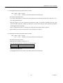
(22) Generating the specified pulses (ESC p m n1 n2)
Code : [1B]h + [70]h + m + n + n2
* {m = Connector pin number (refer to the table below)}
{0 ≤ n1 ≤ FF}
{0 ≤ n2 ≤ FF}
The data is described with the hexadecimal code.
The signals specified by n1 and n2 are output to the connector pin.
• The bit of "m" (m0) has the followings meanings.
m0
Type
0
Drawer kick pin No. 2
1
Drawer kick pin No. 5
• The ON time is n1 × 2 ms, and OFF time as n2 × 2 ms.
• When "m" is beyond a defininication range, n0 signal is output, discarding n1 and n2.
• A drawer drive duty is as follows.
ON Time
On time + OFF time
≤ 0.2
(Take OFF time should be 4 times or more longer than the ON time.)
40
CITIZEN
CBM-230/231 User’s Manual
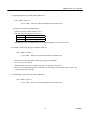
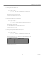
(23) Selecting Character Code Table (ESC t n)
Code : [1B]h + [74]h + n
* {0 ≤ n ≤ 1}
The data is described with the hexadecimal code.
Selecting Page n on the character code table:
• "n" has the following meanings.
n (Hex)
Type
0
IBM character No. 2
(24) Transmitting the printer status (ESC v)
Code : [1B]h + [76]h
Transmits the current printer status.
• The transmitted status is of 1 byte and its contents are as shown in the table below.
• In case of DTR/DSR control, only one byte is transmitted after confirming that the host is ready to
receive (DSR signal is in the Space mode). In case of XON/XOFF control, only one byte is transmitted
without confirming the state of the DSR signal.
• In case of DTR/DSR control, if the host is not ready to receive (DSR signal is in the Mark mode), it
waits to get ready to receive.
Bit
0
1
2
3
4
5
6
7
[Caution]
Function
Paper near end
Undefined
Paper end
Undefined
Unused
Undefined
Undefined
Undefined
Value
0
With Paper
1
Without Paper
With Paper
Without Paper
Fixed to 0
–
Serial interface only
41
CITIZEN
CBM-230/231 User’s Manual
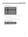
(25) Transmitting the status of the peripheral device (ESC u n)
Code : [1B]h + [75]h + n
* {n = 0}
Transmits the current status of connector pin No.3.
• "n" has the following meanings.
n (Hex)
Type
0
Drawer kick connector No. 3
• The transmitted status is of 1 byte and its contents are shown in the table below.
• When nothing is connected to the connector, The bit 0 of "n" is always "1".
• In case of DTR/DSR control, only one byte is transmitted after confirming that the host is ready to
receive (DSR signal is in Space mode). In case of XON/ XOFF control, only one byte is transmitted
without confirming the state of the DSR signal.
• In case of DTR/DSR control, if the host is not ready to receive (DSR signal is in the Mark mode), it
waits to get ready to receive.
Bit
0
1
2
3
4
5
6
7
[Caution]
Value
Function
No. 3 pin's level
Undefined
Undefined
Undefined
Unused
Undefined
Undefined
Undefined
0
“L”
Fixed to 0
1
“H”
–
Serial interface only
42
CITIZEN
CBM-230/231 User’s Manual
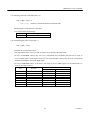
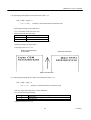
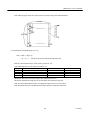
(26) Specifying/Canceling the inverted Characters (ESC {n)
Code : [1B]h + [7B]h + n
* {0 ≤ n ≤ FF}
The data is described with the hexadecimal code.
Specifying/canceling inverted characters.
• "n" is valid only for the lowest bit (n0).
• Bit n (n0) means the followings.
n0
Type
0
Cancels the inverted characters
1
Specifies the inverted characters
• Effective only when specified at the beginning of the lin e.
• Printing example are shown below.
• An initial value of "n" is "0".
When inverted printing
is cancelled
Paper feed direction
Paper feed direction
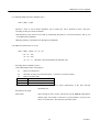
(27) Specifying/canceling the 90°-right- turned characters (ESC V n)
Code : [1B]h + [56]h + n
* {0 ≤ n ≤ 1}
The data is described with the hexadecimal code.
• The 90°-right- turned characters are not underlined.
• "n" has the following meanings.
n (Hex)
Type
0
Cancels the 90°-right- turned characters
1
Specifies the 90°-right- turned characters
• An initial value of "n" is "0".
43
CITIZEN
CBM-230/231 User’s Manual
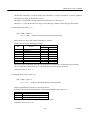
(28) Specifying Absolute Positions (ESC $ n1 n2)
Code : [1B]h + [24]h + n1 + n2
* {0 ≤ n1 ≤ FF}
{0 ≤ n2 ≤ 1}
The data is described with the hexadecimal code.
Specifies the printing start position in terms of the number of dots from the beginning of the line (in an
increment of 1/203 inch).
• The number of dots is divided by 256, and a quotient is assumed to be n2, and the remainder to be n1.
Therefore, the printing start position is n1 + n2 × 256 from the beginning of the line.
• The position specified beyond the end of the line is ignored.
(29) Specifying the relative position (ESC ¥ n1 n2)
Code : [1B]h + [5C]h + n1 + n2
* {0 ≤ n1 ≤ FF}
{0 ≤ n2 ≤ FF}
The data is described with the hexadecimal code.
Specifies the printing start position in terms of the number of dots from the current position (in an
increment of 1/203 inch).
• The right direction is plus (+), and left direction is minus ( –).
• When specifying N dots in the minus (left) direction, specify with a complement of N.
– N dots = 65536 – N
• The number of dots is divided by 256, and a quotient is assumed to be n2, and the remainder to be n1.
• The position specified beyond the end of the line is ignored.
44
CITIZEN
CBM-230/231 User’s Manual
(30) Printing the bar code (GS k n Dn NUL)
Code : [1D]h + [6B]h + n + Dn + [00]h
* {0 ≤ n ≤ 7}
The data is described with the hexadecimal code.
Selects the bar code system and prints the bar code.
• The beginning of the line is assumed to be the next printing start position.
• selects the bar code system listed in the table below, depending on the valu es of "n".
• Dn denotes the characters to be printed.
n (Hex)
Bar code system
0
UPC-A
1
UPC-E
2
JAN13 (EAN)
3
AN 8 (EAN)
4
CODE 39
5
ITF
6
CODABAR
7
CODE 128
• When the data exists in the print buffer, this command is ignored.
• When the character code Dn denotes the unprintable characters, the subsequent data is treated as normal
printing data.
• When you select the bar code system where the fixed number of characters is printed, the number of
characters must coincide with the number of characters printed.
• When the horizontal direction exceeds the length of one line, the surplus portion is not printed.
45
CITIZEN
CBM-230/231 User’s Manual
(31) Selecting Bar Code width (GS w n)
Code : [1D]H + [77]H + n
* {2 ≤ n ≤ 4}
The data is described with the hexadecimal code.
Selects the horizontal size of the bar code.
• An initial value of the horizontal size is "3".
(32) Selecting the height of the bar code (GS h n)
Code : [1D]H + [68]H + n
* {1 ≤ n ≤ FF}
The data is described with the hexadecimal code.
Selects the height of the bar code.
• "n" denotes the number of dots in the vertical direction.
• An initial value of "n" is "162".
(33) Selecting Printing Position of HRI Characters (GS H n)
Code : [1D]H + [48]H + n
* {0 ≤ n ≤ 3}
The data is described with the hexadecimal code.
Selectis the printing position of the HRI characters when printing the bar code.
• "n" has the following meanings.
n (Hex)
Printing Position
0
No printing
1
Above the bar code
2
Below the bar code
3
Both above and below the bar code
• The HRI characters are printed in the font selected by GS f.
• An initial value of "n" is "0".
46
CITIZEN
CBM-230/231 User’s Manual
(34) Selecting the font of the HRI characters (GS f n)
Code : [1D]h + [66]h + n
* {0 ≤ n1 ≤ 1}
The data is described with the hexadecimal code.
Select the font of the HRI characters when printing the bar code.
• "n" has the following meanings.
n (Hex)
Font
0
Font A
1
Font B
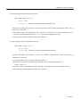
(35) Defining the download bit image (GS * n1 n2 Dn)
Code : [1D]h + [2A]h + n1 + n2 + Dn
* {0 ≤ n1 ≤ FF}
{0 ≤ n2 ≤ 30}
{n1 × n2 ≤ 51F}
The data is described with the hexadecimal code.
Defines the download bit image which has the number of dots specified by n1 and n2.
• The numbers of dots in the horizontal direction assumed to be n1 × 8, and that in the vertical direction to
be n2 × 8.
• Dn denotes the bit image data.
• Once the download bit image is defined, it remains effective until it is redefined, ESC @ is executed,
ESC & is executed, or the power is turned off.
• The download characters and download bit image cannot be defined at the same time. Executing this
command clears the definition of the download characters.
47
CITIZEN
CBM-230/231 User’s Manual
• The folloeing figure shows the relations between the bit image data and defined dots.
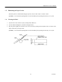
(34) Printing Download Bit Image (GS / m)
Code : [1D]h + [2F]h + m
* {0 ≤ m ≤ 3}
The data is described with the hexadecimal code.
Prints the download bit images in the mode specified by "m".
• The following table lists the mode selected by "m".
m
Mode Name
0
Normal mode
1
Hor. double mode
2
Vert. double mode
3
4-fold mode
Vertical Dot Density
203 DPI
203 DPI
101 DPI
101 DPI
Horizontal Dot Density
203 DPI
101 DPI
203 DPI
101 DPI
• When the data exists in the print buffer, this command is ignored.
• When the download bit image has not been defined, this command is ignored.
• The part of the download bit image exceeding the length of one line is not printed.
• The download characters and download bit image cannot be defined the same time.
48
CITIZEN
CBM-230/231 User’s Manual
(37) Starting/ending the macro definition (GS :)
Code : [1D]h + [3A]h
Specifies a starti or end of macro definition. Up to 2,048 bytes can be defined as macro. The bytes
exceeding 2,048 bytes cannot be defined.
• The definition is not cleared even if ESC @ (initializing the printer) is executed. Therefore, ESC @ can
be included in the definition.
• Regular printing is cperformed even during macro definition
(38) Macro Execution (GS^ n1 n2 n3)
Code : [1D]h + [5E]h + n1 + n2 + n3
* {0 ≤ n1 ≤ FF}
{0 ≤ n2 ≤ FF}
{0 ≤ n3 ≤ 1}
The data is described with the hexadecimal code
Executing what is defined as macro.
• The following describes n1 through n3:
n1
: Macro execution times
n2
: Wait time at macro execution.Wait for n2 × 100 msec for each execution.
n3
: Macro execution mode
n3
Mode
0
Continuous execution
1
Execution by the paper feed switch
Continuous execution
: The macro is executed n1 times continuously at the time intervals
specified by n2.
Execution by the paper
Feed switch
: After waiting for lapse of time specified by n2, the ERROR LED flickers
and the paper feed switch is waited to be pressed. When it is pressed, the
macro is executed once. This action is repeated n1 times.
49
CITIZEN
CBM-230/231 User’s Manual
• When this command is accepted during macro definition, it means cancellation of macro definition.
When this time done, the definition is cleared.
• Nothing is executed when the macro has been undefined or n1=0 has been set.
• When n3 = 1 is set and the macro is being executed, the paper cannet be fed by the paper feed switch.
(39) Data input control (ESC = n)
Code : [1B]h + [3D]h + n
* {0 ≤ n ≤ FF}
The data is described with the hexadecimal code.
Selects the device where data input from the host is effective.
• Each bit of "n" has the following meanings.
Bit
0
1
2
3
4
5
6
7
Device
Printer
Undefined
Undefined
Undefined
Undefined
Undefined
Undefined
Undefined
Value
0
1
Disabled
Enabled
• When the printer id disabled, this printer discards all receive data until it is enabled by this command.
• Even if the printer is disabled, it may be placed in the busy state by printer operation.
• The initial value of "n" is "1".
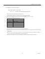
(40) Aligning the characters (ESC a n)
Code : [1B]h + [61]h + n
* {0 ≤ n ≤ 2}
The data is described with the hexadecimal code.
Aligns all printed data in one line to a specified position.
• Justification listed in the following table is performed depending on the value of "n".
n (Hex)
Position
0
Left alignment
1
Center alignment
2
Right alignment
• Effective only when this is entered at the beginning of the line.
• The initial value of "n" is "0".
50
CITIZEN
CBM-230/231 User’s Manual
(41) Full cut (ESC i)
Code : [1B]h + [69]h
Cuts the paper fully.
• Effective only when this is entered at the beginning of the line.
• CBM-231 only.
(42) Partial cut (ESC m)
Code : [1B]h + [6D]h
Cuts the paper partially.
• Effective only when this is entered at the beginning of the line.
• CBM-231 only.
51
CITIZEN
CBM-230/231 User’s Manual
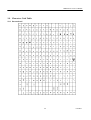
10. Character Code Table
10.1 International
52
CITIZEN
CBM-230/231 User’s Manual
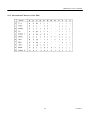
10.2 International Character Code Table
53
CITIZEN
CBM-230/231 User’s Manual
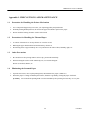
Appendix 1. PRECAUTIONS AND MAINTENANCE
1.1
Precaution for Handling the Printer Mechanism
1. Use of unspecified paper may not assure you of printing quality and product life.
2. With the printing head kept down, do not turn the paper feed knob or pull out the paper.
3. Do not touch the heating element's surface of the head.
1.2
Precautions for Handling the Thermal Paper
1. A contact of chemicals or oil may discolor or erase the record.
2. Rubbing the paper hard with nail or hard metal may discolor it.
3. Discoloring starts at approximately 70°C. Pay attention to an effect of heat, humidity, light, etc.
1.3
Other Precautions
1. Be careful not to drop foreign matter such as clip, pin into the main body.
2. When cleaning the surface of the main body case, use neutral detergent.
Do not use alcohol, thinner, etc.
1.4
Eliminating the Jammed Paper
1. Open the auto cutter, move up the printing head, and eliminate the paper. (CBM-231)
2. When the paper is coiling around the platen roller, eliminate it gradually, turning the paper feed knob.
[Caution]
Do not touch the printing head or motor immediately after printing because they are very hot.
54
CITIZEN
CBM-230/231 User’s Manual
1.5
Eliminating the Paper Powder
When the printer is contaminated with paper powder, clean it with a brush or vacuum cleaner.
[Caution]
1.6
Do not touch the printing head or motor immediately after printing because they are very hot.
Cleaning the Head
1. Open the auto cutter and move up the printing head.(CBM-231)
2. Use the cardboard and gauze as shown in the figure below.
3. Dip the gauze slightly into alcohol, insert it in between the printing head and platen roller as shown in the
figure, and clean by moving it aside.
[Caution]
Do not touch the printing head or motor immediately after printing because they are very hot.
55
CITIZEN
CBM-230/231 User’s Manual
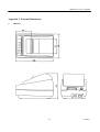
Appendix 2. External Dimensions
1.
CBM-230
56
CITIZEN
CBM-230/231 User’s Manual
2.
CBM-231
57
CITIZEN
CBM-230/231 User’s Manual
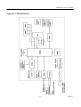
Appendix 3. Block Diagram
58
CITIZEN
Information Systems Division
CBM Bldg., 5-68-10, Nakano, Nakano-ku, Tokyo 164-0001, Japan
Head Office
Tel: (+81-3) 5345-7540 Fax: (+81-3) 5345-7541
21E-20000208-1000-0064-07.55 Printed in Japan