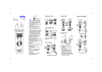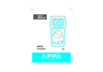
1
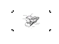
CLAMP MULTIMETER INSTRUCTION MANUAL APPA 33Ⅱ/33RⅡ INTRODUCTION 1-1 Unpacking and Inspection Upon removing your new Digital Clamp Meter from its packing, you should have the following items: 1. Digital Clamp meter. 2. Carrying case. 3. Instruction manual. 4. Test lead set (one black, one red). 1-2 Meter Safety Terms as Marked on Equipment . ATTENTION — Refer to manual. DOUBLE INSULATION — Protection Class Ⅱ DANGER — Risk of electric shock. 1 Symbols in this Manual This symbol indicates where cautionary or other information is found in the manual. Battery. 1-3 Front Panel Refer to Figure 1 and the following numbered steps to familiarize yourself with the meter’s front panel controls and connectors. 1. Digital Display — The digital display has a 3 1/2 digit LCD readout (maximum reading 1999) plus auto polarity, decimal point, and . 2. Input Terminal — The black test lead is always connected to the “COM” input jack and red test lead is always connected to the “V-Ω” input jack when measuring ACV and OHMS. 3. Function Switch — Rotate to desired function. 4. Data Hold Switch — Hold display reading for all functions and ranges. 2 5. Trigger — Press the lever to open the transformer jaws. When the pressure on the lever is released, the jaws will close again. 6. Transformer Jaws — Designed to pick up the AC current flowing through the conductor. 7. Hand Guard — Designed to protect user for safety. 8. Battery Cover. 9. Battery Cover Screw. 3 6 7 4 5 3 9 1 8 2 Figure 1 4 SPECIFICATIONS 2-1 General Specifications Display : 3 1/2 Digital Liquid Crystal Display (LCD) with a maximum reading of 1999. Overrange Indication : “1” indicated, show the real value for “V” function and 600A range of “A” function. Measuring Rate : 4 times per second, nominal. Low Battery Indication : =is displayed when the battery voltage drops below the operating voltage. 2-2 Environmental Conditions Indoor Use. Maximum Altitude : 2000 meter. Installation Category : IEC 1010 600V Cat. Ⅲ Pollution Degree : 2 Operating Ambient : 0°C to + 45°C (below 75% R.H.) Storage Temperature : -20°C to + 60°C (below 80% R.H.) with battery removed. 5 Temperature Coefficient : 0.2 x (Spec.Acc'y) / °C , < 18 °C or > 28°C. Power Requirement : Single 9V battery (NEDA 1604,IEC 6F22) Battery Life : Alkaline 400 hours. Shock Proof : 4 feet drops. Maximum Jaw Opening : 42mm Maximum Conductor Size : 40mm diameter. Size : 200mm (W) x 76mm (L) x 41mm (H) Weight : 360gms (including battery) Accessories : Test leads, battery , manual and carrying case. 6 2-3 Electrical Specifications Accuracy is ±(%reading + number of digits) at 23 °C ± 5 °C , less than 75% R.H. (1) AC Voltage : Auto-ranging Range Resolution Accuracy Overload protection 600V 1V ±(1.2%rdg + 3dgt) 40Hz ~ 500Hz 600V r.m.s. * AC Conversion Type : Average Sensing rms indication. (33Ⅱ) AC Conversions are ac-coupled, true rms responding , calibrated to the rms value since wave input , the basic accuracy is for sine wave at full scale, for non-sine wave accuracy reference to ** (33RⅡ) ** Crest Factor : 2 to 3 , add 1.4% to Accuracy. 3 to 4 , add 3% to Accuracy. Input impedance : 2MΩ // 2nF approx. 7 (2) AC Current : Auto-ranging Range Resolution 200A 0.1A 600A 1A Accuracy Overload protection ±(1.9%rdg + 5dgt) 50/60Hz ±(1.5%rdg + 5dgt) 50/60Hz (for 0 ~ 400A) ±(2.5%rdg + 5dgt) 50/60Hz (for 400 ~ 600A) 800A * AC Conversion Type : Average Sensing rms indication. (33Ⅱ) AC Conversions are ac-coupled, true rms responding , calibrated to the rms value since wave input , the basic accuracy is for sine wave at full scale, for non-sine wave accuracy reference to ** (33RⅡ) ** Crest Factor : 2 to 3 , add 1.4% to Accuracy. 3 to 4 , add 3% to Accuracy. 8 (3) Resistance : Auto - ranging Range Resolution Accuracy Max. Open Circuit Voltage Over voltage protection 2000Ω 1Ω ±(1.5%rdg + 2dgt) 3V 600V r.m.s. (4) Instant Continuity Description : Built - in buzzer sound when resistance is less than approximately 50Ω . (5) Data Hold : Hold display reading for all functions and ranges. (6) Auto Power Off : Once the Clamp-On meter is powered on, a timer is activated which will turn the unit off after approximately 30 minutes. If you wish to continue marking measurements after the unit automatically powers off, you must switch the function selector to “OFF” and then back to the desired function. 9 OPERATION This instrument has been designed and tested in accordance with IEC Publication 1010, Safety Requirements for Electronic Measuring Apparatus and has been supplied in a safe condition. This instruction manual contains some information and warnings which have to be followed by the user to ensure safe operation and to retain the instrument in safe condition. 3-1 Precautions and Preparations for measurement 1. Make sure that the battery is properly connected. 2. The instrument should only be operated between 0°C ~ 45°C and at less than 75% R.H. 3. Do not use or store this instrument in a high temperature or high humidity environment and do not store the unit in direct sunlight. 4. Do not replace battery with power on condition. 5. If the unit is not to be used for a long period of time, remove the battery. 6. Do not forget to turn off after use. 10 7. If the meter is used near equipment that generates electromagnetic noise, the display may be unstable or indicate large errors. 8. Maximum rated voltage to earth for voltage measurements terminals is 600V CAT. Ⅲ. 9. When using the instrument as a Voltmeter or ohmmeter never clamp the jaws around or onto a conductor. THIS INSTRUMENT MUST NOT BE USED ON UNINSULATED CONDUCTORS AT A VOLTAGE GREATER THAN 600V ac/dc. 3-2 AC Current Measurement 1. Set the function switch at desired current position. 2. Open Spring-loaded clamp by pressing trigger on right side of meter. 3. Position clamp around wire or conductor and release clamp trigger, make sure that the clamp is entirely closed. The clamp must be positioned around only one conductors of a circuit . If the clamp is placed around two or more current carrying conductors, the meter reads FALSE. 11 3-3 AC Voltage Measurement 1. Set the function switch at " V ~ " position. 2. Connect the black test lead to the "COM" terminal and the red test lead to the " V-Ω" terminal. You can now place the test probes on the conductors to make the measurement. 3-4 Resistance Measurement 1. Set the function switch at " Ω " position. 2. Connect the black test lead to the "COM" terminal and red test lead to the " V– Ω " terminal. 3. Verify that the power to the circuit under test is off. Connect test leads to the circuit to make the measurement. 4. Built in buzzer sounds if the resistance of the circuit under test is less than approximately 50Ω. 12 MAINTENANCE WARNING : TO AVOID ELECTRICAL SHOCK REMOVE TEST LEAD BEFORE OPENING THE COVER. 4-1 General Maintenance 1. Repairs or servicing not converted in this manual should only be performed by qualified personal. 2. Periodically wipe the case with a dry cloth and detergent do not use abrasives or solvents. 4-2 Battery Replacement WARNING : Before opening the battery cover, remove the test leads (or jaw) from the circuit and shut off the unit. 1. Disconnect the unit from the circuit. Turn the unit OFF. 2. Remove the battery cover screw. 3. Remove the battery cover. 4. Replace the battery (observe polarity). 5. Replace the cover and the screw. 13 Screw Battery Cover 9V Battery Top Case Bottom Case Figure 2 14 APPA TECHNOLOGY CORP. 9F.119-1 Pao-Zong Rd., Shin-Tien, Taipai, 23115, Taiwan, R.O.C. P.O.Box. 12-24 Shin-Tien, Taiwan. Tel : 886-2-29178820 Fax : 886-2-29170848 E-MAIL:info @appatech.com http://www.appatech.com Copright 2001, APPA Tech., Corp. All rights reserved. Printed In Taiwan 71-10660-1