1
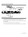
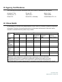
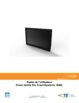
USER MANUAL
Elo Touch Solutions
2440L Touchmonitor
SW602154 Rev A
Copyright © 2013 Elo Touch Solutions, Inc. All Rights Reserved.
No part of this publication may be reproduced, transmitted, transcribed, stored in a retrieval system, or translated
into any language or computer language, in any form or by any means, including, but not limited to, electronic,
magnetic, optical, chemical, manual, or otherwise without prior written permission of Elo Touch Solutions, Inc.
Disclaimer
The information in this document is subject to change without notice. Elo Touch Solutions, Inc. and its Affiliates
(collectively "Elo") makes no representations or warranties with respect to the contents herein, and specifically
disclaims any implied warranties of merchantability or fitness for a particular purpose. Elo reserves the right to
revise this publication and to make changes from time to time in the content hereof without obligation of Elo to
notify any person of such revisions or changes.
Trademark Acknowledgments
AccuTouch, CarrollTouch, Elo, Elo (logo), Elo Touch, Elo Touch Solutions, Elo TouchSystems, IntelliTouch, iTouch,
SecureTouch, TouchTools and VuPoint are trademarks of Elo and its Affiliates. Windows is a trademark of Microsoft
Corporation.
User Manual: 2440L
SW602154 Rev A, Page 2 of 34
Table of Contents
Chapter 1: Introduction ............................................................................ 4
Chapter 2: Installation .............................................................................. 5
Chapter 3: Mounting ............................................................................... 13
Chapter 4: Operation .............................................................................. 16
Chapter 5: Technical Support ................................................................ 24
Chapter 6: Safety & Maintenance .......................................................... 26
Chapter 7: Regulatory Information ........................................................ 28
Chapter 8: Warranty Information ........................................................... 33
User Manual: 2440L
SW602154 Rev A, Page 3 of 34
Chapter 1: Introduction
Product Description
Your new touchmonitor combines the reliable performance of Elo Touch Solutions touch
products with the latest developments in touchscreen technology and display design. This
combination of features ensures a product with stable, drift-free operation, consistent reliability
and durability, backed by a 3-year standard warranty.
This open-frame touchmonitor delivers a professional-grade display in a slim, integrated
package. It incorporates a pure-glass touchscreen for optimal image quality, a high quality
panel and multiple mounting options. Its LED backlight significantly reduces power consumption
and eliminates mercury (compared to CCFL-backlit panels). The true-flat edge-to-edge design
gives integrators an additional advantage in developing the most aesthetically pleasing
products
Precautions
Follow all warnings, precautions and maintenance as recommended in this user manual to
maximize the life of your unit and prevent risks to user safety. See the Safety & Maintenance
chapter for more information.
This manual contains information that is important for the proper setup and maintenance of the
unit. Before setting up and powering on your new touchmonitor, read through this manual,
especially the Installation, Mounting, and Operation chapters.
User Manual: 2440L
SW602154 Rev A, Page 4 of 34
Chapter 2: Installation
Unpacking the Touchmonitor
Open the carton and verify that the following items are present:
• Touchmonitor with protective sheet for its face
• User Manuals CD
• Japanese language regulatory information pamphlet
• Quick Install Guide
• VGA cable
• DVI cable
• USB cable (not available for no touch models)
• Serial cable (available for single touch models only)
• Mounting brackets and screws
• OSD Remote
User Manual: 2440L
SW602154 Rev A, Page 5 of 34
Connector Panel & Interfaces
Touchmonitor Connections
1. Connect the DVI or VGA video cables between the monitor’s DVI/VGA input connectors and
your DVI/VGA video source. Tighten the video cable’s screws for best performance.
2. Connect the USB or serial touch cable between the monitor’s USB/serial connector and your
PC’s USB/serial port.
3. Connect a 12VDC power supply to the monitor’s input power jack.
4. The touchmonitor ships in an ON state, video should be displayed on your monitor already.
User Manual: 2440L
SW602154 Rev A, Page 6 of 34
Installing the Touch Technology Software Drivers
Some software installation is required for your touchmonitor to work with your computer. No
additional drivers are required for your projected-capacitive touchmonitor, it uses Windows HID
drivers.
The drivers are available on the Elo Touch Solutions website.
Visit www.elotouch.com for:
• The most up-to-date touch driver versions
• Additional touch driver information
• Detailed touch driver installation guides
• Touch drivers for other operating systems
User Manual: 2440L
SW602154 Rev A, Page 7 of 34
Select the applicable driver from the Elo Touch Solutions website and download:
For Windows 7 installations, double-click on EloSetup Installer
User Manual: 2440L
SW602154 Rev A, Page 8 of 34
After accepting the end-user license agreement, the system will initialize to setup installation of
drivers.
To complete setup, reboot system by clicking on “Reboot Now” button. Click on “One More
Minute” if more time is needed with increments of 1 minute.
User Manual: 2440L
SW602154 Rev A, Page 9 of 34
Note: System will automatically reboot when “Time left” counter reaches “0”.
For Windows XP installations, double-click on the icon from the desktop
User Manual: 2440L
SW602154 Rev A, Page 10 of 34
Click on “Unzip” button to unzip files.
User Manual: 2440L
SW602154 Rev A, Page 11 of 34
Select one or more of the drivers to install. Click on “Next”
After accepting the end-user license agreement, the drivers will finish installing.
Reboot your computer after the install is complete.
User Manual: 2440L
SW602154 Rev A, Page 12 of 34
Chapter 3: Mounting
General Mounting Information
The OSD text can be rotated through the OSD menu to better suit your mounting orientation.
Side Bracket Mount (IntelliTouch and No Touch models only)
Threaded holes are provided on the sides of the monitor for mounting using the provided
brackets.
User Manual: 2440L
SW602154 Rev A, Page 13 of 34
Flush Bracket Mount (iTouch and Projected Capacitive models
only)
Threaded holes are provided on the back of the monitor for mounting using the provided
brackets.
User Manual: 2440L
SW602154 Rev A, Page 14 of 34
Rear VESA Mount (All models)
A four-hole 200x100mm mounting pattern for M4 screws is provided on the rear of the monitor.
The VESA FDMI-compliant counting is coded: VESA MIS-D, 200mm x 100mm.
User Manual: 2440L
SW602154 Rev A, Page 15 of 34
Chapter 4: Operation
Power
The touchmonitor ships in an ON state.
To turn the touchmonitor on or off, press the touchmonitor power button on the OSD controller
once.
The Power Status LED on the OSD controller functions according to the following table:
Touchmonitor status
LED status
OFF
OFF
SLEEP
PULSING
ON
ON
The system consumes low power when in SLEEP and OFF modes. For detailed power
consumption specifications, refer to technical specifications on the Elo website
http://www.elotouch.com
Touching the screen will bring the attached host PC out of SLEEP mode (similar to moving the
mouse or pressing a keyboard key).
To improve reliability and reduce wasteful power consumption, disconnect the AC power cable
from the monitor when long periods of disuse are planned.
Touch
Your touchmonitor is factory-calibrated and should not need manual calibration (unless the
input video is not fully scaled to the native resolution, or the touch experience needs to be
calibrated to a specific user).
IntelliTouch/iTouch Plus Touchscreen Technology
When connected to Windows 7 computers, the touchmonitor can report two simultaneous
touches. The IntelliTouch/iTouch Plus touchscreen can be re-calibrated to your displayed video
image, if needed, through the Calibration function in the Elo driver control panel.
The IntelliTouch/iTouch Plus driver will only support multiple monitor if they are all using the
User Manual: 2440L
SW602154 Rev A, Page 16 of 34
IntelliTouch/iTouch Plus touchscreen technology.
To use multiple IntelliTouch/iTouch Plus monitors, plug in monitors to calibrate, double-click
on the EloConfig desktop shortcut to run Elo Touchscreen Configuration screen.
Click on “Calibrate Touch Screens…” to calibrate multiple monitors.
User Manual: 2440L
SW602154 Rev A, Page 17 of 34
Tap monitor screen to identify monitor’s identity as shown below.
Identity of the monitor will display. Click on “OK” to proceed to calibration.
User Manual: 2440L
SW602154 Rev A, Page 18 of 34
Calibrate touch as targets appear on corners of the screen. Follow instructions on screen.
Test touch/drag performance to verify calibration accuracy, “Accept” or “Retry” to redo
calibration process.
Run touch calibration on each monitor that is plugged in.
User Manual: 2440L
SW602154 Rev A, Page 19 of 34
Projected Capacitive Touch Technology
When connected to Windows 7 computers, the touchmonitor can report 2 simultaneous
touches. When connected to Windows XP computers, the touchmonitor reports single touches.
No additional drivers are required for this technology to work, it uses Windows HID drivers.
No calibration is required for this technology.
Gesture Support
The IntelliTouch/iTouch Plus and Projected Capacitive touch technologies enable several
gestures that support single and multiple touches. Refer to the Microsoft Website
http://msdn.microsoft.com/en-us/library/dd940543 on the various gestures that are supported in
Windows 7.
Video
A display’s native resolution is its width and height measured in number of pixels. Generally, for
best performance, an image displayed on this monitor will look best when your computer’s
output resolution matches this monitor’s native resolution of 1920 x 1080.
For computer output resolutions at non-native resolutions, the monitor will scale the video to its
panel’s native resolution. This involves stretching or compressing the input image as needed in
the X- and Y-dimensions to fit the display’s native resolution. An unavoidable byproduct of the
scaling algorithms is a loss of fidelity when the computer’s output video image is scaled by the
monitor to fit the display. This loss of fidelity is most apparent when viewing feature-rich images
at close distances (for example images containing small-font text).
Your touchmonitor will likely not require video adjustments. However, for analog VGA video,
variations in video graphic card outputs may require user adjustments through the OSD to
optimize the quality of the touchmonitor’s displayed image. These adjustments are
“remembered” by the touchmonitor. Also, to reduce the need for adjustments for different video
mode timings, the monitor correctly scales and displays some of the video industry’s most
common video timing modes. Refer to the technical specifications for this monitor at
http://www.elotouch.com for a list of these Preset Video Modes.
User Manual: 2440L
SW602154 Rev A, Page 20 of 34
On-Screen Display (OSD)
Four OSD buttons are located on a wired control box. These can be used to adjust various
display parameters.
The buttons and their functionality are:
Button
Function when OSD is not displayed:
Menu Display OSD main menu
Display OSD Contrast submenu
Display OSD Brightness submenu
Select Display Video Source submenu
Function when OSD is displayed:
Return to previous OSD menu
Decrease value of selected parameter /
select next menu item
Increase value of selected parameter /
select previous menu item
Select parameter for adjustment /
select submenu to enter
Using the OSD buttons controls an on-screen graphical user interface which displays on top of
your input video, allowing intuitive adjustment of the following display parameters:
Parameter
Available Adjustment
Increase/decrease monitor brightness.
Brightness
Default: maximum
Increase/decrease monitor contrast.
Contrast
Default: best gray-shade performance
Allows fine adjustments of the panel’s pixel dot clock.
Clock
Only applicable for VGA input video
Allows fine adjustments of the panel’s pixel dot clock phase.
Phase
Only applicable for VGA input video
Automatically adjusts the system clock to the input analog VGA video signal,
Auto Adjust affecting the H-position, V-position, Clock, and Phase menu items.
Only applicable for VGA input video
Moves the image horizontally on the display in single-pixel increments.
H-position Default: centered.
Only applicable for VGA input video
Moves the image vertically on the display in single-pixel increments.
V-position Default: centered.
Only applicable for VGA input video
User Manual: 2440L
SW602154 Rev A, Page 21 of 34
Switches the scaling method between Full Scaling and Maintain Aspect Ratio.
Default: Full Scaling
Aspect
Ratio
Full Scaling – scales the X- and Y-dimensions of the input video (up or down as
needed) to the display’s native resolution.
Fill To Aspect Ratio – Assuming a landscape orientation and an input video with
aspect ratio smaller than 1920 x 1080, scales the Y-dimension of the input video
(up or down as needed) to the display’s Y-resolution, and scales the X-dimension
to maintain the input video’s aspect ratio (and fills the rest of the display with
equal black bars on the left and right).
The touchscreen may need recalibration when switching between Aspect Ratio
options.
Adjusts sharpness of the displayed images.
Sharpness Default: no sharpness adjustment
Only applicable at non-native input video resolutions
Selects the display’s color temperature. The available color temperatures are
9300K, 7500K, 6500K, 5500K, and User Defined. If the User Defined option is
Color
selected, the user can change the color temperature by changing individual R, G,
Temperature
and B gains on a scale from 0 to 100.
Default: User Defined with R, G, and B all set to 100.
OSD
Adjusts the horizontal location of the OSD menus on the display
H-Position Default: centered.
OSD
Adjusts the vertical location of the OSD menus on the display.
V-Position Default: centered.
Adjusts how long a period of OSD button inactivity the touchmonitor will wait
OSD
before closing the OSD. The adjustable range is between 5 and 60 seconds.
Timeout
Default: 15 seconds
Selects which language the OSD information is displayed in. The available
OSD
languages are: English, French, Italian, German, Spanish, Simplified Chinese,
Language Traditional Chinese, and Japanese.
Default: English.
Selects the touchmonitor mounting orientation between Landscape and Portrait
OSD
to match your physical orientation. This adjusts the rotation of the OSD text
Rotation
Default: Landscape
Selecting “Recall Defaults” restores all factory default settings for
Recall
OSD-adjustable parameters (except OSD Language) and for Preset Video Mode
Defaults
timings.
The monitor continually scans for active video on the VGA and DVI connectors.
This adjustment selects which of those input ports should be given priority to be
Video
displayed.
Source
The options are: VGA Priority, DVI Priority
Default: DVI Priority
All touchmonitor adjustments made through the OSD are automatically memorized as soon as
they are entered. This feature saves you from having to reset your choices every time the
touchmonitor is unplugged or powered off and on. If there is a power failure, the touchmonitor
settings will not default to the factory specifications.
User Manual: 2440L
SW602154 Rev A, Page 22 of 34
OSD and Power Lockouts
Press and hold the “Menu” and “ ” buttons for two seconds to enable/disable the OSD Locking
feature. When the OSD Locking is enabled, pressing any of the “Menu”, “ ”, “ ”, or “Select”
keys will have no effect on the system.
Press and hold the “Menu” and “ ” buttons for two seconds to enable/disable the Power
Locking feature. When the Power Locking is enabled, pressing the power switch will have no
effect on the system.
User Manual: 2440L
SW602154 Rev A, Page 23 of 34
Chapter 5: Technical Support
If you are experiencing trouble with your touchmonitor, refer to the following suggestions.
If the problem persists, please contact your local dealer or contact Elo Touch Solutions
Customer Service. Worldwide technical support phone numbers are available on the last page
of this use manual.
Solutions to Common Problems
Problem
The touchmonitor does not respond
when turning on the system
Suggested Troubleshooting
Check that the DC power adaptor is properly
connected
Verify the DC power adaptor is functioning
Monitor display is dim
Use the OSD to increase the brightness.
Use the OSD to increase the contrast.
Monitor display is blank
If the Power Status LED is blinking, the monitor or
Computer Module may be in SLEEP mode. Press any
key / move the mouse / touch the touchscreen to see if
the image reappears.
Check that the signal source device is turned on.
Check that that there are no loose cable connections.
Monitor displays an “Out Of Range”
message
Adjust your computer’s resolution/timing mode to be
within the allowable timing ranges specified for your
touchmonitor (see website for specifications)
Monitor display image looks strange
Adjust your computer’s resolution/timing mode to be
within the allowable timing ranges specified for your
touchmonitor (see website for specifications)
Use the Auto Adjust function in the OSD
Touch functionality doesn’t work
Verify your PC has the latest Elo drivers installed.
Perform the calibration routine provided with the latest
Elo drivers.
The OSD buttons or power button does
not respond when pressed
Check to see if the OSD lock or power lock functions
are on
User Manual: 2440L
SW602154 Rev A, Page 24 of 34
Technical Assistance
Visit www.elotouch.com/products for technical specifications for this device
Visit www.elotouch.com/go/websupport for online self-help.
Visit www.elotouch.com/go/contactsupport for technical support.
See this user manual’s last page for worldwide technical support phone numbers.
User Manual: 2440L
SW602154 Rev A, Page 25 of 34
Chapter 6: Safety & Maintenance
Safety
To avoid risk of electric shock, follow all safety notices and do not disassemble the
touchmonitor. They are not user-serviceable.
Ensure that your installation is equipped to maintain the specified environmental conditions
listed in the Technical Specifications chapter.
Care and Handling
The following tips will help keep your touchmonitor functioning at an optimal level:
• Disconnect the AC power cable before cleaning.
• To clean the display unit cabinet, use a clean cloth lightly dampened with a mild detergent.
• It is important that your unit remains dry. Do not get liquids on or inside the unit. If liquid
does get inside, turn the unit off and have a qualified service technician check it before
you power it on again.
• Do not wipe the screen with a cloth or sponge that could scratch the surface.
• To clean the touchscreen, use window or glass cleaner applied to a clean cloth or sponge.
Never apply the cleaner directly to the touchscreen. Do not use alcohol (methyl, ethyl or
isopropyl), thinner, benzene, or other abrasive cleaners.
• Ensure the environmental temperature and humidity are maintained within specification
and do no block ventilation slots.
• Monitors are not designed for outdoors.
User Manual: 2440L
SW602154 Rev A, Page 26 of 34
Waste Electrical & Electronic Equipment Directive (WEEE)
This product should not be disposed of with household waste. It should be
deposited at a facility that enables recovery and recycling.
User Manual: 2440L
SW602154 Rev A, Page 27 of 34
Chapter 7: Regulatory Information
I. Electrical Safety Information:
Compliance is required with respect to the voltage, frequency, and current requirements
indicated on the manufacturer’s label. Connection to a different power source than those
specified herein will likely result in improper operation, damage to the equipment or pose a fire
hazard if the limitations are not followed.
There are no operator serviceable parts inside this equipment. There are hazardous voltages
generated by this equipment which constitute a safety hazard. Service should be provided only
by a qualified service technician.
Contact a qualified electrician or the manufacturer if there are questions about the installation
prior to connecting the equipment to mains power.
II. Emissions and Immunity Information
Notice to Users in the United States: This equipment has been tested and found to comply with
the limits for a Class B digital device, pursuant to Part 15 of FCC Rules. These limits are
designed to provide reasonable protection against harmful interference in a residential
installation. This equipment generates, uses, and can radiate radio frequency energy, and if not
installed and used in accordance with the instructions, may cause harmful interference to radio
communications.
Notice to Users in Canada: This equipment complies with the Class B limits for radio noise
emissions from digital apparatus as established by the Radio Interference Regulations of
Industrial Canada.
Notice to Users in the European Union: Use only the provided power cords and interconnecting
cabling provided with the equipment. Substitution of provided cords and cabling may
compromise electrical safety or CE Mark Certification for emissions or immunity as required by
the following standards:
This Information Technology Equipment (ITE) is required to have a CE Mark on the
Manufacturer’s label which means that the equipment has been tested to the following
Directives and Standards: This equipment has been tested to the requirements for the CE Mark
User Manual: 2440L
SW602154 Rev A, Page 28 of 34
as required by EMC Directive 2004/108/EC as indicated in European Standard EN 55022 Class
B and the Low Voltage Directive 2006/95/EC as indicated in European Standard EN 60950.
General Information to all Users: This equipment generates, uses and can radiate radio
frequency energy. If not installed and used according to this manual the equipment may cause
interference with radio and television communications. There is, however, no guarantee that
interference will not occur in any particular installation due to site-specific factors.
1) In order to meet emission and immunity requirements, the user must observe the following:
a) Use only the provided I/O cables to connect this digital device with any computer.
b) To ensure compliance, use only the provided manufacturer’s approved line cord.
c) The user is cautioned that changes or modifications to the equipment not expressly
approved by the party responsible for compliance could void the user’s authority to operate
the equipment.
2) If this equipment appears to cause interference with radio or television reception, or any
other device:
a) Verify as an emission source by turning the equipment off and on.
If you determine that this equipment is causing the interference, try to correct the interference
by using one or more of the following measures:
i) Move the digital device away from the affected receiver.
ii) Reposition (turn) the digital device with respect to the affected receiver.
iii) Reorient the affected receiver’s antenna.
iv) Plug the digital device into a different AC outlet so the digital device and the receiver
are on different branch circuits.
v) Disconnect and remove any I/O cables that the digital device does not
use.(Unterminated I/O cables are a potential source of high RF emission levels.)
vi) Plug the digital device into only a grounded outlet receptacle. Do not use AC adapter
plugs. (Removing or cutting the line cord ground may in crease RF emission levels and
may also present a lethal shock hazard to the user.)
If you need additional help, consult your dealer, manufacturer, or an experienced radio or
television technician.
User Manual: 2440L
SW602154 Rev A, Page 29 of 34
III. Agency Certifications
The following certifications and marks have been issued or declared for this monitor:
Australia C-Tick
Europe CE
Mexico CoC
Canada CUL, IC
Japan VCCI
Taiwan BSMI
China CCC
Korea KCC, e-Standby
United States FCC, UL
IV. China RoHS
In accordance to Chinese law (Administration on the Control of Pollution Caused by Electronic
Information Products), the section below lists out the name and amount of the toxic and/or
hazardous materials that this product may contain.
Component Toxic or Hazardous Substances and Elements
Name
Lead(Pb) Mercury(Hg) Cadmium(Cd) Hexavalent Polybrominated Polybrominated
Chromium Biphenyls
Diphenyl
(Cr6+)
(PBB)
Ethers (PBDE)
Plastic
O
O
O
O
O
O
Parts
Metal Parts X
O
O
O
O
O
Wire and X
O
O
O
O
O
Cable
Assembly
LCD Panel X
O
O
O
O
O
Touch
X
O
O
O
O
O
Screen
Panel
PCBA
X
O
O
O
O
O
Software O
O
O
O
O
O
(CD, etc.)
O: Indicates that this toxic or hazardous substance contained in all of the homogeneous
materials for this component is below the limit requirement in SJ/T11363-2006.
X: Indicates that this toxic or hazardous substance contained in at least one of the
homogeneous materials used for this component is above the limit requirement in
SJ/T11363-2006. For items marked with X, exemptions were taken according to EU RoHS.
User Manual: 2440L
SW602154 Rev A, Page 30 of 34
Explanation of Markings
(1). In accordance with the SJ/T11364-2006 requirement, the electronic information products
are marked with the following pollution control logo. The Environment-Friendly Use Period for
this product is 10 years. The product will not leak or mutate under normal operating conditions
listed below, so that the use of this electronic information product will not result in any severe
environmental pollution, any bodily injury, or damage to any assets.
Operating Temperature:0-40 / Humidity:20%-80% (non-condensing).
Storage Temperature:-20~60 / Humidity:10%~90% (non-condensing).
(2). It is encouraged and recommended that this product (and all packaging materials) be
recycled and reused according to local laws. The product should not be thrown away casually.
V. Power Adapter Specifications
Electrical Ratings:
Input: 100 - 240VAC, 50/60Hz
Output: 12VDC, minimum 4.16A, LPS
(Power adapter needs to be UL approved)
VI. Monitor Specifications
Electrical Ratings:
Input: 12VDC, 3A
User Manual: 2440L
SW602154 Rev A, Page 31 of 34
Operating Conditions:
Temperature: 0°C - 40°C
Humidity: 20% to 80% (non-condensing)
Altitude: 0 to 3,048m
Storage Conditions:
Temperature: -20°C - 60°C
Humidity: 10% to 95% (non-condensing)
Altitude: 0 to 12,192m
User Manual: 2440L
SW602154 Rev A, Page 32 of 34
Chapter 8: Warranty Information
See http://www.elotouch.com/Support/warranty.asp for more information.
User Manual: 2440L
SW602154 Rev A, Page 33 of 34
Check out Our Website!
www.elotouch.com
Get the latest...
• Product Information
• Specifications
• Upcoming events
• Press releases
• Software drivers
Getting in Touch with us
To find out more about the extensive range of Elo touch solutions, visit our website at
www.elotouch.com, or simply call the office nearest you:
North America
Elo Touch Solutions
1033 McCarthy Blvd
Milpitas, CA 95035
Tel 800-ELO-TOUCH
Tel +1-408-597-8000
Fax +1-408-597-8050
[email protected]
Europe
Tel +32(0)(16)704 500
Fax +32(0)(16)704 549
[email protected]
Asia-Pacific
Tel +86 (21) 3329 1385
Fax +86 (21) 3329 1400
www.elotouch.com.cn
Latin America
Tel +1 786-923-0251
Fax +1 305-931-0124
www.elotouch.com.ar
Copyright 2013 Elo Touch Solutions, Inc. All rights reserved.
User Manual: 2440L
SW602154 Rev A, Page 34 of 34