1
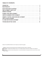
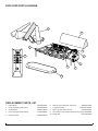
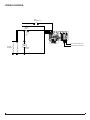
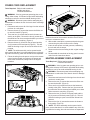
Service Manual
Model
DLG1058
Part Number
6908400100
IMPORTANT SAFETY INFORMATION: Always read this manual first before attempting to service this log grate. For your
safety, always comply with all warnings and safety instructions contained in this manual to prevent personal injury or property damage.
Dimplex North America Limited
1367 Industrial Road Cambridge ON Canada N1R 7G8
1-888-346-7539 www.dimplex.com
In keeping with our policy of continuous product development, we reserve the right to make changes without notice.
© 2012 Dimplex North America Limited
REV
PCN
DATE
00
-
9-AUG-12
7400600000R00
TABLE OF CONTENTS
Operation. . . . . . . . . . . . . . . . . . . . . . . . . . . . . . . . . . . . . . . . . . . . . . . . . . . . . . . . . 3
Maintenance . . . . . . . . . . . . . . . . . . . . . . . . . . . . . . . . . . . . . . . . . . . . . . . . . . . . . . 4
Exploded Parts Diagram. . . . . . . . . . . . . . . . . . . . . . . . . . . . . . . . . . . . . . . . . . 5
Replacement Parts List. . . . . . . . . . . . . . . . . . . . . . . . . . . . . . . . . . . . . . . . . . . 5
Wiring Diagram. . . . . . . . . . . . . . . . . . . . . . . . . . . . . . . . . . . . . . . . . . . . . . . . . . . . 6
Power Cord Replacement. . . . . . . . . . . . . . . . . . . . . . . . . . . . . . . . . . . . . . . . . 7
Heater Assembly Replacement. . . . . . . . . . . . . . . . . . . . . . . . . . . . . . . . . . . . 7
Remote Control Receiver Replacement . . . . . . . . . . . . . . . . . . . . . . . . . . 8
Switch Replacement . . . . . . . . . . . . . . . . . . . . . . . . . . . . . . . . . . . . . . . . . . . . . . 8
Flicker Motor Replacement . . . . . . . . . . . . . . . . . . . . . . . . . . . . . . . . . . . . . . 9
Troubleshooting Guide. . . . . . . . . . . . . . . . . . . . . . . . . . . . . . . . . . . . . . . . . . 10
Always use a qualified technician or service agency to repair this log grate.
! NOTE: Procedures and techniques that are considered important enough to emphasize.
CAUTION: Procedures and techniques which, if not carefully followed, will result in damage to the equipment.
Warning: Procedures and techniques which, if not carefully followed, will expose the user to the risk of fire, serious
injury, or death.
2
www.dimplex.com
Operation
Figure 2
B
Figure 1
C
Unlocked
Batteries
Locked
Child Lock Tab
3. Ensure Child Lock is in the “unlocked” position (Figure
A
The manual controls for the Log Grate are located in the
front right side. (Figure 1)
A. On/Off Switch
Supplies power to the 2-Position Switch.
B. 2-Position Switch
The 2-Position Switch toggles the unit between Manual
Operation and Remote Operation.
• Remote (Front Position): The unit is operated with the
remote control.
• Manual (Back Position): The unit operates with the
flames, logs and ember bed. When the manual control
is in the Manual position the heater does not run.
! NOTE: When the manual control switch is in the Manual
position, the Log Grate unit will not operate with the
remote control.
C. Initialization Button
Used to synchronize the supplied remote control with the
Log Grate.
Resetting the Temperature Cutoff Switch
Should the heater overheat, an automatic cutout will turn
the heater off and it will not come back on without being
reset. It can be reset by switching the On/Off Switch to Off
and waiting 5 minutes before switching the unit back on.
CAUTION: If you need to continuously reset the heater,
unplug the unit and call Dimplex North America Limited at
1-800-668-6663.
Remote Control
The remote control has a range of approximately 50 feet
(15.25 m), it does not have to be pointed at the Log Grate
and can pass through most obstacles (including walls). It
is supplied with 243 independent frequencies to prevent
interference with other units.
Battery Installation
1. Depress tab on the battery cover on the back of the
remote control and remove battery cover.
2. Install two (2) AAA batteries into the remote control
(included).
2).
4. Replace the battery cover.
! NOTE: When the “BAT” symbol is present on the
remote control it is recommended to replace the
batteries promptly, to maintain full functionality of the
remote/Log Grate. The remote control has a battery
backup time of only several hours.
Battery must be recycled or disposed of properly.
Check with your Local Authority or Retailer for
recycling advice in your area.
Remote Control Initialization/Reprogramming
1. Plug cord into 120 Volt wall outlet.
2. Ensure the On/Off Switch (Figure 1A)
(ON) position.
3. Set the 2-Position Switch (Figure 1B) to the Remote
position (front position).
4. Press and hold the Initialization Button on the unit
(Figure 1C).
5. While holding the Initialization Button, press the Flame/
Heat On/Off
button on the remote control.
6. Release the Initialization Button on the unit.
7. Press the Flame/Heat On/Off button
Flame/Heat function On.
to turn the
Frequency Interference
If the Log Grate does not respond properly to the remote
control, the remote operating frequency may have to be
reset. The remote control can send another frequency code
to the remote control receiver to eliminate interference.
1. Simultaneously press the “Temperature Down” button
and the “Flame Speed Down” button on the remote
control (Figure 3).
2. “COD” will appear in place of the sleep timer digits.
3. Release the “Temperature Down” button and the
“Flame Speed Down” button.
4. Press the Initialization Button on the unit (Figure 1C).
5. Press the Flame/Heat On/Off Button
button on the
remote.
Your remote will now have a different frequency
communicating with the Log Grate.
3
Figure 3 - Remote Control Functions
A.
B.
C.
D.
E.
F.
G.
H.
I.
J.
K.
L.
M.
N.
Room Temperature
Set Temperature
Dimmer
Flame Speed Control
Sleep Timer
Flame & Heat On/Off
Temperature Down
Temperature Up
Dimmer Down
Dimmer Up
Flame Speed Down
Flame Speed Up
Sleep Timer Down
Sleep Timer Up
on a thermostat. Press the H or G buttons to adjust the
set temperature. Once the desired set temperature is
reached the heater will turn off. The heater will cycle on
and off to maintain the desired set temperature.
A
B
G
I
K
C
D
H
J
L
M
N
F
E
Remote Control Functions
(All letter references are to Figure 3)
B. Set Temperature
Press F button ( ) to turn Log Grate on.
Press H to raise the thermostat.
Press G to lower the thermostat.
Press both H and G to change °F to °C.
C. Light Dimmer
Press the F button ( ) to turn the Flame/Heat on.
Repeatedly press the J or I button to decrease or increase
the brightness of the upper lights.
D. Flame Speed
Press the F button ( ) to turn the Flame/Heat on.
Press the L button to increase the speed of the flame.
Press the K to decrease the speed of the flame.
Disable Heat
If desired, depending on the season, the heater on the unit
can be disabled. The unit will operate in the same fashion,
with remainder of the controls.
To Disable - Press M and H at the same time. The
temperature setting on the remote will no longer be visible.
! NOTE: The heat will not work in manual controls either.
To Enable - Press I and K at the same time. The
temperature setting will now be visible again.
Child Lock (Figure 2)
1. Depress tab on the battery cover on the back of the
remote control and remove the battery cover.
2. Move Child Lock tab to the right to lock the remote
control.
3. Move Child Lock tab back to the left to unlock the
remote control.
4. Replace the battery cover.
! NOTE: To temporarily unlock the remote control press
(in order) G then H then I.
When the remote control’s backlight is illuminated the Child
Lock is bypassed. When the backlight is off the Child Lock
is re-activated.
Maintenance
arning: Disconnect power before attempting any
W
maintenance or cleaning to reduce the risk of fire, electric shock or damage to persons.
E. Sleep Timer
The Sleep Timer automatically shuts off the Log Grate after
a preset time (from 30 minutes to 8 hours).
Log Grate Surface Cleaning
Press the F button ( ) to turn the Log Grate on.
To set the sleep timer press the N button.
Set the timer from 30 minutes through 8 hours. The Log
Grate will automatically turn off when the sleep timer
reaches zero (0) minutes.
The Sleep Timer can be cancelled at any time by pressing
the M button repeatedly until the sleep timer displays
nothing.
WARNING: Disconnect power before attempting any
maintenance or cleaning to reduce the risk of fire,
electric shock or damage to persons.
Servicing
Use warm damp cloth only to clean surfaces of the Log
Grate. Do not use abrasive cleaners.
An authorized service representative should perform any
servicing.
F. Flame & Heat On/Off Button
Press the F button ( ) to turn the Flame/Heat function on.
When B is higher then A the heat will come on. To turn the
heat off, lower the B so that it’s setting is lower then the A.
The default temperature setting is 72°F (22°C).
! NOTE: When using the remote control the heater runs
4
www.dimplex.com
Exploded Parts Diagram
7
8
9
1
5
4
3
2
6
10
Replacement Parts List
1. Flicker Motor. . . . . . . . . . . . . . . . . . . . . . . . . .2000450100RP
6. Remote Control Receiver & Housing . . . . . . .3000960100RP
2. Heater Assembly (with cutout). . . . . . . . . . . . 2203580100RP
7. Log Set Assembly. . . . . . . . . . . . . . . . . . . DLG1058-LOGRP
3. On/Off Switch . . . . . . . . . . . . . . . . . . . . . . . . .2800070700RP
8. Back Log (with Flame Screen). . . . . . . . . . . . 0440740100RP
4. Power Cord (with Strain Relief) . . . . . . . . . . . 4100010800RP
9. Wire Harness Set (includes Grate and Up Lights). 250066RP
5. Remote Control . . . . . . . . . . . . . . . . . . . . . . . 3000350100RP
10. Ember Bed . . . . . . . . . . . . . . . . . . . . . . . . . . .0441000100RP
5
Wiring Diagram
MAIN
POWER SWITCH
L
N
THERMAL
CUTOUT
HEATING
ELEMENTS
LOG HARNESS CONNECTION
M
FLICKER MOTOR CONNECTION
BLOWER
MOTOR
6
www.dimplex.com
Power Cord Replacement
Tools Required: Philips head screwdriver
Needle-nose pliers
Flat Head Screwdriver
Figure 5
WARNING: If the log grate was operating prior to servicing, allow at least 10 minutes for light bulbs and heating
elements to cool off to avoid accidental burning of skin.
WARNING: Disconnect power before attempting any
maintenance to reduce the risk of electric shock or damage
to persons.
1. Disconnect and remove all of the logs from the unit and
put them in a safe place.
2. Remove the two (2) screws that secure the flicker motor onto the bracket. (Figure 3)
3. There are four (4) screws that secure the bottom assembly to the grate. Remove the four (4) screws and
the whole box can be removed and enable you to have
easier access to everything. (Figure 4)
4. Remove the two (2) screws on the top panel and the
six (6) screws on the back panel (Figure 5). This will
allow the housing to open to access the internal components.
! NOTE: The whole assembly can be opened at this
point, ensure that there is no strain added to any of the wiring within the housing, when the two halves are separated.
5. Follow the wiring from the power cord up to the remote
control receiver board, removing any tie wraps and
remove the connections, taking note of the original
locations.
Figure 3
Figure 4
! NOTE: Use a flat head screwdriver to gently pry
between the end of the connector and the remote control
receiver to release the wires.
6. With needle nosed pliers, squeeze and push the grommet securing the power cord out of the casing.
7. Insert the new power cord and grommet, reattaching
the wire with new tie wraps.
8. Reconnect the wires according in their original configuration.
9. Re-assemble the remainder of the log grate in reverse
order from the instructions above.
Heater Assembly Replacement
Tools Required: Philips head screwdriver
Flat Head Screwdriver
WARNING: If the log grate was operating prior to servicing, allow at least 10 minutes for light bulbs and heating
elements to cool off to avoid accidental burning of skin.
WARNING: Disconnect power before attempting any
maintenance to reduce the risk of electric shock or damage
to persons.
1. Disconnect and remove all of the logs from the unit and
put them in a safe place.
2. Remove the two (2) screws that secure the flicker motor onto the bracket. (Figure 3)
3. There are four (4) screws that secure the bottom assembly to the grate. Remove the four (4) screws and
the whole box can be removed and enable you to have
easier access to everything. (Figure 4)
4. Remove the two (2) screws on the top panel and the
six (6) screws on the back panel (Figure 5). This will
allow the housing to open to access the internal components.
5. Remove the four (4) screws that secure the heater to
the housing. (Figure 6)
! NOTE: The whole assembly can be opened at this
point, ensure that there is no strain added to any of the wiring within the housing, when the two halves are separated.
7
board.
! NOTE: Use a flat head screwdriver to gently pry
between the end of the connector and the remote control
receiver to release the wires.
7. Re-assemble the remainder of the log grate in reverse
order from the instructions above.
Figure 6
Switch Replacement
Tools Required: Philips head screwdriver
Flat head screwdriver
Needle-nose pliers
WARNING: If the log grate was operating prior to servicing, allow at least 10 minutes for light bulbs and heating
elements to cool off to avoid accidental burning of skin.
Remote Control Receiver Housing
6. Carefully remove the heater assembly out of the log
grate leaving the wires still connected.
7. Trace the heater wires to the remote control receiver.
8. Carefully replace the wire connections of the original
heater assembly with the new heater assembly.
! NOTE: Use a flat head screwdriver to gently pry
between the end of the connector and the remote control
receiver to release the wires.
9. Mount the new heater back onto the outside cover.
10. Re-assemble the remainder of the log grate in reverse
order from the instructions above.
Remote Control Receiver
Replacement
Tools Required: Philips head screwdriver
Flat Head Screwdriver
WARNING: If the log grate was operating prior to servicing, allow at least 10 minutes for light bulbs and heating
elements to cool off to avoid accidental burning of skin.
WARNING: Disconnect power before attempting any
maintenance to reduce the risk of electric shock or damage
to persons.
1. Disconnect and remove all of the logs from the unit and
put them in a safe place.
2. Remove the two (2) screws that secure the flicker motor onto the bracket. (Figure 3)
3. There are four (4) screws that secure the bottom assembly to the grate. Remove the four (4) screws and
the whole box can be removed and enable you to have
easier access to everything. (Figure 4)
4. Remove the five (5) screws around the Remote Control
Receiver Housing. (Figure 6)
5. Remove the housing being careful not to add any strain
to the wires connecting to the switches.
6. Transfer the wire connectors from the terminals on the
original board to the same location on the replacement
WARNING: Disconnect power before attempting any
maintenance to reduce the risk of electric shock or damage
to persons.
1. Disconnect and remove all of the logs from the unit and
put them in a safe place.
2. Remove the two (2) screws that secure the flicker motor onto the bracket. (Figure 3)
3. There are four (4) screws that secure the bottom assembly to the grate. Remove the four (4) screws and
the whole box can be removed and enable you to have
easier access to everything. (Figure 4)
4. Remove the five (5) screws around the Remote Control
Receiver Housing. (Figure 6)
5. Remove the housing being careful not to add any strain
to the wires connecting to the switches.
6. Remove all of the wire connections from the Remote
Control Receiver, to assist in changing out the switch,
noting the location of each. (Figure 7)
! NOTE: Use a flat head screwdriver to gently pry
between the end of the connector and the switch to release
the wires.
7. Squeeze the mounting tabs on the switch, to release
the switch and push it out through the side panel of the
log grate. Note its original on/off position in the opening.
! Note: It may be helpful to use needle-nose pliers for a
Figure 7
8
On/Off Switch
www.dimplex.com
better grip and squeeze the mounting tabs simultaneously,
then push the switch outward. Alternatively, a flat head
screw driver can be used to press the each mounting tab
down individually and pushing the switch out, alternating
sides until the switch is released from its position.
8. Replace the original switch with the new switch, ensuring the correct orientation.
9. Reconnect the wires according to their original configuration.
10. Re-assemble the remainder of the log grate in reverse
order from the instructions above.
Flicker Motor Replacement
Tools Required: Philips head screwdriver
Flat head screwdriver
Needle-nose pliers
WARNING: If the log grate was operating prior to servicing, allow at least 10 minutes for light bulbs and heating
elements to cool off to avoid accidental burning of skin.
WARNING: Disconnect power before attempting any
maintenance to reduce the risk of electric shock or damage
to persons.
1. Disconnect and remove all of the logs from the unit and
put them in a safe place.
2. Remove the two (2) screws that secure the flicker motor onto the bracket. (Figure 3)
3. There are four (4) screws that secure the bottom assembly to the grate. Remove the four (4) screws and
the whole box can be removed and enable you to have
easier access to everything. (Figure 4)
4. Remove the five (5) screws around the Remote Control
Housing. (Figure 6)
5. Remove the housing being careful not to add any strain
to the wires connecting to the switches.
6. Trace the wiring from the flicker motor to the Remote
Control Receiver and remove the original flicker motor
connection and replace with the new wire.
7. Reassemble the bottom assembly and mount back
on the grate, ensuring that the Flicker Motor wire runs
through the cutout in the outside panel.
8. Fit the rubber barrier onto the new flicker motor and
mount the flicker motor onto the mounting bracket. Reconnect the rubber gasket and flicker rod to the flicker
motor.
9. Re-assemble the remainder of the log grate in reverse
order from the instructions above.
9
Troubleshooting Guide
Problem
Cause
Solution
General
Circuit breaker trips or fuse
blows when unit is turned on
Short in unit wiring.
Trace wiring in unit.
Improper circuit current rating
Additional appliances may exceed the current rating
of the circuit breaker or fuse. Plug unit into another
outlet or install unit on a dedicated 15 amp circuit.
Unit turns on or off by itself
Remote control has a similar frequency
to other remotes in the area.
Replace Remote Control. Initialize to Remote Control
Receiver.
Radio frequency disturbance from outside sources.
Change the CODE on the Remote Control (see operation section). Initialize Remote Control and Receiver
Defective Remote Control Receiver
Replace Remote Control Receiver. Initialize to Remote Control.
Lights dim in room while the unit
is on
Unit is drawing close to circuit current
rating
Move the unit to another outlet or install unit on a dedicated 15 amp circuit
Power cord gets warm
Normal Operation
The power cord may get slightly warm to the touch
when the heater is on
Defective power cord
Replace power cord if cord gets hot to the touch.
Improper operation
Refer to Operation Section
No incoming power from the electrical
wall socket
Check Fuse/Breaker Panel
Defective On/Off Switch
Replace On/Off Switch
Defective Remote Control Receiver
Replace Remote Control Receiver. Initialize with Remote Control.
Improper operation
Refer to Operation Section
Appearance
Log grate does not turn on in
Manual Mode
Log grate does not turn on in
Remote Mode
Remote control not initialized to log grate Initialize the remote control
Loose wiring
Check wiring connections
Remote Control not working
Install new battery into the Remote Control. Reinitialize remote control where necessary
Replace Remote Control Receiver where necessary.
Initialize Remote Control Receiver to Remote Control.
Defective Remote Control Receiver
Replace Remote Control Receiver. Initialize to Remote Control
Loose wiring
Check wiring connections
Defective flicker motor
Replace flicker motor
Flame not bright or flame not
visible
Loose wiring
Check wiring connections
Defective LED lights
Replace Log Grate Assembly
All logs dim, not glowing
Loose connection
Check wiring connections
Defective Log Grate wiring
Replace Log Grate Assembly
Loose connection
Check wiring connections
Defective LED in Log
Connect log to another log grate connection to verify if
log works.
Flame Frozen
One Log dim, not glowing
• If log works, wiring defective - Replace Log
Grate Assembly
• If log does not work, LED defective- replace Log
Ember Bed dim, not glowing
Flame Shudder
Loose Connection
Check wiring connections
Defective Ember Bed
Replace Ember Bed
Defective Remote Control Receiver
Replace Remote Control Receiver
Defective flicker motor
Replace flicker motor
10
www.dimplex.com
Problem
Cause
Solution
Heater
Heater is not turning Off
Improper operation
Refer to Operation Section
Defective Remote Control Receiver
Replace Remote Control Receiver. Initialize to Remote Control.
Improper operation
Refer to Operation Section
Loose wiring
Check wiring connections
Defective heater assembly
Replace heater assembly
Build up of dirt/dust in heater assembly
Ensure that exterior intake louvers and log grate cavity
are free of dirt/dust.
Defective Heater Assembly
Replace Heater Assembly
Normal Operation
Normal operation is when the heater emits an odor
for a brief period after the heater is initially turned on.
The heater is burning off any dust accumulated during
manufacturing or operation.
Defective heater assembly
Replace heater assembly
Improper operation
Refer to Operation Section
Loose wiring
Trace wiring in unit
Defective heater assembly
Replace heater assembly
Normal Operation
Small glowing sections of the element are considered
normal.
Defective heater assembly
If larger glowing sections are causing the heater to trip
the thermal cutout, unplug unit, discontinue use and
replace heater assembly.
Loose wiring
Trace wiring in unit
Defective heater assembly
Replace heater assembly
Excessive noise with the heater
on
Dirty heater assembly
Ensure that exterior intake louvers and log grate cavity
are free of dirt/dust.
Defective heater assembly
Replace heater assembly
Grinding or excessive noise with
the heater off
Flicker rod hitting or rubbing against
internal components
Ensure rod is straight and mounted properly in the
bracket, spinning freely away from other components.
Replace if necessary.
Defective flicker motor
Replace flicker motor
Heater is not turning On
Heater is turning off after a
couple of minutes of operation
Heater emits an odor
Heater fan turns on but heater
lacks heat
Heating element is glowing red
Heater fan runs continuously
Noise
11