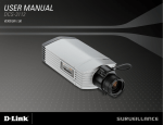
1
Table of Contents
Table of Contents
Product Overview......................................................... 4
Package Contents.................................................... 4
System Requirements.............................................. 4
Introduction............................................................... 5
Features................................................................... 5
Hardware Overview.................................................. 6
Front................................................................... 6
Rear.................................................................... 7
Hardware Installation................................................ 8
Initial Configuration.................................................... 11
Setup Wizard.......................................................... 11
Connect to Your Video Encoder............................. 13
Web-based Configuration Utility............................... 14
Live Video................................................................... 16
Setup............................................................................ 17
Wizard.................................................................... 17
Internet Connection Setup Wizard.......................... 17
Motion Detection Setup Wizard.............................. 20
Network Setup........................................................ 22
Dynamic DNS......................................................... 24
Image Setup........................................................... 25
Audio and Video..................................................... 26
Motion Detection..................................................... 27
Time and Date........................................................ 28
D-Link DVS-310-1 User Manual
Event Setup............................................................ 29
Application........................................................ 30
Add Server........................................................ 31
Add Media......................................................... 32
Add Event......................................................... 35
Add Recording.................................................. 37
SD Card.................................................................. 38
Advanced.................................................................... 39
Digital Input/Output................................................. 39
RS-485................................................................... 40
HTTPS.................................................................... 41
Access List............................................................. 42
Maintenance................................................................ 43
Admin..................................................................... 43
Backup and Restore............................................... 44
Firmware Upgrade.................................................. 45
Status.......................................................................... 46
Device Info.............................................................. 46
Logs........................................................................ 47
Help........................................................................ 48
Using & Configuring the DVS-310-1....................... 49
Router Set-Up and Installation............................... 52
Troubleshooting......................................................... 55
2
Table of Contents
Example DI/DO Schematic......................................... 56
Networking Basics..................................................... 57
Check your IP address........................................... 57
Statically Assign an IP address.............................. 58
Technical Specifications........................................... 59
D-Link DVS-310-1 User Manual
3
Section 1 - Product Overview
Product Overview
Package
Contents
DVS-310-1 Video Encoder
Manual and Software on CD
CAT5 Ethernet Cable
Warranty and GPL Licence
12V 1.25A Power Adapter
Mounting Bracket
and Screws
Quick Installation Guide
Note: Using a power supply with a different voltage will
cause damage and void the warranty for this product.
If any of the above items are missing, please contact your reseller.
System Requirements
• Pentium 4 - 2.4GHz or higher with 512MB RAM
• Windows Vista / Windows XP with SP2 or higher / Windows 2000 with SP4 or higher
• Microsoft IE 6.0 or higher
D-Link DVS-310-1 User Manual
4
Section 1 - Product Overview
Introduction
Congratulations on your purchase of the DVS-310-1 Video Encoder. The DVS-310-1 is a versatile solution that allows
you to make the most of your existing analog surveillance infrastructure. The DVS-310-1 is a standalone system with a
built-in video encoder that converts an analog camera into a full-featured IP-based system. The DVS-310-1 can be remotely accessed
and controlled using a Web browser over an Intranet or the Internet.
Features
Digitally Transform Existing Hardware
The DVS-310-1 Video Encoder makes it possible to integrate a pre-existing analog surveillance infrastructure into a fully-functional IP
surveillance system. The DVS-310-1 is an ideal choice for banks, airports, factories, government buildings, prisons, and traffic surveillance
applications - any location where surveillance equipment is already installed and functioning.
Manage, Record, and View Video with Ease
The hardware encoder supports H.264 / MPEG-4 / MJPEG video with frame rates of up to 30fps at D1 resolution. E-mail notifications help
to keep you up to date whenever a video event occurs. Event recordings can be stored directly to an SD card, or saved to an FTP server.
Simplify Surveillance with Advanced Alarms and Events
Alarm handling features provide alerts in the event of loss of video or loss of network connection. Motion alarms with configurable detection
areas allow for effective surveillance and help to mitigate the need for constant human supervision. A buffer system allows the server to
capture images to the built-in SD card slot before and after an event occurs.
D-Link DVS-310-1 User Manual
5
Section 3 - Configuration
Hardware Overview
Front
LAN Port
Power Socket
SD Card Slot
Power Socket:
Connect the supplied DC adapter here to power the device.
LAN Port:
The 10/100 Ethernet LAN port connects the Video Encoder to networking equipment such as a router or switch.
SD Card Slot:
This slot supports SD cards (standard and SDHC) for removable storage of video and still images.
D-Link DVS-310-1 User Manual
6
Section 3 - Configuration
Rear
DI/DO Ports
Status LED
Audio Out
Reset
Audio In
Video In
Audio In:
This standard 3.5mm stereo jack accepts a connection from a microphone or any suitable analog audio input source.
Audio Out:
This standard 3.5mm stereo jack accepts a connection from a speaker or any suitable analog audio output device.
Video In:
This standard BNC analog video connector accepts a connection from any suitable analog video device. An adapter may be required
when using some types of video cables.
DI/DO Ports:
This pin block includes two sets of digital input connector pairs, one digital output pair, and one RS-485 pair for PTZ control.
Reset Button:
This button can be used to restore the factory default settings. To reset the device to factory defaults, use an unfolded paperclip to press and
hold the button for at least 15 seconds until the power LED stops blinking. The device will reboot automatically after it has been reset.
Status LED:
When solidly lit, this LED indicates that the the device is initializing. When blinking, this LED indicates that the device has acquired an IP
address.
D-Link DVS-310-1 User Manual
7
Section 3 - Configuration
Hardware Installation
Note: The following installation instructions assume that an analog video camera is installed and providing a signal. If necessary, please
consult your camera manufacturer’s user manual for information on how to set up your analog camera.
Connect the Video Cable
Connect the video cable from the camera to the VIDEO IN port
of the Video Encoder.
Once the cable has been connected, rotate the BNC connector
clockwise so that the cable locks into place.
Connect the Power Supply
Attach the external power supply to the DC power socket (labeled
12V 1.25A) and plug the two-pronged adapter into an AC power
outlet. Alternatively, the DVS-310-1 may be powered via PoE
Ethernet cable.In this case, the supplied power adapter should
not be connected.
When the DVS-310-1 is receiving power, the green power
LED will be lit.
D-Link DVS-310-1 User Manual
8
Section 3 - Configuration
Connect the Ethernet Cable
Connect a CAT5 Ethernet cable to the LAN port of the Video
Encoder. Connect the opposite end of the CAT5 cable to an
active network device such as a hub, switch, or router.
Insert an SD Card (Optional)
Insert an SD card with the gold contacts of the card facing
upwards. Push the card into the slot until you feel it click into
place.
Connect Additional Peripheral Devices (Optional)
If desired, you may also connect audio equipment such as a
microphone or speaker to the AUDIO IN and AUDIO OUT ports
respectively. DI/DO devices and PTZ controls may also be
connected.
D-Link DVS-310-1 User Manual
9
Section 3 - Configuration
Mounting Bracket Installation (Optional)
Remove the four rubber feet from the bottom of the device, then affix the mounting brackets as shown below. Secure both of the brackets
into place using the supplied screws.
The brackets may now be used to mount the device on a wall or another flat surface using bolts or screws.
D-Link DVS-310-1 User Manual
10
Section 3 - Configuration
Initial Configuration
This section will show you how to configure your new DVS-310-1 Video Encoder using the D-Link Setup Wizard SE.
Setup Wizard
After loading the Setup Wizard, your Video Encoder’s IP Address will be displayed along with its corresponding MAC Address here.
Your Video Encoder’s IP Address
will be displayed here along with its
corresponding MAC Address.
Click Wizard
D-Link DVS-310-1 User Manual
11
Section 3 - Configuration
Enter the Admin ID and Password.
Note: The default Admin ID is admin with the password left blank.
Click Next
Select DHCP if you want to obtain a new IP address every time the Video Encoder boots up, or
select Static IP to use the same IP address at each boot up.
Click Next
D-Link DVS-310-1 User Manual
12
Section 3 - Configuration
Connect to Your Video Encoder
Setup is now complete.
Click Link to launch the web page of your Video Encoder, to view live
video from your Video Encoder.
Click Link
The Setup Wizard will automatically open your web browser to the IP address of the DVS-310-1.
In this example it is: http://192.168.1.169. Your DVS-310-1 may have a different IP Address.
Enter admin as the default User name and leave the Password blank. Click OK to continue.
You may also use the Internet Explorer web browser to access your Video Encoder’s Home screen
by typing “http://address” in the address box, where address is the IP address that you have
assigned to your Video Encoder in the previous section.
When you connect to the home page of your Video Encoder for the first time, you will be prompted
to download ActiveX. Please follow the prompts to install the ActiveX controls.
D-Link DVS-310-1 User Manual
13
Configuration
Web-based Configuration Utility
This section explains how to configure your new D-Link Video Encoder using the Web-based Configuration Utility.
Click on the D-Link Setup Wizard SE icon that was created in your Windows Start
menu.
Start > D-Link > Setup Wizard SE
Select the Video Encoder and click the button labeled "Link" to access the web
configuration.
The Setup Wizard will automatically open your web browser to the IP address of
the Video Encoder.
Alternatively, you may manually open a browser and enter the IP address of the
Video Encoder: 192.168.0.20
D-Link DVS-310-1 User Manual
14
Enter admin as the default username and leave the password blank. Click OK to
continue.
This section shows your Video Encoder’s live video. You can select your video
profile and view or operate the Video Encoder. For additional information about
web configuration, please refer to the user manual included on the CD-ROM or the
D-Link website.
D-Link DVS-310-1 User Manual
15
Live Video
This section shows your camera’s live video. You may select any of the available icons listed below to operate the camera. You may also
select your language using the drop-down menu on the left side of the screen.
You can zoom in and out on the live video image using your mouse. Right-click to zoom out or left-click to zoom in on the image.
Digital Input
Indicator
Motion Trigger
Indicator
This indicator will change color when a digital
input signal is detected.
This indicator will change color when a trigger
event occurs.
Recording
Indicator
Note: The video motion feature must be
enabled.
When a recording is in progress, this indicator
will change color.
Video Profile 1
Video Profile 2
Video Profile 3
Full screen mode
Taking a Snapshot
Recording a Video Clip
Set a Storage Folder
Listen/Stop Listening
Zoom
Talk/Stop Talking
Start/Stop Digital Output
D-Link DVS-310-1 User Manual
16
Setup
Wizard
To configure your Video Encoder, click Internet Connection Setup
Wizard. Alternatively, you may click Manual Internet Connection
Setup to manually configure your Video Encoder and skip to page 22.
To quickly configure your Video Encoder’s motion detection settings,
click Motion Detection Setup Wizard. If you want to enter your settings
without running the wizard, click Manual Motion Detection Setup and
skip to page 27.
Internet Connection Setup Wizard
This wizard will guide you through a step-by-step process to configure
your new D-Link Video Encoder and connect the camera to the internet.
Click Next to continue.
Note: Select DHCP if you are unsure of which settings to choose.
Click Next to continue.
D-Link DVS-310-1 User Manual
17
Select Static IP if your Internet Service Provider has provided you with
connection settings, or if you wish to set a static address within your home
network. Enter the correct configuration information and click Next to
continue.
If you are using PPPoE, select Enable PPPoE and enter your user name
and password, otherwise click Next to continue.
If you have a Dynamic DNS account and would like the Video Encoder to
update your IP address automatically, Select Enable DDNS and enter your
host information. Click Next to continue.
Enter a name for your Video Encoder and click Next to continue.
D-Link DVS-310-1 User Manual
18
Configure the correct time to ensure that all events will be triggered
as scheduled. Click Next to continue.
If you have selected DHCP, you will see a summary of your settings,
including the Video Encoder's IP address. Please write down all of this
information as you will need it in order to access your Video Encoder.
Click Apply to save your settings.
D-Link DVS-310-1 User Manual
19
Motion Detection Setup Wizard
This wizard will guide you through a step-by-step process to configure your
Video Encoder's motion detection functions.
Click Next to continue.
Step 1
This step will allow you to enable or disable motion detection, specify the
detection sensitivity, and adjust the Video Encoder’s ability to detect movement.
You may specify whether the camera should capture a snapshot or a video
clip when motion is detected.
Please see the Motion Detection section on page 27 for information about
how to configure motion detection.
Step 2
This step allows you to enable motion detection based on a customized
schedule. Specify the day and hours. You may also choose to always record
motion.
D-Link DVS-310-1 User Manual
20
Step 3
This step allows you to specify how you will receive event notifications
from your Video Encoder. You may choose not to receive notifications, or
to receive notifications via e-mail or FTP.
Please enter the relevant information for your e-mail or FTP account.
Click Next to continue.
Step 4
You have completed the Motion Detection Wizard.
Please verify your settings and click Apply to save them.
Please wait a few moments while the Video Encoder saves your settings
and restarts.
D-Link DVS-310-1 User Manual
21
Network Setup
Use this section to configure the network connections for your Video Encoder. All relevant information must be entered accurately.
LAN Settings: Settings for your local area network.
DHCP: Select this connection if you have a DHCP server running on your
network and would like your Video Encoder to obtain an IP address
automatically.
Static IP You may obtain a static or fixed IP address and other network
Address: information from your network administrator for your Video Encoder.
A static IP address may simplify access to your Video Encoder in
the future.
IP Address: Enter the fixed IP address in this field.
Subnet Mask: This number is used to determine if the destination is in the same
subnet. The default value is 255.255.255.0.
Default Gateway: The gateway used to forward frames to destinations in a different
subnet. Invalid gateway settings may cause the failure of
transmissions to a different subnet.
Primary DNS: The primary domain name server translates names to IP addresses.
Secondary DNS: The secondary DNS acts as a backup to the primary DNS.
Enable UPnP: Enabling this setting allows your Video Encoder to be configured as
a UPnP device on your network.
Enable UPnP Enabling this setting allows the Video Encoder to add port forwarding entries into the router automatically on a UPnP
Port Forwarding: capable network.
D-Link DVS-310-1 User Manual
22
Enable PPPoE: Enable this setting if your network uses PPPoE.
User Name: The unique name of your account. You may obtain this information
from your ISP.
Password: The password to your account. You may obtain this information
from your ISP.
HTTP Port: The default port number is 80.
Access Name for The default name is video#.mjpg, where # is the number of the
Stream 1~3: stream.
HTTPS Port: You may use a PC with a secure browser to connect to the HTTPS
port of the Video Encoder. The default port number is 443.
RTSP Port: The port number that you use for RTSP streaming to mobile
devices, such as mobile phones or PDAs. The default
port number is 554. You may specify the address of a
particular stream. For instance, live1.sdp can be accessed at
rtsp://x.x.x.x/video1.sdp where the x.x.x.x represents the ip
address of your Video Encoder.
Maximum
Upload/
Download
Bandwidth:
Specifying the maximum download/upload bandwidth for each
socket can be useful when connecting your device to a busy or
heavily loaded network. Entering a value of '0' indicates that the
Video Encoder should not monitor bandwidth. Specifying other
values will limit the Video Encoder's transfer speed to the specified
number of Kilobytes per second.
D-Link DVS-310-1 User Manual
23
Dynamic DNS
DDNS (Dynamic Domain Name Server) will hold a DNS host name and synchronize the public IP address of the modem when it has been
modified. A user name and password are required when using the DDNS service.
Enable DDNS:
Server Address:
Select this checkbox to enable the DDNS function.
Select your Dynamic DNS provider from the pull down menu or
enter the server address manually.
Host Name:
Enter the host name of the DDNS server.
User Name:
Enter your user name or e-mail used to connect to the DDNS.
Password:
Timeout:
Status:
Enter your password used to connect to the DDNS server.
Enter DNS Timeout values.
Indicates the connection status, which is automatically determined
by the system.
D-Link DVS-310-1 User Manual
24
Image Setup
In this section, you may configure the video image settings for your Video Encoder. A preview of the image will be shown in Live Video.
Enable Privacy
Mask:
The Privacy Mask setting allows you to specify up to 3
rectangular areas on the camera's image to be blocked/
excluded from recordings and snapshots.
You may click and drag the mouse cursor over the camera
image to draw a mask area.
Right clicking on the camera image brings up the following
menu options:
Disable All: Disables all mask areas
Enable All: Enables all mask areas
Reset All: Clears all mask areas.
Mirror:
Flip:
Brightness:
Contrast:
Saturation:
Mirrors the images.
Rotates the image 180 degrees.
This setting is used to compensate for backlit scenes. You may choose a value between 0 and 255.
This setting may help to improve the image in some low light conditions. You may choose a value between 0 and 255.
This setting controls the strength of color. You may choose a value between 0 and 255.
D-Link DVS-310-1 User Manual
25
Audio and Video
You may configure 3 video profiles with different settings for your camera. Hence, you may set up different profiles for your computer and
mobile display. In addition, you may also configure the two-way audio settings for your camera.
Mode: You may select H.264, MPEG4 or MJPEG encoding.
Frame Size: This option allows the user to choose the video resolution of the
camera. The options include NTSC: D1 (720x480), CIF (352x240),
QCIF (176x120) and PAL: D1 (720x576), CIF (352x288), QCIF
(176x144).
Maximum Frame A higher frame rate provides smoother motion for video. Lower
Rate: frame rates will result in stuttering.
Video Quality: Select the number of frames to be captured per second. 30fps is
the highest video quality for this device.
Constant Bit This limits the maximal refresh frame rate, which can be combined
Rate: with the “Fixed quality” to optimize the bandwidth utilization and
video quality. To set the bandwidth utilization regardless of the video
quality, choose “Constant bit rate” and select the desired bandwidth.
Fixed Quality: Select the image quality level of the video. You may choose
Standard, Good, or Excellent.
Audio In Off: Select this option to disable Audio In.
Audio In Gain
Level: Select 0 dB for no gain or 20 dB to make the audio louder.
Audio Out Off: Select this option to disable Audio Out.
Audio Out
Volume Level: Choose a level between 1 and 10.
D-Link DVS-310-1 User Manual
26
Motion Detection
Enabling Video Motion will turn on the motion detection feature. You may draw a finite motion area that will be used for monitoring.
Enable Video
Motion: Select this box to enable the motion detection feature.
Sensitivity: Specifies the measurable difference between two sequential
images that would indicate motion. Please enter a value between
0 and 100.
Percentage: Specifies the amount of motion in the window being monitored
that is required to initiate an alert. If this is set to 100%, motion
is detected within the whole window will trigger a snapshot.
Draw Motion Area: Draw the motion detection area by dragging your mouse in the
window (indicated by the red square).
Erase Motion Area: To erase a motion detection area, simply click on the red square
that you wish to remove.
Right clicking on the camera image brings up the following menu
options:
Select All: Draws a motion detection area over the entire
screen.
Clear All: Clears any motion detection areas that have been
drawn.
Restore: Restores the previously specified motion detection
areas.
D-Link DVS-310-1 User Manual
27
Time and Date
This section allows you to automatically or manually configure, update, and maintain the internal system clock for your Video Encoder.
Time Zone: Select your time zone from the drop-down menu.
Enable Daylight Select this to enable Daylight Saving Time.
Saving:
Auto Daylight Select this option to allow your Video Encoder to configure
Saving: the Daylight Saving settings automatically.
Set Date and Selecting this option allows you to configure the Daylight
Time Manually: Saving date and time manually.
Offset: Sets the amount of time to be added or removed when
Daylight Saving is enabled.
Synchronize with Enable this feature to obtain time automatically from an
NTP Server: NTP server.
NTP Server: Network Time Protocol (NTP) synchronizes the DVS-310-1
with an Internet time server. Choose the one that is closest
to your location.
Set the Date and This option allows you to set the time and date manually.
Time Manually:
Copy Your This will synchronize the time information from your PC.
Computer's Time
Settings:
D-Link DVS-310-1 User Manual
28
Event Setup
The Event Setup page includes 4 different sections.
• Event
• Server
• Media
• Recording
1. To add a new item - "event, server or media," click Add.
A screen will appear and allow you to update the fields
accordingly.
2. To delete the selected item from the pull-down menu of
event, server or media, click Delete.
3. Click on the item name to pop up a window for modifying.
Note: You can add up to four events, five servers, and five
media fields.
D-Link DVS-310-1 User Manual
29
Application
In a typical application, when motion is detected, the DVS-310-1 Video Encoder sends images to a FTP server or via e-mail as notifications.
As shown in the illustration below, an event can be triggered by many sources, such as motion detection or external digital input devices.
When an event is triggered, a specified action will be performed. You can configure the Video Encoder to send snapshots or videos to
your e-mail address or FTP site.
Action
Event Condition
ex.
Motion detection,
Periodically, Digital input,
System reboot
Media
(what to send)
ex.
Snapshot, Video Clips
Server
(where to send)
ex.
Email, FTP
To start plotting an event, it is suggested to configure server and media columns first so that the Video Encoder will know what action shall
be performed when a trigger is activated.
D-Link DVS-310-1 User Manual
30
Add Server
Configure up to 5 servers to store media.
Server Name: Enter the unique name of your server.
E-mail: Enter the configuration for the target e-mail server account.
FTP: Enter the configuration for the target FTP server account.
Network Storage: Specify a network storage device. Only one network storage
device is supported.
SD Card: Use the Video Encoder's onboard SD card storage.
D-Link DVS-310-1 User Manual
31
Add Media
There are three types of media, Snapshot, Video Clip and System Log.
Media Name: Enter an unique name for media.
Snapshot: Select this option to enable snapshots.
Source: The stream source: Profile 1, Profile 2 or Profile 3.
Send pre-event The number of pre-event images.
image(s) [0~4]:
Send post-event The number of post-event images.
image(s) [0~7]:
File name prefix: The prefix name will be added on the file name.
Add date and time Check it to add timing information as file name suffix.
suffix to file name:
Video clip: Select this option to enable video clips.
Source: The source of the profile: profile1, profile2, or profile3.
Pre-event recording: The interval of pre-event recording in seconds.
Maximum duration: The maximal recording file duration in seconds.
Maximum file size: The maximal file size would be generated.
File name prefix: The prefix name will be added on the file name of the video clip.
System log: Select this option to save events to the system log.
D-Link DVS-310-1 User Manual
32
Send post-event image (s) [0~7)
Specify to capture the number of images after a trigger is activated. A maximum of seven images can be generated.
For example:
If both the Send pre-event images and Send post-event images are set to four, a total of 9 images are generated after a trigger is activated.
1 pic.
2 pic.
3 pic.
4 pic.
5 pic.
6 pic.
7 pic.
8 pic.
9 pic.
The moment the
trigger is activated.
Add a date and time suffix to the file name
Select this option to add a date and time to the file name suffix.
SNAPSHOTS20080104_100341
File name prefix Date and time suffix
The format is: YYYYMMDD_HHMMSS
Maximum duration
Specify the maximal recording duration in seconds. You can set up to ten seconds.
For example:
If the Pre-event recording is set to five seconds and the Maximum duration is set to ten seconds, the Video Encoder continues to record
D-Link DVS-310-1 User Manual
33
for another four seconds after a trigger is activated.
1 sec.
2 sec.
3 sec.
4 sec.
5 sec.
6 sec.
7 sec.
8 sec.
9 sec.
10 sec.
The moment the
trigger is activated.
File name prefix
Enter the text that will be added at the beginning of the file name.
VIDEOS20080104_100341
File name prefix Date and time suffix
The format is: YYYYMMDD_HHMMSS
D-Link DVS-310-1 User Manual
34
Add Event
Create and schedule up to 3 events with their own settings here.
Event name: Enter a name for the event.
Enable this Select this box to activate this event.
event:
Priority: Set the priority for this event. The event with higher priority
will be executed first.
Delay: Select the delay time before checking the next event. It is
being used for both events of motion detection and digital
input trigger.
Trigger: Specify the input type that triggers the event.
Video Motion Motion is detected during live video monitoring. Select the
Detection: windows that need to be monitored.
Periodic: The event is triggered in specified intervals. The trigger
interval unit is in minutes.
Digital Input: Triggers an event from a digital input device.
System Boot: Triggers an event when the system boots up.
Network Lost: Triggers an event when the network connect is lost.
Video Lost: Triggers an event when the video feed is lost.
Time: Select Always or specify the time interval.
D-Link DVS-310-1 User Manual
35
Trigger D/O: Select this option to trigger the digital output for a specific number of seconds when an event occurs.
Server: Specify the location where the event information should be saved to. This option will not be available for the Network
Lost trigger.
SD: Select this option to record to an SD card that has been inserted into the device.
D-Link DVS-310-1 User Manual
36
Add Recording
Here you can configure and schedule the recording settings.
Recording entry The unique name of the entry.
name:
Enable this Select this to enable the recording function.
recording:
Set the priority for this entry. The entry with a higher priority
Priority: value will be executed first.
Source: The source of the stream.
Recording Scheduling the recording entry.
schedule:
Recording Configuring the setting for the recording.
settings:
Destination: Select the folder where the recording file will be stored.
Total cycling Please input a HDD volume between 1MB and 200GB for recording space. The recording data will replace the oldest
recording size: record when the total recording size exceeds this value. For example, if each recording file is 6MB, and the total cyclic
recording size is 600MB, then the Video Encoder will record 100 files in the specified location (folder) and then will
delete the oldest file and create new file for cyclic recording.
Please note that if the free HDD space is not enough, the recording will stop. Before you set up this option please
make sure your HDD has enough space, and it is better to not save other files in the same folder as recording files.
Size of each file File size for each recording file. You may input the value in the range of 200-5000.
for recording:
File Name Prefix: The prefix name will be added on the file name of the recording file(s).
D-Link DVS-310-1 User Manual
37
SD Card
Here you may browse and manage the recorded files which are stored on the SD card.
Format SD Card: Click this icon to automatically format the SD card and create
"picture" & "video" folders.
View Recorded If the picture files are stored on the SD card, click on the picture
Picture: folder and choose the picture file you would like to view.
Playback If video files are stored on the SD card, click on the video folder
Recorded Video: and choose the video file you would like to view.
Refresh: Reloads the file and folder information from the SD card.
D-Link DVS-310-1 User Manual
38
Advanced
Digital Input/Output
This screen allows you to control the behavior of digital input and digital output devices. The I/O connector provides the physical interface
for digital output (DO) and digital input (DI) that is used for connecting a diversity of external alarm devices such as IR-Sensors and alarm
relays. The digital input is used for connecting external alarm devices and once triggered images will be taken and e-mailed.
Select D/I or D/O The Video Encoder will send a signal when an event is triggered,
Mode: depending upon the type of device connected to the DI circuit.
N.C. stands for Normally Closed. This means that the normal
state of the circuit is closed. Therefore events are triggered when
the device status changes to "Open."
N.O. stands for Normally Open. This means that the normal state
of the circuit is open. Therefore events are triggered when the
device status changes to "Closed."
LED: You may specify whether or not to illuminate the LED on the side
of the Video Encoder.
D/I and D/O
Pin Block
D-Link DVS-310-1 User Manual
39
RS-485
You may configure the RS-485 settings or communication specifications (baud rate, data bit, stop bit, and parity bit) for your Video
Encoder. RS-485 is a serial communication method for computers and devices. RS-485 is used to control a PAN/TILT apparatus, such
as an external camera enclosure.
Support PAN- When Support PAN-TILT is enabled, a control panel will be
TILT: displayed on the Live Video page allowing control through
RS-485 for an external camera enclosure.
Protocol: Select one protocol type from the pull-down menu.
ID: This ID is the identifier for RS-485 devices. IDs range from
1 to 255.
Baud Rate: Baud Rate is a speed measurement for communication
between a transmitter and receiver which indicates the
number of bit transfers per second. A higher baud rate will
reduce the distance of the two devices (transmitter and
receiver). Values range from 2400 (default) to 19200 bps.
Data Bit: This value is the number of data bits in a transmission. The data bit can be 7 or
8 (default).
RS-485
Pin Block
Parity Bit: Parity is a form of error checking used in serial communication. For even and
odd parities, the serial port sets the parity bit (the last bit after the data bits) to a
value to ensure that the transmission has an even or odd number of logic-high
bits. For example, if the data is 011, for even parity, the parity bit is 0 to keep the
number of logic-high bits even. If the parity is odd, the parity bit is 1, resulting in
3 logic-high bits. Parity can be set to No (none), Even, and Odd.
Stop Bit: The stop bit is used to signal the end of communication for a single packet. The
more bits used for stop bits, the greater the lenience in synchronizing the different
clocks but the slower the data transmission rate. The stop bit can be set to 1 or
2. The default value is 1.
D-Link DVS-310-1 User Manual
40
HTTPS
This page allows you to install and activate an HTTPS certificate for secure access to your Video Encoder.
Enable HTTPS
Secure
Connection: Enable the HTTPS service.
Create Certificate Choose the way the certificate should be created. Three
Method: options are available:
Create a self-signed certificate automatically
Create a self-signed certificate manually
Create a certificate request and install
Status: Displays the status of the certificate.
Note: The certificate cannot be removed while the HTTPS is still
enabled. To remove the certificate you must first uncheck
Enable HTTPS secure connection.
D-Link DVS-310-1 User Manual
41
Access List
Here you can set access permissions for users to view your DVS-310-1.
Allow list: The list of IP addresses that have the access right to the
Video Encoder.
Start IP address: The starting IP Address of the devices (such as a computer)
that have permission to access the video of the camera.
Click Add to save the changes made.
Note: A total of seven lists can be configured for both
columns.
End IP address: The ending IP Address of the devices (such as a computer)
that have permission to access the video of the camera.
Delete allow list: Remove the customized setting from the Allow List.
Deny list: The list of IP addresses that have no access right to the
Video Encoder.
Delete deny list: Remove the customized setting from the Delete List.
For example:
When the range of the Allowed List is set from 1.1.1.0 to 192.255.255.255 and the range of the Denied List is set
from 1.1.1.0 to 170.255.255.255. Only users with IPs located between
171.0.0.0 and 192.255.255.255 can access the Video Encoder.
Alowed
List
D-Link DVS-310-1 User Manual
Denied
List
42
Maintenance
Admin
You may modify the name and administrator’s password of your Video Encoder, as well as add and manage the user accounts for accessing
the Video Encoder. You may also use this section to create the unique name and configure the OSD settings.
Admin Password
Setting: Set a new password for the administrator’s account.
Add User
Account: Add new user account.
User Name: The user name for the new account.
Password: The password for the new account.
User List: All the existing user accounts will be displayed here. You
may delete accounts includes in the list, but please reserve
at least one as guest.
Video Encoder Create a unique name for your Video Encoder that will be
Name: added to the file name prefix when creating a snapshot or
a video clip.
Enable OSD: Select this option to enable the On-Screen Display feature
for your video feed.
Label: Enter a label for the Video Encoder. This label will appear on the video feed.
Show Time: Select this option to enable the time-stamp display on the video feed.
D-Link DVS-310-1 User Manual
43
Backup and Restore
In this section, you may backup, restore and reset the Video Encoder configuration, or reboot the device.
Save To Local You may save and document your current settings into your
Hard Drive: computer.
Locate a pre-saved configuration by clicking Browse and
Local From Local then restore the pre-defined settings to your Video Encoder
Hard Drive: by clicking Load Configuration.
Restore to You may reset your Video Encoder and restore the factory
Factory Default: settings by clicking Restore Factory Defaults.
Reboot Device: This will restart your Video Encoder.
D-Link DVS-310-1 User Manual
44
Firmware Upgrade
The Video Encoder's current firmware version will be displayed on this screen. You may visit the D-Link Support Website to check for the
latest available firmware version.
To upgrade the firmware on your DVS-310-1, please download and save the latest firmware version from the D-Link Support Page to
your local hard drive. Locate the file on your local hard drive by clicking the Browse button. Select the file and click the Upload button to
start upgrading the firmware.
Current Firmware
Version: Displays the detected firmware version.
Current Product
Name: Displays the Video Encoder model name.
File Path: Locate the file (upgraded firmware) on your hard drive by
clicking Browse.
Upload: Uploads the new firmware to your Video Encoder.
D-Link DVS-310-1 User Manual
45
Status
Device Info
This page displays detailed information about your device and network connection.
D-Link DVS-310-1 User Manual
46
Logs
This page displays the log information of your Video Encoder. You may download the information by clicking Download. You may also
click Clear to delete the saved log information.
D-Link DVS-310-1 User Manual
47
Help
This page provides helpful information regarding Video Encoder operation.
D-Link DVS-310-1 User Manual
48
Section 4 - Security
Using & Configuring the DVS-310-1
D-Link’s DVS-310-1 is a versatile and cost-effective Video Encoder offering both video and audio monitoring. It can
also serve as a powerful surveillance system for security applications. This section explains how to view the Video
Encoder from either the Internet or from inside your internal network.
Materials Needed:
• 1 DVS-310-1 Video Encoder
• 1 Ethernet Cable
• A Wired or Wireless Router
• Ethernet based PC for system configuration
Setting Up the DVS-310-1 For Use Behind a Router
Installing a DVS-310-1 Video Encoder on your network is an easy 4-step procedure:
1. Assign a Local IP Address to Your Video Encoder
2. View the Video Encoder Using Your Internet Explorer Web Browser
3. Access the Router with Your Web Browser
4. Open Virtual Server Ports to Enable Remote Image Viewing
This section is designed to walk you through the setup process of installing your Video Encoder behind a router and
enabling remote video viewing. For the basic setup of the DVS-310-1, follow the steps outlined in the Quick Installation
Guide.
D-Link DVS-310-1 User Manual
49
Section 4 - Security
After you have completed the setup of the DVS-310-1 outlined in the Quick Installation Guide you will have an
operating Video Encoder that has an assigned IP Address. When you use a router to share the Internet with
one or more PCs, the IP Address assigned to the Video Encoder will be a local IP Address. This allows viewing
within your Local Area Network (LAN). Later, the router can eventually be configured to allow remote viewing
of video over the Internet.
1. Assign a Local IP Address to Your Video Encoder
Run the Setup Wizard program from the CD included with the DVS-310-1. Follow the steps in the Quick Installation
Guide to configure the DVS-310-1. The Video Encoder will be assigned a local IP Address that allows it to be
recognized by the router. Write down this IP Address for future reference.
This is the IP Address assigned to your Video Encoder (192.168.0.120 is only an example). You will probably have a
different IP Address.
D-Link DVS-310-1 User Manual
50
Section 4 - Security
2. View the Video Encoder Using Your Internet Explorer Web Browser
Run your Internet Explorer Web browser. In the address bar, type in the IP Address that was assigned to the Video
Encoder by the Installation Wizard program. The DVS-310-1 Home Page appears with a window displaying live video
from the Video Encoder. You are able to view this screen from any PC running Internet Explorer on your LAN.
Click on the Configuration button on the left side of the display. Scroll to the bottom of the Network Configuration page
to display the ports used by HTTP and Streaming audio and video.
D-Link DVS-310-1 User Manual
51
Section 4 - Security
Router Set-Up and Installation
3. Access the Router with Your Web Browser
The following steps generally apply to any router that you have on your network. A D-Link Router is used as an example
to clarify the configuration process. Configure the initial settings of the router by following the steps outlined in your
own router’s installation guide.
If you have cable or DSL Internet service, you will most likely have a dynamically assigned WAN IP Address. ‘Dynamic’
means that your router’s WAN IP address can change from time to time depending on your ISP. A dynamic WAN IP
Address identifies your router on the public network and allows it to access the Internet. To find out what your router’s
WAN IP Address is, go to the Status menu on your router and locate the WAN information for your router (as shown
in the screenshot on the right). The WAN IP Address
will be listed. This will be the address that you will need
to type in your Web browser to view your video feed
over the Internet.
Your WAN IP Address will be listed on the router’s
Status > Device Info page.
D-Link DVS-310-1 User Manual
52
Section 4 - Security
Note: Because a dynamic WAN IP can change from time to time depending on your ISP, you may want to obtain a
Static IP address from your ISP. A Static IP address is a fixed IP address that will not change over time and will be
more convenient for you to use to access your Video Encoder from a remote location. The Static IP Address will also
allow you to access your Video Encoder attached to your router over the Internet.
4. Open Server Ports to Enable Remote Image Viewing
The firewall security features built into the router prevent users from accessing the video from the DVS-310-1 over the
Internet. The router connects to the Internet over a series of numbered ports. The ports normally used by the DVS310-1 are blocked from access over the Internet. Therefore, these ports need to be made accessible over the Internet.
This is accomplished using the Port Forwarding function on the router. The ports used by the Video Encoder must be
opened through the router for remote access to your Video Encoder. Port Forwarding is accessed by clicking on the
Advanced tab of the router screen.
Follow these steps to configure your router’s Port Forwarding settings:
1. Click on one of the empty checkboxes.
2. Enter a unique name for the new entry.
3. Enter your Video Encoder’s local IP Address (e.g.,
192.168.1.169) in the IP Address field.
4. If you are using the default port settings, enter 80 into the Start
and End field. Click Save Settings.
5. Select both TCP and UDP for the traffic type.
6. For some routers, Scheduling should be set to Always so
that the camera images can be accessed at any time.
D-Link DVS-310-1 User Manual
53
Section 4 - Security
Please make sure to check the box next to the camera name on the Port Forwarding List to enable your settings.
Important: Some ISPs block access to port 80 and other commonly used Internet ports to conserve bandwidth. Check
with your ISP so that you can open the appropriate ports accordingly. If your ISP does not pass traffic on port 80, you
will need to change the port from 80 to something else, such as 800. Not all routers are the same, so refer to your user
manual for specific instructions on how to open ports.
D-Link DVS-310-1 User Manual
54
Section 5 - Troubleshooting
Troubleshooting
1. Why is the Power LED not lighting up?
The power supply used might be at fault. Confirm that you are using the provided power supply, which is DC 12V, for
the Video Encoder. Also verify that the power supply is securely connected. If the device is functioning but the LED
is not illuminated, the LED may be disabled. Open the firewall configuration page and click MAINTENANCE. At the
bottom of the page, there will be an option to turn on or turn off the LED.
2. Why does the Video Encoder work locally but not remotely?
This might be caused by firewall protection. Check with your system administrator to see if you are behind a firewall.
The firewall may need to have some settings changed in order for the Video Encoder to be accessible outside your LAN.
Make sure that the Video Encoder is not conflicting with any Web server you may have running on your network.
The default router setting might be another possible reason. Check that the configuration of your router’s settings allow
the Video Encoder to be accessed outside your local LAN.
3. Why are no images available through the Web browser?
ActiveX controls might be disabled within Internet Explorer. Check that ActiveX has been enabled in the Internet
Options menu. You may also need to change the security settings on your browser to allow the ActiveX plug-in to be
installed. If you are using a version of Internet Explorer before version 6.0, you will need to upgrade Internet Explorer
in order to view the streaming video transmitted by the Video Encoder.
D-Link DVS-310-1 User Manual
55
Section 5 - Troubleshooting
Example DI/DO Schematic
DI
Receives signals from a reed switch, vibration sensor,
or any other external security device.
DO
Connects to an alarm or buzzer.
485+/485-
D-Link DVS-310-1 User Manual
Connects to an RS-485 interface for controlling
auxiliary equipment such as an external camera
enclosure for pan, tilt, and zoom functionality.
56
Appendix B - Networking Basics
Networking Basics
Check your IP address
After you install your new D-Link adapter, by default, the TCP/IP settings should be set to obtain an IP address from
a DHCP server (i.e. wireless router) automatically. To verify your IP address, please follow the steps below.
Click on Start > Run. In the run box type cmd and click OK.
At the prompt, type ipconfig and press Enter.
This will display the IP address, subnet mask, and
the default gateway of your adapter.
If the address is 0.0.0.0, check your adapter
installation, security settings, and the settings
on your router. Some firewall software programs
may block a DHCP request on newly installed
adapters.
If you are connecting to a wireless network at a
hotspot (e.g. hotel, coffee shop, airport), please contact an employee or administrator to verify their wireless network
settings.
D-Link DVS-310-1 User Manual
57
Appendix B - Networking Basics
Statically Assign an IP address
If you are not using a DHCP capable gateway/router, or you need to assign a static IP address, please follow the steps
below:
Step 1
Windows® Vista - Click on Start > Control Panel > Network and Internet > Network and Sharing Center > Manage
Network Connections.
Windows XP - Click on Start > Control Panel > Network Connections.
Step 2
Right-click on the Local Area Connection which represents your D-Link network adapter and select Properties.
Step 3
Highlight Internet Protocol (TCP/IP) and click Properties.
Step 4
Click Use the following IP address and enter an IP address that is on the same
subnet as your network or the LAN IP address on your router.
Example: If the router’s LAN IP address is 192.168.0.1, make your IP address
192.168.0.X where X is a number between 2 and 99. Make sure that the number
you choose is not in use on the network. Set Default Gateway the same as the LAN
IP address of your router (192.168.0.1).
Set Primary DNS the same as the LAN IP address of your router (192.168.0.1). The
Secondary DNS is not needed or you may enter a DNS server from your ISP.
Step 5
Click OK twice to save your settings.
D-Link DVS-310-1 User Manual
58
Appendix C - Technical Specifications
Technical Specifications
Hardware Specifications
• Power Supply: DC 12V / 1.25A
• Removable Storage: SD Card Slot (SDHC compliant)
Video Specifications
Codec
• Simultaneous multi profile support ( H.264, MPEG4 and MJPEG)
• Support 3GPP for mobile phone
• JPEG compression for still images
Resolution
• NTSC: D1 (720x480), CIF (352x240),
QCIF (176x120)
• PAL: D1 (720x576), CIF (352x288),
QCIF (176x144)
Input
• 1CH, NTSC/PAL, BNC connector
• 1.0Vp-p with 75 Ω loading,
Audio Specifications
• Two-way audio
• External audio in
• External audio out
• G.726 codec
Networking Specifications
• Ethernet: RJ45 - 10/100 Base-TX
• Supported Protocols: IPv4, DHCP, ARP, DNS, TCP/IP, DDNS
(D-Link), HTTP, HTTPS, UPnP™ Port Forwarding, Samba, SMTP,
PPPoE, NTP (D-Link), FTP, RTP, RTSP, UDP, RTCP, ICMP, 3GPP
Minimum System Requirements
•CPU: Pentium 4, 2.4GHz and above
•Hard Disk: 40 GB or higher
•Memory: 512 MB or higher
•Operating System: Windows 7 / Vista /
Windows XP with SP2 or higher /
Windows 2000 with SP4 or higher
•Video Resolution: 1024x768 (SVGA/XGA)
•Software: DirectX 9.0c or higher
•Browser: Microsoft IE 6.0 or higher
Power Input
• 802.3af (PoE)
• 100 ~240VAC, 50/60Hz, 12V DC 1.25A
Dimensions
•105.1(L) x 78.3 (W) x 35.7 (H) mm
Operating Temperature
•0° to 40°C (32° to 104°F)
Operating Humidity
•20% to 80% non-condensing
Certifications
•CE (Class A)
•C-Tick (Class A)
•FCC (Class A)
PTZ Specifications
• Baud rates: 2400, 4800, 9600, 19200
• Connector: RS-485 for PTZ control
D-Link DVS-310-1 User Manual
59