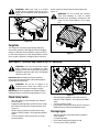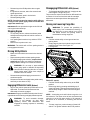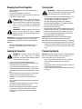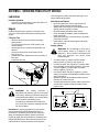
1
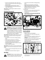
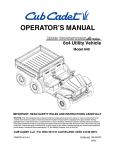
Operator’s Manual
4x2 Utility Vehicle
Model 420A
430A
430D
IMPORTANT: READ SAFETY RULES AND INSTRUCTIONS CAREFULLY
Warning: This unit is equipped with an internal combustion engine and should not be used on or near any unimproved forestcovered, brush-covered or grass-covered land unless the engine’s exhaust system is equipped with a spark arrester meeting
applicable local or state laws (if any). If a spark arrester is used, it should be maintained in effective working order by the operator.
In the State of California the above is required by law (Section 4442 of the California Public Resources Code). Other states may have
similar laws. Federal laws apply on federal lands. A spark arrester for the muffler is available through your nearest engine authorized
service dealer or contact the service department.
CUB CADET LLC P.O. BOX 361131 CLEVELAND, OHIO 44136-0019
PRINTED IN U.S.A.
FORM NO. 769-00665.fm
(2/03)
TABLE OF CONTENTS
Content
Page
Important Safe Operation Practices................................................................... 3
Know Your Utility Vehicle ................................................................................... 7
Operating Your Utility Vehicle ............................................................................ 10
Servicing Your Utility Vehicle ............................................................................. 13
Service Chart ..................................................................................................... 16
Accessories ....................................................................................................... 17
Specifications .................................................................................................... 17
Troubleshooting ................................................................................................. 18
FINDING MODEL NUMBER
This Operator’s Manual is an important part of your new utility vehicle. It will help you assemble, prepare
and maintain the unit for best performance. Please read and understand what it says.
Before you use your new utility vehicle, please locate the model plate on the vehicle
under the left side of dash panel and copy the information from it in the space provided
below. The information on the model plate is very important if you need help from our
Customer Support Department or an authorized center.
•
A sample model plate is explained below. For future reference, please copy the model number and
the serial number of the equipment in the space below.
Copy the model number here:
Copy the serial number here:
CUB CADET LLC
P. O. BOX 361131
www.cubcadet.com CLEVELAND, OH 44136
DEALER LOCATOR PHONE NUMBER: 877-282-8684
CALLING CUSTOMER SUPPORT
If you have difficulty assembling this product or have any questions regarding the controls,
operation or maintenance of this unit, please call the Customer Dealer Referral Line, 1-877282-8684. Please have your unit’s model number and serial number ready when you call.
See previous section to locate this information. You may be asked to enter the serial number
in order to process your call.
For more details about your unit, visit our website at www.cubcadet.com
2
SECTION 1: IMPORTANT SAFE OPERATION PRACTICES
WARNING: This symbol points out important safety instructions which, if not followed, could endanger
the personal safety and/or property of yourself and others. Read and follow all instructions in this
manual before attempting to operate or service this vehicle. When you see this symbol - heed its
warning.
WARNING: Engine exhaust, some of its constituents, and certain vehicle components contain
or emit chemicals known to the State of California to cause cancer and birth defects or other
reproductive harm.
DANGER: This vehicle is designed to be operated according to the rules for safe operation in
this manual. As with any type of vehicle, carelessness or error on the part of the operator can
result in serious injury. Failure to observe the following safety instructions could result in
serious injury or death.
General Operation
13. Sit on the center of the seat and keep both feet
within the foot platform perimeter. Clean foot
platform if dirty and remove any debris from around
foot controls, e.g. brake pedal.
14. Do not misuse the utility vehicle. It is an utility
vehicle, not a recreation vehicle or toy.
Recreational riding can lead to accidents, severe
bodily injury or death.
15. Inspect area around vehicle before moving, especially in reverse. Back up slowly. Always look down
and behind before and while backing to avoid a
back-over accident. Keep bystanders out of area.
16. Avoid driving through water, since loss of control
may occur. Drive belt may slip if exposed to water
thus reducing vehicle pulling power and stopping
vehicle entirely.
17. Always use vehicle lights while operating in low
light situations.
18. Do not mount or leave vehicle while it is in motion or
in actual operation.
19. Avoid sudden starts, stops, or turns and always use
a level turn-around area.
20. Never leave vehicle unattended with the key in the
ignition. Always turn key to the “Stop” position, set
the parking brake and remove key.
21. Check overhead clearances carefully before driving
under low hanging tree branches, wires, etc.,
where the operator may be struck or pulled from the
unit, which could result in serious injury.
22. Improper use of the vehicle or failure to properly
maintain it could result in decreased vehicle
performance or personal injury.
23. Engine must be stopped when cleaning, servicing,
adjusting, repairing, or installing attachments on
utility vehicle.
24. After striking foreign objects, stop the unit and shut
off the engine. Inspect for damage and repair the
damage before restarting and operating
equipment.
1. Read, understand, and follow all instructions on the
vehicle and in the manual before attempting to
operate or service. Keep this manual in a safe
place for future and regular reference and for
ordering replacement parts.
2. This is an off-road utility vehicle and it should not be
operated on public highways. Know and comply
with all laws and regulations governing the use of
off-highway vehicles in your area.
3. This vehicle handles and maneuvers differently
than a normal passenger car. Sharp high speed
turns and abrupt maneuvers can cause vehicle to
roll over or go out of control. Slow down when
turning and avoid abrupt maneuvers.
4. Handling and maneuvering characteristics of
vehicle change depending upon cargo load. Heavy
loads affect steering, braking, stability, and overall
handling of vehicle.
5. Be familiar with all instructions and controls and
their proper operation before starting vehicle.
6. Never allow adults to operate this vehicle without
proper instruction.
7. Never allow children under 16 years old to operate
this vehicle. Children 16 years old and over should
read and understand the operation instructions and
safety rules in this manual and should be trained
and supervised by a parent.
8. Watch for traffic when operating near or crossing
roadways. This vehicle is not intended for use on
any public roadway.
9. Do not operate this vehicle while under the
influence of alcohol or drugs.
10. Never carry more than one passenger. This vehicle
is designed to carry the driver and one passenger
only. No riders are allowed in cargo box or
anywhere else on vehicle.
11. Keep all body parts (i.e. head, arms, hands, legs,
feet) inside vehicle when vehicle is in motion.
12. Always remain seated and keep both hands on the
steering wheel when driving the vehicle.
3
Children
25. Do not start or operate vehicle in an inside area,
unless it is adequately ventilated. Engine exhaust
contains carbon monoxide fumes, which are very
poisonous and can be deadly.
26. Do not change engine governor setting or over
speed the engine. The governor is set at the factory
for safe operating speed.
27. Assure safety interlock switch is adjusted correctly
so engine cannot be started unless gearshift is in
the neutral position.
28. Do not touch engine or muffler while engine is
running or soon after it is stopped. They will be hot
and can cause a burn.
29. Always inspect your vehicle each time you use it to
make sure it is in safe operating condition. Always
follow the inspection and maintenance procedures
and schedules described in this manual.
30. If situations occur which are not covered in this
manual, use care and good judgement. Contact
your local service center or call toll free 1-877-2828684 for assistance and the name of your nearest
service center.
1. Tragic accidents can occur if the operator is not
alert to the presence of children. Children are often
attracted to the vehicle. They do not understand the
dangers. Never assume that children will remain
where you last saw them. Avoid run over accidents.
a. Keep children out of the immediate area of
the vehicle and in watchful care of a
responsible adult other than the operator.
b. Be alert and turn the vehicle off if a child
enters the area.
c. Before and while backing, look behind and
down for small children.
d. Never carry children, they may fall off and be
seriously injured or interfere with safe vehicle
operation.
e. Use extreme care while approaching blind
corners, doorways, shrubs, trees or other
objects that may block your vision of a child
who may run into the path of the vehicle.
f. Remove key when vehicle is unattended to
prevent unauthorized operation.
2. Never allow children under 16 years old to operate
this vehicle. Children 16 years old and over should
read and understand the operation instructions and
safety rules in this manual and should be trained
and supervised by a parent.
3. Do not let children ride in the cargo box, in the
driver’s or passenger’s lap or anywhere other than
the passenger seat. Never give small children a
ride; not even in the passenger seat. They may fall
off.
Slope Operation
Slopes are a major factor related to loss of control and
rollover accidents, which can result in severe injury or
death. If a slope is steeper than a 15° incline, do not
operate this unit on that area. Exercise extreme caution
while operating on slopes.
DO:
1. Travel straight up and down slopes, not across.
Exercise extreme caution when changing direction
on slopes.
2. Travel slowly while on a slope. Always keep the
forward speed limited when going down slopes to
take advantage of the motor braking action.
3. Keep all movement on the slopes slow and gradual.
Avoid starting or stopping on a slope.
4. Avoid slopes with slippery, loose, or bumpy
surfaces as they are especially hazardous.
5. Use extra care while carrying cargo. It may affect
the stability of the vehicle. Spread the load evenly
or tie down.
Do Not:
Cargo Box Loading/Operation
1. Do not exceed vehicle’s Total Load Capacity rating
of 1,200 lb. This includes operator, passenger,
accessories, and cargo.
2. Do not exceed 800 lb. load in cargo box.
3. Spread load evenly and secure to prevent
movement.
4. Do not load above height of cargo box front panel.
Load could shift forward and injure driver or
passenger.
5. Avoid loads which exceed the physical dimensions
of cargo box.
6. Go slow. Heavy loads will affect steering, braking,
stability, and overall handling of the vehicle. Limit
loads to those that can be safely controlled.
7. Avoid sudden starts, stops, and turns which could
cause load to shift.
1. Do not travel near drop-offs, ditches or
embankments. The vehicle could suddenly turn
over if a wheel is over the edge of a cliff, ditch, or if
an edge caves in.
2. Do not stop or start suddenly when going uphill or
downhill. Be especially cautious when changing
direction on slopes.
3. Do not turn sideways to the hill. The vehicle may roll
over. If you must turn, go slow and do so carefully
and gradually.
4. Do not carry cargo on steep slopes or tow loads.
Cargo Box Lift
1. Stop vehicle on level ground and set Parking Brake
before raising cargo box.
2. On manual lift units, unload cargo box before
raising cargo box.
4
c. When practical, remove gas-powered
equipment from the truck or trailer and refuel
it on the ground. If this is not possible, then
refuel such equipment on a trailer with a
portable container, rather than from a
gasoline dispenser nozzle.
d. Keep the nozzle in contact with the rim of the
fuel tank or container opening at all times
until fueling is complete. Do not use a nozzle
lock-open device.
e. Extinguish all cigarettes, cigars, pipes and
other sources of ignition.
f. Never fuel machine indoors.
g. Never remove gas cap or add fuel while the
engine is hot or running. Allow engine to cool
at least two minutes before refueling.
h. Never over fill fuel tank. Fill tank to no more
than ½ inch below bottom of filler neck to
allow space for fuel expansion.
i. Replace gasoline cap and tighten securely.
j. If gasoline is spilled, wipe it off the engine
and equipment. Move unit to another area.
Wait 5 minutes before starting the engine.
k. To reduce fire hazards, keep machine free of
grass, leaves, or other debris build-up. Clean
up oil or fuel spillage and remove any fuel
soaked debris.
l. Never store the machine or fuel container
inside where there is an open flame, spark or
pilot light as on a water heater, space heater,
furnace, clothes dryer or other gas
appliances.
3. Do not operate vehicle with cargo box in raised
position.
4. Do not operate vehicle with cargo box latch
unlatched. Always re-latch upon manually lowering
cargo box.
5. When using optional electric lift:
• Stay in driver’s seat.
• Keep body parts away from cargo box and keep all
bystanders away.
• Do not allow rear wheels to hang over the edge of a
drop-off when raising cargo box. Cargo box weight
may shift over center and cause vehicle to tip over
backwards.
Towing
•
•
•
•
•
Always use an approved hitch and hitch point
provided on the utility vehicle.
Do not tow more than 900 lb. (454 kg) rolling weight
(i.e. trailer plus cargo).
Never load more than 100 lb. (45.5 kg) tongue
weight on tow bracket provided.
Go slow and use extra care when towing a trailer.
Allow for increased braking distance. Load trailer
properly.
Do not tow heavy loads on slopes greater than 5°
incline. When going downhill or turning, the extra
weight tends to push the tow vehicle and may
cause you to loose control (i.e. braking and steering
ability are reduced, towed equipment may jackknife and cause utility vehicle to overturn).
Service
WARNING: Your Responsibility: Restrict the
use of this vehicle to persons who read,
understand and follow the warnings and
instructions in this manual and on the unit.
Safe Handling Of Gasoline:
1. To avoid personal injury or property damage use
extreme care in handling gasoline. Gasoline is
extremely flammable and the vapors are explosive.
Serious personal injury can occur when gasoline is
spilled on yourself or your clothes which can ignite.
Wash your skin and change clothes immediately.
a. Use only an approved gasoline container.
b. Never fill containers inside a vehicle or on a
truck or trailer bed with a plastic liner. Always
place containers on the ground away from
your vehicle before filling.
5
WARNING
WARNING
RIDERS CAN FALL OFF AND BE
SERIOUSLY INJURED OR KILLED
• This is an off-road utility vehicle. Do not operate
on public highways. It handles and maneuvers
differently than a normal passenger car. Sharp,
high speed turns or abrupt maneuvers can
cause vehicle to roll over or go out of control.
• Handling and maneuvering characteristics
of vehicle change depending upon cargo load.
Heavy loads will affect steering, braking,
stability and overall handling of vehicle.
• Read and understand operator's manual
before operating vehicle.
• Only one person in each seat.
• No riders in the cargo box or anywhere
other than seats.
MAX 15º
FALLING OFF OR ROLLOVER MAY
CAUSE SERIOUS INJURY OR DEATH
• Only one person in each seat.
• No other riders permitted.
• Keep hands and feet inside vehicle during
operation.
• Do not operate on slopes greater than 15º.
• Drive slowly when turning, on rough ground,
or carrying a cargo load.
• Spread load evenly in cargo box. Do not exceed
load capacity specified on cargo box label.
• Secure load to prevent movement.
WARNING
CARGO BOX LOAD CAPACITY:
MAX 800 Lb.
• Spread load evenly. Secure load to prevent movement.
• Go slow. Avoid sudden starts and stops which could
cause load to shift.
• Do not load above height of this panel. Load could shift
forward injuring driver or passenger.
WARNING
CARGO BOX
LATCH
• Always re-latch
cargo box latch
upon manually
lowering cargo box.
• Do not operate or
load vehicle with
cargo box latch
unlatched.
AVOID INJURY WHEN
USING CARGO BOX LIFT
• Read and understand operator's manual for
lifting, loading and unloading instructions.
• Stop vehicle on level ground and set parking
brake before operating lift.
• Make sure manual lift support rod is securely
locked before leaning under raised cargo box.
• When using optional electric lift stay in seat and
keep hands away from cargo box.
6
• No riders in cargo box
or anywhere other than
seats.
WARNING
To Avoid An Accident And Injury
• Do not tow more than 900 Lb. rolling
weight (i.e., trailer plus cargo).
• Spread load evenly. Never exceed 100 lb.
tongue weight.
• Go slow and use extra care when towing.
Allow for increased braking distance.
• Do not tow heavy loads on slopes over
a 5º incline.
S32162
SECTION 2: KNOW YOUR UTILITY VEHICLE
NOTE: Reference to right or left hand side of the utility vehicle is observed from the operating position.
Figure 1
Brake Pedal
Read this operator’s manual, safety labels, and
operating instructions on the vehicle before operating.
Compare the illustrations in this manual with your unit
to familiarize yourself with the location of various
controls and adjustments. Reference to the right or left
hand side of unit is observed from the operating
position. Save this manual for future reference.
See Figure 1.
Read the Honda Engine operator’s manual before
operating this vehicle to familiarize yourself with the
engine controls and adjustments.
The brake pedal is located on the left side of the floor
beneath the dash panel. Remove foot from accelerator
pedal apply pressure to the brake pedal evenly until
vehicle slows down and stops. See Figure 2.
NOTE: Before operating your vehicle, follow the
starting instructions in the Operating Section and
check tire pressure per the recommendations in the
Maintenance Section.
Accelerator Pedal
Brake Pedal
The accelerator pedal is located on the right side of the
floor beneath the dash panel. Depressing the
accelerator pedal will move the vehicle in the direction
selected on the gearshift. As the pedal is depressed,
speed will increase to the maximum selected range.
Releasing the pedal reduces the speed, but does not
stop the vehicle. The brake must be applied to stop
vehicle. See Figure 2.
Accelerator Pedal
Figure 2
Parking Brake Latch
The parking brake latch is located on the right side of
the dash panel. It holds the brake in the engaged
position for parking. See Figure 3.
7
•
•
12V Power Outlet
To engage the parking brake, push brake pedal
down firmly, pull out on the parking brake latch, and
release foot from brake pedal. Brake pedal will stay
down and parking brake light on dash will come on
to indicate parking brake is engaged.
To release parking brake, push down on brake
pedal and parking brake latch will release.
The 12V power outlet is located on the right side of the
dash panel. It is used for the convenience of plugging in
accessories that require a power source with a
maximum load of 5 amps at 12 volts. See Figure 4.
Accessory Power Switch (Optional)
If equipped, the accessory power switch is located on
the right side of the dash panel. This switch turns power
on or off for optional accessories. See Figure 5.
Parking Brake
Latch
Cargo Box Electric Lift Switch (Optional)
If equipped, the cargo box electric lift switch is located
on the right side of the dash panel. It activates lift to
raise and lower cargo box. See Figure 5.
Rear Power Outlet (Optional)
Figure 3
If equipped, the rear power outlet is located on the right
side of the dash panel. It turns power on and off for the
rear outlet. See Figure 5.
Ignition Switch
WARNING: Never leave a running machine
unattended. Always set parking brake, stop
engine and remove key to prevent unintended
starting.
The ignition switch is located on the right side of the
dash panel. To start the engine, insert the key into the
ignition switch and turn clockwise to the START
position. Release the key into the Run position once
engine has fired. See Figure 4.
Cargo Box Electric
Lift Switch (Optional)
NOTE: The shift controller will return the transmission to
neutral when the key is turned off. If the lever is not in
neutral it must be manually returned to neutral to start
engine. Refer to SECTION 8:Troubleshooting.
Figure 5
Warning Light Cluster
The warning light cluster is located in the middle of the
dash panel. There are four warning lights: alternator discharge light, parking brake light, engine oil pressure
light, and low fuel light. The parking brake light indicates
when parking brake is engaged. The engine oil pressure
light activates when engine has low oil pressure. The
alternator discharge light will indicate that the alternator
is not charging. The low fuel light activates when fuel is
low in tank. See Figure 6.
Horn Plug
Gear Lights
Engine Oil
Pressure Light
12V Power
Outlet
Ignition Switch
Rear Power
Outlet (Optional)
AccessoryPower
Switch (Optional)
Figure 4
Refer to Starting The Engine in the Operation Section of
this manual for detailed starting instructions
Alternator
Discharge Light
R
N
F
R
N
F
HOURS 1/10
Horn Switch (Optional)
Parking
Brake
Light
The horn switch is located on the right side of the dash
panel. Push button to activate horn. See Figure 4.
Hour Meter
Figure 6
8
Low Fuel
Light
Gear Lights
Gearshift Switches
The gear lights are located in the center and at the top
of the warning light cluster. See Figure 6. Once a gear
is selected, the instrument panel will illuminate a gear
light or a combination of gear lights. If the vehicle has
not shifted properly, or there is a shifting issue, the
lights will flash for 5 seconds and an audible tone will
sound. During this time a shift will not be allowed,
however, once the lights stop flashing, shifting will be
allowed. Refer to SECTION 8:Troubleshooting to
determine the failure mode.
NOTE: The gearshift switches are located in the middle
of the dash to the right of the steering column. When
pushing the appropriate switch for forward, neutral, or
reverse, the brake pedal must be depressed. See
Figure 8.
Gearshift
Switches
Hour Meter
R
N
F
R
N
F
HOURS 1/10
The hour meter is located in the center of the warning
light cluster. It reads the elapsed time engine has run.
See Figure 6.
Light Switch
Figure 8
The light switch is located on the left side of the dash
panel. Push in top/bottom of switch to activate or turn
off lights. See Figure 7.
Gas Gauge
The gas gauge is located under the seat on the left
side. It is mounted on top of the gas tank and it
indicates amount of fuel in tank. The fuel tank is 5.7
gallons. See Figure 9.
Choke
The choke lever is located on the left side of the dash
panel. The choke is used when starting a cold engine. It
richens the fuel mixture for cold weather starting.
See Figure 7.
Fuel Shut Off Valve
The fuel shut off valve is located under the seat and it is
strapped onto the fuel tank. It controls fuel to the
engine. To turn fuel off, turn knob so indicator is down.
To turn fuel on, turn knob to the up position.
See Figure 9.
Choke
Light Switch
Fuel Shut
Off Valve
Differential Lock Switch
Gas Gauge
Figure 7
Differential Lock Switch (Optional)
The differential lock switch is located on the left side of
the dash panel. When pushed, the differential switch
locks the differential so both drive wheels will pull
equally when rear wheels start to slip. See Figure 7.
Figure 9
Cup Holders
Adjustable Seat Lever
The cup holders are located between the seats. They
are designed for the use of non-alcoholic beverages.
The adjustable seat lever is located beneath the
driver’s seat on the front side and it is used to move the
seat forward and backward. See Figure 10.
WARNING: Never operate this vehicle while
under the influence of alcohol or drugs. Doing
so can result in serious personal injury or
death.
•
•
9
Slide the lever to the left and push the seat forward
or back to the desired position.
Release the lever so that it locks the seat in place.
lift, the cargo box can be raised to dump cargo. See
Figure 11.
WARNING: Make sure seat is in locked
position prior to operation and do not try to
adjust the seat position while operating the
vehicle.
WARNING: Do not exceed the vehicle’s
Total Load Capacity of 1,200 lb., which
includes driver, passenger, accessories, and
cargo. Do not exceed 800 lb. in the cargo
box.
Cargo Box
Seat Lever
Figure 10
Cargo Box
The cargo box is raised by a gas spring. Manually
remove the contents of the cargo box before lifting the
cargo box. Release the latch and the cargo box will lift
up. Once the cargo box is in the raised position, access
to the engine is possible. If equipped with a electrical
Figure 11
SECTION 3: OPERATING YOUR UTILITY VEHICLE
WARNING: This is an off-road utility vehicle
and it should not be operated on public
highways. Know and comply with all laws and
regulations governing the use of off-highway
vehicles in your area.
IMPORTANT:Before starting the engine read this
manual and the Honda Engine manual thoroughly to
understand all instructions.
WARNING: Do not run an engine in an
enclosed area. Move the vehicle to an
outside area before running the engine.
IMPORTANT:Tires are shipped over-inflated. Reduce
inflation pressure in all tires to approximately 5 -6 psi.
Figure 12
Check Safety Switch
•
•
•
•
•
Sit in the operator’s seat and place key switch in
STOP position.
Engage the parking brake, raise and secure cargo
box, and move lever to the forward position. See
Figure 12.
Sit back down in operator’s seat and move key
switch to START position. The engine should NOT
crank.
Turn key switch to STOP and move lever to the
reverse position.
•
•
Sit back down in operator’s seat and move key
switch to START position. The engine should NOT
crank.
Turn key switch to STOP.
Keep engine compartment clean and be sure fan or
flywheel screens remains installed and clean.
Starting Engine
•
•
•
•
10
Sit in the operator’s seat and place key switch in
STOP position.
Lock parking brake.
Pull out the choke knob if engine is cold.
Turn key to the START position.
•
•
•
•
Disengaging Differential Lock (Optional)
Release key to the RUN position when engine
starts.
If engine does not start, wait a few seconds and
repeat procedures.
After engine starts, push in choke knob.
Release parking brake.
•
To disengage the differential lock, simply push the
button again. The light will go off.
Torque must be equal on both axles for differential lock
to release. It is best to slow down and drive straight
ahead at a constant speed when disengaging the
differential.
NOTE: If engine surges after starting while idling or
driving at a low speed, apply choke as needed until
engine has warmed up.
Raising and Lowering Cargo Box
IMPORTANT:Do not operate the engine under full load
WARNING: To prevent the possibility of
bodily injury from unintentional lowering of
the cargo box, be sure vehicle is on a level
and stable surface and parking brake is
locked before raising cargo box.
until engine has warmed up.
Stopping Engine
•
•
•
To stop utility vehicle, release accelerator pedal
and depress brake pedal until vehicle comes to a
complete stop.
Lock parking brake and turn key switch to STOP
position.
Remove the key when not in use.
Manual Lift
•
•
WARNING: The vehicle will roll if the parking brake is
not engaged and locked.
•
Park the vehicle safely on level ground and set
parking brake.
Empty cargo by hand and unhook cargo box latch
located in front of box. See Figure 13.
Lift cargo box.
Driving Utility Vehicle
•
•
•
Make sure front wheels are turned to the desired
direction.
Depress brake pedal to release parking brake.
To avoid damaging transmission, depress brake
pedal fully and make sure vehicle is completely
stopped before shifting into Forward or Reverse.
WARNING: Do not stop or start suddenly
when going uphill or downhill. Be especially
cautious when changing direction on slopes.
Apply brakes when going down slopes to
maintain control of vehicle.
•
•
Gas Spring
Release brake pedal and apply pressure to the
accelerator pedal.
Release accelerator and apply brake pedal evenly
and firmly to slow down or stop.
Cargo Latch
Figure 13
Electric Lift (Optional)
•
Engaging Differential Lock (Optional)
•
•
Stop or slow vehicle speed and push button to lock
differential. The button will illuminate and the
differential will remain engaged.
IMPORTANT: Engage the differential when the left and
Park the vehicle safely and turn key to the RUN
position.
Raise cargo box by pressing and holding top of
electric lift switch. Release switch when box is at
desired dump height or when maximum height is
reached.
NOTE: A ratcheting noise will indicate cargo box is at
full extension. The same noise will also be heard when
cargo box is at the full down position. If lift capacity of
the power lift is exceeded, a ratcheting will also be
heard.
right side wheels are turning at slightly different speeds.
WARNING: To avoid transaxle damage,
injury, or turf damage, go slow when
operating vehicle with differential lock
engaged as steering response is noticeably
reduced.
•
11
To lower cargo box, push on bottom of electric lift
switch. Turn ignition switch to the STOP position.
Dumping Load From Cargo Box
•
•
•
Towing Loads
Back up the vehicle to the dump site and apply
parking brake.
Unhook the tailgate from cargo box.
If using an electric lift, raise cargo box to dump load
and lower box when empty.
WARNING: To help prevent personal injury
due to loss of control or tipping, always tow a
load slowly enough to maintain control.
•
WARNING: The center of gravity changes as
a loaded cargo box is raised. Do not allow
rear wheel to hang over the edge of a loading
dock or ravine. The cargo box weight may
shift over center and vehicle could tip over
backwards.
•
•
•
WARNING: A loaded cargo box can be very
heavy. Do not attempt to dump a loaded
cargo box unless vehicle is equipped with an
electric lift option.
Do not tow a load that exceeds 900 lbs.(454.5 kg)
rolling weight (i.e. trailer plus cargo) and never
exceed 100lbs (45.5kg) tongue weight.
Go slow when towing a heavy load. Allow for
increased braking distance. Tow load at a speed
slow enough to maintain control.
Do not tow on steep slopes.
Be particularly cautious when towing down even a
gradual slope or turning. The extra weight tends to
push the tow vehicle and may cause you to lose
control (braking and steering ability are reduced;
towed equipment may jack-knife).
if actuator clutch slippage occurs. Lower cargo box
completely and remove excess load by hand before
dumping.
IMPORTANT:Extreme angles such as high railroad
crossings can place high bending loads on hitch
connection. If traversing terrain where these conditions
exist, use of a ball or pintle type hitch is recommended.
•
•
IMPORTANT: If dumping by electric lift, stop immediately
Reconnect the tailgate to the cargo box. Do not
drive the vehicle with cargo box in the raised
position.
Transporting Vehicle
Loading the Cargo Box
IMPORTANT: Never tow the vehicle. Transaxle damage
will occur if vehicle is towed. Haul the vehicle on a
heavy-duty trailer or on a full-size truck.
WARNING: The utility vehicle may become
unstable if the cargo box is loaded
incorrectly. Avoid loose and shifting loads or
uneven loading of material.
•
•
•
•
•
•
•
•
Always use approved hitch and hitch point provided
for the utility vehicle. Do not modify the hitch in any
way.
•
Verify cargo box is latched before loading.
Securely anchor all loads in cargo box and do not
load beyond maximum capacity.
The maximum box capacity is 800 lbs (362.9 kg).
When loading objects into vehicle, be sure load is
securely anchored and evenly distributed in cargo
box.
Do not load above height of cargo box front panel.
Load could shift forward striking driver or
passenger or cause driver to loose control of
vehicle.
Avoid loads which exceed physical dimensions of
cargo box.
Avoid concentrated loads at rear or side of cargo
box. Be sure load is distributed evenly.
Reduce load and ground speed when operating
over rough or hilly terrain. DO NOT overload
vehicle. Limit loads to those that can be safely
controlled.
•
•
12
Drive utility vehicle onto the trailer or truck and
leave transaxle gearshift lever in forward or
reverse.
Apply parking brake and turn fuel shut-off valve to
OFF position during transport.
Fasten vehicle to trailer or truck with straps, chains,
or cables.
SECTION 4: SERVICING YOUR UTILITY VEHICLE
Lubrication
could change the polarity and cause damage to your
engine’s alternating system.
Front Axle Lubrication
•
Clean Battery and Terminals
Lubricate one grease fitting on each axle with 2 or 3
shots of grease every 50 hours.
•
Engine
•
Read the Honda Engine operator’s manual for any
service or maintenance information pertaining to the
engine.
•
•
Filling Fuel Tank
•
•
•
•
•
•
•
Stop the vehicle on a level surface and apply
parking brake.
Turn the ignition key to the STOP position and
remove the key.
Allow engine to cool several minutes before you
add fuel.
Clean area around fuel cap and remove cap.
See Figure 14.
Fill tank with fresh, stabilized fuel only to bottom of
filler neck.
Install fuel tank cap.
•
Remove battery from vehicle. Always remove
negative cable first when disconnecting.
Wash battery with solution of four tablespoons of
baking soda to one gallon of water.
Rinse the battery with plain water and dry.
Clean terminals and battery cable ends with wire
brush until bright.
Apply petroleum jelly or silicone spray to terminals
to prevent corrosion.
Install battery. Always install negative cable last
when connecting.
Jumping a Battery
WARNING: Do not attempt to jump start a
frozen battery. Warm to 16 degrees C (60
degrees F). Do not smoke near battery and
wear eye protection and gloves when
handling battery.
•
•
•
•
•
Fuel Cap
•
Figure 14
Connect positive (+) jumper cable to booster
battery positive (+) post (A). See Figure 15.
Connect the other end of positive (+) jumper cable
to the disabled vehicle battery positive (+) post (B).
Connect negative (-) jumper cable to booster
battery negative (-) post (C).
Connect the other end (D) of negative (-) jumper
cable to a metal part of the disabled machine frame
away from battery.
Start the engine of the disabled machine and run
machine for several minutes.
Carefully disconnect the jumper cables in the exact
reverse order: negative cable first and then the
positive cable.
Battery
Jumper Cables
WARNING: The battery produces a
flammable and explosive gas. Do not smoke
near battery. Wear eye protection and gloves
when handling the battery. Do not allow direct
metal contact across battery posts.
D
B
The battery is sealed and is maintenancefree. Acid levels cannot be checked and fluid
can not be added.
Disabled Battery
IMPORTANT: If removing the battery for any reason,
C
Booster Battery
Figure 15
disconnect the NEGATIVE (Black) wire from it’s
terminal first, followed by the POSITIVE (Red) wire.
When re-installing the battery, always connect the
POSITIVE (Red) wire its terminal first, followed by the
NEGATIVE (Black) wire. Be certain that the wires are
connected to the correct terminals; reversing them
13
A
Tire Pressure
Charging
WARNING: Charge battery in a well
ventilated area and keep away from an open
flame or pilot light as on a water heater, space
heater, furnace, clothes dryer or other gas
appliances.
WARNING: Explosive separation of tire and
rim parts is possible when they are serviced
incorrectly. Do not stand in front or over tire
assembly when inflating.
The recommended operating tire pressure is approximately 5-7 psi for all tires. Overinflating above
recommended tire pressure can reduce the life of the
tire. Check tire pressure before driving the vehicle.
If the vehicle has not been put into use for an extended
period of time, charge the battery with an automotive
type 12-volt charger for a minimum of one hour at six
amps.
NOTE: For high loads 8-10 psi is recommended for the
rear tires. The recommended tire pressure while using
the snow plow option is 8-12 psi in the front tires.
Replacing Headlights
Headlights
•
•
•
•
•
Wheel Replacement
Remove the two screws from the each headlight
housing located behind each fender.
Remove the headlight lens and housing from the
front. The lens and the housing are connected.
See Figure 16.
Twist the plastic connector and pull out light
assembly.
Disconnect light bulb assembly from wire connector
and replace with new bulb assembly.
Reassembly in reverse order.
WARNING: Using an unstable lifting device
and vehicle support may result in bodily injury.
Use a safe lifting device and supports to work
on raised vehicle.
Rear Wheels
•
•
•
Stop the vehicle on a level surface and apply
parking brake.
Turn the ignition key to the STOP position and
remove the key.
Loosen but do not remove the five wheel bolts from
the axle hub. See Figure 17.
Wheel Bolts
Headlight Lens
& Housing
Figure 16
Figure 17
Replacing Warning Lights
•
•
•
•
Raise hood to get access to under the dash panel.
Remove the appropriate bulb socket and replace
bulb.
Reattach socket and lower hood. Secure hood to
fender.
•
•
•
•
Fuses
•
•
•
Raise hood to get access to under the dash panel.
Remove the appropriate electrical fuse and replace
with proper amperage fuse. (See schematic under
hood)
Reattach socket and lower hood. Secure hood to
dash.
Raise rear of vehicle with a safe lifting device and
place support stands under vehicle.
Remove the five wheel bolts and rear wheel. Place
new wheel on the axle hub and secure with bolts.
Tighten wheel bolts diagonally until snug.
Remove support stands and lower vehicle.
Finish tightening the bolts to 55-60 lb-ft using a
torque wrench.
Front Wheels
•
•
•
•
14
Stop the vehicle on a level surface and apply
parking brake.
Turn the ignition key to the STOP position and
remove the key.
Loosen 16 x 40 cap screw.
Raise front of vehicle with a safe lifting device and
place support stands under vehicle.
•
•
•
•
Park vehicle on level surface and apply parking
brake.
• Raise and secure cargo box, if manual lift.
• Rotate and inspect belt for wear or damage.
• Measure width of belt on top surface. The width
should be a minimum of 1.1 (27 mm).
• Replace belt if worn beyond limit.
To replace belt:
Remove cap screw and front wheel. Place new
wheel on front axle hub and secure with cap screw
and Loctite 242.
Remove support stands and lower vehicle.
Finish tightening the 16 x 40 screw to 80-85 lb-ft
using a torque wrench.
IMPORTANT: Overtightening front wheel can result in
bearing damage.
•
•
Changing Transaxle Oil
Oil Cap
•
Drain
Plug
Route belt over drive clutch pulley (front pulley).
Route belt from drive pulley (rear pulley).
See Figure 19.
Install new belt by routing over drive pulley (front
pulley) and then over the drive clutch pulley (rear
pulley). Install belt shield.
Figure 18
Figure 19
Adjusting Brake
To adjust the brakes:
•
•
IMPORTANT:If brakes start to chatter or are noisy when
applied, change transaxle oil before waiting until the
service interval.
•
•
•
•
•
Clutch Pulley
(Rear)
Drive Pulley
(Front)
WARNING: The fluid for your transmission
has been specially formulated to ensure the
safe and proper operation of your vehicle.
When changing the transmission fluid replace
it with 80-90 Weight Oil. Failure to use 80-90
Weight Oil may result in a failure of the drive
system which could result in property damage
or personal injury. Do not substitute.
•
Park vehicle on level surface and apply parking
brake.
Raise and secure cargo box, if manual lift.
Access drain plug through slot on underside of
machine and remove plug. See Figure 18.
Check O-ring on drain plug and replace if missing
or in poor condition.
Install and tighten drain plug.
•
•
•
Stop the vehicle on a level surface.
Turn the ignition key to the STOP position and
remove the key.
Block the front wheels, position the shift lever into
neutral, and make sure parking brake in not
activated.
Use a jack to raise the rear wheels at least one inch
off the ground. Then use blocks or stands to
support the machine.
Disconnect brake arm return spring. See Figure 20.
Loosen the front and rear jam nuts.
Brake Arm
Return Spring
IMPORTANT: Dirt and debris in oil may cause damage to
transaxle. Clean area around opening before removing
oil cap
•
•
Remove oil cap and add approximately 22 oz of 8090 Weight Oil.
Install oil cap, and lower and latch cargo box.
Front Side
Jam Nut
Rear Side
Jam Nut
Drive Belt
Figure 20
WARNING: Fingers or loose clothing can get
caught in rotating parts. Stop engine and wait
for all moving parts to stop before servicing.
•
15
Push the brake lever arm forward until the brake
stop is detected.
•
•
•
•
•
•
•
•
Run up the jam nut of the rear side until it touches
and then back off one turn.
Tighten the front side jam nut.
Check the brake pedal by hand. It should have 3/4”
free travel.
Hook up the return spring.
Rotate the rear wheels by hand with brake pedal
released. The wheels should rotate freely.
Cautiously complete the testing on level ground by
operating the machine and applying brakes in a
normal manner.
Repeat the adjustment procedure if necessary.
•
•
•
•
•
•
•
Prepare fuel system for storage.
If planning to store vehicle with fuel tank empty:
Cleaning
•
Add a small quantity of fresh stabilized fuel to tank.
Run engine until it runs out of fuel. This will circulate
fuel mixture through engine.
If planning to store vehicle with fuel in the tank:
The body panels are scratch and impact resistant
automotive quality ABS plastic. The use of standard car
wash soap and non-abrasive car wax is acceptable for
cleaning the body panels. Avoid any abrasive cleaner
or rubbing compounds for these will damage the body
panels. Dry thoroughly to avoid water spots.
•
WARNING: Damage may occur if direct hose
spray comes in contact with any other electrical components, i.e. at instrument cluster or
under dash.
•
•
Storage
•
•
•
Wash the vehicle and clean inside the engine
compartment and under the cargo box.
Run engine for several minutes to dry belts,
pulleys, and other moving parts.
Clean and polish metal and plastic surfaces.
Apply light coat of oil to pivot and wear points to
prevent rust.
Lubricate grease points.
Replace fuel filter if needed. See engine manual.
Change engine oil and filter. See engine manual.
Drain all old fuel from tank.
•
Stop the vehicle on a level surface and apply
parking brake.
Allow vehicle to cool.
Replace all worn, damaged, or missing parts and
tighten loose hardware as needed.
•
•
Fill tank completely with fresh stabilized fuel to
prevent condensation build-up. Run engine for
several minutes to circulate fuel mixture through
engine.
Turn the ignition key to the STOP position and
remove the key.
Remove and clean battery. See Battery in Service
Section.
Store battery in a cool, dry place. Fully charge
battery periodically during storage to maintain its
longevity.
Support vehicle safely on blocks or stands to take
weight off tires. Reduce 1/3 air from tires.
Cover vehicle with waterproof cover if stored
outside.
SECTION 5: SERVICE CHART
Before
Each
Use
First
10 Hours
Every
50 Hours
Check Transaxle Oil
Change Transaxle Oil
#
Tighten Wheel Bolts
Check Drive Belt
Grease Front Steering Spindle
Check Interlock Switch System
Replace Interlock Switch
# Change at the first 50 hours then again at 500 hours.
16
Every
100 Hours
Every
500 Hrs
or 2 years
SECTION 6: ACCESSORIES
Description
Electric Bed Lift
Horn
Rear Electric Outlet
Front/Rear Hitch
Front Brush Guard
Floor Mat
Front Receiver (Requires Hitch)
Canopy w/4 Post ROPS
Cab Enclosure
Cart (20 Cubic Ft.)
NOTE: Some of these accessories may come already
equipped on your vehicle. If they are not equipped, they
may be ordered through your local Cub Cadet service
dealer.
Model Number
39A-126-100
39A-101-100
39A-102-100
39A-103-100
39A-104-100
39A-105-100
39A-106-100
39A-108-100
393-109-100
190-521-100
SECTION 7: SPECIFICATIONS
Fuel System
Engine and Electrical
Make
HP
Type
Cylinders
Valves
Displacement
Maximum Torque
Ignition
Lubrication
Oil Filter
RPM, idle (no load)
RPM, fast (no load)
Cooling System
Air Cleaner
Battery
Alternator
Headlights
Wiring
Honda
18 HP
4-Cycle Gas
2
Overhead
37.5 cu. in. (614cc)
31.7 lb-ft @ 2500 rpm
Transistor Controlled
Full Pressure
Replaceable (standard)
1400 ± 150
3,850 - 4000
Air
Replaceable, Dual Element Type
30-amp/hr, 365 cold cranking
amps
12V-20amp Regulated
Two 37.5-watt Halogen
Automotive Style Fused Control
System
Dimensions
Overall Length
110.4” (cm)
Overall Width
65.0” (cm)
Front-Tread Centers
50.0” (cm)
Rear-Tread Centers
52.0” (cm)
Overall Height
41” (cm)
Wheel Base
84.0” (cm)
Weight (including fuel/fluids) 1,050 lbs.
Ground Clearance
Under Transaxle
6.4” (cm)
Under Foot Platform
7.5”
Seating Capacity
2 persons
Seat Type
High Back
Turn Clearance Circle
23.0 ft.
Towing Capacity
900 lb. (454.5 kg)
Payload Capacity*
1,200 lb. (544.3 kg)
*Includes 200 pound operator, 200 pound passenger, and
maximum bed capacity
Capacity
Fuel Gauge
Low Fuel Indicator
Cargo Box
Material
Attachment
Capacity
Volume
Weight
Steering
Suspension
Brakes
Parking Brake
Transmission
Type
Lubricant
Capacity
Differential Switch
Ground Speed
Transaxle
Gear Selection
Rear Axle Housing
17
5.7 U.S. gal.
Located Under Seat
Dash Indicator Light
14-Gauge Steel
Rubber Isolated
11.5 cu. ft.
800 lb.
Rack & Pinion w/ AckermanType Geometry
2 Wheel Semi Independent Leaf
Springs w/Hydraulic Shock
Absorbers
Mechanical Drum
Foot Operated
Continuously Variable (CVT)
80-90 Weight Oil
22 oz (5.5 liters)
If equipped, Push Button on
dash
0-20 mph
Fully enclosed, Oil Bath
Forward, Neutral, Reverse
Welded Steel
SECTION 8: TROUBLESHOOTING
Trouble
Possible Cause(s)
Trouble
Possible Cause(s)
Engine will not start
Battery has low voltage.
Loose or corroded battery connections.
Fusible link is melted.
Spark plug wire is loose or disconnected.
Faulty spark plug or coil.
Fuel shut-off valve turned off.
No Fuel or improper fuel.
Plugged fuel filter.
Defective starter solenoid.
Open-circuit in wiring.
Engine is cold.
Plugged fuel filter.
Carburetor not adjusted properly or
dirty.
Engine oil viscosity too heavy.
Spark plug is fouled.
Faulty spark plug or wire.
Loose or corroded electrical connections.
Stale or improper fuel.
Choke not being used or adjusted
incorrectly.
Faulty spark plug.
Stale or dirty fuel.
Plugged fuel filter.
Faulty coil or wire.
Poor quality fuel or methanol.
Very hot weather conditions.
Fuel tank vent plugged.
Dirt in fuel filter.
Loose electrical connections.
Choke or throttle cable sticking.
Fuel line or fuel filter plugged.
Stale or dirty fuel.
Improper fuel.
Air cleaner element plugged.
Carburetor not adjusted correctly.
Spark plug is fouled.
Engine loses power
Engine overheating
Too much oil in engine
Faulty spark plug
Fuel supply being restricted
Fuel filter plugged
Fuel line pinched or kinked
Fuel pump output not adjusted to
specification.
Improper fuel
Air cleaner element plugged
Engine knocks
Low engine speed.
Stale or low octane fuel.
Engine overloaded.
Starter does not work
Loose or corroded connections.
Low battery output
Sulfate or worn-out battery.
Faulty starter.
Starter crank slowly
Low battery output.
Sulfated or worn-out battery.
Engine oil too heavy.
Loose or corroded connections.
Entire electrical system does not work
Blown fuse.
Loose or corroded connections.
Sulfated or worn-out battery.
Dead Battery
Shorted starter solenoid.
Key switch not turned to STOP
position.
Sulfated or worn-out battery.
Engine is hard to start
Engine misses under
load
Engine vapor locks
Engine runs unevenly
Engine overheats
Battery light comes on Low engine speed.
when engine is running Faulty voltage regulator.
Faulty battery.
Faulty alternator
Grounded wire in circuit.
Indicator lights do not
come on when key
switch is in START
position
Battery will not take a
Air cleaner element missing or plugged.
charge
Carburetor air intake tube plugged.
Engine oil low.
Engine operated too long at slow
engine speed.
Faulty bulb.
Faulty wiring.
Faulty sensor.
Dead battery.
Loose or corroded connections.
Sulfated or worn-out battery.
Fluid level low.
NOTE: For repairs beyond minor adjustments or corrections, contact your nearest Cub Cadet service dealer or call
1-877-282-8684.
18
ELECTRONIC SHIFT MODULE – FAULT CODE LIST
If your unit does not shift properly, the ESM will let you know there is a problem using the following table of
fault codes. Once you select a gear, the instrument panel will illuminate a gear light, or a combination of
gear lights. These lights can be used to determine if the vehicle shifted properly, or if there is a shifting
issue. The letter on the far left represents the gear the vehicle was in prior to shifting:
NOTE: To determine the failure mode, it is necessary to remember the original state of the transmission
gear, the gear that was selected, and the state of the indicator lights.
Gear Selected
R
N
Light Code
N
FN*
FNR*
F
RF*
Fault Code
None
2
4
None
3
Gear Selected
F
N
R
Light Code
N
RN*
FNR*
R
RF*
Fault Code
None
1
4
None
3
Gear Selected
N
F
R
F
Light Code
R
RN*
F
Fault Code
None
1
None
FN*
2
* - Indicates the lights will flash for 5 seconds and an audible tone will sound. During that time a shift will not
be allowed by the ESM. Once the lights stop flashing the ESM will allow for shifting.
Example – The vehicle was in reverse (look at row starting with “R”). The gear selected was forward (look at
“F” in “Gear Selected” row). The “Light Code” flashed on the instrument panel is “RF”, which corresponds
with “Fault code 3”. Looking up “code 3” in the “Fault Codes Defined” section will list the potential problems.
If the solution is not obvious, contact your dealer for service.
Terms and Definitions
•
•
•
•
•
ESM – Electronic Shift Module
Neutral Sensor – in the neutral position the sensor is normally closed (NC).
Shifting Wedge – this is a wedge shaped mechanical part that actuates the Neutral Sensor
depending on the gear selected. The void portion of the wedge is neutral.
Closed Circuit Failure – the Neutral Sensor will stay in the NC, neutral state when engaged in
forward/reverse. This will occur if the shifting wedge is not contacting the Neutral Sensor properly.
Open Circuit Failure – the Neutral Sensor will stay in the NO, non-neutral state even when it passes
through the void in the shifting wedge. This will occur if the ball actuator of the sensor is stuck inside
the sensor housing or if the wires leading to the sensor are cut/disconnected.
19
FAULT CODES DEFINED
Code 1: “REVERSE” and “NEUTRAL” lights flash
Action A - Vehicle is in “FORWARD” and operator attempts a shift to “NEUTRAL”
•
This lets the operator know the vehicle was supposed to go to neutral, but probably ended up in reverse.
The vacuum actuator probably shifted the transmission into reverse because the signal to stop at neutral
was not present. However, it may not have shifted out of forward if there was mechanical binding, or loss
of vacuum.
Action B – Vehicle is in “NEUTRAL” and operator attempts a shift to “REVERSE”
•
This lets the operator know the vehicle was supposed to go to reverse and it probably did, but it was not
verified because the Neutral Sensor never opened (due to mechanical binding or a damaged sensor).
Code 2: “FORWARD” and “NEUTRAL” lights flash
Action C - Vehicle is in “REVERSE” and operator shifts to “NEUTRAL”
•
This lets the operator know the vehicle was supposed to go to neutral, but probably ended up in forward.
The vacuum actuator probably shifted the transmission into forward because the signal to stop at neutral
was not present. However, it may not have shifted out of reverse if there was mechanical binding, or loss
of vacuum.
Action D – Vehicle is in “NEUTRAL” and operator attempts a shift to “FORWARD”
•
This lets the operator know the vehicle was supposed to go to forward and it probably did, but it was not
verified because the Neutral Sensor never opened (due to mechanical binding or a damaged sensor).
Code 3: “FORWARD” and “REVERSE” lights flash
Action E - Vehicle is in “FWD” or “REV” and the operator shifts to the opposite direction
•
This lets the operator know the vehicle was supposed to shift to the opposite direction and it probably did,
but the module was not able to verify. This may have occurred because the neutral sensor is damaged,
there is mechanical binding, or a loss of vacuum.
Code 4: “FORWARD” and “NEUTRAL” and “REVERSE” lights flash
Action F - Vehicle is in “FWD/NEU” or “REV/NEU” and the operator shifts to “NEUTRAL”
•
If the operator experiences a fault relative to not finding neutral (“fwd/neu” or “rev/neu”) and then tries a
second time to shift to neutral, all lights will flash. This is a warning to shut off the vehicle, manually shift to
neutral, and restart the vehicle in a known gear (neutral).
WARNING: If the vehicle is shut off under a fault condition, before the vehicle will start again the Neutral Sensor
must function properly AND the vehicle will have to be manually shifted into “NEUTRAL”.
To manually shift the vehicle into “NEUTRAL”, proceed
as follows:
•
•
•
With the vehicle shut off, apply the parking brake.
Raise and secure cargo box, if manual lift.
Place shift lever into the neutral position. See
Figure 21.
•
Lower and latch cargo box.
Figure 21
20
NOTES
21
22
23
MANUFACTURER’S LIMITED WARRANTY FOR:
The limited warranty set forth below is given by Cub Cadet
LLC with respect to new merchandise purchased and used in
the United States, its possessions and territories.
Cub Cadet LLC warrants this product against defects for a
period of two (2) years commencing on the date of original
purchase and will, at its option, repair or replace, free of
charge, any part found to be defective in materials or
workmanship. This limited warranty shall only apply if this
product has been operated and maintained in accordance
with the Operator’s Manual furnished with the product, and
has not been subject to misuse, abuse, commercial use,
neglect, accident, improper maintenance, alteration,
vandalism, theft, fire, water, or damage because of other peril
or natural disaster. Damage resulting from the installation or
use of any accessory or attachment not approved by Cub
Cadet LLC for use with the product(s) covered by this manual
will void your warranty as to any resulting damage.
Normal wear parts or components thereof are subject to
separate terms as follows: All normal wear parts or
component failures will be covered on the product for a period
of 90 days regardless of cause. After 90 days, but within the
two year period, normal wear part failures will be covered
ONLY IF caused by defects in materials or workmanship of
OTHER component parts. Normal wear parts and
components include, but are not limited to: batteries, belts,
seats, and tires.
HOW TO OBTAIN SERVICE: Warranty service is available,
WITH PROOF OF PURCHASE, through your local authorized
service dealer. To locate the dealer in your area, check your
Yellow Pages, or contact Cub Cadet LLC at P.O. Box 361131,
Cleveland, Ohio 44136-0019, or call 1-877-282-8684, or log
on to our Web site at www.cubcadet.com.
This limited warranty does not provide coverage in the
following cases:
a.
b.
c.
The engine or component parts thereof. These items
carry a separate manufacturer’s warranty. Refer to
applicable manufacturer’s warranty for terms and
conditions.
Routine maintenance items such as lubricants, filters,
tune-ups, brake adjustments, clutch adjustments, and
normal deterioration of the exterior finish due to use or
exposure.
Cub Cadet LLC does not extend any warranty for
products sold or exported outside of the United States,
d.
e.
f.
its possessions and territories, except those sold
through Cub Cadet LLC’s authorized channels of
export distribution.
Parts that are not genuine Cub Cadet parts are not
covered by this warranty.
Service completed by someone other than an
authorized service dealer is not covered by this
warranty.
Transportation charges and service calls are not
covered.
No implied warranty, including any implied warranty of
merchantability of fitness for a particular purpose,
applies after the applicable period of express written
warranty above as to the parts as identified. No other
express warranty, whether written or oral, except as
mentioned above, given by any person or entity,
including a dealer or retailer, with respect to any product,
shall bind Cub Cadet LLC. During the period of the
warranty, the exclusive remedy is repair or replacement
of the product as set forth above.
The provisions as set forth in this warranty provide the
sole and exclusive remedy arising from the sale. Cub
Cadet LLC shall not be liable for incidental or
consequential loss or damage including, without
limitation, expenses incurred for substitute or
replacement lawn care services or for rental expenses to
temporarily replace a warranted product.
Some states do not allow the exclusion or limitation of
incidental or consequential damages, or limitations on how
long an implied warranty lasts, so the above exclusions or
limitations may not apply to you.
In no event shall recovery of any kind be greater than the
amount of the purchase price of the product sold. Alteration
of safety features of the product shall void this warranty.
You assume the risk and liability for loss, damage, or injury to
you and your property and/or to others and their property
arising out of the misuse or inability to use the product.
This limited warranty shall not extend to anyone other than
the original purchaser or to the person for whom it was
purchased as a gift.
HOW STATE LAW RELATES TO THIS WARRANTY: This
limited warranty gives you specific legal rights, and you may
also have other rights which vary from state to state.
Cub Cadet LLC, P.O. BOX 361131 CLEVELAND, OHIO 44136-0019; Phone: 1-877-282-8684