1
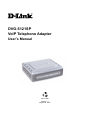
DVG-5121SP
VoIP Telephone Adapter
User’s Manual
Version 1.1
August 28, 2007
DVG-5121SP User’s Manual
1. Introduction
1-1. Product Overview..…..................................................................................................5
1-2. Product Features……………………………..……………….……………………………6
1-3. Hardware Description……………………………………………………………………...8
2. Before You Begin
2-1. Package Contents ...................................................................................................10
2-2. System Requirements …….………….………………………………………………….10
3. Installation and Applications
3-1. VoIP Telephone Adapter Assigned with a Public IP Address…………………………11
3-2. VoIP Telephone Adapter in a NAT Network………………………………………….....12
3-3. Telephone Interface Description…………………………………………..…………….13
3-4. Accessing the Web-based Configuration Utility…………………………………..……14
4. Basic Network Settings
4-1. WAN
4-1-1. Static IP…………………………………………………………………………….…….15
4-1-2. DHCP…………………………………………………………………………….………17
4-1-3. PPPoE………………………………………………………………………..………… 19
4-1-4. PPTP…...…….…………………………………...……………………………….…….21
4-1-5. L2TP……….…………………………………………………………………………….23
4-1-6. BigPond………….……………………………..………………………………………..25
4-2. LAN
LAN Setting…………………………………………………………………………….……….27
4-3. DHCP Server
4-3-1. DHCP Server Setting………..…………………………………………………………28
4-3-2. DHCP Static Map…………………………………………………………………….....29
5. Advanced Network Settings
5-1. NAT
5-1-1. NAT Setting………………………………………………………………………..……30
5-1-2. Virtual Server Setting……….………………………………………………………….32
5-1-3. Application Setting……………………………………………………………………..34
5-1-4. UPnP Setting…………………………………………………………………………...36
2
D-Link Corporation
DVG-5121SP User’s Manual
5-2. Route
Static Route………………………………………………………………………………….….37
5-3. Security
5-3-1. MAC filter………………………………………………………………………………..38
5-3-2. IP Filter…………………………………………………………………………………..39
5-3-3. URL Filter………………………………………………………………………………..40
5-3-4. Domain Filter……………………………………………………………………………41
5-3-5. Firewall…………………………………………………………………………………..42
5-3-6. Rule Summary……….………………………………………………………………….43
6. SIP Setting
6-1. Basic Setting………………………………………………………………………………44
6-2. Account Setting………………………………………………………….........................46
6-3. NAT Traversal……………………………………………………………………………..47
7. VOIP Setting
7-1. Voice Setting………………………………………………………………………………48
7-2. Call Service………………………………………………………………………………..50
7-3. Phone Setting……………………………………………………………………………..52
7-4. E.164 Setting……………………………………………………………………………...54
7-5. FAX Setting………………………………………………………………………………..55
7-6. General Dialing Setting…………………………………………………….....................56
7-7. QoS/TOS Setting……………………………………………………………………….…62
7-8. Phone Book………………………………………………………………………………..65
7-9. Call Screen……………………………………………………...…………………………66
8. Tools
8-1. Admin………………………………………………………………………………………67
8-2. Page Configure…………..………………………………………………………….…….68
8-3. Day/Time………………………………………………………………………………..….69
8-4. DDNS………………………………………………………………………………………71
8-5. System……………………………………………………………………………………..72
8-6. Firmware…………………………………………………………………………………...73
8-7. Device Setting……………………………………………………………………………..74
8-8. TR-069 Setting……………………..……………………………………………………..75
3
D-Link Corporation
DVG-5121SP User’s Manual
9. Status
9-1. Device Information………………………………………………………………………..76
9-2. Log………………………………………………………………………………………….77
9-3. IP Tables Log…………………………..………………………………………………….78
9-4. Line Status…………………………………………………………………………………79
9-5. CDR………………………………………………………………………………………...80
10. Telnet
Run Telnet……………………………………………………………………………………….81
4
D-Link Corporation
DVG-5121SP User’s Manual
1. Introduction
1-1. Product Overview
D-Link®, an industry leader in networking, introduces the DVG-5121SP VoIP Telephone Adapter
for the home environment. The DVG-5121SP VoIP Telephone Adapter converts any existing analog
telephone (corded or cordless) into an IP phone. Also, by plugging in a FAX machine, the
DVG-5121SP will enable users to send and receive faxes the same way as a traditional analog
telephone line.
The DVG-5121SP carries both voice and facsimile over the IP network. It supports the SIP
industry standard call control protocol and is compatible with free registration services or VoIP
service providers’ systems. It also supports the most popular audio CODECs to ensure
compatibility and voice quality.
The DVG-5121SP provides two FXS ports to connect to two analog telephone sets, one PSTN
lifeline port to connect to the phone line, and two Fast Ethernet (10/100) ports to connect to the
VoIP Telephone Adapter to the LAN and WAN.
VoIP service providers can configure service settings such as a server address, CODEC and
STUN settings via TFTP directly to the DVG-5121SP.
For security, all of the configuration settings are encrypted. Only VoIP service providers/resellers
with the authenticated password and user name can access them.
The DVG-5121SP features both VAD (Voice Activity Detection) and CNG (Comfort Noise
Generator) to reduce the bandwidth consumption and to sustain voice quality.
The DVG-5121SP has a built-in QoS setting to provide voice priority in IP networks and prevent
dropped calls.
5
D-Link Corporation
DVG-5121SP User’s Manual
1-2. Product Features
WAN:
One RJ-45 10/100Mbps auto-MDI/MDIX Ethernet port
WAN types: Static IP, PPPoE, DHCP, PPTP, BigPond, L2TP
VPN Pass Through
QoS: IP Precedence, DiffServ
NAT Traversal: Outbound Proxy, STUN, UPnP
SIP and RTP Priority Queuing
RTP Packet Summary: sent, received, loss packet count
NTP: Time Server, Time Zone support
DDNS: DynDns.org, EasyDNS.com, No-IP.com, dlinkddns.com
MAC Address Clone
LAN:
One RJ-45 10/100Mbps auto-MDI/MDIX Ethernet port
Router or Bridge mode
NAT / PAT
Virtual Server, DMZ
DHCP Server
Firewall: MAC Filter, IP Filter, Port Filter
VoIP:
Two FXS RJ-11 ports
One FXO RJ-11 PSTN Life Line port
Management:
LEDs: Power, Provision, WAN, LAN, Phone1, Phone2
Web-based configuration utility, TELNET
Password controlled administration
Remote firmware upgrade via TFTP or FTP
Built-in PING tool
Reset button to restore default settings
6
D-Link Corporation
DVG-5121SP User’s Manual
Voice
Pond Key
SIPv2 compliance
SIP Methods: ACK, BYE, CANCEL, INFO, INVITE, NOTIFY, OPTIONS,
PING, PRACK, REFER, REGISTER, SUBSCRIBE, UPDATE
SIP Extension: Session Timer, Proxy-Require,
P-Asserted, MWI
Voice Compression: G.711 a/u-law, G.726, G.729A/B, G.723.1
CNG and VAD
Silence suppression and detection
168 Echo Cancellation
Adaptive jitter buffer
Programmable gain control
In-band DTMF
Out-of-band DTMF relay: RFC2833
DTMF
Termination Impedance: 600/900 and complex Impedance
Failover SIP Proxy server registrations
Failsafe Mechanism (FXS relay to PSTN):
Network failure
Service unavailable
Power loss
T.30 FAX pass through, T.38 real time FAX relay
Caller ID: DTMF, FSK-Bellcore
Call Hunting support
Phone book
E.164 numbering
Hot line
Call features:
Call Hold, Call Waiting, Call Pickup
Call Forward - Unconditional, Busy, No Answer
Call Transfer - Unattended, Attended
Speed Dialing, Repeat Dialing, Three Way Calling (Media Server required)
Digit Maps
7
D-Link Corporation
DVG-5121SP User’s Manual
1-3. Diagnostic LEDs and External Interfaces
Front Panel
Power LED
Provision LED
When this LED is on, the DVG-5121SP is powered on.
The Provision LED flashes during access to the TR-069 provision ACS and turns off after
provision process finished.
When a connection is established, this LED lights up. The LED will blink to indicate
LAN LED
activity. If the LED does not light up when a cable is connected, verify the cable
connections and make sure the connected devices are powered on.
When a connection is established, this LED lights up. The LED will blink to indicate
WAN LED
network traffic is passing through the WAN port. If the LED does not light up when a cable
is connected, verify the cable connections and make sure the connected devices are
powered on.
Phone 1 LED
Phone 2 LED
8
These LEDs display the VoIP status and hook activity on the phone ports that are used to
connect to the analog telephones. If a phone connected to a phone port is off hook or in
use, this LED will light up. When a phone is ringing, the LED will blink.
D-Link Corporation
DVG-5121SP User’s Manual
Rear Panel
Side Panel
RJ11 PSTN
Life Line
Phone Port
This port connects to the wall phone line using an
RJ-11 phone cable.
Phone Ports
Each of these ports connects to an analog phone
x2
using an RJ-11 phone cable.
Use a paper clip or the tip of a pen to hold this
Reset Button
button down for 10 seconds to reset the unit to its
factory default settings. (power must be on)
Power Socket
This socket connects to the external power
adapter.
This port connects to your broadband modem or
WAN Port
router through an Ethernet cable.
This port connects to an Ethernet enabled
LAN Port
computer or IP sharing device using an Ethernet
cable.
WARNING: To avoid any possible damage to your DVG-5121SP device, do not connect the Phone 2
port to a wall phone line. If this is done, your DVG-5121SP may be damaged.
9
D-Link Corporation
DVG-5121SP User’s Manual
2. Before You Begin
2-1. Package Contents
DVG-5121SP VoIP Telephone Adapter
One CAT5 Ethernet Cable
CD-ROM
One Standard RJ-11 Phone Cable
Quick Installation Guide
12VDC 1.25A Power Adapter
If any of the above items are missing, please contact your reseller.
2-2. System Requirements for Configuration:
Make sure you have all of the following before you begin to set up the DVG-5121SP
A subscription with an Internet Service Provider (ISP)
A Computer running Windows, with a CD-ROM drive and an Ethernet port
An Ethernet-based broadband modem
A standard analog telephone
10
D-Link Corporation
DVG-5121SP User’s Manual
3. Installation and Applications
3-1. VoIP Telephone Adapter Assigned with a Public IP Address
The VoIP Telephone Adapter will have a public IP address for Internet connection regardless of whether it is a
static IP address, DHCP (using a Cable Modem), or PPPoE (Dialup / DSL).
Setting
Action
Telephone Adapter IP Settings Need to set up as static IP,
DHCP, or PPPoE
11
NAT/STUN Settings
Optional
DDNS Settings
Optional
D-Link Corporation
DVG-5121SP User’s Manual
3-2. VoIP Telephone Adapter in a NAT network
The VoIP telephone adapter uses a virtual IP address and the IP sharing function of other systems to connect
to the Internet.
Setting
LAN IP address of IP sharing
Action
Please avoid using the IP addresses 192.168.1.1-192.168.1.254 (You may
need to change the settings for IP sharing or change the LAN Port IP
address.)
VoIP Telephone Adapter IP Settings
Set as static IP address, and assign the LAN IP address for IP sharing to the
default VoIP Telephone Adapter.
NAT /STUN Settings
Enable
If the WAN setting uses a static IP address, then the NAT IP
address is set as the public IP address for IP sharing.
If the WAN setting uses a dynamic IP address, then it has to
comply with the DDNS settings. When using NAT, you must
enter the URL (Uniform Resource Locator) that is registered to
the DDNS server.
DDNS Settings
The WAN setting uses a
Disable the DDNS settings
static IP address.
The WAN setting uses a
Enable the DDNS settings: enter the registered
dynamic IP address.
URL (Uniform Resource Locator) into the
network settings -> under NAT
12
D-Link Corporation
DVG-5121SP User’s Manual
3-3. Telephone Interface Description
Connecting the DVG-5121SP to the phone sets
After connecting telephone sets to the Phone 1 and Phone 2 FXS ports, each set acts as an independent IP line
that is provided by the applied SIP server.
Connecting the DVG-5121SP to the PSTN/PBX
The Life Line port is a PSTN/ PBX <FXO> interface that connects to your telephone line for normal PSTN calls.
The Life Line port is only a back up solution enabled automatically when the network or SIP phone fails.
13
D-Link Corporation
DVG-5121SP User’s Manual
3-4. Accessing the Web-based Configuration Utility
Instructions
Step 1: Open an Internet browser.
Step 2: Enter VoIP telephone adapter’s WAN Port IP address in the website address field. If the PC is
connected to the LAN Port, enter the LAN Port IP address. The default IP address is 192.168.1.1
Step 3: Enter “admin” for the User Name and the Password is left blank. (factory default settings)
You can save the current settings on the Telephone Adapter at any time by going to the Tools > System menu
in the web-based configuration utility and clicking the Save button.
Note:
The DVG-5121SP VoIP telephone adapter doesn’t allow multiple people to configure the VoIP telephone
adapter at the same time. If a user is already logged into the system, other users from different IP
addresses cannot login at the same time. Please remember to logout or restart the system if not using
the web-based configuration utility, otherwise some of the network management features, like Telnet
will not available.
14
D-Link Corporation
DVG-5121SP User’s Manual
4. Basic Network Settings
4-1. WAN
The basic network settings are used to configure the VoIP telephone adapter’s communication ports, IP
configurations, ADSL service setting, IP tunneling, etc. Refer to the following pages for an explanation of the
different WAN settings.
4-1-1. Static IP
Every computer on the Internet has an address, similar to the way every building on a street has an address.
This allows you to distinguish between every computer on the Internet. You may have come across a number
such as "198.69.121.3" or something similar. This is an Internet Protocol (IP) address.
WAN Port IP Assignment: Select Static IP if your ISP (Internet Service Provider) assigned you a fixed IP address,
subnet mask, and DNS server addresses. Please contact your local ISP if you have
any questions about these settings.
Basic Network Setting > WAN > Static IP
15
D-Link Corporation
DVG-5121SP User’s Manual
Host Name: The Host Name is optional but may be required by some ISPs. The default host name is the
device name of the VoIP Telephone Adapter and may be changed.
WAN Port MAC: The default MAC Address is set to the WAN’s physical interface MAC address on the VoIP
telephone adapter. It is not recommended that you change the default MAC address unless
required by your ISP. You can use the Clone MAC Address button to replace the WAN port
MAC address with the MAC address of the Ethernet card on your computer. Select Manual
Setting to manually change the WAN Port MAC address.
Ping from WAN: While enabled, this allows pings from the WAN through the Internet to check if the device is
working or not.
MTU: You may need to change the MTU (Maximum Transmission Unit) for optimal performance with your
specific ISP. 1500 bytes is the default MTU.
IP Address: Enter the IP address assigned by your ISP.
Subnet Mask: Enter the subnet mask assigned by your ISP.
Default Gateway: Enter the default gateway assigned by your ISP.
Set DNS server: Enter the Primary and Secondary DNS server IP addresses assigned by your ISP.
16
D-Link Corporation
DVG-5121SP User’s Manual
4-1-2. DHCP
DHCP (Dynamic Host Configuration Protocol) enables individual computers on an IP network to extract their
configurations from a server (the DHCP server) or servers, in particular, servers that have no exact information
about the individual computers until they request the information. The overall purpose of this is to reduce the
work necessary to administer a large IP network. The most significant piece of information distributed in this
manner is the IP address.
WAN Port IP Assignment: Select DHCP (the most common setting) to configure the WAN port MAC, WAN port
ping, and DNS server settings.
Basic Network Setting > WAN > DHCP
Host Name: The Host Name is optional but may be required by some ISPs. The default host name is the
device name of the telephone adapter and may be changed.
17
D-Link Corporation
DVG-5121SP User’s Manual
WAN Port MAC: The default MAC Address is set to the WAN’s physical interface MAC address on the VoIP
telephone adapter. It is not recommended that you change the default MAC address unless
required by your ISP. You can use the Clone MAC Address button to replace the WAN port
MAC address with the MAC address of the Ethernet card on your computer. Select Manual
Setting to manually change the WAN Port MAC address.
Ping from WAN: While enabled, this allows pings from the WAN through the Internet to check if the device is
working or not.
MTU: You may need to change the MTU (Maximum Transmission Unit) for optimal performance with your
specific ISP. 1500 bytes is the default MTU.
Set DNS server: The default setting is “Automatically.” If you choose “Manually”, you must enter the Primary
and Secondary DNS server IP addresses assigned by your ISP.
18
D-Link Corporation
DVG-5121SP User’s Manual
4-1-3. PPPoE (DSL)
PPPoE (Point-to-Point Protocol over Ethernet) is a proposal specifying how a host personal computer (PC)
interacts with a broadband modem to achieve access to the growing number of high-speed data networks.
Relying on two widely accepted standards, Ethernet and the point-to-point protocol (PPP), the PPPoE
implementation requires virtually no more knowledge on the part of the end user other than that required for
standard dial-up Internet access. In addition, PPPoE requires no major changes in the operational model for
Internet Service Providers (ISPs) and carriers. The significance of PPPoE has to do with its far greater ease of
use versus competing approaches.
WAN Port IP Assignment: Select PPPoE.
Basic Network Setting > WAN > PPPoE
Host Name: The Host Name is optional but may be required by some ISPs. The default host name is the device
name of the telephone adapter and may be changed.
19
D-Link Corporation
DVG-5121SP User’s Manual
WAN Port MAC: The default MAC Address is set to the WAN’s physical interface MAC address on the VoIP
telephone adapter. It is not recommended that you change the default MAC address unless
required by your ISP. You can use the Clone MAC Address button to replace the WAN port
MAC address with the MAC address of the Ethernet card on your computer. Select Manual
Setting to manually change the WAN Port MAC address.
Ping from WAN: While enabled, this allows pings from the WAN through the Internet to check if the device is
working or not.
MTU: You may need to change the MTU (Maximum Transmission Unit) for optimal performance with your
specific ISP. 1500 bytes is the default MTU.
PPPoE Username: Enter your PPPoE user name.
PPPoE Password: Enter your PPPoE password and then retype the password in the next box.
Service Name: Enter the ISP Service Name (optional).
IP Address: Enter the IP address (Static PPPoE only).
Connect Type: Select either Keep Alive or Manual on.
Max Idle Time: Enter a maximum idle time during which the Internet connection is maintained during inactivity.
To disable this feature, select Keep Alive as the connect type.
Set DNS server: The default setting is “Automatically.” If you choose “Manually”, you must enter the Primary
and Secondary DNS server IP addresses assigned by your ISP.
20
D-Link Corporation
DVG-5121SP User’s Manual
4-1-4. PPTP
PPTP (Point-to-Point Tunneling Protocol) was developed by a consortium including Microsoft and is used for
establishing VPN (Virtual Private Network) tunnels across the Internet. This allows remote users to securely and
inexpensively access their corporate network from anywhere on the Internet.
PPTP uses a client-server model for establishing VPN connections. Most Microsoft operating systems ship with
a PPTP client, so there is no need to purchase third-party client software. PPTP has the additional advantage
over other VPN technologies of being easy to setup.
WAN Port IP Assignment: Select PPTP.
Basic Networking Setting > WAN > PPTP
Host Name: The Host Name is optional but may be required by some ISPs. The default host name is the device
name of the telephone adapter and may be changed.
21
D-Link Corporation
DVG-5121SP User’s Manual
WAN Port MAC: The default MAC Address is set to the WAN’s physical interface MAC address on the VoIP
telephone adapter. It is not recommended that you change the default MAC address unless
required by your ISP. Select Manual Setting to manually change the WAN Port MAC address.
Ping from WAN: While enabled, this allows pings from the WAN through the Internet to check if the device is
working or not.
MTU: You may need to change the MTU (Maximum Transmission Unit) for optimal performance with your specific
ISP. 1500 bytes is the default MTU.
IP Address: Enter the IP address provided by your ISP. (Static PPTP only)
Subnet Mask: Enter the subnet mask provided by your ISP. (Static PPTP only)
Gateway: Enter the gateway provided by your ISP. (Static PPTP only)
Server IP/Name: Enter the Server IP provided by your ISP (optional).
PPTP Account: Enter your PPTP account name.
PPTP Password: Enter your PPTP password and then retype the password in the next box.
Connect Type: Select either Keep Alive or Manual on.
Max Idle Time: Enter a maximum idle time during which the Internet connection is maintained during inactivity. To
disable this feature, select Keep Alive as the connect type.
Set DNS server: The default setting is “Automatically.” If you choose “Manually”, you must enter the Primary and
Secondary DNS server IP addresses assigned by your ISP.
22
D-Link Corporation
DVG-5121SP User’s Manual
4-1-5. L2TP
L2TP (Layer Two Tunneling Protocol) is an extension of the Point-to-Point Tunneling Protocol (PPTP) used by
an Internet service provider (ISP) to enable the operation of a virtual private network (VPN) over the Internet.
WAN Port IP Assignment: Select L2TP.
Basic Network Setting > WAN > L2TP
Host Name: The Host Name is optional but may be required by some ISPs. The default host name is the device
name of the telephone adapter and may be changed.
WAN Port MAC: The default MAC Address is set to the WAN’s physical interface MAC address on the VoIP
telephone adapter. It is not recommended that you change the default MAC address unless
required by your ISP. Select Manual Setting to manually change the WAN Port MAC address.
23
D-Link Corporation
DVG-5121SP User’s Manual
Ping from WAN: While enabled, this allows pings from the WAN through the Internet to check if the device is
working or not.
MTU: You may need to change the MTU (Maximum Transmission Unit) for optimal performance with your specific
ISP. 1400 bytes is the default MTU.
IP Address: Enter the IP address provided by your ISP. (Static L2TP only)
Subnet Mask: Enter the subnet mask provided by your ISP. (Static L2TP only)
Gateway: Enter the gateway provided by your ISP. (Static L2TP only)
Server IP/Name: Enter the Server IP provided by your ISP (optional).
L2TP Account: Enter your L2TP account name.
L2TP Password: Enter your L2TP password and then retype the password in the next box.
Connect Type: Select either Keep Alive or Manual on.
Max Idle Time: Enter a maximum idle time during which the Internet connection is maintained during inactivity. To
disable this feature, select Keep Alive as the connect type.
Set DNS server: The default setting is “Automatically.” If you choose “Manually”, you must enter the Primary and
Secondary DNS server IP addresses assigned by your ISP.
24
D-Link Corporation
DVG-5121SP User’s Manual
4-1-6. BigPond
This service is supported in Australia only.
WAN Port IP Assignment: Select BigPond.
Basic Network Setting > WAN > BigPond
Host Name: The Host Name is optional but may be required by some ISPs. The default host name is the device
name of the Router and may be changed.
WAN Port MAC: The default MAC Address is set to the WAN’s physical interface MAC address on the VoIP
telephone adapter. It is not recommended that you change the default MAC address unless
required by your ISP. You can use the Clone MAC Address button to replace the WAN port MAC
address with the MAC address of the Ethernet card on your computer. Select Manual Setting to
manually change the WAN Port MAC address.
25
D-Link Corporation
DVG-5121SP User’s Manual
Ping from WAN: While enabled, this allows pings from the WAN through the Internet to check if the device is
working or not.
BigPond Account: Enter your BigPond user name.
BigPond Password: Enter your BigPond password and then retype the password in the next box.
Auth Server: Select sm_server or dce_server from the drop-down menu.
Server IP/Name: Enter the IP address of the login server.
26
D-Link Corporation
DVG-5121SP User’s Manual
4-2. LAN
LAN setting
This section will allow you to change the local network settings of the telephone adapter and configure the DHCP
settings.
Basic Network Setting > LAN
LAN IP Address: Enter the LAN IP address of the telephone adapter. The default IP address is 192.168.1.1.If you
change the IP address, after you click the Submit button, you will need to enter the new IP
address in your browser to get back into the configuration.
Subnet Mask: Enter the Subnet Mask. The default subnet mask is 255.255.255.0.
DNS Proxy: Enable the DNS Proxy to transfer the DNS server information from your ISP to your computers. If
disabled, your computers will use the telephone adapter for a DNS server.
27
D-Link Corporation
DVG-5121SP User’s Manual
4-3. DHCP Server
Basic Network Setting > DHCP Server
4-3-1. DHCP Server Setting
The DVG-5121SP has a built-in DHCP (Dynamic Host Control Protocol) server.
The DHCP Server will automatically assign an IP address to the computers on the LAN/
private network. Be sure to set your computers to be DHCP clients by setting their TCP/
IP settings to “Obtain an IP Address Automatically.” When you turn on your computers,
they will automatically load the proper TCP/IP settings provided by the DVG-5121SP. The
DHCP Server will automatically allocate an unused IP address from the IP address pool
to the requesting computer. You must specify the starting and ending address of the IP
address pool.
28
D-Link Corporation
DVG-5121SP User’s Manual
DHCP Server: Select Enable or Disable. The default setting is Enable.
Assigned DHCP IP Address: Set the starting IP address and the ending IP address for the DHCP server’s IP
assignment.
DHCP IP Lease Time: The length of time for the IP lease. Select the Lease time from the drop-down menu. The
default setting is one hour.
4-3-2. DHCP Static Map
DHCP Static Map: Select Enable or Disable. The default setting is Disable.
IP: Enter the IP address of the client.
MAC: Enter the MAC address of the client.
Description: Enter any in order to distinguish from other clients.
29
D-Link Corporation
DVG-5121SP User’s Manual
5. Advanced Network Settings
U
5-1. NAT
5-1-1. NAT Setting
Advanced Network Setting > NAT > NAT Setting
NAT Settings: You can choose what kinds of NAT need to be supported in this page.
MASQUERADE: IP masquerading allows one or more workstations on a LAN to be concealed behind a single Linux
machine connected to the Internet. The workstations on the LAN can access the Internet almost
transparently even without valid IP addresses. The Linux box rewrites outgoing packets from the
LAN to the Internet in such a way that they appear to originate from the Linux machine. Response
packets coming back in are re-written and routed back to the correct workstations on the LAN.
This arrangement allows many Internet applications to run transparently from the LAN
workstations.
30
D-Link Corporation
DVG-5121SP User’s Manual
IPSec Pass Through: IPsec is a framework for a set of protocols for security at the network or packet processing
layer of network communication. Enable or Disable this framework verification.
PPTP Pass Through: PPTP is a protocol that allows corporations to extend their own corporate network through
private tunnels over the public Internet. Enable or Disable this protocol verification.
L2TP Pass Through: L2TP is an extension to PPP, which is an important component for VPNs. VPNs allow users
and telecommuters to connect to their corporate intranets or extranets. Enable or Disable this
function.
SIP ALG: SIP ALG (Application Layer Gateway) is a signaling protocol for Internet conferencing, telephony,
presence, events notification and instant messaging. Enable or Disable this protocol verification.
NetMeeting ALG: NetMeeting ALG (Application Layer Gateway) is used to configure the different accessibility
options of your system. It enables an authorized user to access this computer remotely by using
NetMeeting over a corporate intranet. Enable or Disable this protocol verification.
DMZ: If you have multiple PCs, you can choose one of the computers to be between the Internet connection and the
firewall. This exposes that computer to the Internet without security and should only be enabled if absolutely
necessary. Enable or Disable this function.
31
D-Link Corporation
DVG-5121SP User’s Manual
5-1-2. Virtual Server Setting
Advanced Network Setting > NAT > Virtual Server Setting
Virtual Server: Select Enable or Disable.
Private IP: Enter the IP address of the server computer in the LAN (Local Area Network) that will be providing the
virtual services.
Protocol Type: Select the protocol used for the virtual server.
Private Port: Enter the port number of the service used by the Private IP computer.
Public Port: Enter the port number on the WAN (Wide Area Network) side will be used to access the virtual server.
32
D-Link Corporation
DVG-5121SP User’s Manual
Schedule: The schedule of time when the virtual server will be enabled. The schedule may be set to Always,
which allows the particular server to always be enabled. If it is set to By Schedule, select the time frame
for the server to be enabled.
Example: You have a Web server that you want Internet users to be able to access at all times. The Web
(HTTP) server is on the LAN (Local Area Network) computer 192.168.0.25. HTTP uses port 80, TCP.
Use the following settings:
Name: Web Server
Private IP: 192.168.0.25
Protocol Type: TCP
Private Port: 80
Public Port: 80
Schedule: Always
33
D-Link Corporation
DVG-5121SP User’s Manual
5-1-3. Application Setting
Some applications require multiple connections, such as Internet gaming, video conferencing, Internet telephony
and others. These applications have difficulties working through NAT (Network Address Translation). Special
Applications makes some of these applications work with the DVG-5121SP. If you need to run applications that
require multiple connections, specify the port normally associated with an application in the Trigger Port field, select
the protocol type as TCP or UDP, then enter the public ports associated with the trigger port to open them for
inbound traffic.
Advanced Network Setting > NAT > Application Setting
Special Application: Select Enable or Disable.
Trigger Port: This is the port used to trigger the application. It can be either a single port or a range of ports.
Trigger Type: This is the protocol used to trigger the special application.
34
D-Link Corporation
DVG-5121SP User’s Manual
Public Port: This is the port number on the WAN side that will be used to access the application. You may define a
single port or a range of ports. You can use a comma to add multiple ports or port ranges.
Public Type: This is the protocol used for the special application.
Schedule: The schedule of time when the special application will be enabled. The schedule may be set to Always,
which allows the particular application to always be enabled. If it is set to By Schedule, select the time
frame for the application to be enabled.
Note! These settings are for advanced users only. Incorrect settings will cause the phone to work improperly.
Contact your ITSP for more information or assistance. The DVG-5121SP does not support the feature
for making a call without registering to a Proxy.
35
D-Link Corporation
DVG-5121SP User’s Manual
5-1-4. UPnP Setting
Advanced Network Setting > NAT > UPnP
UPNP Internet Gateway Device: Select Enable or Disable. UPnP provides compatibility with networking equipment,
software and peripherals of the over 400 vendors that cooperate in the Plug and
Play forum.
36
D-Link Corporation
DVG-5121SP User’s Manual
5-2. Route
Static Route
Advanced Network Setting > Route > Static Route
If the WAN setting uses a static IP address, then the NAT IP address is set as the Public IP address for IP sharing.
Static Route: Select Enable or Disable.
Type: Select net or host from the drop-down menu.
Target: Input the public IP Address provided by your ISP or the server.
Netmask: Enter the subnet mask. (All devices in the network must have the same subnet mask.)
Gateway: Enter the gateway provided by your ISP.
37
D-Link Corporation
DVG-5121SP User’s Manual
5-3. Security
5-3-1. MAC Filter
Advanced Network Setting > Security > MAC Filter
Use MAC (Media Access Control) Filters to allow or deny LAN (Local Area Network) computers by their MAC
addresses from accessing the network.
MAC Filter: Select Enable or Disable.
Active: Select Yes or No.
MAC Address: Enter the MAC Address.
Schedule: The schedule of time when the MAC filter will be enabled. The schedule may be set to Always,
which allows the particular filter to always be enabled. If it is set to By Schedule, select the time frame
for the filter to be enabled.
Log: Select Enable or Disable.
38
D-Link Corporation
DVG-5121SP User’s Manual
5-3-2. IP Filter
Advanced Network Setting > Security > IP Filter
IP Filter: Use IP Filters to deny LAN IP addresses from accessing the Internet. You can deny specific port numbers
or all ports for the specific IP address. Select Enable or Disable.
Active: Select Yes or No.
IP: Enter the IP address or a range of IP addresses of the LAN computer(s) that will be denied Internet access.
Port: The single port or port range that will be denied access to the Internet.
Protocol Type: Select the protocol type from the drop-down menu.
Schedule: The schedule of time when the IP filter will be enabled. The schedule may be set to Always,
which allows the particular filter to always be enabled. If it is set to By Schedule, select the time frame
for the filter to be enabled.
Log: Select Enable or Disable.
39
D-Link Corporation
DVG-5121SP User’s Manual
5-3-3. URL Filter
Advanced Network Setting > Security > URL Filter
URL Filter: Select Enable or Disable.
Active: Select Yes or No.
Client IP: Enter the IP address or a range of IP addresses.
URL Filter String: Enter the URL filter string.
Log: Select Enable or Disable.
40
D-Link Corporation
DVG-5121SP User’s Manual
5-3-4. Domain Filter
Advanced Network Security > Security > Domain Filter
Domain Filter: Select Enable or Disable.
Active: Select Yes or No.
Client IP: Enter the IP address or a range of IP addresses.
Domain Filter String: Enter the URL filter string.
Log: Select Enable or Disable.
41
D-Link Corporation
DVG-5121SP User’s Manual
5-3-5. Firewall
Advanced Network Setting > Security > Firewall
Firewall: Select Enable or Disable.
Active: Select Yes or No.
Action: Select Allow or Deny.
Source: Choose WAN or LAN as the Source and enter a range of IP Addresses on the Internet that you would like
this rule applied to. Enter the IP Address of the computer on your local network that you want to allow the
incoming service to. This will not work with a range of IP Addresses.
Destination: Select LAN or WAN as the Destination and enter the IP Address of the computer on your local network
that you want to allow the incoming service to. This will not work with a range of IP Addresses. Enter
the port or range of ports that are required to be open for the incoming service.
Schedule: The schedule of time when the firewall will be enabled. The schedule may be set to Always,
which allows the particular firewall to always be enabled. If it is set to By Schedule, select the time frame
for the firewall to be enabled.
Log: Select Enable or Disable.
42
D-Link Corporation
DVG-5121SP User’s Manual
5-3-6. Rule Summary
This page contains a list of all the security settings rules.
43
D-Link Corporation
DVG-5121SP User’s Manual
6. SIP Setting
6-1. Basic Setting
SIP Setting > Basic Setting
SIP Port Number: This is also called an outbound proxy. The SIP (Session Initiation Protocol) Port Number handles
SIP call signaling as a standard SIP proxy server. It receives and transmits phone conversation
traffic (media) between two VoIP telephone adapters. This option tells the VoIP telephone
adapter to send and receive all SIP packets to the destined outbound proxy server rather than
the remote VoIP telephone adapter. This helps VoIP calls to pass through any NAT protected
network without additional settings or techniques. Please make sure your VoIP service provider
supports outbound proxy services before you enable it.
44
D-Link Corporation
DVG-5121SP User’s Manual
Session Timer: This setting can help to avoid excessive billing due to a dropped call.
Media Port Start: Enter the beginning of the listening port range.
Media Port End: Enter the end of the listening port range.
Transport: Select UDP or TCP from the drop-down menu.
SIP Time Interval: Enter the desired time interval which the VoIP telephone adapter will report to Proxy Server.
Timeout for Invite: The time for the server to invite the clients to connect.
Timeout for Ring Back: The time for ring back control while making a call.
Timeout for Release: The time for the VoIP telephone adapter to release from the server.
Registration Retry Count: Retry Count timing.
Registration Retry Interval: The time between each retry connection.
PING Interval: The time between ping packets.
SIP User Agent Name: The default setting is VOIP_Agent_001.
PRACK: The default setting for PRACK (Provisional Response Acknowledgement) is Disable.
45
D-Link Corporation
DVG-5121SP User’s Manual
6-2. Account Setting
SIP Setting > Account Setting
Authentication Expired Time: The time for authentication expiration.
Note! These settings are for advanced users only. Incorrect settings will cause the phone to work improperly.
Contact your ITSP for more information or assistance. The DVG-5121SP does not support the feature for making a
call without registering to a Proxy.
46
D-Link Corporation
DVG-5121SP User’s Manual
6-3. NAT Traversal
SIP Setting > NAT Traversal
NAT Traversal: Select Enable or Disable.
Traversal By: Select STUN or UPNP. Use STUN to prevent problems with setting the IP sharing function, but some
NAT do not support this protocol. Use UPnP to enable the VoIP telephone adapter’s IP traffic to pass
through a NAT server. This function only works when the NAT server supports UPnP and has it
enabled.
SIP NAT Keep Alive: Select Enable or Disable. Enter the time value for keep alive.
47
D-Link Corporation
DVG-5121SP User’s Manual
7. VOIP Setting
7-1. Voice Setting
VoIP Setting > Voice Setting
Packet Length: Select a packet length from the drop-down menu.
G.726 32K Payload Type Value: Select the payload type value from the drop-down menu.
Outband 2833 Payload Type Value: Select the payload type value from the drop-down menu.
RTP Timeout: Enter a value for the RTP timeout.
RTP Packet Lost Percentage: Enter the percentage for RTP packet lost.
Maximum ICMP Unreachable: Enter a value for the maximum ICMP unreachable.
48
D-Link Corporation
DVG-5121SP User’s Manual
PSTN Switch Mode: Select Auto Mode or Always PSTN from the drop-down menu.
Codec Priorities: Use this field to select the type of voice coder/decoder (codec) priority you want to use.
G.711/ Ulaw: Operates at 64 Kbps (standard), 56 Kbps, and 48 Kbps (non-standard).
Compresses frames of 14-bit linear PCM samples into frames of 8-bit logarithmic PCM code
words.
G.711/ Alaw: Operates at 64 Kbps (standard), 56 Kbps, and 48 Kbps (non-standard).
Compresses 13-bit linear PCM samples into 8-bit logarithmic PCM code words.
G723.1: Operates at 6.3 Kbps and 5.3 Kbps. compression and decompression of 8 kHz speech signals.
G726: Operates at 40, 32, 24, and 16 Kbps.
G.729a/b: Operates on 10ms frames with short algorithm delays.
Compresses 8 kHz CODEC or linear audio data to 8 kbps.
iLBC: Internet Low Bit Rate Codec (iLBC) is a royalty free narrowband speech codec. Operates at 15 to 20
Kbps.
G.723 Rate: Select the G.723 rate from the drop-down menu.
iLBC mode: Select the iLBC mode from the drop-down menu.
DTMF Method: Choose what kind of pass through mode you want for the DTMF transmission.
Voice Active Detector: Select an option for silence suppression from the drop-down menu.
Line Echo Canceller Tail Length: G.168 is an ITU-T standard for eliminating the echo caused by the second by the
sound of your voice reverberating in the telephone receiver while calling.
Acoustic Echo Canceller Tail Length: Acoustic echo is caused by direct and indirect feedback from speaker to
microphone. You can control the specific canceller tail length based on any
required local settings.
Automatic Gain Control Tx Level: Select the gain transmission level from 0 to 30.
Automatic Gain Control Rx Level: Select the gain transmission level from 0 to 30.
49
D-Link Corporation
DVG-5121SP User’s Manual
7-2. Call service
VoIP Setting > Call Service
Call Waiting: Select Enable or Disable.
Call Waiting Timeout- The waiting timeout can be set if the call waiting function is enabled.
Call Hunting Group: Select Enabled or Disabled.
Call Repeat Timeout: Select a call repeat timeout value from the drop-down menu.
Call Transfer Option: Allow or deny the call transfer function for the specific phone port.
Call Forward Option: Allow or deny the call forward function for the specific phone port.
50
D-Link Corporation
DVG-5121SP User’s Manual
Call Forward Always URI: Enter the Forward Always Number for the automatic dialing function.
Call Forward on Busy URI: Enter the Forward on Busy Number for the automatic dialing function.
Call Forward on NoAnswer URI: Enter the Forward on No Answer Number for the automatic dialing function.
Call Forward on NoAnswer Timeout: Enter the Forward on NoAnswer Timeout value.
Do Not disturb: Select Enabled or Disabled.
Hot Line: When the phone is picked up, the VoIP telephone adapter automatically dials your assigned hotline
number. While in hotline mode, other lines cannot be used. Select Enable or Disable.
Hot Line URI: Enter the hot line number for the automatic dialing function.
Anonymous Call: This is for outgoing calls and is used to prevent a caller from reaching a number when the caller has
explicitly restricted the phone number on Caller ID.
Reject Anonymous Call Coming: Anonymous Call Rejection is for incoming calls and rejects calls from callers who have
blocked the display of their number. Only deliberate anonymous numbers are rejected..
51
D-Link Corporation
DVG-5121SP User’s Manual
7-3. Phone Setting
VoIP Setting > Phone Setting
Tone Setting: Select the tone setting for your local area.
Caller ID Type: Select FSK type. In most cases, Bellcore is preferred in North America and ETSI in Europe.
Note: If you register the VoIP telephone adapter to a Proxy, you may be unable to make a call. This is due to
the fact that the VoIP telephone adapter doesn’t send the number for authorization.
Caller ID Power Level: Enter a value for the power level.
Caller ID Display: Shows caller ID in device information. Select Before Ring or After Ring.
52
D-Link Corporation
DVG-5121SP User’s Manual
Caller ID Type 1 Alerting Signal: Select the alerting signal type for when the phone is on-hook.
DTAS: Dual Tone Alert Signal
RPAS: Ring Pulse Alert Signal
LR: Line Reversal
LR-DTAS: Line Reversal and Dual Tone Alert Singal
Caller ID Type 2 Alerting Signal: Select the alerting signal type for when the phone is off-hook.
Ring Impedance: Select the ring impedance based on your local requirements. Please contact your ITSP for more
information.
Hook Flash Detect Upper Bound: Enter a value for Hook Flash Detect upper bound.
Hook Flash Detect Lower Bound: Enter a value for Hook Flash Detect lower bound.
Voice Tx Level: Select a voice transmission level from the drop-down menu.
Voice Rx Level: Select a voice receiving level from the drop-down menu.
53
D-Link Corporation
DVG-5121SP User’s Manual
7-4. E.164 Setting
VoIP Setting > E.164 Setting
E.164 Enable: Select Enable or Disable.
Country Code: Enter the country code.
Area Code: Enter the area code.
Note: It depends on the proxy if you want to invite the proxy to follow the E.164 rule. If you fail to make a call, please
contact your ITSP.
54
D-Link Corporation
DVG-5121SP User’s Manual
7-5. FAX Setting
VoIP Setting > FAX Setting
T.38 Option: Select on of the following options from the drop-down menu:
Voice: voice data
T.38 FAX Relay: Integrated and tested with Fax data modems at rates of up to 14.4 kbps. UDP and
TCP support.
Voice and T.38 FAX Relay: both voice and T.38 Fax relay
Voice and T.38 Fax Pass Through: bridge mode
55
D-Link Corporation
DVG-5121SP User’s Manual
7-6. General Dialing Setting
VoIP Setting > General Dialing Setting > B Type
Inter-digit Timeout: If no other number is being dialed within this interval, the Telephony ATA will terminate this call.
First-digit Timeout: If the phone is picked up and no number is dialed within this period of time, the tone will change
to a busy tone
Call feature Type: Select A type (general) or B type (USA).
The call feature key control is listed on the following 2 pages for B type and A type.
56
D-Link Corporation
DVG-5121SP User’s Manual
B Type (default) Setting
Call hold: Push the phone set flash hook one time to enable this function while holding a call.
Note: The flash hook pushing time can’t be longer than 1/2 second.
Three Way Conference: Set up a call, then push the phone set flash hook once.
Note: The flash hook pushing time can’t be longer than 1/2 second.
Call Waiting Cancel Code: Default *70
Forward Always Active Code: Default *72
Forward Always Deactive Code: Default *73
Forward Busy Active Code: Default *90
Forward Busy Deactive Code: Default *91
Forward Noanswer Active Code: Default *92
Forward Noanswer Deactive Code: Default *93
Do Not Disturb Active Code: Default *78
Do Not Disturb Deactive Code: Default *79
Call Return Code: Default *69
Anonymous Call/Block Caller ID (Per Call) Code: Default *67
Call Repeat/Call Back on Busy Active Code: Default *66
Call Repeat/Call Back on Busy Deactive Code: Default *86
Screen Last Incoming Call Code: Default *60
Call Pickup Code: Default *98
Pound Key (#): Select Enable or Disable.
57
D-Link Corporation
DVG-5121SP User’s Manual
A Type Setting
VoIP Setting > General Dialing Setting > A Type
Call hold: Push the phone set flash hook one time to enable this function while holding a call.
Note: The flash hook pushing time can’t be longer than 1/2 second.
Transfer Code: Default *#
New Call Code: Default **
Three Way Conference: Default *71
Call Waiting Cancel Code: Default *70
Forward Always Active Code: Default *72
Forward Always Deactive Code: Default *73
Forward Busy Active Code: Default *90
Forward Busy Deactive Code: Default *91
58
D-Link Corporation
DVG-5121SP User’s Manual
Forward Noanswer Active Code: Default *92
Forward Noanswer Deactive Code: Default *93
Do Not Disturb Active Code: Default *78
Do Not Disturb Deactive Code: Default *79
Call Return Code: Default *69
Anonymous Call/Block Caller ID (Per Call) Code: Default *67
Call Repeat/Call Back on Busy Active Code: Default *66
Call Repeat/Call Back on Busy Deactive Code: Default *86
Screen Last Incoming Call Code: Default *60
Call Pickup Code: Default *98
Pound Key (#): Select Enable or Disable.
59
D-Link Corporation
DVG-5121SP User’s Manual
Digit Map Setting
VoIP Setting > General Dialing Setting > Digit Map Setting
The VoIP digit map allows VoIP calls with leading digits and length matching the rules specified to be dialed out
immediately. It is a phone dialing plan that defines specific phone dialing behavior so the phone can know when an
entered number is complete and therefore that the call should be initiated.
Digit Map Setting: Select Yes or No to enable or disable the digit map setting.
Applied Port: Select Port 1, Port 2, or ALL.
Digit Map Rule: The digit map is defined by a case insensitive string. It is a set of digits or timers, or an expression
over which the gateway will attempt to find a shortest possible match. The following constructs can
be used in each numbering scheme:
60
D-Link Corporation
DVG-5121SP User’s Manual
Individual Keys: 0, 1…. 9, *, and #
Timer: The letter “x” which matches any numeric digit (0 to 9).
Range: One or more keys enclosed between square brackets ( “[“ and “]”).
Sub-range: Two numeric digits separated by a hyphen (“-”) which matches any digit between and including
the two. The sub-range construct can only be used inside a range construct.
Repetition: A period (“.”) which matches an arbitrary number, including zero, of occurrences of the preceding
construct.
Example: Assume we have the 4 rules as follows:
(1) 0 [12]
(2) 00
(3) 1[12].1
(4) 2x.#
Given the input “0”, a match will occur immediately since position (“.”) allows for zero occurrences of the preceding
construct. The input “00” can thus never be produced in this digit map.
Give the input “1”, only a partial match exists. The input “12” is also only a partial match; however both “11” and
“121” are a match.
Given the input “2” a partial match exists. A partial match also exists for the input “23”, “234”, “2345”, etc. A full match
does not occur here until a “#” is generated, for example “2345#”. The input “2#” would also have been a match.
Policy Type: Select a policy type from the drop-down menu.
Policy: Enter the prefix and replace for the policy.
Note: Enter a note for the specific digit map setting.
61
D-Link Corporation
DVG-5121SP User’s Manual
7-7. QoS/TOS Setting
TOS
VoIP Setting > QOS/TOS Setting > TOS
Network traffic can be classified by setting the TOS (Type of Service) values at the data source so a server can
decide the best method of delivery (least cost, fastest route, etc.).
SIP TOS: Select an option from the drop-down menu.
RTP TOS: Select an option from the drop-down menu.
62
D-Link Corporation
DVG-5121SP User’s Manual
DiffServ
VoIP Setting > QOS/TOS Setting > DiffServ
DiffServ is a class of service (COS) model that marks packets so that they receive specific per-hop treatment. In
addition, applications do not have to request a particular service or give advanced notice of whether traffic is going.
SIP DiffServ: Enter a value for SIP DiffServ. The default value is 16.
RTP DiffServ: Enter a value for RTP DiffServ. The default value is 16.
63
D-Link Corporation
DVG-5121SP User’s Manual
QoS Priority Setting
VoIP Setting > QOS/TOS Setting > QOS Priority Setting
Quality of Service (QoS) refers to a network’s ability to deliver data with minimum delay and the networking method
used to provide bandwidth for real-time multimedia applications.
Priority: Select Enable or Disable.
Voice Priority: Select a value from the drop-down menu.
Voice VLAN ID: Enter a value for the voice VLAN ID.
Data Priority: Select a value from the drop-down menu.
DATA VLAN ID: Enter a value for the data VLAN ID.
64
D-Link Corporation
DVG-5121SP User’s Manual
7-8. Phone Book
VoIP Setting > Phone Book
Up to 50 phone numbers can be stored in the phone book. SpeedDial Digit provides shortcuts (#0 to #9) for dialing
frequently used VoIP phones.
65
D-Link Corporation
DVG-5121SP User’s Manual
7-9. Call Screen
VoIP Setting > Call Screen
Use the Call Screen page to enter phone numbers you want to reject. Incoming calls and outgoing calls can be
rejected. Enter the phone number, click the Submit button, and the phone number that was just entered will be
displayed on the page.
66
D-Link Corporation
DVG-5121SP User’s Manual
8. Tools
8-1. Admin
Tools > Admin
Account Level: Select Admin, User, or Guest for the account level.
Account Name: Enter the account name.
Account Password: Enter the password to be used for authentication.
Confirm Password: Reenter the password to be used for authentication.
Login Timeout: Enter a value for the login timeout.
Remote administration: Select Enable or Disable.
67
D-Link Corporation
DVG-5121SP User’s Manual
8-2. Page Configure
Tools > Page Configure
WEB Page Authority Setting: Choose one of the pages from the WEB Page Authority List to change the view level
and configure level as Admin, User, Guest, or non Authority.
68
D-Link Corporation
DVG-5121SP User’s Manual
8-3. Day/Time
Tools > Day / Time > Manual Time Setting
Manual Time Setting: Select manual time setting to manually input the time by entering the values for the Year,
Month, Day, Hour, Minute, and Second. Click the Computer Clock button to copy your
computer’s time.
NTP Time Server: NTP (Network Time Protocol) synchronizes computer clock times in a network of computers.
Enter the IP address of the NTP server in the box for NTP Server Address (see the screen shot
on the following page).
Time Zone: Select the time zone.
69
D-Link Corporation
DVG-5121SP User’s Manual
Daylight Saving Settings
Tools > Day / Time > NTP Time Server
Enable Daylight Saving: Check the box to enable the Daylight saving function. Select the DST start and end time
from the drop-down menus.
Please refer to the DST setting area and duration below.
United States
Year
DST Begins at 2
a.m.
EU
DST Ends
at 2
a.m.
Summertime
Summertime
period begins at 1
period ends at 1
a.m. UT
a.m. UT
2007
March 11
November 4
March 25
October 28
2008
March 9
November 2
March 30
October 26
2009
March 8
November 1
March 29
October 25
2010
March 14
November 7
March 28
October 31
US calculator valid 1976-2099; EU 1996-2099.
70
D-Link Corporation
DVG-5121SP User’s Manual
8-4. DDNS
Tools > DDNS
DDNS (Dynamic Domain Name System) is a method of keeping a domain name linked to a changing IP Address.
This is a useful feature since many computers do not use a static IP addresses.
DDNS: Select Enable or Disable.
DDNS Server Type: Select a DDNS server type from the drop-down menu.
DDNS Username: Enter the DDNS username.
DDNS Password: Enter the DDNS password and reenter it in the next box to confirm.
Hostname to register: Enter another domain name to replace the selected DDNS server (optional).
71
D-Link Corporation
DVG-5121SP User’s Manual
8-5. System
Tools > System
PING Test: Enter the host name or an IP address then click the PING button.
Save/ Restore Setting: Click the Save button to save the current settings to the local hard drive. To restore
previously saved settings, click the Browse button, find the saved settings file on your
computer, and click the Restore button to upload the settings.
Factory Default Setting: Click the Set button to restore the factory default settings.
72
D-Link Corporation
DVG-5121SP User’s Manual
8-6. Firmware
Tools > Firmware
You can upgrade the firmware of the VoIP telephone adapter here. Make sure the firmware you want to use is on the
local hard drive of the computer. Please check the D-Link Support site for firmware updates at
http://support.dlink.com. You can download firmware upgrades to your hard drive from the D-Link support site.
Firmware File: Check the D-Link support web site to find out if there is updated firmware; if so, download the new
firmware to your hard drive, then click the UPLOAD button.
Server Type: Select FTP or TFTP from the drop-down menu.
Provision Type: Select the provision type from the drop-down menu.
Interval: Select the interval from the drop-down menu.
Server Address: Enter the IP address of your FTP, TFTP or HTTPS server then click UPLOAD.
73
D-Link Corporation
DVG-5121SP User’s Manual
8-7. Device Setting
Tools > Device Setting
Device Mode: Select Router or Bridge mode from the drop-down menu.
Bridge/Lan IP: Enter the bridge/Lan IP address.
Subnet Mask: Enter the subnet mask.
74
D-Link Corporation
DVG-5121SP User’s Manual
8-8. TR-069 Setting (only for TR-069 firmware version)
Tools > Device Setting > TR-069 Setting
TR-069 is a CPE WAN Management Protocol and it provides the communication between CPEs and ACS. It
includes both a safe auto configuration and the control of other CPE management functions within an integrated
framework.
TR-069 Enable: Select Enable or Disable.
SSL Encrypt: Select Enable or Disable.
Note: Please check with your ISP or ACS provider for the necessary setting information.
75
D-Link Corporation
DVG-5121SP User’s Manual
9. Status
9-1. Device Information
Status > Device Info
This page displays the current device information for the DVG-5121SP.
76
D-Link Corporation
DVG-5121SP User’s Manual
9-2. System Log
Status > Log
The VoIP telephone adapter keeps a running log of events and activities occurring on the device. If the device is
rebooted, the logs are automatically cleared.
77
D-Link Corporation
DVG-5121SP User’s Manual
9-3. IP tables Log
Status > Iptables Log
This page shows the MAC Filter, IP Filter, URL Filter, Domain Filter, and Firewall information.
78
D-Link Corporation
DVG-5121SP User’s Manual
9-4. Line Status
Status > State
This page displays the current information for the Line status and the RTP Packet summary.
79
D-Link Corporation
DVG-5121SP User’s Manual
9-5. CDR
Status > CDR
The CDR (Call Detail Record) contains information about recent system usage, including the identities of sources
(points of origin), the identities of destinations (endpoints), the duration of each call, the amount billed for each call,
the total usage time in the billing period, the total free time remaining in the billing period, and the running total
charged during the billing period. The format of the CDR varies among VoIP providers or programs. Some programs
allow CDRs to be configured by the user.
80
D-Link Corporation
DVG-5121SP User’s Manual
10. Telnet
Run Telnet: In Windows, go to the start menu and select Run. Enter “telnet 192.168.1.1” in the box.
When you want to use the telnet interface to change the settings, it’s necessary to totally log out from
the Web page control because the server doesn’t allow 2 users to be logged in at the same time.
Start > Run
Authentication: Enter “admin” for the username and leave the password blank to login to the Telnet control
interface. Select the item number to change the settings or type “q” to quit and exit the program.
81
D-Link Corporation