1
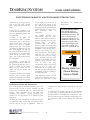
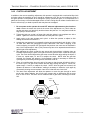
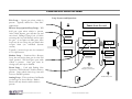
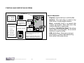
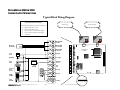
DOORKING SYSTEMS
access control solutions™
PREVENTATIVE MAINTENANCE
GUIDE
GATE OPERATOR SYSTEMS
INTRODUCTION:
• DoorKing Information
GATE SAFETY:
• Entrapment Protection Requirements
• Resetting an Alarm Condition
GATE OPERATORS:
• General Guidelines
• Preventative Maintenance and Adjustments
Swing Gate Operators
Slide Gate Operators
Parking Gate Operators
Loop Detectors
©DoorKing, 2004
updated 07/12/05
DOORKING SYSTEMS
ACCESS CONTROL SOLUTIONS . . .
access control solutions
2
Preventative Maintenance Guide
DOORKING SYSTEMS
access control solutions
INTRODUCTION: DoorKing is family owned and operated, providing quality products since 1948. We
maintain careful control of all aspects in the design and manufacturing of our systems. All engineering
and design work is performed at our main facility in California. We also manufacture our electronic
control circuit boards, and manufacture all of our Vehicular Gate Operators and Telephone Entry
Systems at this facility.
DoorKing products are available through our network of Dealers and Distributors. We provide factory
training programs, and regional training seminars to help our Dealers keep up to date on products and
technical information. In addition to our Dealers and Distributors, DoorKing has several regional
offices to help provide local contact for our valued clients:
DoorKing East
Ed Curry
Vineland, NJ
Ph: 858-691-1100
Fx: 856-691-0001
DoorKing South
Dave Minner, George Hendrix
Woodstock, GA
Ph: 770-926-1526
Fx: 770-926-1594
DoorKing Southeast
Chuck Fink
Sebring, FL
Ph: 863-471-9339
Fx: 863-471-3837
DoorKing North
Larry Wanat
Elgin, IL
Ph: 847-888-4810
Fx: 847-888-4820
DoorKing Central
Jeff Marshall
Plano, TX
Ph: 972-612-4842
Fx: 972-612-0803
DoorKing West
Lamar Jackson
Cameron Park, CA
Ph: 530-676-8941
Fx: 530-676-9824
DoorKing Northwest
Dan Morris
Seattle, WA
Ph: 206-525-5595
Fx: 206-525-5704
DoorKing Southwest
Jac Whitmire
Phoenix, AZ
Ph: 480-413-2010
Fx: 480-413-2001
DoorKing So Central
Tony Thornton
Pearl, MS
Ph: 601-664-1199
Fx: 601-664-1193
DoorKing has also developed a Training Program for Property Management companies. This is
designed to teach maintenance personnel how to properly maintain their DoorKing systems. The
information provided will assist in the following areas:
Institute a Preventative Maintenance program for DoorKing systems.
Provide periodic maintenance and adjustment on DoorKing systems to help ensure safe and
proper operation
Educate maintenance personnel on how these systems should operate under normal conditions,
and how they react under Alarm or Entrapment conditions, Power Outage conditions, etc.
Instruct maintenance personnel on how to reset the system should an alarm or shutdown
condition exist.
Instruct maintenance personnel on what to look for when the gate system experiences
operational problems. This can help the Service Dealer when they are repairing the gate system.
This Preventative Maintenance Guide includes maintenance schedules for various models of DoorKing
Gate Operators. These should be posted in the shop area and a program should be established to ensure
that proper maintenance is performed on the Gate Operator System.
ACCESS CONTROL SOLUTIONS . . .
3
Preventative Maintenance Guide
DOORKING SYSTEMS
access control solutions
GATE OPERATOR SAFETY AND ENTRAPMENT PROTECTION
Compromising on gate and gate operator
safety can have tragic results. By Rick
Sedivy (excerpt from article dated Dec,
1996)
A few years ago, in Illinois, a six
year old child was pinned by a slide
gate at an apartment complex and
was suffocated.
According to the police, the
accidentoccurred when a resident
activated the gate to open with a
remore control device. As the gate
began to run open, two children
jumped on the gate. The resident
screamed fo the children to get off.
One child jumped off, but the
other was pinned between the gate
and the fence post. A police officer
stated that the gate had a safety
device, but it only worked during
the closing cycle.
In California, a young girl was
going to a friends house to baby sit.
She reached thgough the gate to
activate a switch on the inside.
When the gate started, she was
pulled into the gate pocket and
suffocated.
In Houston, an adult male reached
through a gate to activate a digital
keypad. His employer conveniently
had a hole cut through the gate just
so his employees could do this if
they were on the outside of the
gate. When the gentleman entered
the digital code, the gate started and
pulled him into the gate pocket.
The
gentleman
died
of
asphyxiation.
The incidents described here
(unfortunately, there are more)
disprove many outdated schools of
thought regarding gates and gate
operator safety.
To begin,
automated gates are just as
dangerous, and in fact maybe more
dangerous because fo entrapment
possibilities, in the opening cycle as
they are in the closing cycle. For
years, manufacturers and installers
addressed only safety concerns
when the gate was in the closing
cycle. Reversing edges are often
installed on the leading edge of a
slide gate, giving everyone a false
sense of safety, and many
manufacturers made no provisions
what so ever to sense gate
obstructions int eh opening cycle.
The fact is people are being injured
and killed by slide gates running in
the OPEN direction.
Gate Operating systems can be
made safe, but achieving this safety
requires the cooperation of the
manufacturer, the installer and
theEnd User!.
GATE WARNING SIGNS
Gate Warning Signs are
included with all DoorKing
vehicular gate operators. This
sign is a requirement for
compliance with the UL 325
Standard for Gate Safety. The
sign must be posted so that
people approaching the gate,
from inside or outside, can
clearly view and read the sign.
WARNING
Moving Gate Can
Cause Serious
Injury or Death
PEDESTRIAN GATES ARE IMPORTANT
One of the hazards of automated vehicular gates is that
everyone seems to want to use the vehicular gate and
traffic lane as a pedestrian walk way. This creates two
hazards.
First, pedestrians are in the traffic lane
competing with vehicles.
Second, automated gate
operators are not designed for use in pedestrian traffic
applications.
companies that design products specifically for this type
of use
A requirement for comliance with the UL 325 Standard
for Gate Safety, a separate pedestrian entrance must be
provided whenever a Vehicular Gate is Automated. This
must be separate from the traffic lane and provide entry
for pedestrian traffic without utilizing the Vehicular
Gates.
DoorKing does not manufacture any operator designed
for pedestrian traffic control and our operators must
never be used in this type of application. There are
ACCESS CONTROL SOLUTIONS . . .
4
Preventative Maintenance Guide
DOORKING SYSTEMS
access control solutions
GENERAL GATE OPERATOR SYSTEM GUIDELINES
DEFINING THE PROBLEM
Should a problem occur with the gate system, before turning off power to the operator, Inspect
the system - Gate Operator failures are often intermittent and difficult for the service dealer to trouble
shoot. By inspecting the gate operator and looking at the indicator lights on the circuit board, you
can help reduce the amount of time needed to repair the gate system.
Before resetting the system try to observe the gate failure - In many cases, the gate system may
have an intermittent problem. These often can be reset by cycling the power OFF then ON, putting the
gate back into operation. However, the intermittent problem may still exist. Try to observe the problem
and make a note on what you see during the gate failure prior to resetting the operator..
Give the system a visual inspection - Many common problems are the result of physical factors of the
installation.
•
Keep the area free of debris (mud, rocks, leaves, etc.). Make sure that no branches, or
bushes are interfering with the gate travel.
•
See if the gate will move freely by hand.
•
Make sure the system is properly grounded.
Keep Iron in good repair - If the gate has been hit it can be out of alignment and can result in
operational problems with the gate system. Make sure that all Standard maintenance is performed
on the operators, Proper lubrication for wheels, rollers, hinge bearings, chains, etc. Proper adjustment
on drive chain (min. 1” of sag per 10’ of gate length). Test all Entrapment Protection devices on a
regular basis. Do Not Compensate for a in disrepair by tightening down the clutch or reducing
gate reverse sensativities.
Keep a Log of Gate Problems or failures - A time consuming part of servicing a Gate System is
tracking down the problem. Try to keep a log of gate problems, and of what steps you have taken to
reset the gate system. If a service call is required, this can help the Service Technician in trouble shooting
the source of the problem.
ACCESS CONTROL SOLUTIONS . . .
5
Preventative Maintenance Guide
DOORKING SYSTEMS
access control solutions
GATE INSTALLATION
The physical installation and wiring of the operator is a critical factor in reliable gate operation. When
servicing a gate system, double check some of the installation factors to see if they may be the source of
the problem.
•
Location of the Operator - SLIDE GATE OPERATORS should be located within a couple of
inches of the gate, with the concrete pad beneath the entire operator. Do not hang the back edge
of the operator over the pad. Also, make sure the operator is mounted square to the gate and
that the chain runs straight through the operator.
SWING GATE OPERATORS must be located to provide proper arm geometry and smooth gate
movement. The Arms should rotate 180° when running from the Closed to the Open position.
•
Mounting the Operator - Make sure that the operator is securly mounted to the concrete pad.
There should be no movement of the operator on it’s mounts.
•
UL 325 related Devices - Proper installation of all related Entrapment Protection Devices will
significantly improve the gate system reliability. This includes any Reversing Edges on the gate
and all Photo Cell devices. Test all devices for proper operation.
TRACKING DOWN THE PROBLEM
Many gate system operational problems or failures can be difficult to track down. It is sometimes helpful
to isolate what area is causing the actual problem. With the new UL 325 requirements, Gate Operators
may also enter a “Shutdown” condition if the operator senses an obstruction. Please keep in mind how
Gate Operators will function and react due to the new UL 325 requirements:
UL 325 Related Functions - The updated UL 325 related functions affect how the gate operates.
These may result in a gate not responding to open or close commands, getting “Stuck” in the Open
or Closed position, or reversing during operation. Remember the following gate conditions:
Photo Cells, if connected to the UL terminals will Stop the Gate, not reverse the gate.
Soft Shutdown - If the gate senses an obstruction in either direction, it will reverse and
return to the Limit Position. If the gate is closing, it will reverse and return to the full open
position. IT WILL NOT TIME OUT AND CLOSE. It will Hold at the OPEN
position until an open command has been given to the gate (Loop, Remote, Keypad, etc.)
If the gate senses an obstruction, reverses and senses a 2nd obstruction, it will stop and enter
an Alarm or Hard Shutdown condition. The gate will not function until the gate is reset.
All access devices will be disabled, including the Phone Entry system, RF Control, Card
Readers, Keypads, etc. An Alarm Tone will sound for 5 minutes following a shutdown.
After 5 minutes, the Alarm Tone will beep every 5 seconds, indicating that the operator is
in a Hard Shutdown condition. Activate the Alarm Reset button (by Power Switch) or
cycle power OFF / ON to reset gate system.
On the following pages we provide some simple troubleshooting tips and common adjustments that
can help maintain proper operation for your system. When working on the system, keep notes on
what steps you have taken and what problems you observed. This will help the Service Technician
repair your system, should a service call be required.
ACCESS CONTROL SOLUTIONS . . .
6
Preventative Maintenance Guide
DOORKING SLIDE GATE OPERATORS, MODEL 9100 & 9150
9000 Series Slide Gate Operators:
♦
♦
Model 9050 ½ HP Limited Duty
Residential operator
Model 9070 ½ HP Light Duty
Residential / Light Commercial
Operator.
9100 Series Operators
♦
♦
Model 9100 ½ HP Continuous Duty
Commercial operator
Model 9150 ½ & 1 HP Continuous
Duty Commercial / Industrial
Operator.
9310 Series Operators
♦
♦
Advanced Limit Switch Design
Model 9310 ½ & 1 HP Continuous
Duty Commercial operator
Model 9200 1hp models Industrial
Op w/ limit switch design
♦
♦
♦
Continuous Duty Operation.
115, 230 vac single phase
208, 230 or 460 vac 3-phase
1
2
Open
Reverse
3
4
5
4602 CIRCUIT
BOARD
6
7
8
9
10
11
12
13
14
15
16
17
18
Gate Operator Control Board (typical)
ACCESS CONTROL SOLUTIONS . . .
7
Preventative Maintenance Guide
DOORKING SLIDE GATE OPERATORS, MODEL 9100 & 9150
IMPORTANT NOTICES
Vehicular gate systems provide convenience to their users and limit vehicular traffic onto your property.
These systems can produce high levels of force; therefore it is important that you are aware of possible
hazards associated with your gate operating system. These hazards may include pinch points, entrapment,
absence of controlled pedestrian access or traffic backup.
Be sure that the installer has instructed you on the proper operation of the gate and gate operator system.
Be sure that the installer has trained you about the basic functions of the required reversing systems
associated with your gate operating system and how to test them. These include reversing loops, inherent
reversing system, electric edges, photoelectric cells, or other external devices.
•
This Owner's Manual is your property. Keep it in a safe place for future reference.
•
Loops and loop detectors must be installed with this gate operator to prevent the gate from
closing on vehicular traffic.
•
The speed limit for vehicular traffic through the gate area is 5 MPH. Install speed bumps and
signs to keep vehicular traffic from speeding through the gate area. Failure to adhere to posted
speed limits can result in damage to the gate, gate operator, and to the vehicle.
•
Be sure that all residents are familiar with the proper use of the gate and gate operator. Be sure that
all residents are familiar with the possible hazards associated with the gate system.
•
Be sure that all warning signs are permanently installed on both sides of the gate in an area where
they are fully visible to traffic.
•
It is your responsibility to periodically check all reversing devices. If any of these devices are
observed to function improperly, remove the operator from service immediately and contact your
installing or servicing dealer.
•
Follow the recommended maintenance schedule.
•
Do not allow children to play in the area of the operator or to play with any gate-operating device.
•
Be sure that all activating devices are installed a minimum distance of 10 feet away from the gate
and gate operator, or in such a way that a person cannot touch the gate or gate operator while
using the activating device. If activating devices are installed in violation of these restrictions,
immediately remove the gate operator from service and contact your installing dealer.
•
To remove the gate operator from service, operate the gate to the full open position and then shut
off power to the operator at the service panel.
SPEED BUMP
HAZARD AREA
PEDESTRAINS
VEHICULAR
TRAFFIC
HAZARD AREA
SPEED BUMP
ACCESS CONTROL SOLUTIONS . . .
8
Preventative Maintenance Guide
DOORKING SLIDE GATE OPERATORS, MODEL 9100 & 9150
IMPORTANT SAFETY INSTRUCTIONS
WARNING - To reduce the risk of injury or death:
1. READ AND FOLLOW ALL INSTRUCTIONS.
2. Never let children operate or play with gate controls. Keep the remote control away
from children.
3. Always keep people and objects away from gate. NO ONE SHOULD CROSS THE
PATH OF THE MOVING GATE.
4. Test the operator monthly. The gate MUST reverse on contact with a rigid object or
stop or reverse when an object activates the non-contact sensors. After adjusting the
force or the limit of travel, retest the gate operator. Failure to adjust and retest the
gate operator properly can increase the risk of injury or death.
5. KEEP GATES PROPERLY MAINTAINED. Read the owner's manual. Have a
qualified service person make repairs to gate hardware.
6. The entrance is for vehicles only. Pedestrians must use separate entrance.
7. SAVE THESE INSTRUCTIONS!
4.1 POWER AND RESET SWITCHES
Open the power switch cover located on the side of the operator to access the MAIN POWER,
BACKUP POWER and the operator RESET switches (Figure 38).
•
•
•
The RESET switch is used to turn off
the entrapment alarm and to reset the
operator after a hard shutdown has
occurred.
The AC POWER toggle switch turns
power to the operator ON (toggle up) or
OFF (toggle down).
RESET
DC
POWER
The DC POWER toggle switch turns the
DC backup system power ON (toggle
up) or OFF (toggle down). This switch
is only installed on model 6100
operators with the DC backup system
installed.
AC
POWER
OFF
Figure 38
ACCESS CONTROL SOLUTIONS . . .
9
Preventative Maintenance Guide
DOORKING SLIDE GATE OPERATORS, MODEL 9100 & 9150
RESTRICTIONS AND WARNINGS
Install The Gate Operator Only If:
The operator is appropriate for the usage Class of the application and the gate is within the weight
and length limitations specified for the operator.
•
All openings of a horizontal slide gate are guarded or screened from the bottom of the gate to a
minimum of 4 feet (1.2 m) above the ground to prevent a 2 ¼ inch (57.15 mm) diameter sphere
from passing through the openings anywhere in the gate, and in that portion of the adjacent fence
that the gate covers in the open position.
•
All exposed pinch points are eliminated or guarded.
•
This operator is intended for installation only on slide gates used to control vehicular traffic.
Pedestrians must be provided with a separate access opening.
•
The gate must be installed in a location so that sufficient clearance is provided between the gate
and adjacent structures when opening and closing to reduce the risk of entrapment (see diagram).
Sliding gates should not open into public access areas.
•
The gate must be properly installed and work freely in both directions prior to the installation of
the gate operator. Do not over-tighten the operator clutch to compensate for a damaged gate.
•
Controls must be far enough from the gate so that the user is prevented from coming in contact
with the gate while operating the controls. Outdoor or easily accessible controls should have a
security feature to prevent unauthorized use.
•
All warning signs and placards must be installed where visible in the area of the gate.
Roadway
Gate Operator
All openings of a horizontal slide gate are guarded or screened from the
bottom of the gate to a minimum of four (4) feet (1.2 m) above the
ground to prevent a 2 1/4 inch (57.15 mm) diameter sphere from passing
through the openings anywhere in the gate and in that portion of the
adjacent fence that the gate covers in the open position. (ref. UL325
51.8.4.a.2)
Vehicular Gate
Fence
Sidewalk
Fence
Pedestrian
Access
•
Fence
The operator is
intended for installation
only on gates used for
vehicles. Pedestrians
must be supplied with a
seperate access
opening. (ref. UL325
51.8.4.b)
Gate
4 ft.
min
V-Track
Spacing must be such
that a 2 1/4 inch sphere
cannot pass through.
ACCESS CONTROL SOLUTIONS . . .
10
Preventative Maintenance Guide
DOORKING SLIDE GATE OPERATORS, MODEL 9100 & 9150
MAINTENANCE
Inspection and service of this gate operator by a qualified technician should be performed anytime a
malfunction is observed or suspected. High cycle usage may require more frequent service checks.
When servicing the gate operator, always check any secondary (external) reversing devices (loops,
photo eyes, etc.) for proper operation. If external reversing devices cannot be made operable, do not
place this operator in service until the malfunction can be identified and corrected.
Always check the inherent reversing system when performing any maintenance. If the inherent
reversing system cannot be made operable, remove this operator from service until the cause
of the malfunction is identified and corrected. Keeping this operator in service when the
inherent reversing system is malfunctioning creates a hazard for persons which can result in
serious injury or death should they become entrapped in the gate.
When servicing this gate operator, always turn power OFF!!
MONTHLY
INTERVAL
MAINTENANCE SCHEDULE
3
Alarm
12
Activate the primary (inherent) reverse system by blocking the gate
with a solid object. When the gate reverses, block the gate in the
opposite direction prior to the limit being reached. The entrapment
alarm should activate. Press the reset button to silence the alarm.
Drive Belt
Check for alignment, tightness and wear.
Chain
Check for sagging. Tighten if necessary.
Clutch
Check for proper slippage when an obstruction is encountered.
Fire Dept.
Check emergency vehicle access device for proper operation.
Gate
Inspect for damage. Check gate wheels, rollers and guides for wear
and grease if necessary.
Grease
Wheels and guide rollers if necessary.
Loop(s)
Check vehicular reverse and shadow loops for proper operation.
Primary Reverse
System
Check that the gate reverses on contact with an object in both the
opening and closing cycles. Adjust the clutch if necessary.
Pulleys
Check for alignment. Check setscrews.
Release
Check manual release for proper operation.
Secondary
Reverse Device
Complete
6
Check that secondary (external) reverse device(s) stop or reverse
the gate when activated.
Complete check of gate and gate operating system.
ACCESS CONTROL SOLUTIONS . . .
11
Preventative Maintenance Guide
TROUBLE SHOOTING - DOORKING SLIDE GATE OPERATORS, MODEL 9100 & 9150
Symptom
Items to check
Operator will not run
1. Be sure AC power switch is on.
2. Check if Power LED on circuit board is on, (indicates power to
control board.)
Operator will not run
Power LED is ON
1. Activate Card Reader, Transmitter or Phone Entry. Look at
circuit board inside Gate Operator and see if LED’s on the
“Keyswitch” or “Full Open” terminals light up when device is
activated. (indicates that the board is receiving open command).
2. Be sure the chain is not too tight. This may cause the operator
to stall. Chain should have approximately 1” of slack per 10’
of gate length.
Gate opens short distance,
then stops and reverses.
1. Check if the how much force is needed to stop the gate. It
should take around 40 pounds of force to stop gate. If the
gate can be stopped by less pressure the clutch or reverse
sensitivity may need adjustment. (See Following Page)
2. Check that the chain is not too tight.
3. While gate is moving, check that the counter LED sensors are
blinking (Slide Gate: bottom center of board, above shaft).
4. Turn power off manually roll gate open and closed to check if
there is any binding point, the gate should roll freely
throughout travel.
Gate opens but will
not close.
1. Check if circuit board LED’s on terminals 2, 4, 5 or 6 are on.
An input on any of these terminals will hold gate open.
2. Check red LED on Reverse and/or Exit Loop Detectors. If
on then loop is holding gate open. Also check Photo Eye
devices.
Gate starts to close
then reverses to open.
1.
2.
3.
4.
Loop Detector LED is
on continuously.
1. Activate reset switch on loop detector (for DoorKing
Model 9405, 9406 detectors this is a small push button next to
the large bank of dip switches. To reset press reset button.
Check for binding of gate at point of reverse.
Check if the how much force is needed to stop the gate.
Check counter LED’s
Check Loop Detector LED’s to see if loop is sensing the gate.
TROUBLE SHOOTING HINTS
If a malfunction occurs, isolate the problem to one of three areas: The Operator, The Keying
Devices (card reader, phone entry, etc.) or the Loop Detectors.
When placing a service call to the Authorized Dealer, relate what you found when following the
above steps.
ACCESS CONTROL SOLUTIONS . . .
12
Preventative Maintenance Guide
TROUBLE SHOOTING - DOORKING SLIDE GATE OPERATORS, MODEL 9100 & 9150
CHAIN ADJUSTMENT
1. Secure the chain brackets to each end of the gate so
that the brackets are level with the top chain
knockouts in the operator housing. Brackets should
be attached to the inside of the frame so that the
chain bolts, when attached, do not protrude beyond
the frame of the gate (figure 10).
2. Route the chain through the gate operator: over the
chain guide idlers and under the drive sprocket
(figure 12).
3. Slide each end of the chain through a chain stop
(optional). Chain stops are not required if the gate
has physical stops.
4. Attach the chain to the chain bolts using the master
links supplied, and then attach the chain bolts to the
chain brackets using the hardware supplied (figure
10). Make any adjustments to the chain length at this
time.
5. Adjust the chain bolts to tighten the chain. The chain
should sag a minimum of one (1) inch per 10 feet of
travel. Do not over tighten the chain. IMPORTANT!!
Be sure that the chain is parallel to the gate
(figure 11). Installing the chain in any other
manner will cause excessive noise, chain idler
wear and chain stretching.
6. Manually open the gate to the full open position and
secure the chain stop (if installed) to the chain so that
it is in contact with the operator housing.
7. Manually close the gate to the full closed position and
secure the chain stop (if installed) to the chain so that
it is in contact with the operator housing.
ACCESS CONTROL SOLUTIONS . . .
13
Figure 1
Figure 2
Preventative Maintenance Guide
TROUBLE SHOOTING - DOORKING SLIDE GATE OPERATORS, MODEL 9100 & 9150
Operator Adjustments
Frequency
High
Med-Hi
Med-Lo
Low
1 OFF, 2 OFF
1 OFF, 2 ON
1 ON, 2 OFF
1 ON, 2 ON
1
2
Frequency
Switches
Power LED
Reset Button
Press to reset Detector, or
when changing
Frequencies &/or Sensitivity
Operation Settings
Reset
Button
Fast Trak 1 OFF=Normal
1 ON = Fast Trak
Sensitivity
Low
Med-Lo
Med-Hi
High
2 OFF, 3 OFF
2 OFF, 3 ON
2 ON, 3 OFF
2 ON, 3 ON
Sensivity 4 OFF= Normal
Boost
4 ON = Boost
1
2
3
4
Detect LED
Solid Red - indicates vehicle presence, or that
detector is "Locked ON"
Flashing Red - Indicates that a failure occured in
Loop Circuit. If detector has automatically reset, this
will continue to flash showing that a fault had
occured.
RESET
Battery
POWER
AC
POWER
OFF
OFF
Detect LED
Sw 2
Sensitivity
Sw 3
Sw 4 = Sens
Boost
Decrease
Increase
Adjust Reverse
Sensitivity
on Control Board
Loosen
Clutch
Adjust
Jamb Nut
Lock
Unlock
Power Switch for
optional Battery
Back-up
Tighten
Clutch
1) Loosen Center
Hex Lock Screw
ACCESS CONTROL SOLUTIONS . . .
14
Figure 3
Preventative Maintenance Guide
TROUBLE SHOOTING - DOORKING SLIDE GATE OPERATORS, MODEL 9100 & 9150
3.4 INHERENT REVERSE ADJUSTMENT
This vehicular gate operator is equipped with an inherent (Type A) entrapment sensing system. This
system will sense an obstruction in either the opening or closing gate cycles and will cause the gate to
reverse direction should an obstruction be encountered. For this system to function correctly, the gate
must be properly installed and work freely in both directions. A good set of ball bearing wheels (or
rollers) is essential for proper slide gate operation.
3.4.1 REVERSE SENSITIVITY ADJUSTMENT
1. Make sure that the Automatic Limit setting has been completed (the gate has run at least 2
cycles since power was last turned ON)
2. Activate the gate operator by momentarily shorting terminal 4 and 18 with a 1-foot piece of
18 AWG wire.
3. While the gate is running, slowly rotate the reverse sensitivity potentiometer clockwise until
the gate reverses travel, then back off 1/8 turn counter clockwise. (Rotating the sensitivity
adjustment clockwise INCREASES the reverse sensitivity. Rotating this adjustment
counter-clockwise DECREASES the reverse sensitivity.) NOTE: After the gate has
reversed, the operator will assume a "soft shutdown" making it necessary to initiate the
cycle again by momentarily shorting across terminals 4 and 18 as in step 1.
4. Operate the gate a few times to be sure that it cycles completely.
5. Test the gate in both the Opening and Closing cycles. Place an immobile object along the
path of the gate so that the gate will strike it while the gate is in motion. The gate must
reverse direction after striking the object. If it does not, increase the reverse sensitivity by
turning the potentiometer 1/8 turn clockwise, then repeat this test.
6. You may have to repeat step 2 several times to find the correct sensitivity adjustment.
DECREASE
INCREASE
Figure 4
ACCESS CONTROL SOLUTIONS . . .
15
Preventative Maintenance Guide
TROUBLE SHOOTING - DOORKING SLIDE GATE OPERATORS, MODEL 9100 & 9150
3.4.2 CLUTCH ADJUSTMENT
In addition to the reverse sensitivity adjustment, this operator is equipped with a mechanical slip clutch
to further reduce the possibility of injury should an entrapment occur. Do not over tighten the clutch in
this gate operator to compensate for a damaged or poorly constructed gate, or to compensate for a
gate that is too heavy or that has damaged wheels or rollers. Doing this can create a hazard which can
result in serious injury or death to persons who may become entrapped.
1. Be sure power to the operator is turned OFF whenever adjustments to the clutch are
made. Loosen the center lock screw in the center of the adjustment nut. (This is either an
an allen set screw or a large bolt), and then loosen the jamb nut. You may have to hold the
large pulley to loosen this nut.
2. Tighten the jamb nut so that it is finger tight, and then tighten it one complete turn with a
wrench. Tighten the center hex lock screw to lock the jamb nut in place.
3. Apply power to the gate operator and cycle it to allow the operator to adjust its limit
settings as described in section 3.3.
4. Activate the gate operator by momentarily shorting across terminals 4 and 18 with a 1-foot
18 AWG wire. When the gate begins to open, determine if the clutch is slipping. If the
clutch is slipping, turn power OFF and tighten the jamb nut one more turn as described in
step 2, then repeat steps 3 and 4 (This process may have to be repeated several times to
get the right clutch adjustment).
5. After adjusting the clutch so that the gate opens and closes without it slipping, place an
immobile object along the path of the gate so that the gate will strike it while in the open
cycle. The clutch should slip and the gate must reverse direction after striking the object. If
it does not, repeat steps 1-3 and 5 to readjust the clutch. NOTE: After the gate has
reversed, the operator will assume a "soft shutdown" making it necessary to initiate the
cycle again by momentarily shorting across terminals 4 and 18.
6. Place an immobile object along the path of the gate so that the gate will strike it while in
the close cycle. The gate must reverse direction after striking the object. If it does not,
repeat steps 1-3 and 6 to readjust the clutch. NOTE: After the gate has reversed, the
operator will assume a "soft shutdown" making it necessary to initiate the cycle again by
momentarily shorting across terminals 4 and 18 to initiate the auto close timer.
7. The ideal clutch adjustment will allow the operator to move the gate through its entire
travel cycle without slipping, but will slip upon contact with an obstruction with no more
than 75 Lbs of force. This force can be measured with a gate scale, DoorKing P/N 2600225.
Loosen
Clutch
Lock
Unlock
Jamb Nut
Tighten
Clutch
Center Hex
Lock Screw
Figure 5
ACCESS CONTROL SOLUTIONS . . .
16
Preventative Maintenance Guide
TROUBLE SHOOTING - DOORKING SLIDE GATE OPERATORS, MODEL 9100 & 9150
ACCESS CONTROL SOLUTIONS . . .
17
Preventative Maintenance Guide
LOOP DETECTION SYSTEMS
Loop Layouts and Operation:
Exit Loop - Opens gate when vehicle is
present. Typically utilized for “Free Exit”
applications.
Loop Detectors
THREE LANE LAYOUT
Reverse Loop (optional Stop Loop) - Will
hold gate open when vehicle is present.
After vehicle departs, gate will time out and
run closed. During Closing Cycle, a Vehicle
activating this loop will Reverse and re-open
the gate. As an option on Slide gates, these
loops may be set to Stop the gate rather than
re-open them (see Advanced Systems
section).
Exit
Reverse
Typically, 2 reverse loops may be connected
to 1 Loop Detector.
Reverse
Reverse
Shadow
Down
Shadow Loop - Functions like a Reverse
Loop, but only active when gate is at the Full
Open position. Will hold gate open while
vehicle is present. Once gate starts its
closing cycle, this loop is disabled.
Arming
Down Loop - Used with Parking Gate
Operators. Will hold arm UP while vehicle is
present. Once vehicle clears loop, Arm will
Lower to DOWN position.
Visitor Entry and
Emergency Access Lane
Resident Entry Lane
Arming Loop - This is tied into Card Reader
or other type of Access Device. Reader
Device will only function while vehicle is
present.
ACCESS CONTROL SOLUTIONS . . .
18
Preventative Maintenance Guide
TESTING LOOP DETECTION SY STEMS
Frequency
High
Med-Hi
Med-Lo
Low
1 OFF, 2 OFF
1 OFF, 2 ON
1 ON, 2 OFF
1 ON, 2 ON
Detector Adjustments:
1
2
Frequency
Switches
Frequency: Separate each loop to avoid CrossTalk
Sensitivity: How much change is needed in Loop
Field to detect. Can affect height of detection.
Power LED
Reset Button
Press to reset Detector, or
when changing Frequencies
&/or Sensitivity
Reset
Button
Operation Settings
Fast Trak 1 OFF=Normal
1 ON = Fast Trak
Sensitivity
Low
Med-Lo
Med-Hi
High
2 OFF, 3 OFF
2 OFF, 3 ON
2 ON, 3 OFF
2 ON, 3 ON
Sensivity 4 OFF= Normal
Boost
4 ON = Boost
Detect LED
Sw 2
Sensitivity
Sw 3
Sw 4 = Sens
Boost
1
2
3
4
Detect LED
Solid Red - indicates vehicle presence, or that
detector is "Locked ON"
Flashing Red - Indicates that a failure occured in
Loop Circuit. If detector has automatically reset, this
will continue to flash showing that a fault had occured.
ACCESS CONTROL SOLUTIONS . . .
19
Boost: automatically boosts to an extermely high
sensitivity upon detection When vehicle leaves loop,
sensitivity drops back to original setting.
Fast Trak: USE WITH CAUTION! This will help
detector adjust as loop tuning drifts. This also will lower
Hold Time if a car parks over the loop
LED: Red for Detect. Flash count on start-up to
show frequency. Continuous blink indicates Loop
Fault occurred. Will continue till reset.
Preventative Maintenance Guide
DOORKING 9100 & 9150
SLIDE GATE OPERATORS
Typical Block Wiring Diagram
UL 325 Standard for Safety:
Secondary Entrapment Protection Devices:
Open Cycle Photo Cell
Close Cycle Photo Cell
Open Cycle Contact Sensor Edge
Close Cycle Contact Sensor Edge
Common
Reverse Loop
Exit Loop
1
Open
2
3
4602 CIRCUIT
BOARD
4
5
6
7
8
9
10
11
12
13
14
15
16
17
18
Programming Switches
Sw 1 = Direction
Sw 2 = Timer OFF/ON
ACCESS CONTROL SOLUTIONS . . .
20
Preventative Maintenance Guide
Reverse
DOORKING SLIDE GATE OPERATORS
LED Indicator Lights
A Steady Red Light on the Detector Board wi
Hold Gate Open.
A repeating Flashing Light will indicate a problem
with the Underground Loop.
Reverse Loop
Exit Loop
1
A Light Here will Open and
Hold Open Gate
Radio Receiver
Full Open Input
2
A Light Here will Hold Gate Opern
Full Open
5
14 Ft Open
6
Standard
Reverse
7
8
9
18
ACCESS CONTROL SOLUTIONS . . .
21
Preventative Maintenance Guide
Loosen
A Light Here will Open gate
14' and Hold Gate Open
4
Loosen
3
A Light Here will Open and
Hold Open Gate
TROUBLESHOOTING - DOORKING SWING GATE OPERATORS
Model 6100 1/2 hp Commercial Operator
♦
♦
♦
♦
Class I, II, III & IV.
14’ Gate Length, 500lb. max gate wt.
Bi-parting Master/Slave configuration available (single control board)
Battery Back-up convenience drive option.
Model 6300 1/2 hp & 1hp models
Commercial Op w/ advanced features
♦
♦
♦
♦
♦
♦
♦
Class I, II, III & IV.
1/2hp - 18’ Gate Length, 600lb. max
gate wt.
1hp - 22’ Gate length, 800lb. max gate
wt.
Bi-parting Master/Slave configuration
available (single control board)
Continuous Duty Operation.
Battery Back-up Convenience Drive
available.
115, 230 or 460 vac compatible (208
vac upon request)
ACCESS CONTROL SOLUTIONS . . .
22
Preventative Maintenance Guide
TROUBLESHOOTING - DOORKING SWING GATE OPERATORS
OPERATING INSTRUCTIONS
IMPORTANT SAFETY INSTRUCTIONS
WARNING - To reduce the risk of injury or death:
1.
2.
3.
4.
5.
6.
7.
8.
READ AND FOLLOW ALL INSTRUCTIONS.
Never let children operate or play with gate controls. Keep the remote control away
from children.
Always keep people and objects away from gate. NO ONE SHOULD CROSS THE
PATH OF THE MOVING GATE.
Test the operator monthly. The gate MUST reverse on contact with a rigid object or
stop or reverse when an object activates the non-contact sensors. After adjusting the
force or the limit of travel, retest the gate operator. Failure to adjust and retest the
gate operator properly can increase the risk of injury or death.
Use the emergency release only when the gate is not moving and power has been
shut-off.
KEEP GATES PROPERLY MAINTAINED. Read the owner's manual. Have a
qualified service person make repairs to gate hardware.
The entrance is for vehicles only. Pedestrians must use separate entrance.
SAVE THESE INSTRUCTIONS.
4.1 POWER AND RESET SWITCHES
Open the power switch cover located on the side of the operator to access the MAIN POWER,
BACKUP POWER and the operator RESET switches (Figure 38).
The RESET switch is used to turn off the
entrapment alarm and to reset the
operator after a hard shutdown has
occurred.
•
The AC POWER toggle switch turns
power to the operator ON (toggle up) or
OFF (toggle down).
•
The DC POWER toggle switch turns the
DC backup system power ON (toggle up)
or OFF (toggle down). This switch is only
installed on model 6100 operators with the
DC backup system installed.
RESET
•
DC
POWER
AC
POWER
OFF
OFF
Figure 38
ACCESS CONTROL SOLUTIONS . . .
23
Preventative Maintenance Guide
TROUBLESHOOTING - DOORKING SWING GATE OPERATORS
MAINTENANCE
Inspection and service of this gate operator by a qualified technician should be performed anytime a
malfunction is observed or suspected. High cycle usage may require more frequent service checks.
When servicing the gate operator, always check any secondary (external) reversing devices (loops,
photo eyes, etc.) for proper operation. If external reversing devices cannot be made operable, do not
place this operator in service until the malfunction can be identified and corrected.
Always check the inherent reversing system when performing any maintenance. If the inherent
reversing system cannot be made operable, remove this operator from service until the cause
of the malfunction is identified and corrected. Keeping this operator in service when the
inherent reversing system is malfunctioning creates a hazard for persons which can result in
serious injury or death should they become entrapped in the gate.
When servicing this gate operator, always turn power OFF!!
MONTHLY
INTERVAL
MAINTENANCE SCHEDULE
3
Alarm
Activate the primary (inherent) reverse system by blocking the gate
with a solid object. When the gate reverses, block the gate in the
opposite direction prior to the limit being reached. The entrapment
alarm should activate. Press the reset button to silence the alarm.
Arms
Check set screws and nuts. Check bushings for wear.
Backup System
If operator is equipped with option DC backup system, check to be
sure the system opens the gate upon loss of AC power.
Batteries
If operator is equipped with optional DC backup system, check the
batteries for any leakage or loose connections. Batteries should be
replaced every two years.
Drive Belt
Check for alignment, tightness and wear.
Fire Dept.
Check emergency vehicle access device for proper operation.
Gate
Inspect for damage. Check gate hinges for wear and grease if
necessary.
Gear
Inspect for wear. Grease if necessary. Use only EP Molybdenum
Disulfide (Moly D) grease (DoorKing P/N 2600-770).
Grease
Primary Reverse
System
Check that the gate reverses on contact with an object in both the
opening and closing cycles. Adjust the clutch if necessary.
Check vehicular reverse and shadow loops for proper operation.
Release
Check manual release for proper operation.
Worm Gear
Complete
12
Main shaft zert fitting.
Loop(s)
Secondary
Reverse Device
6
Check secondary (external) reverse device(s) stop or reverse the
gate when activated.
Inspect for wear and proper alignment.
Complete check of gate and gate operating system.
ACCESS CONTROL SOLUTIONS . . .
24
Preventative Maintenance Guide
TROUBLESHOOTING - DOORKING SWING GATE OPERATORS
Symptom
Operator will not run
Items to check
1. Be sure AC power switch is on.
2. Check if Power LED on circuit board is on.
Operator will not run
Power LED is ON
1. Activate Card Reader, Transmitter or Phone Entry. Look at
circuit board inside Gate Operator and see if LED’s on
terminals 11 or 12 light up when device is activated.
2. Using a wire jumper, jump between terminals 11 & 20, gate
should open.
Gate opens short distance,
then stops and reverses.
1. Check if the how much force is needed to stop the gate. It
should take around 40 pounds of force to stop gate. If the
gate can be stopped by less pressure the clutch may need
adjustment. (See Following Page)
2. While gate is moving, Check that the pulse counter LED
sensor is blinking at terminal #9 (on bi-parting gates both
counters must be blinking, terminals 9 & 10).
3. Turn OFF power and unlock the manual release and check
that the gate swings freely and that the hinges do not bind.
Gate opens but will
not close.
1. Check if circuit board LED on terminals 11, 12 or 15 are on.
If so, some device may be holding gate open.
2. Check red LED on Reverse and Exit Loop Detectors. If on
then loop is holding gate open.
Gate starts to close
then reverses to open.
1.
2.
3.
4.
Loop Detector LED is
on continuously.
1. Activate reset switch on loop detector (for DoorKing
Model 9405, 9406 detectors this is a small push button next
to the large bank of dip switches. To reset press reset
button.
Check for binding of gate at point of reverse.
Check if the how much force is needed to stop the gate.
Check counter LED’s
Check Loop Detector LED’s to see if loop is sensing the
gate.
TROUBLE SHOOTING HINTS
If a malfunction occurs, isolate the problem to one of three areas: The Operator, The Keying
Devices (card reader, phone entry, etc.) or the Loop Detectors.
When placing a service call to the Authorized Dealer, relate what you found when following
the above steps.
ACCESS CONTROL SOLUTIONS . . .
25
Preventative Maintenance Guide
TROUBLESHOOTING - DOORKING SWING GATE OPERATORS
Operator Adjustments
Clutch
Adjustment
Jamb Nuts
++
Magnetic Limit Counter.
"Credit Card gap"
between sensor and
magnetic ring
Power Switch
and Alarm Reset
Button
Lubricate Worm Gear
using "Moly-D" Grease
++
Grease Zert Fitting
on Main Bearing
ACCESS CONTROL SOLUTIONS . . .
Loosen nuts (4) to
adjust belt tension
26
Preventative Maintenance Guide
TROUBLESHOOTING - DOORKING SWING GATE OPERATORS
TESTING LOOP DETECTION SY STEMS
Frequency
High
Med-Hi
Med-Lo
Low
1 OFF, 2 OFF
1 OFF, 2 ON
1 ON, 2 OFF
1 ON, 2 ON
Detector Adjustments:
1
2
Frequency
Switches
Frequency:
CrossTalk
Power LED
Sensitivity: How much change is needed in
Loop Field to detect. Can affect height of
detection.
Reset Button
Press to reset Detector, or
when changing Frequencies
&/or Sensitivity
Reset
Button
Operation Settings
Fast Trak 1 OFF=Normal
1 ON = Fast Trak
Low
Med-Lo
Med-Hi
High
2 OFF, 3 OFF
2 OFF, 3 ON
2 ON, 3 OFF
2 ON, 3 ON
Sensivity 4 OFF= Normal
Boost
4 ON = Boost
Detect LED
Sw 2
Sensitivity
Sw 3
Sw 4 = Sens
Boost
Sensitivity
1
2
3
4
Detect LED
Solid Red - indicates vehicle presence, or that
detector is "Locked ON"
Flashing Red - Indicates that a failure occured in
Loop Circuit. If detector has automatically reset, this
will continue to flash showing that a fault had occured.
ACCESS CONTROL SOLUTIONS . . .
Separate each loop to avoid
27
Boost: automatically boosts to an extermely high
sensitivity upon detection When vehicle leaves
loop, sensitivity drops back to original setting.
Fast Trak: USE WITH CAUTION! This will
help detector adjust as loop tuning drifts. This also
will lower Hold Time if a car parks over the loop
LED: Red for Detect. Flash count on start-up to
show frequency. Continuous blink indicates Loop
Fault occurred. Will continue till reset.
Preventative Maintenance Guide
TROUBLESHOOTING - DOORKING SWING GATE OPERATORS
3.4 ENTRAPMENT SENSING SYSTEM
This vehicular gate operator is equipped with an inherent adjustable clutch (Type C) that is used as the
primary entrapment sensing system. The clutch will slip upon sensing an obstruction in either the
opening or closing gate cycle and will cause the gate operator to reverse direction should an
obstruction be encountered. For this system to function correctly, the gate must be properly installed
and work freely in both directions. A good set of roller bearing hinges is essential for proper swing
gate operation.
3.4.1 CLUTCH ADJUSTMENT
1. Be sure power to the operator is turned OFF whenever adjustments to the clutch are being
made. Loosen the upper jamb nut to "un-lock" the lower jamb nut then loosen the lower
jamb nut. (See figure 36 on the preceding page)
2. Manually move the gate so that it is positioned approximately half way open.
3. Tighten the lower jamb nut so that it is finger tight then tighten it one turn with a wrench.
Re-tighten the upper jamb nut.
4. Apply power to the gate operator and momentarily short across terminals 11 and 20 with a
1-foot piece of 18 AWG wire. When the gate begins to open, determine if the clutch is
slipping. If the clutch is slipping, turn power OFF and tighten the lower jamb nut one more
turn. This process may have to be repeated several times to get the right clutch
adjustment. Always start the gate from the half open position when adjusting the clutch.
5. After adjusting the clutch so that the gate opens and closes without it slipping, obstruct the
gate while it is in the opening cycle. The clutch should slip with no more than 40 Lbs of
force for approximately 2 seconds, and then the operator should reverse the direction of
travel of the gate. If the clutch does not slip, it is too tight. Repeat step 4 and re-adjust the
clutch. NOTE: After the gate has reversed, the operator will be in a "soft shutdown"
making it necessary to initiate the cycle again by momentarily shorting across terminals 11
and 20.
6. Repeat step 5, only this time obstruct the gate while it is in the closing cycle. The clutch
should slip with no more than 40 Lbs of force for approximately 2 seconds, and then the
operator should reverse the direction of travel of the gate. If the clutch does not slip, it is
too tight. Repeat step 4 and re-adjust the clutch. NOTE: After the gate has reversed, the
operator will be in a "soft shutdown" making it necessary to initiate the cycle again by
momentarily shorting across terminals 11 and 20.
7. The ideal clutch adjustment will allow the operator to move the gate through its entire
travel cycle without slipping, but will slip upon contact with an obstruction with no more
than 40 Lbs of force. This force can be measured with a gate scale, DoorKing P/N 2600225.
JAMB NUTS
ACCESS CONTROL SOLUTIONS . . .
28
Preventative Maintenance Guide
DOORKING SWING GATE OPERATORS
Typical Block Wiring Diagram
7
11
12
13
14
Wiring Color Code
_____________
15 _______________
_____________
16 _______________
_____________
17 _______________
_____________
18 _______________
_____________
19/20 ____________
Power
MicroPLUS
RF Receiver
Shadow Loop
Exit Loop
Reverse Loop
Radio Receiver
24 VAC power
7
Relay
Common
1
2
11
Full Open
12
Full Open
13
Open Only 3-button
Fire
Dept
4
CLOSE
Reverse Loop
Telephone
Entry
Systems
14
Close Only 3-button
15
Std Reverse
or
Shadow
9
10
11
12
1
16
Relay
14
15
Relay
16
8
1
17
Reverse
17
O
N
18
18
Card
Readers
O
N
13
Mag Lock
Digital
Keypad
Open
3 Button
Control
7
8
STOP
Photocell
4502 CIRCUIT
BOARD
5
6
OPEN
Keyswitch
Push
Button
3
19
8
20
19
Common
20
Common
To Terminals 20 & 15 for
Shadow Loop
SW 1
#4 Close Timer ON / OFF
#7 Bi-parting (OFF)
Single gate (ON)
SW 2
#1 Direction Master
#2 Direction Slave
Aux Terminals
#7 Photo Beam (Stops
gate in either direction)
#8 Photo Beam Common
(see manual for options)
ACCESS CONTROL SOLUTIONS . . .
29
Preventative Maintenance Guide
Shadow Loop
DOORKING SWING GATE OPERATORS
LED Indicator Lights
Exit Loop
Reverse Loop
1
2
7
3
4
4502 CIRCUIT
BOARD
5
6
11
Full Open
12
Full Open
7
8
A Light Here will Open and
Hold Open Gate
9
Open
A Light Here will Open and
Hold Open Gate
10
11
13
12
13
14
14
15
15
Standard
Reverse
16
17
Reverse
A Light Here will Hold Gate Opern
18
16
19
20
17
To Terminals 20 & 15 for
Shadow Loop
(see manual for options)
18
A Steady Red Light on the Detector Board
will Hold Gate Open.
19
20
ACCESS CONTROL SOLUTIONS . . .
A repeating Flashing Light will indicate a
problem with the Underground Loop.
30
Preventative Maintenance Guide
TROUBLE SHOOTING - DOORKING BARRIER ARM OPERATORS
Model 1601 - Single Arm: 14’ wooden Arm, 14’ Aluminum Arm, 10’ Plastic Arm
Model 1602 - Wishbone Arm: 20 Wooden 3-piece Arm
•
Electronic Limit Settings (no mechanical limit switches required).
•
ERD - Reversing mechanism
obstruction while arm is closing.
•
Automatic Close Timer (1 – 23 seconds) can
be used either separately or in conjunction with
DOWN Loop.
•
Plug-in Loop Detectors – ports for UP loop
and for DOWN or Reverse loop.
•
Gate Arm Speed Controls - The 1602 utilizes
a specially geared drive mechanism to provide
smooth gate movement even with the heavy 3piece arm. The Arm opens in approx. 5
seconds. Closing and reversing actions are
delayed to eliminate harmful whipping action in
the arm movement.
•
Gate Tracker - Service and Operational information can be transmitted, through a
Tracker Board, to the Transaction buffer of a DoorKing PC Programmable system. This
can also provide a dry relay contact when the gate encounters an obstruction.
•
Optional Battery Back-up drive automatically or on command.
•
Optional Heater and Fan kit for extreme environments.
•
Reinforced Operator Cabinet - The operator housing has been enlarged and reinforced
to provide a more stable platform for the gate operation. In addition, the mounting of the
gearbox and motor assembly has been reinforced.
ACCESS CONTROL SOLUTIONS . . .
senses
upon loss of primary power gate can open
31
Preventative Maintenance Guide
TROUBLE SHOOTING - DOORKING BARRIER ARM OPERATORS
The switch settings and adjustments in this chapter should be made after your installation and wiring to
the operator(s) is complete. Whenever any of the programming switches on the circuit board are
changed, power must be shut-off, and then turned back on for the new setting to take effect.
3.1 CIRCUIT BOARD ADJUSTMENTS
Set the DIP-switches on the circuit board to the desired setting. See switch-setting charts in
section 3.2.
•
Auto close timer (when turned on) can be set from 1 second (full counter clockwise) to
approximately 23 seconds (full clockwise).
•
Rotate the ERD potentiometer clockwise to increase sensitivity, counter clockwise to decrease
sensitivity.
•
Dry contact relay contacts (terminals 12-13) can be set for Normally Open (NO) or Normally
Closed (NC) operation by placing the relay shorting bar on the NO or NC pins respectively.
•
Power LED indicates that low voltage power is applied to the circuit board. The input LEDs
should be OFF and will only illuminate when the input is activated.
•
Limit LEDs will be ON when the arm is in the respective position.
•
Tracker and COMM LEDs indicate data communication to the Tracker board.
Tracker
Comm LED's
•
Time Delay
UP Limit LED
DOWN Limit LED
Programming
Switches
UP Loop Port
Gate Tracker
Data Terminals
Power LED
Reverse Sens LED
Reverse Sens Adj
DOWN Loop Port
Input LED's
Earth Ground
1
2
3
4
5
6
7
8
Relay Contact
Shorting Bar
9 10 11 12 13 14
Figure 6
ACCESS CONTROL SOLUTIONS . . .
32
Preventative Maintenance Guide
TROUBLE SHOOTING - DOORKING BARRIER ARM OPERATORS
3.4 REVERSE SENSITIVITY ADJUSTMENT
The barrier gate operator is equipped with an Electronic Reversing Device (ERD) which will cause the
barrier arm to reverse direction of travel should an object be encountered during the down cycle. The
amount of force required for the arm to reverse direction is dependent on the setting of the reverse
sensitivity potentiometer. The ERD has no effect on the arm travel should an object be encountered
by the arm in the up direction. Follow the instructions below to adjust the ERD potentiometer.
The ERD will have to be adjusted after the arm has been installed on the barrier operator. Do not
adjust the ERD until after the arm has been installed per section 4.1.
1.
2.
3.
4.
5.
6.
Turn the AC power toggle switch to the ON position.
Place the control toggle switch to the UP position. The arm should rotate UP.
Momentarily press the control toggle switch to the DOWN position. This will cause the
arm to rotate down. CAUTION: Be sure that all persons and vehicles are clear of the
arm before pressing the down toggle switch!
While the arm is traveling in the down direction, rotate the reverse potentiometer
clockwise until the reverse LED illuminates. The arm will reverse travel at this time.
Rotate the reverse potentiometer 1/8 turn counter clockwise.
You may have to repeat the adjustment a few times to find a satisfactory setting.
The ERD in the barrier operator is not intended to replace external reversing devices such as loops,
photo electric eyes, or reversing edges. It is important that these devices be installed according to the
needs and requirements of your particular application.
DECREASE
INCREASE
REVERSE
SENSITIVITY
Figure 7
ACCESS CONTROL SOLUTIONS . . .
33
Preventative Maintenance Guide
TROUBLE SHOOTING - DOORKING BARRIER ARM OPERATORS
MAINTENANCE
MONTHLY SCHEDULE
INTERVAL
3
Arm
Check for cracks or weathering. Repair or replace as necessary.
Belt
Check for alignment, tightness and wear.
ERD
Check the electronic reversing device for proper operation.
Adjust sensitivity if necessary.
Fire Dept.
Check emergency vehicle access device(s) for proper operation.
Gearbox
Check oil level.
Linkages
Check internal linkages for wear. Inspect bushing for wear.
Loops
Check all external ground loops for proper operation.
Pulleys
Check set-screws for tightness.
Reversing
Devices
Check electric edges and photo-cells for proper operation.
Complete
Check
Perform a complete system check. Include all reversing devices,
loops, access system devices, Fire Dept. access devices, etc.
6
12
•
When servicing, place AC power switch to the OFF position. If the operator is equipped with a
battery back-up system, place the battery power switch to the OFF position.
•
Inspection and service should be performed anytime a malfunction is observed or suspected.
High cycle usage may require more frequent service checks.
•
Use only Shell OMALA 150 gear oil when adding or replacing gearbox oil. IMPORTANT:
Do not fill gearbox to top. Gearbox is full when oil completely covers inspection
window.
Always check external reversing devices (loops, photo-cells, etc.) when performing maintenance. If
reversing devices are not functional and cannot be placed in an operable state, DO NOT PLACE
OPERATOR IN SERVICE. If the operator is equipped with a battery back-up system, follow the steps
below to check the operation of this system.
CAUTION: Keep clear of the arm and all internal moving parts.
1. Prior to checking the battery back-up system, both the AC power switch and the battery
back-up switch should be in the ON position.
2. Place the AC power switch to the OFF position. The arm should rotate to the UP position
approximately two seconds after the AC power switch is shut off.
3. Turn the AC power switch to the ON position. The operator will resume normal operation.
ACCESS CONTROL SOLUTIONS . . .
34
Preventative Maintenance Guide
TROUBLE SHOOTING - DOORKING BARRIER ARM OPERATORS
Symptom
Items to check
Operator will not run
1. Be sure AC power switch is on.
2. Check if Power LED on circuit board is on.
Operator will not run
Power LED is ON
1. Activate Card Reader, Transmitter or Phone Entry. Look at
circuit board inside Gate Operator and see if red LED on
terminals 6 or 7 light up when device is activated.
2. Toggle the manual UP / DOWN switch. Gate should move
up then down.
Gate opens but will
not close.
1. Check if circuit board LED on terminals 6, 7, 9 are on.
If so, some device may be holding gate open.
2. Check red LED on Reverse and Exit Loop Detectors. If on
then loop is holding gate open.
3. If auto close timer is not used, check bank of dip switches.
Switch #7, close timer, should be OFF,
Switch #6, up input: OFF= up command only,
ON= key open, key close.
Switch #4, Down Loop, ON= close gate with loop.
Gate starts to close
then reverses to open.
1. Check ERD LED. If it flashes when gate is closing then
rotate the ERD sensitivity potentiometer counter clockwise
1/8 of a turn.
2. Check Loop Detector LED’s to see if loop is reversing the
gate.
Down input / down loop
will not close gate.
1. Check that switch #4 is in the ON position.
2. Down input must be activated then de-activated to close
gate.
Loop Detector LED is
on continuously.
1. Activate reset switch on loop detector (for DoorKing
Model 9405, 9406 detectors this is a small push button next
to the large bank of dip switches. To reset press reset
button.
TROUBLE SHOOTING HINTS
If a malfunction occurs, isolate the problem to one of three areas: The Operator, The Keying
Devices (card reader, phone entry, etc.) or the Loop Detectors.
When placing a service call to the Authorized Dealer, relate what you found when following
the above steps.
ACCESS CONTROL SOLUTIONS . . .
35
Preventative Maintenance Guide
DOORKING SYSTEMS
Troubleshooting Gate Systems
DOORKING BARRIER ARM OPERATORS
Quick Start Wiring
UP Loop
Wiring Color Code
Terminal
Color
Time Delay
Close
Programming Switches
Sw 4 ON = Down Loop
OFF = Reverse Loop
6
_____________
7
_____________
8
_____________
9
_____________
10
_____________
11
_____________
12
_____________
13
_____________
14
_____________
Sw 7 Timer Close OFF/ON
DOWN Loop
Programming Switches
Sw 1 ON = 1602 Model
OFF = 1601 Model
Reverse
Sensitivity
8
9
10 11 12 13 14
Low Voltage
Common
7
Enable UP
6
Momentary UP
5
Reverse Input
4
DOWN
Down Loop
3
UP /
UP Loop output
2
UP Input
1
6
7
8
9
10
11
14
UP
ON
Power
OFF
Auto
Down
OPENING
DEVICES
DOWN
Devices
Switch
Loop
Detector
Fire
Dept
ACCESS CONTROL SOLUTIONS . . .
36
Preventative Maintenance Guide
DOORKING SYSTEMS
Troubleshooting Gate Systems
DOORKING PARKING GATE OPERATORS
LED Indicator Lights
Time Delay
Close
Programming Switches
Sw 4 ON = Down Loop
OFF = Reverse Loop
Sw 7 Timer Close OFF/ON
Reverse
Sensitivity
UP
ON
Power
OFF
Enable UP
10 11 12 13 14
Momentary UP
9
Reverse Input
8
6
7
8
9
10
11
An LED here will Hold Arm UP
7
DOWN
Down Loop
6
An LED here will lower arm
immediately after is goes UP
5
UP /
UP Loop output
4
An LED here will Hold Arm UP
3
UP Input
2
An LED here will Hold Arm UP
Auto
Down
ACCESS CONTROL SOLUTIONS . . .
37
An LED here will hold arm UP
following first vehicle
1
Programming Switches
Sw 1 ON = 1602 Model
OFF = 1601 Model
Preventative Maintenance Guide