1
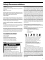
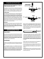
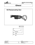
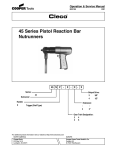
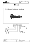
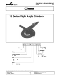
Operation & Service Manual
823132
2/01
136VGL Series Vertical Grinders
136
V G L
-
XXX
-
X X
X
Guard:
Series:
3
4
136
Type:
V
Vertical
3 In.
4 In.
Terminations:
Grinder:
Throttle Terminations:
L Lever
RPM:
135
180
For additional product information visit our website at http://www.clecotools.com
NORTH AMERICA
CooperTools
P.O. Box 1410
Lexington, SC 29071
3T
5T
3/8-24
5/8-11
Wheel Type:
Sander
D
Type 27
EUROPE
Cooper Power Tools GmbH & Co.
Postfach 30
D-73461 Westhausen
1
Safety Recommendations
!
WARNING
Do not operate without proper
wheel guard in place.
Impact resistant eye protection
must be worn while operating
or working near this tool.
Wear respirator where
necessary.
Grinding or other use of this tool may produce hazardous fumes and/
or dust. To avoid adverse health effects utilize adequate ventilation
and/or a respirator. Read the material safety data sheet of any
materials involved in the grinding process.
Cleco grinders are designed to operate on 90 psig (6.2 bar) max. air
pressure. If the tool is properly sized and applied, higher air pressure
is unnecessary. Excessive air pressure increases the loads and
stresses on the tool parts. Installation of a filter-regulator-lubricator in
the air supply line is highly recommended.
Never use the air hose for supporting, lifting, or lowering the tool. Use
a safety line or cable on the tool when working in elevated areas.
Before tool is connected to air supply, check throttle for proper
operation, i.e., throttle moves freely and returns to closed position.
Being careful not to endanger adjacent personnel, clear air hose of
accumulated dust and moisture. Use protective barriers where necessary — hot sparks can burn and/or ignite ignite flammable materials. Barriers also help reduce noise levels. Before removing tool from
2
Warning Label
WARNING
!
OVER
Repetitive work motions and/or vibration
can cause injury to hands and arms.
Use minimum hand grip force consistent with
proper control and safe operation.
Keep body and hands warm and dry.
Avoid anything that inhibits blood circulation.
Avoid continuous vibration exposure.
Keep wrists straight.
Avoid repeated bending of wrists and hands.
CAUTION
WARNING
Hearing protection is recommended in high noise
areas (above 85 dBA). Close proximity of other
tools, reflective surfaces, process noises, and
resonant structures can substantially contribute
to the sound level experienced by the user.
!
!
Personal hearing protection is
recommended when operating
or working near this tool.
Impact resistant eye protection
must be worn while operating
or working near this tool.
Made in USA
WARNING
202409
WARNING LABEL
869491
WARNING LABEL
869974
WARNING TAG
CLECO
!
3
• Do not wear clothing that may restrict movement, become
entangled or in any way interfere with the safe operation of
grinders.
2
• Gloves and other protective clothing should be worn as
required.
1
Hearing protection is recommended in high noise areas (above 85
dBA). Close proximity of additional tools, reflective surfaces, process
noises, and resonant structures can substantially contribute to the
sound level experienced by the operator. For additional information on
hearing protection, refer to Federal OSHA Regulations, 29 CFR,
Section 1910.95, Occupational Noise Exposure, and American National Standards Institute, ANSI S12.6, Hearing Protectors.
203011
WARNING LABEL
0
Personal hearing protection is
recommended when operating
or working near this tool.
The guard must be securely attached to the grinder with the bolt, nut
and lockwasher in place and torqued to 30 - 40 in. lbs.
6
CAUTION
NOTE: The grinder must be held so that the opening in the guard is
away from the operator.
5
!
The wheel guard is designed to prevent serious injury to the operator
in the event of wheel failure and must not be modified in any way. Any
wheel guard that is damaged or bent must be replaced.
4
For additional information on eye protection, refer to Federal OSHA
Regulations, 29 CFR, Section 1910.133, Eye and Face Protection,
and ANSI Z87.1, Occupational and Educational Eye and Face Protection. This standard is available from the American National Standards
Institute, Inc., 11 West 42nd Street, New York, NY 10036.
WARNING
Read Operating Instructions carefully. Follow
the Safety Recommendations for your safety
and the safety of others.
!
Do not remove this tag until
the operator of this tool has
read these safety precautions.
Always wear protective equipment and clothing.
service or changing accessories, make sure air line is shut off and
drained of air to prevent the tool from operating if the throttle is
accidently engaged. The use of a self-relieving valve for this purpose,
close to the tool or point of operation, is highly recommended.
Warning Label
For your safety and the safety of others, read and understand the
safety recommendations before operating any grinder.
The speed rating, warning tags and warning labels should be maintained or replaced for legibility in the event or damage. Speed rating,
warning tags, and warning labels are available from the manufacturer.
Before mounting a wheel, after all tool repairs, and whenever a grinder
is issued for use, check the free speed of the grinder with a tachometer
to make certain that the actual free speed at 90 psig (6.2 bar) does not
exceed the rated free speed stamped on the tool. Grinders in use on
the job must be similarly checked at least once every twenty hours of
operation, or once every week, whichever is more frequent. Checking
free speed after the removal of each worn wheel and before mounting
a new wheel is highly recommended.
!
WARNING
Fragments from an abrasive wheel
can cause serious injury or death.
Do not operate without proper
wheel guard in place.
INSPECT THE GRINDING WHEEL!
Check the maximum safe RPM marked on the wheel. Never use a
wheel rated below the actual tool speed. Inspect the wheel for
cracks or chips, water stains, or signs of abuse or improper storage.
Cracked, chipped or faulty grinding wheels are dangerous. They
must be destroyed rather than risk their use by someone who may not
notice that they are damaged.
Causes of abrasive wheel failures have been traced to such factors
as:
• Dropping, bumping, or abuse (careless handling of the grinder or
wheel)
• Improper mounting
Safety Recommendations
• Imbalance
• Improper shipment or storage
• Exposure to water, solvents, high humidity, freez ing and extreme
temperatures
• Mismatched speed ratings
• Age
Abrasive wheels known to have been subjected to any of the
above conditions can burst violently. Never operate a vertical
grinder without proper wheel guard in place.
CHECK FLANGE
Check the grinder spindle and driving flange for signs of damage or
abuse. The shape of a Type 27 wheel requires a special flange. The
spindle must not be bent and the threads should be free of any damage
that might keep an abrasive wheel and its mount from locating
centrally or seating properly against the driving flange.
ABRASIVE WHEEL MOUNTING & BEGINNING GRINDING OPERATION
The adapter nut should be tightened only enough to prevent slippage
and satisfactorily transfer the driving torque of the spindle to the wheel
through the adapter assembly. Do not over-tighten.
Before beginning operations or after mounting a wheel, the tool must
be run for one (1) minute in a protected enclosure to check the integrity
or the wheel. During this time or any other time, no one should stand
in front of or in line of the wheel. When starting work with a cold wheel,
apply it gradually to the workpiece until the wheel becomes warm.
DO NOT CONTINUE TO USE A GRINDER IF:
• It is not equipped with the proper wheel guard
• The speed rating of the wheel is less than the
speed of the grinder
• It starts to vibrate
• You sense any changes in tool speed or an
unusual increase in noise output that would
indicate the tool is running at excessive speed.
• You notice excessive end play in the spindle
• You hear any unusual sound from the grinder
RETURN THE TOOL TO THE TOOL CRIB FOR SERVICE IMMEDIATELY!
!
WARNING
Repetitive work motions and/or vibration
may cause injury to hands and arms.
Use minimum hand grip force consistent
with proper control and safe operation.
Keep body and hands warm and dry.
Avoid anything that inhibits blood circulation.
Avoid continuous vibration exposure.
Keep wrists straight.
Avoid repeated bending of wrists and hands.
Some individuals may be susceptible to disorders of the hands and
arms when performing tasks consisting of highly repetitive motions
and/or exposure to extended vibration. Cumulative trauma disorders
such as carpal tunnel syndrome and tendonitis may be caused or
aggravated by repetitious, forceful exertions of the hands and arms.
Vibration may contribute to a condition called Raynaud's Syndrome.
These disorders develop gradually over periods of weeks, months,
and years. It is presently unknown to what extent exposure to vibrations or repetitive motions may contribute to the disorders. Hereditary
factors, vasculatory or circulatory problems, exposure to cold and
dampness, diet, smoking and work practices are thought to contribute
to the conditions. Any tool operator should be aware of the following
warning signs and symptoms so that a problem can be addressed
before it becomes a debilitating injury.Any user suffering prolonged
symptoms of tingling, numbness, blanching of fingers, clumsiness or
weakened grip, nocturnal pain in the hand, or any other disorder of the
shoulders, arms, wrists, or fingers is advised to consult a physician.
If it is determined that the symptoms are job related or aggravated by
movements and postures dictated by the job design, it may be
necessary for the employer to take steps to prevent further occurrences. These steps might include, but are not limited to, repositioning
the workpiece or redesigning the workstation, reassigning workers to
other jobs, rotating jobs, changing work pace, and/or changing the type
of tool used so as to minimize stress on the operator. Some tasks may
require more than one type of tool to obtain the optimum operator/tool/
task relationship.
The following suggestions will help reduce or moderate the effects of
repetitive work motions and/or extended vibration exposure:
• Use a minimum hand grip force consistent with proper control and
safe operation
• Keep body and hands warm and dry (cold weather is reported to be
a major factor contributing to Raynaud's Syndrome)
• Avoid anything that inhibits blood circulation
—Smoking Tobacco (another contributing
factor)
—Cold Temperatures
—Certain Drugs
Avoid
Extension
OK
Neutral
Avoid
Flexion
Avoid
Radial Deviation
OK
Avoid
Neutral
Ulnar Deviation
• Tasks should be performed in such a manner that the
wrists are maintained in a neutral position, which is
not flexed, hyperextended, or turned side to side
• Stressful postures should be avoided — select a tool
appropriate for the job and work location
• Avoid highly repetitive movements of hands and
wrists, and continuous vibration exposure (after each
period of operation, exercise to increase blood circulation)
• Use quality abrasive wheels
• Keep tool well maintained and replace worn parts
Work gloves with vibration reducing liners and wrist supports are
available from some manufacturers of industrial work gloves. Tool
wraps and grips are also available from a number of different manufacturers. These gloves, wraps, and wrist supports are designed to
reduce and moderate the effects of extended vibration exposure and
repetitive wrist trauma. Since they vary widely in design, material,
thickness, vibration reduction, and wrist support qualities, it is recommended that the glove, tool wrap, or wrist support manufacturer be
consulted for items designed for your specific application. WARNING!
Proper fit of gloves is important. Improperly fitted gloves may
restrict blood flow to the fingers and can substantially reduce
grip strength.
3
Safety Recommendations
USE QUALITY ABRASIVE WHEELS
PROPER LUBRICATION
The primary source of vibration when using a portable grinder is an
abrasive wheel that is out of balance, out of round, untrue, or possibly
any combination of all three.
An automatic in-line filter-regulator-lubricator is recommended as it
increases tool life and keeps the tool in sustained operation. The inline lubricator should be regularly checked and filled with a good grade
of 10W machine oil. Proper adjustment of the in-line lubricator is
performed by placing a sheet of paper next to the exhaust ports and
holding the throttle open approximately 30 seconds. The lubricator is
properly set when a light stain of oil collects on the paper. Excessive
amounts of oil should be avoided.
The use of quality abrasive wheels which are well balanced, round, and
true is highly recommended as they have been found to significantly
reduce vibration. Some abrasive wheels lose their balance, roundness, and trueness as they wear from use. Because of the abusive
nature of the vibration caused by out of balance, out of round, and
untrue condition of some abrasive wheels, it is felt that these wheels
are more susceptible to failure. Excessive vibration may signal eminent wheel failure. (Out of balance abrasive wheel, caused by grinding
the wheel to a stop after the power has been shut off can result in
changes to the balance and shape of the wheel.) Be sure the grinding
wheel has stopped before setting the tool down. Set the tool in a tool
rest or tool holder when not in use.
STORAGE
In the event that it becomes necessary to store the tool for an
extended period of time (overnight, weekend, etc.), it should receive
a generous amount of lubrication at that time and run for several
seconds to distribute the oil before disconnecting from the air supply.
This will reduce the possibility of corrosion and displace any water
that may be trapped in the tool.
WIRE BRUSHES
Note: Water in the air system increases tool maintenance costs.
If a grinder is used for wire brushing applications the same problems
of balance, roundness, and trueness as experienced with abrasive
wheels prevail. Use quality wire brushes.
Proper repair procedures and the use of original Cleco service parts
and bearings rather than substitutes will return the tool to factory
specifications of precision and balance, and minimize vibration.
USE A PREVENTIVE MAINTENANCE PROGRAM
Tool abuse or poor maintenance procedures can amplify and contribute to the vibration produced by the abrasive wheel. A preventive
maintenance program featuring scheduled periodic inspections and
proper maintenance is the best way to assure safety in your portable
grinding operations. A well managed program can, for example, detect
such things as speed variations due to wear, flanges or spindles that
have been damaged from abuse, or bad bearings damaged by foreign
matter or lack of lubrication. Problems such as these can affect the
wheel trueness when the grinder is running and contribute to the
vibration. Rotor blades that are worn or chipped can lock up motor and
result in grinding wheel spinoff and should be replaced. Rotor blades
should be checked periodically and replaced if they measure less than
7/32" (5.5mm) at either end.
Replace if 3/16"
(4.7mm) or less
at either end.
4
For more information, see the latest edition of ANSI B186.1, Safety
Code for Portable Air Tools, and ANSI B7.1 Safety Requirements for
the Use, Care, and Protection of Abrasive Wheels available from the
American National Standards Institute, Inc., 11 West 42nd Street,
New York, NY 10036.
OPERATING INSTRUCTIONS
READ SAFETY RECOMMENDATIONS BEFORE OPERATING TOOL.
SELECT OR SAND
ROTOR COLLAR TO
THIS MEASUREMENT
PLUS .0015" (.038mm)
The136 Series Vertical Grinders are designed to operate on
90psig (6.2 bar) maximum air pressure, using a 5/16" hose
up to 8' in length. If additional length is required, the next
larger hose size may be connected to the 8' whip hose.
LUBRICATION
An automatic in-line filter-lubricator is recommended as it
increases tool life and keeps the tool in sustained operation.
The in-line lubricator should be regularly checked and filled
with a good grade of 10W machine oil. Proper adjustment
of the in-line lubricator is performed by placing a sheet of
paper next to the exhaust ports and holding the throttle open
approximately 30 seconds. The lubricator is properly set
when a light stain of oil collects on the paper. Excessive
amounts of oil should be avoided.
STORAGE
In the event that it becomes necessary to store the tool for
an extended period of time (overnight, weekend, etc.), it
should receive a generous amount of lubrication at that time
and run for several seconds to distribute the oil before
disconnecting from the air supply.
SERVICE INSTRUCTIONS
DISASSEMBLY
Unscrew the bearing retainer (left hand threads) from the
housing. This will allow the motor unit to be removed from the
front of the motor housing. Use a suitable driver to drive the
front rotor shaft out of the front rotor bearing. After removing
the rotor collar, cylinder and rotor blades, drive the rear rotor
shaft out of the rear rotor bearing.
FRONT
BEARING
PLATE
INNER RACE
OF BEARING
ROTOR
COLLAR
.OO15" (.038mm)
Clearance
FRONT
BEARING
PLATE
INNER RACE
OF BEARING
Next, slip on the front bearing plate and the front rotor
bearing. It is recommended that new rotor blades be
installed at each repair cycle. If not replaced, the used
ones must measure a minimum of 7/32" (5.5mm) at both
ends.Failure of these parts could cause damage to more
expensive components.
Replace if 3/16"
(4.7mm) or less
at either end.
Insert the rotor blades in the rotor and slip the cylinder
over the rotor. Assemble the rear rotor bearing into the rear
rotor shaft by lightly tapping on the inner race of the rear
rotor bearing until the rear bearing clamps against the rotor
preventing rotation. Tap the rear rotor shaft until the rotor
turns freely and will not touch either bearing plate under
axial load.
REASSEMBLY
The tool is reassembled in reverse order of disassembly with
special care being exercised when assembling the motor
unit.
To reassemble the motor unit, assemble the front rotor
bearing into the front bearing plate. Fit the rotor collar by
sanding on a flat sheet of sandpaper so it stands out .0015"
(.038mm) from the face of the front bearing plate when the
front rotor bearing is held toward the rear. Slip the rotor collar
(chamfered face first) over the front shaft of the rotor.
Slip the motor unit into the motor housing and tighten the
bearing retainer (left hand threads) securely.
After reassembly, place a few drops of 10W machine oil
in the air inlet before installing the hose. This will ensure
positive lubrication of all motor parts as soon as the air is
applied.
CAUTION: After the tool is reassembled, be sure to check
it for proper speed with a dependable tachometer before
returning it to service.
5
6
PARTS LIST — 136 SERIES VERTICAL GRINDER
Part No.
202105
202341
203011
203382
203384
412775
812165
834228
843422
843586
843587
847272
847411
847525
847528
847767
849905
867929
869445
869448
869449
869451
869457
869487
869488
869489
869491
869492
869495
869496
869499
869638
869664
869782
869855
869856
Name of Part
Toggle
Throttle Lever
Caution Tag (included in 203384, 869487)
4" Type 27 Wheel Guard
13,500 RPM Motor Housing (includes 869491, 203011, 834228)
Air Inlet Screen
Cylinder Pin (included in 869451)
Drive Screw (incluced in 203384, 869487)
Spindle End Nut
Back Up Pad
Back Up Pad Nut
"O"-Ring 5/8" X 3/4"
"O" -Ring 11/16 x 3/16"
Rotor Collar
Rotor Front Bearing
Throttle Valve Spring
3" Type 27 Wheel Guard
Air Inlet Bushing
Rotor Rear Bearing
Front Bearing Plate
Rotor Blade
Cylinder (includes 812165)
Throttle Lever Pin
18,000 RPM Motor Housing (includes 869491, 203011, 834228)
Throttle Pin Bushing
Throttle Valve
Instruction Tag (Included in 203384, 869487)
Muffler
Spindle Adaptor
Type 27 Wheel Driving Flange
Front Bearing Retainer
Rear Bearing Plate
Throttle Pin
Rotor
Spring
Pawl Pin
Qty.
1
1
1
1
1
1
1
2
1
1
1
1
1
1
1
1
1
1
1
1
4
1
1
1
1
1
1
1
1
1
1
1
1
1
1
1
The complete motor housing may be purchased as a subassembly using the Part No. listed
below:
136VGL-135
—
Part No. 201406
136VGL-180
—
Part No. 861829
The Lock -Off Lever may be purchased as a subassembly using Part No. 201411.
7
8
CooperTools
670 Industrial Drive
Lexington, SC 29072
Phone: (803) 359-1200
Fax: (803) 359-2013
www.clecotools.com