1
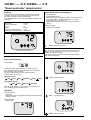
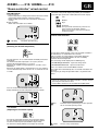
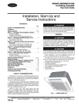
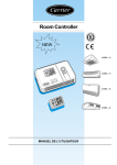
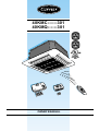
40KMC------301
40KMQ------301
OWNER’S MANUAL
IR Remote Control
“Room Controller”
“Zone Manager”
The unit can be used with infrared Remote Control, with the Carrier “Room
Controller” or “Zone Manager” remote control.
Carrier “Room controller” control instructions are contained in the present manual.
Infrared Remote and “Zone Manager” controls instructions are contained in the relevant
manuals.
The installation instructions for both the indoor and the outdoor unit are given in the
manuals for each unit.
Contents
Page
General information ....................................................................................
2
System description .....................................................................................
2
Unit LEDs and controls ...............................................................................
3
Periodical checks ........................................................................................
3
Optimum comfort and minimum power consumption .................................
4
Correct cleaning ..........................................................................................
4
Before a long shutdown period ..................................................................
4
“Room controller” general information and characteristics ............................
5
Unit protection devices ...............................................................................
5
“Room controller” wired control ..................................................................
6/7
Troubleshooting ..........................................................................................
8
ENGLISH
40KMC------310/ 40KMQ------310
Split system “Global cassette” indoor unit
GB - 1
40KMC------310/ 40KMQ------310
General information
Unit operation and maintenance
Read this instruction manual thoroughly before using the unit.
• This unit complies with UL 1995 directive (Usa and Canada).
• Check that the main power supply voltage and frequency are as
required for the unit; the power source must be sufficient to
operate all other appliances connected to the same line.
Also ensure that local building codes and NEC (National electrical
code) requirements have been followed for the main supply circuit.
• To avoid personal injury or damage to unit,do not service until all
power sources are shut down, locked out, and tagged out.
Failure to do so could result in personal injury or unit damage.
!
smell of burning) and call Carrier Service for further instructions.
• A routine maintenance should be carried out on the unit to check the
correct operation of the electric connections and protection devices.
• Extraordinary maintenance operations must be carried out by
specially trained personnel.
• Do not attempt to repair, move, modify or re-install the unit on your
own. To avoid electric shock or fire make sure these operations
are carried out by qualified personnel only.
• Contact the qualified service if one of the following events takes place:
- hot or damaged power supply cable;
- unusual noise during operation;
- frequent operation of the protection devices;
- unusual smell (such as smell of burning).
WARNING:
!
To prevent fire, explosion or injury, do not operate the unit near
dangerous substances or esposed to lighting equipment.
• All operation and maintenance manuals must be carefully looked
after and kept with the equipment, should the unit change owners.
• Check that local building codes and NEC (National electrical code)
requirements for the installation have been followed. In particular,
ensure that a properly sized and connected ground wire is in place.
• Only use the unit for factory approved applications: the unit
cannot be used in laundry premises.
• Do not use damaged equipment. In case of malfunction, turn the
unit OFF and disconnect the main supply.
• Disconnect the main power supply prior to any maintenance
operations or prior to handling any internal unit parts.
• The manufacturer declines any liability for damage resulting from
modifications or errors in the electrical or refrigerant connections,
made during the installation, or from improper use of this equipment.
This will invalidate the unit warranty conditions immediately.
• This unit will only work safely and correctly, if installed and tested
by qualified personnel.
• Do not open the remote control to avoid possible damage.
In case of malfunction contact a qualified service engineer.
• This unit contains moving parts. Ensure that these parts are kept
out of the reach of children.
• Maintain the room temperature at general comfort conditions,
especially when children, elderly or handicapped persons are present.
• In order to ensure correct use, the air conditioner must operate
within the temperature limits indicated in the “Operating Limits”
table, included in the Technical manual. Failure to observe these
limits may cause unit malfunction or water leakage.
• In order to avoid electric shock, fire or injury, stop the unit and
disconnect the safety switch in case of abnormal events (such as
WARNING:
Never operate unit without a filter or with grille removed. Damage
to the unit or personal injury may result.
!
WARNING:
If air filter is not replaced in the unit, dust and dirt gather in air
conditioner and operation becomes impaired.
• A mist or cloud of vapor may be emitted from the unit, when
switching from a cooling operation to a reverse cycle heating
operation. This will occur when the unit has been operating in
cooling mode for awhile and then is switched to heating. The
combination of the evaporated indoor coil condensate and the dry
room air, may result in a cloud of vapor being emitted from the
unit. There is no need for concern.
• Inspect equipment for damage during transport. In case of
damage file an immediate claim with the shipping company.
• Non-routine maintenance of the refrigerant circuit must only be
carried out by qualified personnel.
• All of the manufacturing and packaging materials used for
this appliance are biodegradable and recyclable.
• Dispose of the packaging material and of the remote control
batteries in accordance with local requirements.
• This equipment contains refrigerant that must be disposed of
correctly. When disposing of the unit at the end of its operational
life, take the unit to an authorised waste disposal centre, for
correct disposal procedures.
!
WARNING:
The unit must always be switched OFF using the Room
Controller. Do not switch OFF the split system by
disconnecting the electric power supply.
7
6
1 2
3
4
System description
B
A. Outdoor unit
B. Indoor unit
C. Room Controller
(if foreseen)
1.
2.
3.
4.
Air return
Air filters
Air supply
Operation indicator light
and receiver of remote
control signals (if foreseen)
5. Nameplate
6. Interconnecting tubing
7. Condensate drain (open)
GB - 2
A
C
5
40KMC------310/ 40KMQ------310
Unit warning lights and controls - Fault code
ENGLISH
P : Green LED
Q : Red LED
R : Yellow LED
S : Remote control
signal receiver
Indoor unit LEDs
Fault code
Information concerning indoor unit operation, timer status and
diagnostic is given by 3 LEDs located on the unit.
Once a failure occurs with the indoor unit in operation, the green
unit LED flashes at intervals of 0.5 seconds.
The fault code is deduced from the number of times the green
LED flashes, blocking unit operation.
Between one flash cycle and the next one, a pause of 5 seconds
elapses.
• THE GREEN LED (P) shows the following conditions:
- Fault codes (diagnostic);
- During normal operation, the LED is lit.
Once a failure occurs, the LED flashes at intervals of 0.5
seconds. The fault code is deduced from the number of times
the LED flashes. Between one flash cycle and the next a pause
of 5 seconds elapses.
• THE RED LED (Q) gives the following information:
- During normal operation, the LED is OFF;
- During defrost the LED is lit;
- During the test for wired connection, the LED flashes at 0.1
second intervals.
• THE YELLOW LED (R) shows the operation in timer mode.
During this operation the LED is lit.
If the timer mode is active and the unit is immediately
restarted after a stop, this LED flashes until a new signal is
sent to the unit.
In case the Room Controller is not working, obtain a qualified
service personnel.
Table IX: Fault code
Code
Description
3
Room air sensor fault
2
Condensate discharge pump
4
Indoor unit coil sensor fault
6*
Filter dirty
7
Outdoor unit failure
10
EEPROM corrupt
11
Card serial number damaged
12
Address / zone incomplete
13
14
Gas flow distributor corrupt
Outdoor air thermistor
* with enabled code
Table II: Periodical checks
Indoor unit
Clean air filter (2)
Clean drain pipe (2)
Outdoor unit
Clean outdoor coil from outside
Clean outdoor coil from inside (2)
Blow air over electric parts (2)
Check electric connection tightening (2)
Clean fan wheel (2)
Check fan tightening (2)
Clean drain pan (2)
Every month Every 4 months
•
Every year
(1)
•
Every month Every 4 months
•
Every year
•
•
•
•
•
•
For a good operation of the
air conditioner it is
recommended to carry out
checks and maintenance
as indicated.
Recommended
maintenance intervals may
vary depending on the
installation environment,
e.g. dusty zones, etc.
(1) Increase frequency in
dusty zones.
(2) Operations to be
carried out by qualified
service personnel.
Refer also to
“Installation Manual”.
GB - 3
40KMC------310/ 40KMQ------310
Optimum comfort... - Correct cleaning - Before a long shutdown period
Optimum comfort and minimum power
consumption
Correct cleaning
• Turn the unit OFF and switch the main supply OFF.
Keep room temperature at a comfortable level.
Use only a clean, damp cloth and a mild detergent.
Do not use flammable liquids, solvents or abrasive powders that
may result in damage to the panels.
Use only a dry cloth to clean the remote control.
Before a long shutdown period
Only open doors and windows when strictly necessary.
Ask to clean the filter and replace it in the unit.
12 h
When cooling, avoid direct sunlight in the room: if possible, draw
the curtains or close the shades.
Do not obstruct the air intake or outlet of the indoor unit.
Obstructions will cause a reduction in the air flow and the
conditioning effect, resulting in unit malfunction.
Keep the unit in operation for half a day in the ventilation
(fan only) mode in order to dry all internal parts.
Ensure that the air filters are clean.
Ensure that the air distribution in the room is uniform by properly
adjusting the air flow direction.
Switch the unit OFF and wait for at least 3 minutes before switching OFF the main electric supply.
Periodically clean the area surrounding the outdoor unit and the
air intake, in order to avoid reduced air circulation.
Keep heat sources away from the unit: panels may be damaged.
Clean indoor and outdoor units.
GB - 4
40KMC------310/ 40KMQ------310
“Room controller” general information and characteristics
ENGLISH
Characteristics
• Single unit operation:
Ability to control one unit only.
• Grouping:
Ability to control 2 to 6 units with one Room Controller.
• Operating modes:
Off, Heat, Cool, Dry, Auto, and Fan only.
B
A
E D
A = Display readout
B = Increase
temperature /
change louvre
setting button
C = Decrease
temperature /
change louvre
setting button
D = Fan selection
button
E = Mode selection
button
• Fan speeds:
Low, Medium, High, and Auto.
• Louver control:
Auto and swing.
• Desired temperature:
Range between 17 and 32 °C (63 and 90 °F).
• Room Thermistor Override:
Allows to use air sensor located in the Room Controller instead
of the one located into the unit.
• Diagnostics:
Detects the fault of air sensor in the Room Controller.
“A1” shown on the screen indicates this anomaly.
C
Display of selected functions
up
down
“UP” and “DOWN” buttons
Buttons for raising or lowering the temperature or for selecting
the “AUTO” or “SWING” louver mode.
Automatic
Off
Temperature
selected / room
temperature
Set temperature
Operating
position of the air
louvre
Fan speed
Heating
Cooling
Dehumidification
only
MODE
Button for operation mode selection.
FAN
Button for fan or louvre selection.
Table I: Unit protection devices
System
Type of protection
Effect of protection
Operation mode
When on
Cold draft prevention
Indoor fan off
Heating in
heat pump mode
During unit operation
Defrost cycle
Indoor fan off
Heating in
heat pump mode
During unit operation
Indoor coil
freeze protection
Compressor off
Cooling
During unit operation
Against frequent
compressor cycling
Compressor
time delay
Cooling or heating
in heat pump mode
At unit start-up or
change of operating mode
Heat pump
Cooling only
and
heat pump
WARNING:
During heat pump operation the unit will undergo several defrost cycles to remove ice that might collect on the outdoor unit in very low ambient
temperatures. In these cycles, the indoor fan will be automatically off and cannot operate until defrost cycle is completed.
GB - 5
40KMC------310/ 40KMQ------310
“Room controller” wired control
Power up
AUTO, HEAT, COOL and DRY Modes:
All segments of the LCD should be energized for five seconds.
The mode, fan, louver, desired temperature and configuration
information should be read from the EEPROM.
If the EEPROM values are not valid, the following should be used
as defaults.
ICONS Energized:
Operating Mode
Fan Speed
Desired Temperature
°F o °C
Louver
Room Thermistor Override
Cooling only vs Heat/Cool Remote
=
=
=
=
=
=
=
AUTO
AUTO
72°F
F
AUTO
OFF
Heat/Cool
• Operation Mode ICON.
• Room Temperature if configured for Room Thermistor Override
(operated by Room Controller), otherwise user selected
temperature with the “SET TEMP” Icon.
• FAN/LOUVER Icon with the user selected Fan and Louver
settings.
Buttons available:
• All Buttons are available.
AUTO Automatic operation
NOTE:
The compressor and electric heater must be off for at least 30
Minutes, this time being necessary to pass from Heating to
Cooling, or Cooling to Heating.
This will prevent the system from switching between Heating
and Cooling continuously.
Example of normal operation
When switched on, the control display appears.
Setting mode operation
“MODE” button
Pressing the “MODE” button will cause the mode to change.
The “MODE” button must be released and then pressed again in
order to change to the next mode.
The active mode will always be lit in normal operation.
Available modes to select are:
Heat/Cool Remote:
OFF,
COOL Cooling operation
COOL,
DRY,
FAN ONLY,
AUTO,
HEAT
Cooling Only Remote:
OFF,
COOL,
DRY and
FAN ONLY
When the “MODE” button is not pressed for 15 seconds, the next
press will always switch the mode to OFF.
OFF Mode:
ICONS Energized:
• OFF Mode
• Room Temperature if configured for Room Thermistor Override,
otherwise nothing
DRY
Drying operation.
Buttons available:
• “MODE” button
HEAT Heating operation.
GB - 6
40KMC------310/ 40KMQ------310
“Room controller” wired control
FAN ONLY Mode:
ICONS Energized:
• Room Temperature if configured for Room Thermistor Override
(operated by Room Controller), otherwise nothing.
• FAN/LOUVER Icon with the user selected Fan and Louver
settings.
Buttons available:
• “MODE” and “FAN” buttons are available.
ENGLISH
Auto mode setting will be displayed by blinking the fan Medium
speed and High speed icons in order (Med then Hi then repeat).
Low
Medium
High
Automatic
(Fan speed will automatically switch to the
value required for optimum comfort).
When this function is activated, the dotted
symbols will flash.
Louver mode selection
fan only
Ventilation operation only.
“UP” and “DOWN” button
(Selecting the desired temperature)
up
down
Pressing either the “UP” or “DOWN” buttons will modify the desired
temperature.
The maximum desired temperature is 32°C (90°F) and the
minimum desired temperature is 17°C (63°F).
Whenever the setpoint is being displayed, the “SET TEMP” icon is
illuminated.
Whenever the display mode is changed from C to F, the setpoint is
set to the default start-up values of 22°C for “C” mode and 72°F for
“F” mode.
To enter louver mode selection, make sure the Room Controller is
on and hold the “FAN” button down for 5 seconds.
After 5 seconds, the selected louver setting will be displayed.
By pressing the up and down buttons the user can modify
the louver desired configuration.
The two settings will be displayed in the following way:
“S” with Swing Louver Icon - represents Swing Louver.
“A” with Auto Louver Icon - represents Auto Louver.
Press “FAN” button to exit LOUVER Mode Selection.
This mode will exit automatically after 10 seconds if no buttons are
pressed.
The only way to change the operation mode, is to go back to this
menu.
NOTE:
• If units are grouped to one Room Controller , all units will end
up having the same louver value.
• Louver Mode selection is not available during OFF mode.
If the air sensor built in the Room Control is enabled, the
display will indicate the room temperature after few seconds.
:AUTO
Automatic louvre positioning to the best position
for the selected operating mode.
“FAN” button
(Adjusting the ventilation speed)
Pressing the “FAN” button will cause the fan speed to change.
The “FAN” SPEED button must be pressed and then released
to reach the desired speed (Low, Medium, High or Auto).
The icon on the display indicates that change has occurred.
:SWING
Louvres swing continuously.
GB - 7
40KMC------310/ 40KMQ------310
Troubleshooting
No Room controller LCD display:
• Mis-wiring of the 12 volt power to Room Controller control;
verify that + 12 V and Ground are connected to the proper
terrminals of the Controller (Reference Installation wiring
section for correct connections): after disconnecting the
power, correct the wiring problem and re-cycle power.
• Power not online; check that the units main power is
connected.
The main control board should be operating normally: after
verifing the wiring to the Room Controller, re-cycle the unit
power.
• No 12 volts between P and G of terminal block; check the
installation of the J6 plug on the main control board: after
disconnecting the power, correct the wiring problem and
re-cycle power.
Note : Those verifications need to be carried out by qualified
personnel only.
service, please refer to the installation instructions.
Restart air conditioner after having corrected the faults.
Q (Red LED) indicator is illuminated:
• In the heating mode, the LED switches on to indicate an active
defrost condition.
The unit emits unpleasant smells:
• Unpleasant smells can accumulate on the air filters and then be
dispersed into the room during air conditioner operation.
Switch the unit OFF and contact an authorised service centre to
have the filters cleaned.
Restart unit in the ventilation (fan only) mode and open windows
to change room air.
+12 volts applied to Room Controller at the correct terminals
and still does not operate:
The unit makes strange noises:
• The Room Controller is damaged; change the Room
Controller and re-cycle power.
Note: This operation needs to be carried out by qualified
• Occasionally the unit makes strange noises at start-up, during
operation or when it has stopped.
These are generally due to the effect of temperature changes on
the plastic parts.
personnel only.
Air conditioner will not start:
• The main switch is switched OFF, place the switch in the ON
position.
• The fuses on the main switch are burnt out; replace the fuses.
( this operation need to be carried out by qualified personnel only).
• Wait for 3 minutes: protection against frequent compressor
cycling is ON.
• Selected temperature is higher than the room temperature (or
lower in the heating mode).
Air conditioner is not supplying enough cooling (or heating):
• Air cannot circulate freely.
• Dirty filter reduces air quantity circulating.
Filter must be cleaned by skilled personnel only.
• Doors and/or windows are open.
• Fan speed has been set to ‘low’.
• Air flow direction is not correct for optimum ventilation.
• Selected temperature is not correct.
A slight mist is emitted from the unit:
• A slight mist, coming out of the unit air outlet, is sometimes
noticed during cooling operation. This is due to the cool air
coming into contact with the room air.
A slight whistling noise is heard when the air conditioner
starts or stops:
• This is due to the refrigerant beginning to circulate or an
adjustment of the refrigerant pressures. This is a normal
operating condition.
P (Green LED) indicator is flashing:
System malfunction.
Contact service organisation after having ensured that:
• Air circulation is not obstructed.
• Outdoor unit coil is not obstructed and causing severe reduction
of air circulation.
• Condensate drainage tube is not obstructed.
As regards fault codes to be communicated to the after-sales
GB - 8
Mist or Vapor Cloud emitted at start-up of Heating operation:
• A mist or cloud of vapor may be emitted from the unit, when
switching from a cooling operation to a reverse cycle heating
operation. This will occur when the unit has been operating in
cooling mode for awhile and then is switched to heating. The
combination of the evaporated indoor coil condensate and the dry
room air, may result in a cloud of vapor being emitted from the
unit. There is no need for concern.
WARNING:
(models with electric heaters):
• If the manual reset, thermal trip device cuts out, switch the unit
OFF and ON again at the main switch to reset.
If the malfunction persists, contact your local authorised dealer.
L010127H09 - 0306
Via R. Sanzio, 9 - 20058 Villasanta (MI) Italy - Tel. 039/3636.1
The manufacturer reserves the right to change any product specifications without notice.
March, 2006.
Printed in Italy