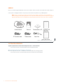
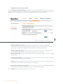
1
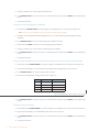
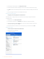
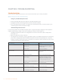
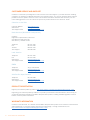
MAX™ IP Response Point™
Administrator’s Guide
TECHNICAL SUPPORT
Telephone Fax
Email
Web
1.800.283.5936
1.801.974.3760
1.801.977.0087
[email protected]
www.clearone.com
document title
CLEARONE PART NOs. 800-158-380-00 (REVISION 1.0 October 2008) © 2008 ClearOne.
All rights reserved. No part of this document may be reproduced in
any form or by any means without written permission from ClearOne.
ClearOne reserves specific privileges. Information in this document is
subject to change without notice.
Chapter 1: Product Overview
1
Appendix : B - Tools and Resources24
PRODUCT OVERVIEW
SERVICE AND SUPPORT
Important safety information
Unpack
System Requirements
Microsoft Response Point Software Download
1
1
2
3
3
3
Assessment checklist
Deployment checklist
24
26
Appendix : C - Compliance
28
Chapter 2: Installation
4
Connecting your conference phone
Connecting Additional MAX IP Response Point
Phones
Manually assigning an IP address
Manually provisioning your MAX IP Response
Point phone
4
4
5
5
Chapter 3: Configuration of the MAX
IP Response Point Phone
5
Web Portal Screens
6
Chapter 4: User Options
10
PROGRAMMING OPTIONS
10
To Change Dynamic Host Configuration Protocol
(DHCP)
10
To Change Host IP Address
10
To Change Subnet Mask
10
To Program a Default Gateway IP Address
11
To Program the Automatic Gain Control (AGC)
and Automatic Level Control (ALC) Settings
11
To Restore Factory Defaults
11
Chapter 5: Response Point Configuration
12
MAX IP Response Point software
To Connect a New Phone or Device:
Installing Response Point Administrator
Response Point Administrator
Adding a New Phone
12
12
12
13
13
Chapter 6: Troubleshooting
16
Troubleshooting MAX IP Response Point Troubleshooting
Response Point Troubleshooting
Customer Service and Support
ClearOne on the Web
North America (Worldwide Headquarters)
Latin America
EMEA
Asia-Pacific/Japan/Oceania
Product registration
WARRANTY INFORMATION
16
16
17
21
21
21
21
21
21
21
21
Appendix : A - Specifications
23
Chapter 1: Product Overview
PRODUCT OVERVIEW
Thank you for purchasing the ClearOne MAX™ IP Response Point™ expandable conferencing phone. MAX IP
Response Point provides premium, full-duplex audio to small conference rooms as a single unit and to larger rooms
as an expanded system. Up to four MAX IP Response Point units can be linked, expanding not only microphone
coverage but loudspeaker coverage and control access as well. This creates even distribution of sound for a more
natural communications experience. Setting up the MAX IP Response Point conferencing phone requires only three
connections: power, network, and the base unit to the conferencing phone. And, the familiar keypad design ensures
that you will be comfortable using the phone, reducing the need for training, and support.
• EXPANDABLE. MAX IP Response Point is ideal for conference rooms and provides complete microphone
and loudspeaker coverage and easy access to controls.
• SUPERIOR AUDIO. The clear, full sound of the MAX IP Response Point facilitates more natural interaction
among participants.
• ONE-TOUCH CONFERENCING. Single-button access to the Response Point voice-activate phone system.
• EASY TO USE. The intuitive, user-friendly controls are simple to operate.
SERVICE AND SUPPORT
If you need additional information on how to set up or operate your MAX IP Response Point conferencing phone,
please contact us. We welcome and encourage your comments so we can continue to improve our products and
better meet your needs.
TECHNICAL SUPPORT
Telephone: 1.800.283.5936(USA) or 1.801.974.3760
Fax: 1.801.977.0087
E-mail: [email protected]
Web site: www.clearone.com
SALES AND CUSTOMER SERVICE
Telephone: 1.800.945.7730 (USA) or 1.801.975.7200
Fax: 1.800.933.5107 (USA) or 1.801.977.0087
E-mail: [email protected]
PRODUCT RETURNS
All product returns require a return authorization (RA) number. Please contact ClearOne Technical Support before
attempting to return your product. Please be sure to return all the items that shipped with your product.
1
Technical Services: 800-283-5936
Important safety information
Read all safety information before using this product.
• Read and understand all instructions.
• Follow all warnings and instructions marked on the product.
• Unplug this product from the wall outlet before cleaning. Use a damp cloth for cleaning. Do not use liquid
cleaners or aerosol cleaners.
• Do not use this product near water, including bathtubs, sinks, or near a swimming pool.
• Do not place this product on an unstable cart, stand, or table.
• Slots and openings in the back, bottom, and/or sides of the product are provided for ventilation. To prevent
overheating, these openings must not be blocked or covered.
• This product should never be placed near or over a radiator or heat register. This product should not be used
in built-in installations unless proper ventilation is provided.
• This product should be operated only from the type of power source indicated on the marking label. If you
are not sure of the type of power supply in your location, consult your dealer or local power company.
• Do not overload wall outlets and extension cords as this can result in the risk of fire or electric shock.
• Never push objects of any kind into this product through cabinet slots as they may touch dangerous voltage
points or short out parts that could result in fire or electric shock.
• Never spill liquids on the product.
• To reduce the risk of electric shock, do not disassemble this product. Opening or removing covers may
expose you to dangerous voltages or other risks. Incorrect reassembly can cause electric shock during
subsequent use.
• Unplug this product from the wall outlet and refer servicing to qualified service personnel under the following
conditions:
»» When the power supply cord or plug is damaged or frayed.
»» If liquid has been spilled into the product.
»» If the product does not operate normally according to the operating instructions.
»» If the product has been dropped or damaged.
»» If the product exhibits a distinct change in performance.
• Do not use this product during an electrical storm. There is a remote risk of electric shock from lightning.
• Do not use this product near intensive care medical equipment or by persons with pacemakers.
• This product can interfere with electrical equipment such as tape recorders, TV sets, radios, computers and
microwave ovens if placed in close proximity.
Save These Instructions
2
Technical Services: 800-283-5936
Unpack
Place the conferencing pod and base unit on a level surface. Ensure you have received all items shown in figure 1.
Use the pack-out diagrams below to verify that you received all components for your MAX product.
Note: Inspect your shipment carefully for obvious signs of damage. ClearOne is not responsible for
product damage incurred during shipment. You must make claims directly with the carrier. If the shipment
appears damaged, retain the original boxes and packing material and contact your carrier immediately.
Figure 1.1 MAX IP Response Point parts
System Requirements
System requirements for Microsoft® Response Point™ can be found at:
• http://www.microsoft.com/responsepoint/resources-datasheet.aspx
Microsoft Response Point Software Download
Microsoft Response Point SP1 is available as a free download at the following location:
• http://www.microsoft.com/responsepoint/features-software-SP1-download.aspx
3
Technical Services: 800-283-5936
Chapter 2: Installation
Connecting your conference phone
Connect the Connection cable from the Link Out jack on the base unit to the Link In jack on the conferencing pod
(see figure 2.1).
Figure 2.1 Connecting the MAX IP Response Point
Warning: DO NOT plug a laptop or PC into the Link Out jack on the base unit or conferencing pod as
severe electrical damage could occur.
Connect the base unit to the Ethernet jack using the Ethernet cable.
Connect the power cord to the base unit and plug it directly into an electrical outlet.
Connecting Additional MAX IP Response Point Phones
Connect the 12’ Connection cable to the Link Out jack on the first phone and to the Link In jack on the second
phone (see figure 2.2).
From Link Out
25' Connection cable
To Link In
12' Connection cable
To Link In
To Link Out on Base Unit
Figure 2.2 Connecting additional units
Continue linking additional MAX IP Response Point phones in the same fashion. A total of four units may be
connected.
4
Technical Services: 800-283-5936
Chapter 3: Configuration of the MAX IP Response
Point Phone
Manually assigning an IP address
If DHCP is disabled or you wish to assign a static IP address, perform the following steps:
1. Press and hold the REDIAL/PROG key until the program icon appears on the LCD screen.
Note: If a key is not pressed within 30 seconds of entering program mode, the MAX IP Response
Point phone will beep and return to normal operation mode.
2. Press the 2 key. The default IP address is displayed on the LCD screen. If this address was obtained from
DHCP, then you can use it to access the web interface. If you cannot access the web interface using this
address, then you need to either configure DHCP as explained above so that the IP address can be obtained
automatically, or you must manually enter a static IP address. Continue with step 3 to manually enter a static
IP address for the MAX IP Response Point phone.
3. Press the 1 key. The current DHCP setting is displayed on the LCD screen. A “1” indicates that DHCP
mode is enabled; a “0” indicates that DHCP mode is disabled.
4. If “0” is the current setting, then continue with step 8, otherwise continue with step 5.
5. Press the REDIAL/PROG key. The current DHCP mode “1” will flash on the LCD screen.
6. Press the 0 key. The new DHCP mode “0” will flash on the LCD screen.
7. Press the REDIAL/PROG key. DHCP mode is disabled.
8. Press the 2 key. The current IP address (such as 0.0.0.0) will be displayed on the LCD screen.
9. Press the REDIAL/PROG key. The current IP address will flash on the LCD screen.
10.Press the CLEAR key. The current IP address will be deleted one character at a time.
11.Using the number keys, enter the static IP address. Use the * key to enter the decimal separators in the
IP address.
12.Press the REDIAL/PROG key. The new static IP address is activated in the MAX IP Response Point phone.
13.Press the 3 key and repeat steps 9-12 above to set the subnet mask, then continue with step 14.
14.Press the REDIAL/PROG key. The MAX IP Response Point phone will reboot.
Manually provisioning your MAX IP Response Point phone
The easiest way to manually provision your MAX IP Response Point phone is through the web interface. To access
the web interface, perform the following steps:
1. Press and hold the REDIAL/PROG key until the program icon appears on the LCD screen.
2. Press the 2 key. The phone’s IP address will be displayed on the LCD screen.
5
Technical Services: 800-283-5936
3. Make note of the IP address and press the CLEAR key. The phone will exit Program mode.
4. Start Internet Explorer.
Note: Only Internet Explorer, release 6.0 or later with Java 1.5 or later installed, is supported by the MAX IP
Response Point phone.
5. Enter the phone’s IP address into the Internet Explorer address field and press the ENTER key on your
computer’s keyboard. (You can also enter the DNS name or the phone’s name on the network in order to get
to the web interface login screen.)
6. The MAX IP Response Point’s web portal will appear, displaying the Device Information screen.
Web Portal Screens
The following sections display each of the screens included in the MAX IP Response Point web portal and describe
all of the settings that can be modified through each of the screens.
Device Information screen
The Device Information screen (see figure 3.2) displays all of the system information for your MAX IP Response
Point phone. The information fields are self-explanatory. Please note that the last four digits of the MAC address
are used as an identifier in the system name. By default, the system name is in the format of MAX1AV- followed by
the last four digits of the MAC address. The MAC address is a unique address in hexadecial format that can also
be found on the label attached to the back of your MAX IP Response Point base unit. This screen (and all other
screens) also includes a link to the Registration page in order to register your MAX IP Response Point phone with
ClearOne. Simply click the Registration link to go there.
Figure 3.2 Device Information screen
6
Technical Services: 800-283-5936
Configuration: User Preferences screen
Use the Configuration: User Preferences (see figure 3.3) screen to enable/disable automatic level control (ALC)
and automatic gain control (AGC), to mute/unmute the incoming ringer, to select the incoming ringer melody, to set
the time zone, and to determine if you want the time automatically adjusted for Daylight Savings.
Figure 3.3 Configuration: User Preferences screen
• Enable automatic level control: Click this check box to enable ALC or uncheck it to disable ALC.
ALC (automatic level control) automatically adjusts microphone levels to ensure participants’ voices are
transmitted at consistent levels regardless of whether people are speaking loudly or softly.
• Enable automatic gain control: Click this check box to enable AGC or uncheck it to disable AGC. AGC
(automatic gain control) adjusts (softer and louder) input audio to a consistent level.
• Mute incoming ringer: Click this check box to mute the incoming ringer (or uncheck it to allow the ringer to
ring normally).
• Incoming ringer melody: Click the drop-down box to select from the five available melodies. Click the Play
button to listen the selected melody on the phone.
• Time zone: Click the drop-down box to select from the available time zones. Choose the appropriate time
zone for your location. The time zone is necessary for error logging.
• Auto adjust for Daylight Saving Changes: Click this check box to have the time automatically adjusted for
Daylight Savings or uncheck it if Daylight Savings time is not observed in your area.
Click the Apply button to activate any changes made to this screen.
7
Technical Services: 800-283-5936
Configuration: Trace/Logging Settings screen
Use the Configuration: Trace/Logging Settings screen (see figure 3.4) to control logging for general audio
processing and SIP subsystems, as well as system logs and trace flags.
Figure 3.4 Configuration: Trace/Logging Settings screen
Note: This screen is only used to diagnose problems you might be experiencing on your MAX IP
Response Point phone. Before enabling any of these logs, please call our customer service department to
receive instructions on which logs to enable.
• Enable system log: Click this check box to have the system log displayed on the Device Log File screen.
• Active trace flags: Click the Apply button to activate trace flags.
• General Logging: These are various audio and call control subsystems for which logs can be generated if
enabled.
• SIP Message Logging: Allows capture of all inbound and outbound SIP messages for signalling
diagnostics.
• Turn Off Logs: Click this button to turn off logging.
Click the Apply button to cause logs selected in General Logging and SIP Logging sections to be displayed on the
Device Log File screen.
View Log: Device Log File screen
Use the View Log: Device Log File screen (see figure 3.5) to keep record of device log data. You can then
download the log for review by clicking the Download button. The log shows the last 8 KB of log data. Click the
Update button to get the most recent 8 KB of data. Click the Clear button to clear the log.
Note: This screen is only used to diagnose problems you might be experiencing on your MAX IP
Response Point phone. Please call our customer service department to receive instructions on how to
interpret the logs shown here.
8
Technical Services: 800-283-5936
Tools: Diagnostics - VoIP Statistics screen
Use the Tools: Diagnostics - VoIP Statistics screen (see figure 3.6) to check the phone state, update firmware,
reboot the phone, and restore default settings.
Figure 3.5 View Log: Device Log File screen
• Check Phone State: Click this button to view VoIP statistics, including the number of packets received, the
number of packets lost, and the percent packet loss. These statistics are displayed in real time and are only
available when the phone is in a call. At such time, a green check mark appears in the check box above the
Check Phone State button.
• Update Firmware: You will receive the firmware update file (ggsip_all, for example) and, using the web
interface only, you will enter that name directly or browse to its location on your computer by using the
Browse button, then clicking the Update button. The MAX IP Response Point phone’s firmware is updated.
• Reboot Device: Click this button to reboot your MAX IP Response Point phone.
• Restore Default Settings: Click this button to restore the default settings of your MAX IP Response
Point phone.
Figure 3.6 View Log: Device Log File screen
9
Technical Services: 800-283-5936
Chapter 4: User Options
PROGRAMMING OPTIONS
To allow for individual preferences and enhance ease of use, the following features can be programmed:
DHCP, host IP, subnet mask, default gateway IP address, ringer melody, VLAN on/off, help line number, and
AGC/ALC. You can also restore factory defaults.
To Change Dynamic Host Configuration Protocol (DHCP)
1. Press and hold the REDIAL/PROG key until the Program icon appears on the LCD screen (see figure 4.1)
Figure 4.1 MAX IP Response Point LCD Program icon
2. Press 1 to enter the DHCP menu. There are two options: 1 - enable DHCP; and 0 - disable DHCP.
3. Press REDIAL/PROG. The current DHCP setting will flash.
4. Press keys 1 or 0 to enable or disable DHCP.
5. Press REDIAL/PROG to save the selection; a confirmation tone will play. Press CLEAR to exit programming.
6. The phone will reboot.
To Change Host IP Address
Press and hold the REDIAL/PROG key until the Program icon appears on the LCD screen (see figure 4.1).
Note: DHCP must be disabled in order to change the host IP address manually.
1. Press 2 to enter the Host IP Address menu. The current host IP address will be displayed.
2. Press REDIAL/PROG. The current host IP address will flash.
3. Press and hold CLEAR to erase the current host IP address.
4. Using the number keys, enter the desired host IP address.
5. Press REDIAL/PROG to save the selection; a confirmation tone will play. Press CLEAR to exit programming
mode.
6. The phone will reboot.
To Change Subnet Mask
1. Press and hold the REDIAL/PROG key until the Program icon appears on the LCD screen (see figure 4.1).
Note: DHCP must be disabled in order to change the subnet mask manually.
2. Press 3 to enter the Change Subnet Mask menu. The current subnet mask will be displayed
3. Press REDIAL/PROG. The current subnet mask will flash.
4. Press and hold CLEAR to erase the current subnet mask.
10
Technical Services: 800-283-5936
5. Using the number keys, enter the desired subnet mask.
6. Press REDIAL/PROG to save the selection; a confirmation tone will play. Press CLEAR to exit programming
mode.
7. The phone will reboot.
To Program a Default Gateway IP Address
1. Press and hold REDIAL/PROG until the Program icon will appear on the LCD screen (see figure 4.1).
Note: DHCP must be disabled in order to change the subnet mask manually.
2. Press 4 to enter the Default Gateway IP Address menu. The current default gateway IP address will be
displayed.
3. Press REDIAL/PROG. The current default gateway IP address will flash.
4. Press and hold CLEAR to erase the current default gateway IP address.
5. Using the number keys, enter the desired default gateway IP address.
6. Press REDIAL/PROG to save the selection; a confirmation tone will play. Press CLEAR to exit programming
mode.
7. The phone will reboot.
To Program the Automatic Gain Control (AGC) and Automatic Level Control (ALC) Settings
1. Press and hold the REDIAL/PROG key until the Program icon appears on the LCD screen (see figure 4.1).
2. Press and hold the 8 key. The current AGC setting number will be displayed on the LCD screen.
3. Press REDIAL/PROG. The current setting number will flash.
4. Enter a new setting number using the table shown in figure 4.2.
Setting
Speaker AGC
Microphone ALC
1
On
On
2
On
Off
3
Off
On
4
Off
Off
Figure 4.2 MAX IP Response Point gain control table
5. Press REDIAL/PROG to save the selection; a confirmation tone will play. Press CLEAR to exit programming
mode.
To Restore Factory Defaults
1. Press and hold the REDIAL/PROG key until the Program icon will appear on the LCD screen (see figure 4.1).
2. Press and hold the 9 key. The number 8 will repeat across the LCD screen.
3. Press REDIAL/PROG to save the selection; a confirmation tone will play. Press CLEAR to exit programming
mode.
4. The phone will reboot.
11
Technical Services: 800-283-5936
Chapter 5: Response Point Configuration
MAX IP Response Point software
This section describes how to integrate the MAX IP Response Point into your existing Response Point system.
Microsoft Response Point phones and devices have a blue button that allows you to use Response Point features,
such as transferring a call using voice activated dialing.
To Connect a New Phone or Device:
1. Using an Ethernet cable, connect the phone to the LAN.
2. Connect the phone to a power source with the power cord.
3. Next, install the Administrator program.
Installing Response Point Administrator
Administrator is the program you’ll use to administer and monitor Microsoft® Response Point™. With it, you can
configure phones, users, and extension numbers, and set other options. You should install Administrator on the
computer of the person who will manage the Response Point system.
To install Administrator:
1. Insert the Response Point CD.
2. Select Install Microsoft Response Point Administrator, and click Next.
3. On each page, click Next when you are ready to move to the following page of the wizard.
4. When you reach the last page of the wizard, click Finish.
Starting Response Point Administrator and Logging On to the Base Unit
To start Administrator and log on to the base unit:
1. Click Start, point to All Programs, and click Microsoft Response Point Administrator.
2. Select the base unit that you just installed, and click Connect.
Note: A few seconds may elapse. If you don’t see the base unit listed, it’s likely that the base unit or the
computer on which Administrator is running is not connected properly to the LAN. Make sure all cables
and power cords are connected.
3. When prompted to provide a password, type the default password: admin (case sensitive).
»» It is recommended that you change this password as soon as possible for security purposes.
4. Click Connect again.
Note: Before you configure your device, it is important that you set the date and time on the base unit. If
you do not take this step first, you may have to reconfigure any phones you have already configured.
To set the date and time on the base unit:
1. In Administrator, click the Base Unit button.
12
Technical Services: 800-283-5936
2. In the Tasks pane, under Properties, click Change Date and Time.
3. In the Set Date and Time on Base Unit dialog box, enter the correct values for the date and time settings.
4. Click OK. The base unit will automatically restart. After it restarts, the base unit will display the new date and
time.
5. Next, you’ll configure the new device in your Response Point system.
Response Point Administrator
Configuring a Phone Using Response Point Administrator
The following step is to configure the device you connected to the LAN, using the Configure Phone Wizard.
To configure a phone:
1. In Administrator, click the Phone System button.
2. In the Tasks pane, under Phone, click Add Phone, which displays the Configure Phone Wizard.
3. Confirm that the phone is connected and plugged in, select the check box at the bottom of the Have you
connected your phone page, and click Next.
4. In the Phones found on the network list, click one of the phones you just connected, and click Next.
Adding a New Phone
To add a new phone in Response Point Administrator
1. Launch Response Point Administrator.
• Connect to the server.
13
Technical Services: 800-283-5936
• Click Add Phone.
A. Ensure the MAX IP Response Point is powered and connected to the network.
B. The MAX IP Response Point will appear in the device list.
C. Highlight the device, click Next.
D. Select Assign User to Assign or Create a user and click Next.
• From the list, choose the user you wish to assign to the phone, highlight and click OK.
• To Create a New User: select New User.
• Follow the New User wizard.
E. Assign your user to “Recieve calls on this phone”. Click Next.
14
Technical Services: 800-283-5936
F. Name the phone, click Next.
G. Click Finish to complete the process.
The MAX IP Response Point is now ready for use with your Response Point phone system.
15
Technical Services: 800-283-5936
Chapter 6: Troubleshooting
Troubleshooting
Use this section to diagnose and resolve the most common issues that may occur with your product.
MAX IP Response Point Troubleshooting
Caring for your MAX IP Response Point
• Follow all warnings and instructions marked on your MAX IP Response Point.
• Unplug base unit and conferencing pod from the wall outlet before cleaning.
• Do not use liquid or aerosol cleaners. Use a damp cloth moistened with water to clean the outside of your
conferencing pod or base unit and power supply.
Troubleshooting Common Issues
If you are having trouble with your MAX IP Response Point, it might be improperly configured or other equipment
might be malfunctioning. To begin, check for the following (or consult the chart in figure 6.1):
• The MAX IP Response Point base unit is plugged into an electrical outlet with the proper voltage and its
power light is on.
• Make sure cables are securely connected.
• The equipment the other party is using is comparable in quality to your MAX IP Response Point conferencing
phone and is working properly. While the MAX IP Response Point works with speakerphones, cell phones,
handsets or installed conferencing systems, the quality of the conference will be impacted if the party you are
conferencing with has poor quality equipment.
If you hear/see:
Possible issue:
Try this:
No dial tone.
Base unit is not connected to an
Ethernet jack.
Connect the base unit to the
Ethernet jack using the supplied
Ethernet cable.
DHCP failure.
Check for IP address.
The other party’s room is too noisy.
Ask the other party to turn off noisy
equipment.
Packet loss or delay.
Contact Network Administrator.
The equipment on the far end is of
inferior quality.
The equipment should be
upgraded. Participants can try
sitting closer to equipment and
eliminating background noise.
A G.729.1 codec is selected as the
priority codec.
Move the G.711 or G.729 codecs up
in the priority order.
Local AGC is turned off.
Activate local AGC.
Far end AGC is turned off.
Activate far end ALC.
Local ALC is turned off.
Activate local ALC.
Far end AGC is turned off.
Activate far end AGC.
Static or noise.
Poor audio quality.
Far end is difficult to hear.
Far end is having difficulty hearing
you.
16
Technical Services: 800-283-5936
Response Point Troubleshooting
Six Questions to Ask Before Troubleshooting the System
Before taking any drastic measures to repair the Response Point phone system, ask yourself the following
questions:
1. Did you verify the IP address? Response Point identifies a device by the IP address that is assigned to it. It’s
important to locate this information when troubleshooting because it can provide valuable information.
2. In what order did you set up the hardware? If you plug in the phones before the base unit, the phones may not
appear in the list of discovered devices on the Phone System page in the Response Point Administrator. Be sure
to first plug in the base unit, then the analog telephone adapter (ATA) if applicable, and then the phones into their
respective power sources.
3. Have you eliminated potential issues? By ruling out the improbable, you can become closer to identifying the
actual problem. For example, if you can’t detect a dial tone on a phone, disconnect that phone from Response
Point, and plug an analog phone directly into the Public Switched Telephone Network (PSTN) line. Use your mobile
phone to call the analog phone. If the analog phone doesn’t receive the incoming call, then you know that the phone
line is faulty, not the Response Point system, and you’ll need to call your phone service provider for assistance.
4. Are the cables in the proper ports? Make sure that all of the Ethernet cables, the phone line cables, and power
cords are connected to the correct ports and electrical outlets. For example, if a phone does not appear in the list
of discovered devices on the Phone System page in the Response Point Administrator, its Ethernet cable may be
connected to the phone port labeled “PC” instead of to the port labeled “LAN.”
5. Is the Response Point Administrator panel well organized? In the Response Point Administrator, the Phone
System page displays a list of all configured Response Point users, phones, and phone lines. This list does not
automatically refresh after you remove a user or a device. For example, the list may show that there are phones
still using an IP address that the base unit no longer acknowledges. It’s good practice to manually delete outdated
users and phones, so you don’t include irrelevant devices and information while problem-solving in the future.
6. Are you troubleshooting the correct base unit? Depending on the configuration, you might be managing multiple
base units for one organization. Response Point automatically assigns a name to the base unit; this name cannot
be customized or changed manually. Carefully record each base unit name so there’s no confusion when it’s time to
troubleshoot.
17
Technical Services: 800-283-5936
Issue 1: Undetected Devices
Problem: “The device that I configured has a red X next to its name in the discovered-devices list.”
Cause: IP addresses are leased to each device for an allotted period of time. Using Dynamic Host Configuration
Protocol (DHCP) service enables the phone system to automatically reconnect when IP addresses change.
Occasionally, a device might lose its IP address because this connection process is interrupted or delayed.
Solution: Reconfigure the device using the configuration wizards in the Response Point Administrator. Or, turn the
device off and on first, and then reconfigure it.
Problem: “The base unit only discovered two of the three phones that I just connected. The first phone that I
plugged in doesn’t appear in the discovered-devices list.”
Cause: The DHCP server issues IP addresses to all Response Point hardware so that the base unit can detect the
presence of the devices and communicate data to them using standard protocols . When you plug in a phone, it
sends a message to the base unit, signaling its presence. However, if you plug in three phones, for example, and
then turn on the base unit, the first phone will send its alert before the base unit can process the message.
Solution: Wait several minutes for the phone to signal its presence to the base unit again, and then reconfigure the
phone. Or, turn on the base unit first and allow it to fully register before plugging in any phones.
Problem: “The phone that appeared in the discovered-devices list before isn’t there now.”
Cause: If you restored a backup from a previous system configuration, the phones that you set up after the
specified configuration will be automatically removed from the discovered-devices list.
Solution: Reconfigure the phone using the configuration wizards in the Response Point Administrator, or turn the
server off and then on .
Issue 2: Unrecognized IP Addresses
Problem: “The IP address on the phone’s display is different than the IP address that appears in the
discovered-devices list.”
Cause: Response Point comes with a built-in DHCP service, which is responsible for issuing IP addresses to
devices connected to the LAN. If you’ve configured a wireless router on the network, it comes equipped with an
additional DHCP service. This configuration will then have two competing DHCP servers issuing IP addresses
on different subnets. Therefore, the auxiliary DHCP server that is associated with the wireless router issued the
IP address that you see on the phone’s display; the DHCP server that is native to Response Point issued the IP
address that you see on the discovered-devices list.
Solution: Convert the wireless router into a “wireless access point” by disabling its DHCP service. Or, be sure to
purchase a wireless access point without DHCP functionality before installing Response Point.
Issue 3: Faulty Connection to Phone
Problem: “There’s no dial tone.”
Cause: For unknown reasons, phones connected to a LAN might “freeze” occasionally.
Solution: Turn the phone off and then on again. It may be necessary to reconfigure it using the configuration
wizards in the Response Point Administrator.
Problem: “The park and retrieve features don’t work on certain phones.”
Cause: Overall, the park and retrieve commands should work properly system-wide, but for undetermined reasons,
individual phones might occasionally encounter problems when users try to park and retrieve calls.
Solution: Perform a factory reset on the faulty phone. To do this, obtain the IP address of the phone. Open a
browser window, and type in the address bar: “Error! Hyperlink reference not valid.” Click the Reboot tab in the
18
Technical Services: 800-283-5936
upper-right corner of the page . Then select Factory Restore, and click the Restore button.
Issue 4: Faulty Connection to Phone Lines
Problem: “There’s no dial tone.”
Cause: If you’ve eliminated the possibility that your phone service is down, the phone line might have lost
connection to the base unit. The LEDs on the base unit should remain constantly lit when the associated phone line
is properly configured. When the connection is faulty, the corresponding LED may flutter or sporadically flash on and
off. For additional information regarding phone line-related malfunctions, see “Issue 7: Dropped Calls.”
Solution: Reconfigure the phone line using the configuration wizards in the Response Point Administrator.
Problem: “The Automated Receptionist is not answering calls, and callers hear incessant ringing.”
Cause: A single RJ11 line might be connected to the base unit, but you ordered two lines from your phone service
provider. Standard RJ11 lines are designed to handle up to two phone lines on a single plug; however, the phone
line adapter treats a single plug as a single line .
Solution: Install a splitter to separate the shared pins on the RJ11 plug.
Issue 5: Faulty Connection to Simple Mail Transfer
Protocol (SMTP) Server
Problem: “The voicemail-to-e-mail feature isn’t working properly. Users who have enabled this setting haven’t
received any voice messages as e-mail attachments yet.”
Cause: The SMTP server settings are probably incorrect, if you’ve taken the following actions:
• In the Response Point Administrator, selected the Allow sending voicemail in e-mail check box in the
Configure E-mail Server dialog box—a required step before the individual setting that users configure can
work.
• Confirmed that all of the required fields in the Configure E-mail Server dialog box have the correct
information.
• In the Response Point Assistant, verified that users have selected the Enable voicemail check box on the
Voicemail tab.
Solution 1: Visit the Web site of your Internet service provider, and locate the correct SMTP server settings. Taking
this route, however, might force you to wade through unnecessary information before finding what you need. Try
this shortcut instead: When you type “POP3 settings, <name of ISP>” in the search box of a Web browser, a list
of search results containing the correct information will be available. Note the outgoing-SMTP-server address and
the port number; then in the Response Point Administrator, enter this information in the corresponding fields before
checking the connection by sending a test e-mail.
Solution 2: If you’ve deployed Response Point with Windows® Small Business Server, try adjusting the following
e-mail server settings in the Configure E-mail Server dialog box in the following order: 1) Click the Connect to the
server anonymously option instead of specifying a user . 2) Under User Information, type “PhoneSystem@<insert
your business e-mail alias>.com.” 3) Clear the This server requires SSL encryption check box.
Issue 6: Logon Attempts Failed
Problem: “After verifying that logon information is correct, users still can’t log in to Response Point Assistant.”
Cause: It might be that the computers running the Response Point Assistant are set up to use Internet Protocol
security (IPsec), which is an unsupported environment for this application.
Solution: Make sure that the computers running the Response Point Assistant are not configured for IPsec.
Issue 7: Dropped Calls
Problem: “External callers are experiencing dropped calls.”
19
Technical Services: 800-283-5936
Cause: If you’ve verified that the hardware, Public Switched Telephone Network (PSTN) lines, and service
connections are working, dropped calls might be caused by a faulty phone line in your rollover sequence. In these
cases, the base unit does not actually drop the call, but rather the call terminates automatically when passed to the
malfunctioning phone line.
Solution: Ask your phone service provider to fix the faulty line or to position it at the end of your rollover pattern.
Incoming calls will be less likely to reach the last phone line in the sequence.
Issue 8: Low Call Volume
Problem: “External callers are having difficulty hearing internal callers.”
Cause: The analog telephony adapter (ATA) needs to be adjusted.
Solution: In the Response Point Administrator, click the D-Link or Quanta button, and navigate to the Web page
that offers supports for the ATA. From this page, you can adjust the appropriate settings of the adapter until the call
volume is audible to external callers.
Issue 9: Speech Misrecognition
Problem: “The speech recognition system scrambles hard-to-pronounce user names.”
Cause: The text-to-speech (TTS) engine converts the text stored in the Response Point Administrator into artificial
speech.
Solution: Because the speech recognition system supplies the auto attendant with the TTS pronunciations of the
names that you enter in the User Properties dialog box, ask users to carefully articulate the correct pronunciation of
their names when using the Record Audio Using a Phone dialog box, or to type a phonetic spelling of their names
in the Nickname box. For example, for the user “Rebecca Laszlo”, type “Rebecca Lazlow” in this field. The system
will then use the actual recording of the name in the user’s own voice or will pronounce the name according to the
phonetically spelled entry.
Issue 10: Unlit Message Waiting Indicator (MWI)
Problem: “The MWI on the phone doesn’t light up when callers leave voice messages for the specified user.”
Cause: The MWI only illuminates when callers leave voice messages for the primary user assigned to a phone.
Solution: Users that you assign to a particular phone are listed on the Who will receive calls on this phone page in
the Configure Phone Wizard. Response Point recognizes the first user in the list as the primary user of that phone.
To ensure that the MWI lights up when voice messages arrive for a specified user, move that user to the top of the
list with the Move User Up button, making him the primary user.
20
Technical Services: 800-283-5936
Customer Service and Support
ClearOne is committed to providing best-in-class customer service and support. If you need assistance installing,
configuring, or operating your MAX IP Response Point conference phone, or if you have questions about ClearOne
products or services, please contact us at one of the locations listed below. ClearOne also welcomes your comments and suggestions so we can continue to improve our products and serve our customers’ needs.
ClearOne on the Web
Corporate Website:
Sales Email:
Tech Support Email:
www.clearone.com
[email protected]
[email protected]
North America (Worldwide Headquarters)
ClearOne
Edgewater Corporate Park, South Tower
5225 Wiley Post Way, Suite 500
Salt Lake City, Utah 84116 USA
Telephone:
Fax: Toll-Free:
Tech Support:
801-975-7200
801-977-0087
800-945-7730
800-283-5936
Latin America
Telephone:
Fax: Sales Email:
Tech Support Email:
801-975-7200
801-977-0087
[email protected]
[email protected]
EMEA
Telephone:
Sales Email:
Tech Support Email:
44 (0) 1189 036 053
[email protected]
[email protected]
Asia-Pacific/Japan/Oceania
Telephone:
Sales Email:
Tech Support Email:
801-303-3388
[email protected]
[email protected]
Product registration
Register your ClearOne product(s) online at http://www.clearone.com/support/registration.php?content=main.
Registering your ClearOne product(s) enables us to provide you with better technical assistance, and to notify you
of important information regarding your MAX IP Response Point product, including available upgrades, technical
bulletins, and new product information.
WARRANTY INFORMATION
ClearOne Communications, Inc. warrants that this MAX IP Response Point product is free of defects in both material
and workmanship. For complete warranty information including length, coverage, and limitations, visit
http://www.clearone.com/support/warranty.php?content=main
21
Technical Services: 800-283-5936
Appendix : A - Specifications
DIMENSIONS (W x D x H)
Phone section: 10.5” x 10.5” x 3”
(26.7 cm x 26.7 cm x 7.6 cm)
Base unit: 4.25” x 5.5” x 2.5”
(10.8 cm x 14 cm x 6.4 cm)
WEIGHT
Phone section: 2.7 lb (1.2 kg)
Base unit: .6 lb (0.27 kg)
Shipping: 10 lb (4.5 kg)
ENVIRONMENTAL
Operating Temperature: 32–122° F (0–50° C)
Storage temperature: 41–158° F
(5–70° C)
Operating Humidity: 15 to 80%
Storage humidity: 10 to 90%
POWER
Base unit:
Auto-adjusting power module;
100–240VAC; 50/60 Hz
NETWORK
10/100 Ethernet
RJ-45
KEYPAD
Alphanumeric standard keypad
LOUDSPEAKER
Volume: 90 dBspl A weighted @ 1 ft
Bandwidth: 200Hz - 3.3kHz
RECORD OUTPUT
Connector: 2.5 mm mono audio jack
Impedance: <1000 ohm
Bandwidth: 200Hz–3.3kHz
Dynamic Range: 60dB
THD <.01%
ECHO CANCELLATION
Tail Time: 128 mS x 3
NOISE CANCELLATION
Dynamic noise cancellation
CERTIFICATIONS
FCC Part 15 Class A
FCC Part 68
UL Certified
MODELS
MAX IP Response Point*
MAX IP Response Point Expansion Kit*
*Call your sales representative for part numbers
23
Technical Services: 800-283-5936 - BETA
Appendix : B - Tools and Resources
Assessment checklist
The Assessment Checklist is provided to help you with Response Point planning.
Assessment Task
Business Sizing
Number of phone users
Number of additional user phones
Number of non-user phones
Number of sites
Site connectivity details
Phone usage
Telephone Usage
Average inbound calls per day
Average inbound call type
Average outbound calls per day
Average long-distance usage
Anticipated voicemail usage
Additional Considerations
Additional hardware requirements
Dedicated line requirements
Feature requirements
Administrative roles
Physical Network
24
Technical Services: 800-283-5936 - BETA
Results
a
Router details
Switch types
Switch connectivity
Open switch ports
Logical Network
Subnets
DHCP Types
SMTP server information
Data Security
Firewall type
Firewall VoIP support
Infrastructure
Ethernet traffic testing
Network cable testing
Patch cable type
Sufficient network jacks
Sufficient power outlets
Active network drops
Data Center power capacity
Data Center UPS capacity
Provider Information
PSTN or VoIP
Number of PSTN lines
25
Technical Services: 800-283-5936 - BETA
PSTN features
PSTN provider details
VoIP provider details
Internet/WAN connectivity
Deployment checklist
Use this Checklist to prepare for a Response Point deployment. It will ensure that all necessary planning tasks are
preformed and all necessary information has been recorded.
Planning Task
DHCP Server
Using single DHCP server
DHCP server compatibility
DHCP lease time sufficient
DHCP static reservations set
Single subnet for phone system
Switch and Router Requirements
Ethernet patch cables connected
VoIP QoS Configured on router.
Switch ports set to full duplex
Switch ports assigned and active
Integration Requirements
SMTP server type
SMTP server IP address
SMTP server FQDN
26
Technical Services: 800-283-5936 - BETA
Results
a
SMTP server port
Provider Information
Lines provisioned for Response Point
Dedicated lines provisioned
Features enabled on all lines
VoIP telephony bandwidth sufficient
VoIP IAD sufficient
Firewall and router support VoIP
Infrastructure
Data center power capacity
Data center UPS capacity
Administration
Administrators identified
Administration password defined
Response Point base unit IP address
Response Point Administrator software
installed
Administrator training
27
Technical Services: 800-283-5936 - BETA
Appendix : C - Compliance
EUROPEAN COMPLIANCE
Conformity of the equipment with the guidelines below is attested by the CE mark.
EC Declaration of Conformity
Manufacturer’s Name: ClearOne Communications
Manufacturer’s Address: Edgewater Corporate Park South Tower
5225 Wiley Post Way, Suite 500
Salt Lake City, Utah 84116 U.S.A.
EU Representative Name: ClearOne Communications Ltd.
EU Representative Address: Atlantic House
Imperial Way
Reading Berkshire
RG2 0TD
United Kingdom
Model: MAX IP Response Point & MAXAttach IP Response Point
Product Standard(s) to which Conformity of the Council Directive(s) is declared:
EMC - 2004/108/EC “Electromagnetic Compatibility (EMC) Directive”:
EN 55022: 2006 (Emissions) Information technology equipment - Radio disturbance characteritics - Limits and methods of measurement.
EN 61000-3-2: 2004 Part 3: Limits - Section 2: Limits for harmonic current emissions.
EN 61000-3-3: 2002 Section 3: Limitation of voltage fluctuations and flicker in low voltage supply systems for equipment with rated current up to and including 16 A.
EN 55024: 1998 (Immunity) + A1+A2 Information technology equipment - Immunity characteristics -Limits and methods of measurements.
EN 61000-4-2: 2001 Electrostatic Discharge Immunity
EN 61000-4-3: 2002
Radiated RF Immunity
EN 61000-4-4: 2004 Electrical Fast Transients Immunity
EN 61000-4-5: 2005 Lightning Surge Immunity
EN 61000-4-6: 2004 Conducted RF Immunity
EN 61000-4-8: 1993 Power Frequency Magnetic Field Immunity
EN 61000-4-11: 2004 Voltage Dips and Voltage Interruptions
Safety - 73/23/EEC “Low Voltage Directive (LVD)”:
28
Technical Services: 800-283-5936 - BETA
IEC 60950-1: 2001 Safety of Information Technology Equipment, Including Electrical Business Equipment.
RoHS - 2002/95/EC Restrication of the Use of certain Hazardous Substances in Electrical and Electronic
Equipment (EEE) & WEEE - 2002/96/EC Waste of Electrical and Electronic Equipment (EEE).
We herein certify that the products listed above are in compliance with the EU directive 2002/95/EC and EU directive
2002/96/EC.
We, the undersigned, hereby declare that the equipment specified above conforms to the above directives and
standards. Date of Issue: ?
Legal Representative in Europe
/s/ Greg A. LeClaire
Signature Greg A. LeClaire CFO
29
Technical Services: 800-283-5936 - BETA