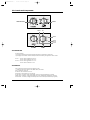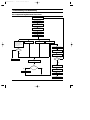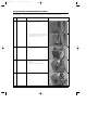
1
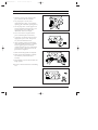
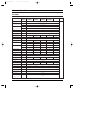
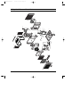
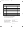
AW05E05A(AW0510)-front
6/9/00 4:54 PM
Page 2
ROOM AIR CONDITIONER
AW05B05A(AW0500, AW0500A)
AW05E05A(AW0510, AW1510A)
AW05F05A
SERVICE
AIR CONDITIONER
Manual
CONTENTS
1. Precautions
2. Product Specifications
3. Installation and Operating
Instructions
4. Disassembly and Reassembly
5. Troubleshooting
6. Exploded Views and Parts List
7. Block Diagram
8. Wiring Diagram
AW05E05A(AW0510)-1
6/9/00 5:10 PM
Page 1-1
1. Precautions
1. Warning: Prior to repair, disconnect the
power cord from the circuit breaker.
2. Use proper parts: Use only exact
replacement parts. (Also, we recommend
replacing parts rather than repairing them.)
3. Use the proper tools: Use the proper tools
and test equipment, and know how to use
equipment may cause problems laterintermittent contact, for example.
Fig. 1-1 Avoid Dangerous Contact
4. Power Cord: Prior to repair, check the
power cord and replace it if necessary.
5. Avoid using an extension cord, and avoid
tapping into a power cord. This practice
may result in malfunction or fire.
6. After completing repairs and reassembly,
check the insulation resistance, Procedure:
Prior to applying power, measure the
resistance between the power cord and the
ground terminal. The resistance must be
greater than 30 megohms.
Fig. 1-2 No Tapping and No Extension Cords
7. Make sure that the grounds are adequate.
8. Make sure that the installation conditions
are satisfactory. Relocate the unit if
necessary.
9. Keep children away from the unit while it is
being repaired.
10. Be sure to clean the unit and its surrounding
area.
Fig. 1-3 No Kids Nearby!
Fig. 1-4 Clean the Unit
Samsung Electronics
1-1
AW05E05A(AW0510)-1
6/9/00 5:10 PM
Page 1-2
MEMO
1-2
Samsung Electronics
AW05E05A(AW0510)-1
6/9/00 5:10 PM
Page 2-1
2. Product Specifications
2-1 Table
Item
Unit of
Measure
AW05B05A
(AW0500)
AW05E05A
(AW0510)
AW05B05A
(AW0500A)
AW05E05A
(AW0510A)
AW05F05A
-
Window
Inches
17 13/16 x 12 3/8 x 13 9/16
mm
452 x 314 x 345
Inches
19 11/32 x 14 7/8 x 17 11/32
Width x Height x Depth
mm
491 x 378 x 440
Voltage:
Volt
115
-
Single
Frequency
Hz
60
Operating Current
A
5.6
4.8
5.6
4.8
4.8
Power Consumption
W
625
515
625
515
560
Type
Dimensions:
Width x Height x Depth
Packing Size:
Phase
R-22
Refrigerant Type
FREON
Refrigerant Charge
OZ(kg)
9.0(255)
12.0(340)
9.0(255)
12.0(340)
12.0(340)
Cooling Capacity
BTU/h
5,000
5,100
5,000
5,100
-
Kcal/h
-
-
-
-
1,250
(BTU/h,W)
8.0
9.7
8.0
9.7
9.7
(Kcal/hw)
-
-
-
-
2.22
Humidity Removed
LT/h
1.5
1.5
1.5
1.5
1.5
Air Circulation
C.F.M
134
125
134
125
125
Net Weight
LBS
46
46
46
46
46
Condenser
Row
1
2
1
2
2
Condenser Fan
Type
Evaporator
Row
2
2
Evaporator Fan
Type
Squirrel Cage
Fan Motor
Model
AFS015ZREA
Compressor(Rotary)
Model
2R7S126A6F
44A052HS1KA
3.5 & 35/370
3.5 & 30/370
E.E.R
Overload Protect
Remarks
Propeller Fan
1
44A052HW1KA
2
44A052HS1KA
-
1
2R7S126A6F
MRA12040-12008
Fan Motor Capacitor
µF/VAC
Compressor Capacitor
µF/VAC
(DUAL TYPE)
Plug Type
-
Parallel
Fan Speed Control
-
Selector S/W
Thermo Control
-
Thermostat
PSI
300/150
4 & 30/370
3.5 & 30/370
4 & 35/270
Design Pressure
High Side/Low Side
Samsung Electronics
2-1
AW05E05A(AW0510)-1
6/9/00 5:10 PM
Page 2-2
2-2 Dimensions
34
5
314
Unit : mm
452
2-2
Samsung Electronics
AW05E05A(AW0510)-1
6/9/00 5:10 PM
Page 3-1
3. Installation and Operating Instructions
3-1 Installation
3-1-1 Selecting Area for Installation
Select an area for installation that is suitable to the
customer’s needs.
1.
Make sure that you install the unit in an area
providing good ventilation. The air conditioner
must not be blocked by any obstacles affecting the
airflow near the air inlet and the air outlet.
2.
Make sure that you install the unit in an area that
allows good air handling. The installation area
must be able to endure vibration from the unit.
3.
Make sure that you install the unit away from heat
or vapor.
4.
Make sure that you install the unit in an area
which is cool and has adequate space.
5.
Make sure that you install the unit in an area away
from TVs, audio units, cordless phones,
fluorescent lighting fixtures and other electrical
appliances (at least 1 meter clearance).
6. Make sure that you install the unit in an area which
provides easy drainage for condensed water.
7.
Make sure that you install the unit in area not
exposed to the rain or direct sunlight.
(Install a separate sunblind if exposed to direct
sunlight).
8. Make sure that you install the unit in an area
allowing good air movement. Do not install it in
a space that would cause noise amplification
of noise.
9.
Fix the unit firmly if mounted in a high place.
Caution:
It is harmful to the air conditioner if it is used in the following environments : greasy areas (including areas near
machines), salty areas such as coast areas, areas where sulfuric gas is present (such as hot spring areas), Contact
your dealer for advice.
Samsung Electronics
3-1
AW05E05A(AW0510)-1
6/9/00 5:10 PM
Page 3-2
3-2 Controls and Components
Thermostat control
Selector
LOW Fan
OFF
HIGH Fan
HIGH Cool
MED Cool
LOW Cool
Coolest
Thermostat
Selector
3-2-1 Thermostat
• Control Operation :
By turning control knob clockwise(toward higher numbers), the temperature will be cooler.
By turning the control knob counterclockwise(toward lower numbers), the temperature will be warmer.
• Level 1 : Cool air will be supplied above 30~35°C
Cool air will be ceased below 28~32.5°C
• Level 10 : Cool air will be supplied above 11~17°C
Cool air will be ceased below 7~13°C
3-2-2 Selector
• Slowly turn the Fan Selector Switch in the following order :
to LOW FAN, HIGH FAN, HIGH COOL, MED COOL, LOW COOL.
• OFF : All functions will be off.
• LOW FAN : The circulation of air is low.
• HIGH FAN : The circulation of air is maximum.
• LOW COOL : Circulation, cooling, and humidity removal are low(all simultaneousy operated).
• MED COOL : Circulation, cooling, and humidity removal are mediume(all simultaneously operated).
• HIGH COOL : Circulation, cooling, and humidity removal are maximum(all simultaneously operated).
3-2
Samsung Electronics
AW05E05A(AW0510)-1
6/9/00 5:10 PM
Page 4-1
4. Disassembly and Reassembly
4-1 Compressor Replacement Flow Chart
Locate cause of defect
Release refrigerant
Disconnect electrical wiring
from compressor
Cut refrigerant lines
from compressor
Plug disconnected lines
Replace compressor
Inspect electrical
wiring for defects,
and terminals for
correct and secure
connections
Solder discharge line
Solder suction line
Use nitrogen gas
Perform soldering function
Problem?
Fill system with nitrogen gas
Y
N
Check for leakage
Y
Leakage?
Corrective action
Check refrigerant oil level
N
Release nitrogen gas?
Low oil level?
Y
N
Evacuate system
Add oil as necessary
Recharge system
Pinch and braze filling tube
Samsung Electronics
4-1
AW05E05A(AW0510)-1
6/9/00 5:10 PM
Page 4-2
4-2 Checking the Oil
Put approximately 10cc oil into a transparent container and test it.
4-2-1 Oil quality
Condition of Oil
Condition of
Refrigerant Cycle
Color
Odor
Normal
Light Yellow
No Odor
Return with the system
Overheat
Brown Color
-
Oil Change
Motor Damage
Dark Brown
Pungent Oil
Oil Change
Remarks
4-2-2 Changing and adding refrigerant oil
1. Change the compressor - DO NOT recharge the oil as the compressor itself is
already charged.
2. Change the condenser .... add 50cc
3. Change the evaporator .... add 50cc
4. When the refrigerant is replaced .... add 30cc oil.
5. After vacuum is completed, the oil is filled through the high pressure side.
6. In the event of a refrigerant leak, generally it is not necessary to add oil
(unless the oil has leaked significantly).
4-3 Refrigerant Oil Specifications
Model
4-2
Oil Specification
Oil Change
AW05B05A(AW0500)
SONTEX 200LT
260CC
AW05E05A(AW0510)
SONTEX 200LT
260CC
AW05B05A(AW0500A)
SUNISO 4GDID
260CC
AW05E05A(AW0510A)
SUNISO 4GDID
260CC
AW05F05A
SONTEX 200LT
2600CC
AW05F05A
SUNTEX 200LT
260CC
Samsung Electronics
AW05E05A(AW0510)-1
6/9/00 5:10 PM
Page 4-3
4-4 Disassembly and Reassembly Procedure
Stop operating of the air conditioner and remove the power cord before repairing the unit.
No.
①
Part name
Ass'y - Grille
Procedures
Remarks
1. Remove the knobs and the grille screw
located behind the guard air filter.
2. Remove the grille from the cabinet by pushing
in on the grille tabs on both cabinet sides, and
then lift the grille off the top latches.
➁
Ass'y - Frame
1. Remove the 7 screws on each of the cabinet
and lift the cabinet upward.
➂
Ass'y - Evaporator
1. Remove foam-seal on the top of the unit.
2. Remove 4 screw on the both side of
evaporator.
3. Separate the evaporator from the unit.
➃
Ass'y - Blower
1. Loose the nut to disassemble the blower.
Samsung Electronics
4-3
AW05E05A(AW0510)-1
6/9/00 5:11 PM
Page 4-4
Disassembly and Reassembly
No.
➄
Part name
Ass'y - Condenser &
Fan propeller
Procedures
Remarks
1. Remove the 2 screws on the bottom between
the base-pan and the condenser and 2 screws
on left side of condenser.
2. Separate the cond-casing from the base-pan.
3. Loose the nut to disassemble the fan-propeller.
4. Separate the fan-propeller from the motor and
the cond-casing.
➅
Ass'y - Control
1. Remove the 2 screws at the bottom of
between the base-pan and the control-box.
2. Separate the power cord from the base pan.
➆
Ass'y - Motor
1. Remove the 2 screws on the motor and
mountor motor.
2. Separate the motor from mountor motor.
4-4
Samsung Electronics
AW05E05A(AW0510)-1
6/9/00 5:11 PM
Page 5-1
5. Troubleshooting
Before troubleshooting the air conditioner,
it is necessary to determine whether the electrical power or the electrical parts are faulty.
Follow this procedure :
5-1 Method of Troubleshooting and Cautions on Troubleshooting
5-1-1 Check the Voltage of the power source.
The input voltage shall be 115V/60Hz
The air conditioner may not operate properly if the voltage is out of this range.
5-1-2 Check weak and fragile parts.
5-1-3 Check the connection of terminals.
5-1-4 When a malfunction occurs:
Malfunction
Check point
Possible cause
➀
The compressor does not
operate.
1. check the thermostat position.
2. check the connection of the lead wire.
3. check the over load protector.
4. check the compressor.
1. Setting temp is lower than room temp.
2. Disconnection of the lead wire.
3. O.L.P is faulty
4. Compressor is faulty
➁
The motor does
not operate.
1. check the connection of the lead
wire & switch.
2. check the motor
1. disconnection of the lead wire
2. switch is faulty.
3. motor is faulty
➂
The cooling capacity
is low.
1. check the refrigerant leakage.
2. check the evaporator condition
( freezing, blocked with dusts, etc. )
❈Difference of temp. exists between
the suction side and the discharge
side at least 12°C
❈Standard condition
Indoor : 27°C outdoor : 35°C
1. Caused by the pipe crack
2. shortage of refrigerant
3. clean the evaporator & air filter.
➃
Noise
1. check vibration of the pipe
2. check the propeller fan and blower
( not loose or broken ).
3. check bearing noise of the motor
4. check the compressor noise against
that of other compressors.
1. pipes are contact with the other parts.
2. the hex nut is loose
3. the parts are broken
4. motor is faulty
5. compressor is faulty
Samsung Electronics
5-1
3-1
6-1
1
2
3
6
33
8
12
33-4
33-5
33-1
13
33-2
33-3
14
33-6
26
15
34
35
25
32
41
40
36
31
30
29
28
27
22
16
38
21
23
24
39
17
20
18
19
6/9/00 5:11 PM
4
3-2
5
7
9
10
11
37
AW05E05A(AW0510)-1
Page 5-2
6. Exploded View and Parts List
Samsung Electronics
AW05E05A(AW0510)-1
6/9/00 5:11 PM
Page 5-3
■ Part List
Q'TY
No.
Code No.
Description
Specification
Remarks
AW05B05A AW05E05A AW05B05A AW05E05A
AW05F05A
(AW0500) (AW0510) (AW0500A) (AW0510A)
DB64 - 00124A
DB64 - 00124B
DB92 - 00034A
DB92 - 00032B
DB64 - 00043A
DB66 - 00023A
DB66 - 00024A
DB63 - 00026A
DB63 - 00026B
KNOB - THERMO
KNOB - SELECTOR
ASSY - GRILLE
ASSY-GRILLE
GRILLE - FRONT
BLADE - V
LEVER - DAMPER
GUARD - AIR FILTER
GUARD - AIR FILTER
ABS, SC - 94445R, ASSY
ABS, SC - 94445R, ASSY
ASSY, SC - 94445R
ASSY, SC - 94445R
HIPS, SC - 94445R
PP, SC - 94445R
ABS, SC - 94445R
ABS, SC - 94445R
ABS, SF(GREEN)
1
1
1
1
1
1
-
1
1
1
1
1
1
-
1
1
1
1
1
1
-
1
1
1
1
1
1
-
1
1
1
1
1
1
1
8
9
10
DB63 - 00027A
DB96 - 00208A
DB75 - 00028A
DB70 - 00014A
DB60 - 30004A
DB67 - 00013A
TRAY - DRAIN
ASSY - EVAP
ASSY - EVAP
PLATE - EVAP CASING
NUT - FLANGE
BLOWER
EPS
D - FIN, OD 9.52 1R
T3, OD 2R
SGCC - M
SM20C, NTR
ABS
1
1
1
1
1
1
1
1
1
1
1
1
1
1
1
1
1
1
1
1
1
1
1
1
1
11
12
13
14
15
DB61 - 00083A
DB73 - 00031A
DB63 - 00031A
DB67 - 00012A
DB61 - 00084A
CASE - EVAP
RUBBER - PIPE
COVER - PIPE
PARTITION
MOUNT - MOTOR
EPS
NR, BLK
PP
SGCC - M
SGCC - M
1
1
1
1
1
1
1
1
1
1
1
1
1
1
1
1
1
1
1
1
1
1
1
1
1
16
17
18
19
20
DB31 - 00035A
DB61 - 00085A
DB67 - 00014A
DB60 - 30020A
DB96 - 00210A
DB96 - 00209A
MOTOR - FAN
CASE - COND
FAN - PROPELLER
NUT - FLANGE
ASSY - COND
ASSY - COND
AFS015ZREA
SGCC - M
ABS
M6, FEFZY, LF
SLIT, OD 7.0, 1R
T3, OD 2R x 15S
1
1
1
1
1
-
1
1
1
1
1
1
1
1
1
1
-
1
1
1
1
1
1
1
1
1
1
21
22
DB90 - 00123B
DB73 - 00016A
DB73 - 00046A
DB60 - 30028A
DB62 - 00249A
DB62 - 00200B
DB62 - 00365A
DB62 - 00202A
DB62 - 00366A
DB62 - 00296A
ASSY - BASE
GROMMET - ISOLATOR
GROMMET - ISOLATOR
NUT - WASHER
TUBE - DISCHARGE
TUBE - DISCHARGE
TUBE - DISCHARGE
TUBE - SUCTION
TUBE - SUCTION
TUBE - SUCTION
ASSY
EPDM, BLK
EPDM, MEI COMP
HEX, 2C, M8, ZPC
C1220T-0, OD 7.93
C1220T-0
C1220T-0, OD 9.52
C1220T-0, OD 9.52
C1220T-0, OD 9.52
1
3
3
1
1
-
1
3
3
1
1
-
1
3
3
1
1
-
1
3
3
3
1
1
-
1
3
3
1
1
DB96 - 00197B
DB96 - 00200B
DB63 - 20002A
DB63 - 00024A
DB47 - 20002F
DB35 - 00012A
DB63 - 10504A
DB63 - 00090A
DB63 - 00023A
DB63 - 10026A
ASSY - TUBE CAPILLAR
ASSY - TUBE CAPILLAR
GASKET
GASKET
OLP
OLP
COVER - TERMINAL
COVER - TERMINAL
COVER - TERMINAL
COVER - TERMINAL
ID 1.2x1100
ID 1.2x750
EPDM, T 0.8
EPDM, T 0.8
MRA12040 - 12008
MRA99087 - 9201
NORYL, BLK
EPDM, BLK
NORYL, BLK, MEI COMP
NORYL, BLK
1
1
1
1
1
-
1
1
1
1
1
-
1
1
1
1
-
1
1
1
1
-
1
1
1
1
DB60 - 00001A
DB63 - 00089A
DB93 - 00259A
DB93 - 00259B
DB93 - 00259G
DB93 - 00259H
DB93 - 00259C
DB70 - 00019A
3406 - 001045
DB47 - 20074B
2501 - 001205
2501 - 001154
0501 - 001219
2501 - 001221
DB65 - 00031A
DB39 - 10032J
DB64 - 00046B
DB64 - 20005E
DB64 - 20005F
NUT - FLANGE
COVER-PARTITION
ASSY - CONTROL BOX
ASSY - CONTROL BOX
ASSY - CONTROL
ASSY - CONTROL
ASSY - CONTROL BOX
PLATE - CONTROL
SWITCH - ROTARY
THERMOSTAT
C - OIL
C - OIL
C - OIL
C - OIL
CLIP - CAPACITOR
POWER-CORD
CABINET - OK
SHUTTER - ANGLE-UP
SHUTTER - ANGLE UP
HEX, M5, SM20C
ABS
ASSY
ASSY
AW0500A
AW0510A
ASSY
SGCC - M
DYU - 3, 240V, 25A
BU - A213
30/4uF, 370V
30/3.5uF, 370V
35/3.5uF, 370V
35/4uF, 270V
SGCC-M
SPT3, 125V, 10A, GRAY
SCP1
SC-94445T
SGCC-A, SC-94445T
1
1
1
1
1
1
1
1
1
1
1
-
1
1
1
1
1
1
1
1
1
1
1
-
1
1
1
1
1
1
1
1
1
1
1
-
1
1
1
1
1
1
1
1
1
1
1
-
1
1
1
1
1
1
1
1
1
1
1
DB92 - 30007D
DB92 - 30007F
DB92 - 30005D
DB92 - 30005F
44A052HW1KA
44A052HS1KA
DB95 - 00109A
DB97 - 90014K
DB67 - 20041A
DB67 - 20028A
DB73 - 20111A
DB73 - 20135A
ASSY - SHUTTER-RH
ASSY - SHUTTER RH
ASSY - SHUTTER-LF
ASSY - SHUTTER LF
ASSY COMP
ASSY COMP
ASSY - COMPRESSOR
ASSY SCREW
DRAIN PLUG
DRAIN - TUBE
RUBBER DRAIN
RUNNER - DRAIN
ASSY, SC-94445R(GR)
PVC, SC - 94445R
ASSY, SC - 94445R(GR)
PVC, SC - 94445R
ASSY
ASSY
2R7S126A6F
ASSY
PP, ID10
PP
NR, T0.3, BLK
NR, T1
1
1
1
1
1
1
-
1
1
1
1
1
1
-
1
1
1
1
1
1
-
1
1
1
1
1
1
-
1
1
1
1
1
1
1
2
3
3-1
3-2
4
5
6
7
23
24
25
26
27
28
29
30
31
32
33
33-1
33-2
33-3
33-4
33-5
33-6
34
35
36
37
38
39
40
41
Samsung Electronics
6-2
AW05E05A(AW0510)-1
6/9/00 5:11 PM
Page 5-4
MEMO
6-3
Samsung Electronics
AW05E05A(AW0510)-1
6/9/00 5:11 PM
Page 7-1
7. Block Diagram
7-1 Refrigerating Cycle Block Diagram
PINCH PIPE
(SERVICE VALVE)
SUCTION LINE
PINCH PIPE
(SERVICE VALVE)
DISCHARGE LINE
ACCUMULATOR/COMPRESSOR
EVAPORATOR
CONDENSER
CAPILLARY TUBE
PINCH PIPE
(SERVICE VALVE)
Samsung Electronics
7-1
AW05E05A(AW0510)-1
6/9/00 5:11 PM
Page 7-2
MEMO
7-2
Samsung Electronics
AW05E05A(AW0510)-1
6/9/00 5:11 PM
Page 8-1
8. Wiring Diagram
SELECTOR SWITCH
ACTIVE (WHT)
L
GRN
1 4 2 3
NEUTRAL
(RIB)
ORN
BLK
CAPACTIOR
L
M
RED
BLK
MOTOR
WHT
BLUE S
M YEL
H
RED
S
THERMOSTAT
C
BLK
R COMP
DIAGRAM-ELECTRIC
Samsung Electronics
L
C
O.L.P
AW05B05A(AW0500)
CAPACITOR : 4/30µF, 370VAC
AW05E05A(AW0510)
CAPACITOR : 3.5/30µF, 370VAC
AW05B05A(AW0500A)
CAPACITOR : 4/35µF, 270VAC
AW05E05A(AW0510A)
CAPACITOR : 3.5/35µF, 370VAC
AW05F05A
CAPACITOR : 3.5/30µF, 370VAC
8-1
AW05E05A(AW0510)-1
6/9/00 5:11 PM
Page 8-2
MEMO
8-2
Samsung Electronics
AW05E05A(AW0510)-1
6/9/00 5:11 PM
Page 8-5
UPDATE LOG SHEET
Application date
Page
Part#
Note(Cause & Solution)
S/Bulletin#
Use this page to keep any special servicing information.(Service Bulletin, etc.)
If only parts number changes, Just change parts number directly on parts list.
And if you need more information, please see the service bulletin
Copyright
Trademarks
1995 by Samsung Electronics Co., Ltd.
All rights reserved.
This manual may not, in whole or in part, be
copied, photocopied, reproduced, translated, or
converted to any electronic or machine readable
from without prior written permission of
Samsung Electronics Co., Ltd.
Samsung is a registered trademark and
SyncMaster 17GLi/CMG7387L and MacMaster
Cable Adapter are trademark of Samsung
Electronics Co., Ltd.
SyncMaster 17GLi/CMG7387L Service Manual
First edition June 1995.
Printed in Korea.
Macintosh, Centris, Quadra, Duo Dock, and
Power Macintosh are trademark of Apple
computer, Inc.
All other trademarks are the property of their
respective owners.
AW05E05A(AW0510)-front
6/9/00 4:54 PM
Page 1
ELECTRONICS
© Samsung Electronics Co., Ltd. May. 2000.
Printed in Korea.
Code No. DB81-00118A(3)