1
Operating and Installation Instructions
for
CRAMER Glass Ceramic Gas Cooktop
Model CC 05
GB
GB
CE-0085
Congratulations on your purchase of the Cramer gas glass ceramic cooktop CC05. You have
chosen a cooking appliance that offers the convenience found in most modern-day
households.
A. O p e r a t i n g I n s t r u c t i o n s
1. Using the appliance
1.1 First-time use
Before you use the appliance for the first time, make sure:
- that the appliance has been installed by an authorized gas specialist with CORGI
(Council for Registered Gas Installers) Registration.
- that the correct type of gas has been connected! The glass ceramic cooktop is designed
for liquid gas, i.e. butane, propane or mixtures of these. Other types of gas will not
only impair the proper functioning of the appliance, but can also cause dangerous
situations. The supply pressure of your appliance can be found on the type plate.
- that the air inlet and outlet vents on the outside of the vehicle are not blocked! The
glass ceramic cooktop uses these vents for the intake of fresh air and for the outlet of
exhaust gas.
- that the exhaust line is never installed at a slope.
- that the supply voltage is between 11.5 – 12.5 V (DC)! The electric circuit must be
protected by a 10A safety fuse. Excessive voltage can damage the appliance.
Insufficient voltage can make it difficult to ignite the appliance.
- that the glass ceramic hot plate is clean! Impurities can damage or disfigure the glass
ceramic hot plate (from baking-on or scratching).
Once all items on this checklist have been carefully examined and confirmed, you can
operate the appliance as follows:
- Open valve on gas cylinder
- Open shut-off valve
- Ignite the appliance as follows:
a) Set knob to 0 position (front knob for right burner, rear knob for left burner).
b) Press knob until the starter cylinder begins to glow.
c) Important: The starter cylinders are visible as red dots beneath the glass
ceramic hot plate. If they are not visible, then there is a defect in the
electrical system. Discontinue the ignition process and have the electrical
system checked.
d) Keep knob pressed and turn to high position.
e) Press the knob for max. 15 seconds until the ignition process is complete and
the thermo-electric safety pilot is activated.
f) Release knob. The burner must now be burning.
g) If the burner is extinguished after releasing the knob, repeat the ignition
process (a. – f.) after waiting at least 10 seconds.
h) Set the burner to the desired setting. The temperature of the glass ceramic hot
plate is infinitely variable between the "low" and "high" settings.
Important: the "0" position has a safety lock, i.e. the control knob must be pushed in
before it can be turned.
2
Important: During initial startup and after replacing the gas cylinder, ignition may
take longer than 15 seconds due to air in the gas lines.
1.2 Operation
Important: the surfaces of the glass ceramic cooking zones become HOT during
operation, even though no open flame is visible. Therefore, DO NOT ALLOW
CHILDREN near the appliance!
The appliance has two burners. The left burner is larger, with a diameter of
200 mm and a capacity of 1.8 kW. This burner is controlled by the knob in the
back. The right burner has a diameter of 180 mm and a capacity of 1.5 kW.
This burner is controlled by the knob in the front. Behind each burner there is
a warming zone, which is heated by the exhaust gas of the burner in front of
it. This means that the surface temperature in these warming zones is lower
than over the burners. Nevertheless, the warming zones can still be used for
cooking. In other words, you can operate one burner with 2 pots; however, the
pot in the back will not receive as much heat as the one in the front. The
temperature of the glass ceramic hot plate is infinitely variable between the
"low" and "high" settings.
You can start the two burners in any order. Each control has a red LED
display, indicating that the burner is in operation (right LED = right burner,
left LED = left burner). The yellow LED display in the middle lights up when
the appliance is turned off. This display indicates that the cooking surface of
the glass ceramic panel is still hot. It is intended as a warning not to touch the
hot surface and goes out automatically approx. 20 minutes after the appliance
has been switched off.
Caution: If only one cooktop panel is switched off and the other one is still in
operation, the heat indicator does not light up, even though the cooking
surface still remains hot for some time.
1.3 Switching off the appliance
- Turn control knob clockwise to off position ("0"). The cooktop switches off.
- Close shut-off valve.
- Close valve on gas cylinder (in case of extended non-use).
Caution:
Do not disconnect the electric power supply immediately after switching off the
appliance.
The appliance must remain connected for at least 1 minute after closing the gas
valves so that it is supplied with sufficient cool air from fans requiring electricity.
After the electric power supply has been disconnected, the heat indicator is no longer
active.
2. Malfunctions, inspection and maintenance
2.1 In the event of any malfunction:
-
switch off the appliance immediately
shut off the gas supply (shut-off valve, gas cylinder valve)
call a gas technician
never attempt to eliminate a malfunction yourself
3
2.2 Inspection of the liquid gas system:
When are the inspections conducted?
- before the first-time operation
- at intervals of 2 years
What inspection regulations apply?
- EN 1949
- EN 1646-1
- EN 721
What else must be inspected?
- the installation location together with the appliance
- the gas seals of the system and appliance
- burning safety
- fresh air supply to the appliance and installation location
- safety and control devices (especially the pressure regulator)
- safety of exhaust system including roof and outer wall fans
Who conducts the inspections?
- authorized experts
Authorized experts are gas experts registered by CORGI (Council for Registered Gas
Installers), who can conduct the inspection properly based on their training,
knowledge and practical experience. They must be authorized to issue the inspection
sticker. The inspection sticker is attached in the immediate proximity of vehicle's rear
license plate. Experts are registered by CORGI; the registration number must be
recorded in the inspection certificate.
Who is responsible?
- the user is responsible for having the inspections conducted. Therefore, a maintenance
contract with a technician is recommended.
What else must be considered?
- the installation location must have ventilation openings that comply with the
requirements of EN 1646-1. The openings can be closeable (e.g. roof vent), but must
be open during operation of the appliance.
- The fans for exhaust gas and fresh air must be unobstructed. Therefore, make sure
that they are not covered by leaves, snow, ice, etc.
- The user is responsible for checking this regularly.
2.3 Maintenance, care and practical tips
- thermal and mechanical stability
The glass ceramic cooktop is thermal shockproof, i.e. it cannot be damaged by sudden
changes in temperature. The cooktop can withstand the weight of a heavy pot.
However, the cooktop panel can break due to concentrated impact, such as falling
objects.
-
Cleaning and care
Before initial use, you should clean the glass ceramic cooktop thoroughly. Avoid
heating a dirty cooktop, since this can cause spilled food or liquids to burn on. For the
care and cleaning of the lukewarm or cold glass ceramic surface we recommend:
a) paper towels or a clean cloth
b) razor blade scraper (from Schott)
c) Sidol "Stahlglanz" or "Stahlfix"
4
d) "cera-fix" or "Collo profi"
The choice of what to use depends on how dirty the cooktop is:
a) Light spills that are not burned on can be wiped off with a damp cloth.
b) Larger, dried-on spills can be easily removed with the razor blade scraper.
c) Calcium and water deposits, grease and metallic discolorations can be cleaned
with a suitable product, e.g. Sidol "Stahlglanz" or "Stahlfix" or "cera-fix" or
"Collo profi".
Important: All cleaning products must be wiped off completely with a wet cloth.
Afterwards, the cooktop must be wiped dry! Remnants of cleaning products on
the glass ceramic cooktop can be caustic when the cooktop is heated.
3
What you must not do or should avoid:
- Never use the glass ceramic panel as a place for storing things.
- Never use abrasive or caustic cleaning agents, such as grill or oven sprays, spot and
rust remover, scouring powders, sponges with abrasive surfaces.
- Scratches can also be caused by dragging a pot across the cooktop on which there are
grains of sand from vegetables, etc.
- The bottoms of pots and pans can have sharp edges or burs, which can leave unsightly
marks or scratches on glass ceramic cooktop. This applies especially to cooking
utensils made of cast iron and enameled pots with electro-engraved bottoms.
- Make sure that the bottoms of pots are clean. Do not allow pots to cook empty.
- Important: Scratches on the glass ceramic cooktop cannot be removed.
- Do not allow the following to come into contact with the hot cooktop: plastics,
aluminum foil, sugar or high-sugar substances.
- All of these substances must be removed immediately while still hot using the razor
blade scraper.
Important: Stains from melted-on substances cannot be removed. However, they will
not impair the operation of the appliance.
Preventive measures against damage from sugar: Before cooking, clean the glass ceramic
cooktop using cera-fix or Collo profi. This produces a silicone film on the cooktop, which
not only protects the surface but also makes it smoother and repellant to water and dirt.
The silicone film cannot withstand high temperatures, however, and must be renewed at
regular intervals.
4
What cookware should you use?
You can use nearly all cookware designed for electric stoves; the important thing is the
bottom surface. In order to minimize cooking times and maximize the efficiency of the
glass ceramic cooktop, the pot or pan must lie flat on the cooktop when hot and match the
size of the cooking zone. Cookware made of aluminum is not suitable for use on the glass
ceramic cooktop. The diameter of the pot should always be larger than or equal to the
diameter of the cooking zone. The manufacturer of the glass ceramic cooktop (Schott)
grants a test mark for cookware tested by that company.
5
Note
5
Keep the original packing material. Complaints can be processed only if the appliance is
sent in the original package.
B. Installation instructions
1. Important
The appliance must be installed by an authorized technician registered by CORGI
(Council for Registered Gas Installers).
Output of the appliance (Hs)
High setting:
1.8 kW (left burner) + 1.5 kW (right burner)
Low setting:
1.3 kW (left burner) +1.2 kW (right burner)
(Mn = 240 g/h, propane/butane)
Connected load: 12 volts DC (at 12 volt socket on appliance)
Power consumption:
- during ignition of one single burner: 3 A
- during operation 0.6 A
This appliance is a class 3 appliance intended for installation in a kitchen unit.
This appliance must be installed and connected according to the applicable installation
conditions. Special attention must be paid to suitable ventilation. Gas-bearing parts and
the connected exhaust lines must be inspected by an expert before the initial start-up and
at intervals of 2 years in accordance with the applicable standards, in particular EN 1949.
The air inlet line must also be inspected accordingly to ensure that the air inlet flue
including the outside wall ventilator is clean and not blocked.
The appliance has a closed burner circuit, which means that the fresh air is sucked in from
outside of the vehicle and the exhaust gas is returned to the atmosphere. Therefore, special
attention should be paid to the air inlet and outlet flues during installation and inspection
of the appliance.
Before connecting the appliance, ensure that the local conditions (gas type and gas
pressure) match those of the appliance. The gas type and gas pressure for this appliance
are indicated on an information label (or on the identification plate).
The operator is responsible for having the necessary inspections conducted. He must be
notified in writing of the inspection requirement by the technician who installs the
appliance.
The appliance may be used only for cooking under the conditions specified elsewhere in
these instructions. Under no circumstances may it be used for other purposes (e.g. heating,
etc.).
Use of the appliance can result in the accumulation of humidity or heat in the installation
location. Make sure that the kitchen is well-ventilated: keep the normal ventilation
openings open or provide for a mechanical ventilation device.
Intensive or prolonged used of the appliance may require additional ventilation, e.g.
opening a window or operation of the mechanical ventilation device at a higher setting.
6
If the gas tap becomes sluggish or jammed, then it must either be replaced or the affected
tap removed from the chamber, cleaned in benzine and lubricated with a special gas tap
grease, e.g. type "Staburgas no. 32" from the Klüber company in Munich. This work must
be carried out by a professional gas technician.
The pressure regulators used between the gas cylinder and the appliance must comply
with the categories in the following table:
Appliance category
Supply pressure
Gas
I3+
I3B
I3B/P
I3B/P
28-30/37 mbar
30 mbar
28-30 mbar
30 mbar
butane/propane
butane
butane/propane
butane/propane
Rating of the pressure
regulator
1.5 kg/h
1.5 kg/h
1.5 kg/h
1.5 kg/h
IMPORTANT: THE APPLIANCE MUST BE INSTALLED BY AN AUTHORIZED
TECHNICIAN IN ACCORDANCE WITH THE APPLICABLE STANDARDS (EN
1949) REGISTERED BY CORGI (Council for Registered Gas Installers).
IMPORTANT: TO PREVENT ANY RISK OF ACCIDENT, IT IS NECESSARY
THAT THE APPLIANCE BE INSTALLED ACCORDING TO THESE
INSTRUCTIONS. IMPROPER INSTALLATION WILL VOID THE WARRANTY.
ANY MODIFICATION TO THE APPLIANCE CAN RESULT IN DANGER AND
IS PROHIBITED!
2. Ventilation of the installation location
Every room where one or more appliances are to be installed must have one or more
openings to allow the entry of fresh air. Above the appliance there have to be one or
several openings in order to assure the exhaust of combustion and renewal of fresh air.
These ventilation openings must comply with the requirements of EN 1646-1, EN 1949
and EN 721.
These openings, in addition to the exhaust gas outlet and the fresh air inlet must be
checked from time to time and cleaned by the user, if necessary (e.g. in winter, snow, ice,
etc. must be removed).
For the installation of the gas appliance, the applicable regulations, in particular EN 1949
must be observed.
The distance and position of the exhaust from doors, windows and ventilation openings
must comply with EN 1949.
The minimum distance for furniture located above the appliance is 400 mm.
Particular care must be taken so that the exhaust gas line is never at a slope.
7
3. Connection of the appliance to the gas supply
Only gas-tight fittings may be used for connecting the appliance to gas lines, in accordance
with EN 1949.
The pipes for connecting the appliance should be made of galvanized iron or of copper.
These pipes must be used with a gas-tight fitting. After the connection has been
established, the gas lines should be checked by applying a soap solution to the connecting
points; any leaks can be detected by the formation of bubbles.
IMPORTANT: DURING INSTALLATION AND CONNECTION OF THE
APPLIANCE, MAKE SURE THAT THE GAS INLET PIPE ON THE APPLIANCE
IS NOT TWISTED, PULLED OR OTHERWISE STRAINED.
4. Gas cylinders
Use gas cylinders that are commercially available in the country where the appliance was
purchased. The type of gas is indicated clearly on the package and on the indelible type
plate on the back of the appliance.
THE USE OF GAS PRESSURES OR GAS TYPES IN DEVIATION FROM THE
REGULATIONS CAN RESULT IN IRREGULAR OPERATION OF THE
APPLIANCE; THEREFORE, THE MANUFACTURER SHALL ASSUME NO
RESPONSIBILITY FOR IMPROPER USE OF THE APPLIANCE.
Always comply with the following instructions:
- The gas cylinder, including valves and pressure regulators, must be installed vertically in
the provided cabinet; the cylinders must be freely accessible.
- Replacement of the gas cylinder must be able to be carried out easily and without
obstructions.
THE GAS CYLINDER SHOULD BE CLOSED WHEN NOT IN USE
IMPORTANT: The following safety precautions must be taken when replacing the gas
cylinder:
a) Close the gas taps (turn rotary knob to 0 position).
b) Close the shut-off valve for the appliance in the vehicle.
c) Make sure that there are no open flames or glowing embers nearby.
d) Close the valve of the gas cylinder to be replaced.
e) Unscrew the pressure regulator from the empty gas cylinder, remove the cylinder from
the cabinet and insert a new cylinder – then connect the new cylinder in the reverse
order.
f) Check seals with soap solution as described above.
g) Ignite burner and check for proper functioning; in case of problems, contact a
specialized technician.
5. Gas cylinder cabinet
The cabinet for the gas cylinder must comply with the standards EN 1646-2 and EN
1949. It must be large enough to hold the specified type of gas cylinder with the pressure
regulator attached.
8
6. Visual check of flame
The burners of the Cramer glass ceramic cooktop burn beneath the glass ceramic panel.
Due to the dark shade of the panel, the ignited burner is not visible until approximately 1
minute after ignition. Due to a patented feature of the burner, only part of the burner
surface is red hot, resulting in a pattern similar to a cake from which every other piece has
been eaten.
- The flame must burn steadily and with an even color.
- If the flame does not burn evenly, check to make sure that the inlet and outlet openings
are unobstructed. Any obstructions must be removed.
- If in doubt, consult a specialized gas technician.
7. Electrical supply and connection:
- Electric supply of the appliance: 12 volt DC.
- For the electrical connection, use a two-wire, 1.5 mm2 red and black cable, which must
be connected to the terminal at the front right of the appliance. The two poles are
marked + and – on this terminal. The positive pole is red. Make sure to use the correct
polarity when connecting the cable! The electrical circuit must be protected with a 10 A
safety fuse (not included).
NEVER CONNECT THE APPLIANCE TO THE 220 VOLT MAINS
NETWORK! THIS WOULD NOT ONLY DESTROY THE ELECTRICAL AND
ELECTRONIC COMPONENTS, BUT WOULD ALSO ENDANGER THE USER.
8. Gas leaks
When inspecting for gas leaks, we recommend the use of an electronic type tested gas
detector. In case of malfunction, the valve of the gas supply network should be closed.
Then contact a gas fitter, dealer or specialized technician.
9
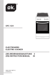
9. Mounting the appliance
For the installation of the appliance, there must be a free space as indicated in Fig. 1 – 6,
depending on the individual model (see type plate on appliance). The installation location
is limited only as follows:
there must be a distance of at least 400 mm between the cooktop and any furniture above
(e.g. hanging cabinets).
The appliance rests on the frame in the kitchen furniture. It must be fastened firmly to the
kitchen countertop using the included screws and 4 fastening elements (see Figure 1). Do
not use the gas lines, taps or parts of the burner for fastening.
Beneath the bottom of the appliance there must be a space of at least 10 mm in order to
provide for sufficient circulation of the cooling air.
To exhaust the heat under the cooktop it is needed to have ventilation openings of a
minimum free cross section of 7,5 cm2 underneath the cooktop. The minimum width of the
ventilation openings is 5 mm, that means the opening dimension has to be minimum 150 x
5 mm.
The position of the ventilation openings can be according to the built-in-situation on the
side, at the front, at the back or underneath the appliance.
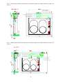
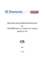
Fig. 1 Cutout in the kitchen countertop
10
Fig. 2 Exhaust gas and fresh air inlet flues, horizontal right rear (outside wall flue system, see
Fig. 6)
Truma flue pipe 80
Art.no. 39580-00
Cramer air inlet pipe
30
Cramer outside double flue
Truma flue pipe
55
Art.no. 39320-00
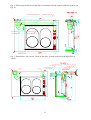
Fig. 3 Exhaust gas and fresh air inlet flues, horizontal right side (outside wall flue system, see
Fig. 6)
Cramer outside double flue
Truma flue pipe
55
Art.no. 39320-00
Truma flue pipe
80
Art.no. 39580-00
Cramer air inlet pipe
11
30
Fig. 4 Exhaust gas and fresh air inlet flues, horizontal left side (outside wall flue system, see
Fig. 6)
Cramer outside double flue
Truma flue pipe 80
Art.no. 39580-00
Cramer air inlet pipe
30
Truma flue pipe 55
Art.no. 39320-00
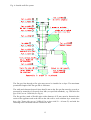
Fig. 5 Exhaust line, left vertical. Fresh air flue line, vertical from below through floor of
vehicle
Cramer air inlet pipe
Cramer tube 30
Air outlet
Air inlet
Truma floor flue BK 24
Art.no. 39061-00
30
Truma roof flue Art.no. 30700-03
Truma flue pipe
Art.no. 39580-00
Truma flue piper 55
Art.no. 39320-00
12
80
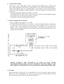
Fig. 6 Outside wall flue system
The flue gas line through a flue pipe must never be installed at a slope. The maximum
permissible length of the flue gas line is 2000 mm.
The walls and elements located closer than 50 mm to the flue gas line must be covered or
protected by materials of fireproof class M0 (see specified standards), e.g. TRUMA flue
pipe ∅ 80, art. no. 39580-00 (see Fig. 6).
The flue gas line, made of flexible pipe with a diameter of 55 mm, must be fastened at the
outlet of the appliance and at the inlet to the side wall or roof ventilator by a worm drive
hose clip (Truma clip art. no. 39590-00 for a pipe with 50 – 60 mm ∅) and with the
fastening screws included with the Truma roof flue.
13
The air inlet line, made of flexible metal pipe with a diameter of 30 mm (Cramer), must
be fastened at the air inlet of the appliance and at the Cramer outside double flue
according to Figures 2, 3 and 4 with a worm drive hose clip, 25 – 40 mm ∅ (Cramer).
10. Do not install the appliance near highly flammable materials.
11. Removing the appliance from the furniture
- Close main gas valve
- Remove fastening screws
- Disconnect gas connection and any electric cables
12. Technical data and CE approval number
a) Technical data:
- Glass ceramic cooktop: model CC05
- Appliance category: I3
- Output: 3.3 kW
- Gas consumption: 240 g/h, propane/butane
- Electric power supply: DC +12 V, 5 A
- Date: 09/2005
b) CE approval number: CE-0085BQ0092
Service by the manufacturer:
DOMETIC CRAMER SR s. r. o.
● Tehelná 8 ● SK – 986 01 Fiľakovo ● Phone: +421-47 4319100 ●
● Fax: +421-47 4319144, 4319166 ●
● E-mail: [email protected] ●
● Internet: www.cramer.sk ● www.dometic.com ●
14