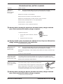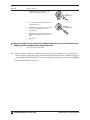
1
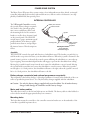
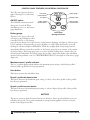
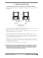
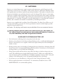
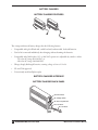
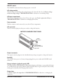
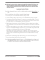
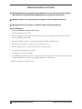
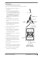
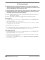
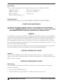
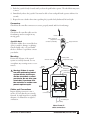
METRO® POWER III POWER WHEELCHAIR Owner’s manual GF0600059RevB06 ©GF Health Products, Inc. November 2006 IMPORTANT: Read this manual before operating your Metro Power III Power Wheelchair. Save this manual for later use. Contents I Introduction..........................................................................................................3 II Safety Precautions............................................................................................4 III Handling Tips........................................................................................................9 IV Getting Started.................................................................................................12 V Operating Instructions..................................................................................15 VI Adjustments.......................................................................................................16 VII Batteries.............................................................................................................21 VIII Maintenance.....................................................................................................29 IX Troubleshooting..............................................................................................34 X Transporting the Metro Power III.............................................................39 XI Limited Warranty..............................................................................................40 XII Index.......................................................................................................................42 GF Health Products, Inc. is not responsible for typographical errors. Packaging, warranties, specifications and products are subject to change without notice. GF0600059RevB06, November 2006 Metro Power III Owner’s Manual I Introduction Important safety, operating, and maintenance instructions that warrant your attention are included in this owner’s manual. Read the entire manual carefully before operating your new wheelchair, and refer to it as often as necessary to help maintain good performance standards. Consult your healthcare professional and qualified Graham-Field dealer for assistance in developing and learning safe and effective techniques to perform your daily activities according to your individual physical abilities and needs, and to make certain that your wheelchair is properly prescribed and adjusted for your use. The safety precautions in this manual are general warnings intended to be used only as basic guidelines. You may find it necessary to develop your own methods for safely solving frequently encountered challenges. Again, consult your professional medical advisors for their recommendations about safety methods, and never hesitate to ask for their assistance. Your wheelchair should receive frequent, regularly scheduled maintenance, including an inspection of the mechanical parts, to ensure proper operation. Some suggested inspection procedures, troubleshooting procedures, and adjustment procedures are included in this manual. When it comes to service and repair, remember that your Graham-Field dealer knows your wheelchair best. All information and specifications in this manual are current at the time of printing. However, because it is Graham-Field policy to continually improve the quality and reliability of all our products, we reserve the right to make changes at any time without notice. Thank you for choosing an Everest & Jennings product. We at Graham-Field wish to assure you of our continuing commitment to provide innovation and quality in our product. The Metro Power III is a light duty power wheelchair with programmability features that adjust driving control parameters to best suit the user’s current driving requirements and adapt to the user's evolving needs over time. It is suitable for frequent users who require a power wheelchair fitted to their specific anatomy and best suited for indoor and limited outdoor use. Its ease of disassembly allows for easy transportation. The Metro Power III’s maximum weight capacity is 300 lb. (136 kg). The person performing adjustments on the Metro Power III has the responsibility of making certain that the user can safely operate the wheelchair with the adjustments selected. This person must evaluate the user’s ability, weight, physical condition, the environment in which the wheelchair will be used, and the terrain over which the wheelchair will travel. Graham-Field recommends the use of anti-tippers at all times. Please note the following special statements, used throughout this manual, and their significance: Note: Special information set off from the text. s Caution: Damage to equipment is possible Warning: Personal injury could occur. Metro Power III Owner’s Manual GF0600059RevB06, November 2006 II Safety Precautions IMPORTANT: BEFORE USING YOUR Metro Power III, PLEASE READ AND UNDERSTAND THE FOLLOWING SAFETY PRECAUTIONS. Maintenance Protect your Metro Power III by having it serviced regularly. Whenever any part of your wheelchair is not functioning properly, a hazardous situation could result. Only excellent condition is acceptable where safety is concerned. Periodic inspection, adjustment, and replacement of worn parts will provide many years of superb performance. Many phases of maintenance are best performed by a qualified Graham-Field dealer. We recommend the use of only Graham-Field replacement parts. Warnings Warning: The wheelchair user must be capable of driving a power wheelchair safely. Warning: Do not operate this wheelchair on streets or roadways. Warning: Do not operate this wheelchair on hilly or rough terrain, sand, wet or icy surfaces, or surfaces with impaired traction. Warning: Do not attempt inclines without anti-tippers installed. Do not attempt any incline or decline greater than six degrees (10% grade, or one foot of rise or fall per ten feet of ramp length). Wet or icy surfaces, or surfaces with impaired traction, may cause loss of control. Warning: During descent, the lowest part of the footplate extensions should be no closer to the ground than 2 1/2 inches, to permit proper clearance at the bottom of the incline. Warning: Do not turn wheelchair while going downhill. Warning: This wheelchair does not offer seating or occupant restraint equivalent to the seat provided in a motor vehicle! To increase your safety while traveling in a motor vehicle, always transfer to the vehicle seat and use the restraint provided by the vehicle manufacturer. Warning: Do not tie down or attach anything to the wheels. This could cause tipping and possibly result in injury or damage to the wheelchair. Warning: When using a wheelchair lift, engage the rear wheel levers and turn the wheelchair power switch OFF. GF0600059RevB06, November 2006 Metro Power III Owner’s Manual Warning: Do not enter or exit the wheelchair without first turning the wheelchair power switch OFF, and ensuring that the drive engagement levers are engaged, to prevent wheelchair movement. Warning: Operate only with anti-tippers in place. Warning: Disengaging the rear wheel levers will also disengage the electromechanical park brakes and allow the wheelchair to roll. Warning: Do not lean over the top of the wheelchair back. This could cause the wheelchair to tip. Warning: Before leaning or reaching forward: To reduce the risk of tipping, sit back in the seat and rotate casters fully toward front of wheelchair. Warning: Do not stand or step on the footplates while transferring to or from your wheelchair. This could cause the wheelchair to tip. Warning: Ensure that no water, moisture, or other liquid enters the integral controller. Warning: The integral controller programs should be adjusted only by a qualified therapist or technician. This person must evaluate the user’s ability, weight, and physical condition, the environment in which the wheelchair will be used, and the terrain over which the wheelchair will travel. A wide range of adjustment and versatility is provided so that the requirements of many different abilities may be met, and the person setting the driving characteristics has the responsibility of making certain that the user can safely operate the wheelchair at the speed and rates selected. Warning: When adjusting with the programmer, start with a slow (low number) standard program or factory setting. Increase only if the user has the ability to control the wheelchair safely. Warning: When adjusting with the programmer, use caution when changing the individual parameters to a setting different than that provided by the factory setting. Warning: When adjusting with the programmer, do not set reverse speed faster than forward speed. Warning: Ensure that wheelchair power is off before connecting or disconnecting the programmer. Metro Power III Owner’s Manual GF0600059RevB06, November 2006 Warning: Do not switch programmer into PROGRAM mode while wheelchair is moving. Warning: Do not disconnect the wheelchair batteries while the programmer is connected to the integral controller. Warning: Do not use any adaptive control devices other than those provided or recommended by Graham-Field. Warning: Do not connect accessories to the batteries; it will decrease driving range and shorten battery life. Do not connect ANYTHING to only one battery; this will cause premature battery failure. Warning: Never connect a respirator or other life-support device to the wheelchair batteries, since it will shorten the battery operating time. This could cause an unanticipated failure of both the wheelchair and the life-support equipment. Warning: Unauthorized modification could create a hazardous condition, which could result in serious injury. Warning: The use of non-Graham-Field replacement parts could create a hazardous condition, which could result in serious injury. Warning: Standard weight capacity for the Metro Power III wheelchair is 300 lb. (136 kg). Warning: Do not tow any loads or “piggyback” passengers or heavy packages. Warning: Keep all cables away from the moving parts of the wheelchair. Warning: As a safety feature, this wheelchair is equipped with fail-safe electromechanical park brakes. Any interruption in the power supply will cause these brakes to immediately engage and stop the wheelchair. If the occupant is not properly positioned, an unanticipated stop could pitch the occupant forward and out of the wheelchair. Review the owner’s manual and consult with your dealer regarding proper positioning and use of this wheelchair. Warning: Graham-Field specifically disclaims responsibility for any bodily injury or property damage which may occur during any use which does not comply with federal, state or local laws or ordinances. GF0600059RevB06, November 2006 Metro Power III Owner’s Manual Electromagnetic interference (EMI) from radio wave sources It is very important that you read this information regarding the possible effects of electromagnetic interference on your Everest & Jennings Metro Power III power wheelchair. Powered wheelchairs may be susceptible to electromagnetic interference (EMI), which is interfering electromagnetic (EM) energy emitted from sources such as radio stations, TV stations, amateur radio (HAM) transmitters, two-way radios, and cellular telephones. The interference (from radio wave sources) can cause the powered wheelchair to release its brakes, move by itself, or move in unintended directions. It can also permanently damage the powered wheelchair’s control system. The intensity of the interfering EM energy can be measured in volts per meter (V/m). Each powered wheelchair can resist EMI up to a certain intensity. This is called its “immunity level”. The higher the immunity level, the greater the protection. At this time, current technology is capable of achieving at least a 20 V/m immunity level, which would provide useful protection from the more common sources of radiated EMI. This powered wheelchair model has an immunity level of 20 V/m when tested with Integral Controller Part Number 90762330. Be aware that using different components, adding accessories, or modifying the powered wheelchair may change the immunity level. There are a number of sources of relatively intense electromagnetic fields in the everyday environment. Some of these sources are obvious and easy to avoid. Others are not apparent and exposure is unavoidable. However, we believe that by following the warnings that follow, your risk to EMI exposure will be minimized. The sources of radiated EMI can be broadly classified into three types: 1) Hand-held portable transceivers (transmitters-receivers) with the antenna mounted directly on the transmitting unit. Examples include: citizens band (CB) radios, “walkie talkies”, security, fire, and police transceivers, cellular telephones, and other personal communication devices. Note: Some cellular telephones and similar devices transmit signals while they are on, even when not being used; 2) Medium-range mobile transceivers, such as those used in police cars, fire trucks, ambulances, and taxis. These usually have the antenna mounted on the outside of the vehicle; and 3) Long-range transmitters and transceivers, such as commercial broadcast transmitters (radio and TV broadcast antenna towers) and amateur (HAM) radios. Note: Other types of hand-held devices, such as cordless telephones, laptop computers, AM/FM radios, TV sets, CD players, and cassette players, and small appliances, such as electric shavers and hair dryers, so far as we know, are not likely to cause EMI problems with your powered wheelchair. Metro Power III Owner’s Manual GF0600059RevB06, November 2006 Powered Wheelchair Electromagnetic Interference (EMI) Because EM energy rapidly becomes more intense as one moves closer to the transmitting antenna (source), the EM fields from hand-held radio wave sources (transceivers) are of special concern. It is possible to unintentionally bring high levels of EM energy very close to the powered wheelchair’s control system while using these devices. This can affect powered wheelchair movement and braking. Therefore, the warnings that follow are recommended to prevent possible interference with the control system of the powered wheelchair. EMI Warnings Electromagnetic interference (EMI) from sources such as radio and TV stations, amateur radio (HAM) transmitters, two-way radios, and cellular telephones can affect powered wheelchairs. Following the warnings listed below should reduce the chance of unintended brake release or powered wheelchair movement which could result in serious injury. Warning: Do not operate hand-held transceivers (transmitters-receivers), such as citizens band (CB) radios, or turn on personal communication devices, such as cellular telephones, while the powered wheelchair is turned on. Warning: Be aware of nearby transmitters, such as radio or TV stations, and try to avoid coming close to them. Warning: If unintended movement or brake release occurs, turn the powered wheelchair off as soon as it is safe. Warning: Be aware that adding accessories or components, or modifying the powered wheelchair, may make it more susceptible to EMI (Note: There is no easy way to evaluate their effect on the overall immunity of the powered wheelchair). Warning: Report all incidence of unintended movement or brake release to GrahamField, and note whether there is a source of EMI nearby. Important Information 1) 20 volts per meter (V/m) is a generally achievable and useful immunity level against EMI (as of May 1994) (the higher the level, the greater the protection); 2) The immunity level of this powered wheelchair model is listed on page 7. Be aware that using different components, adding accessories, or modifying the powered wheelchair may change the immunity level. GF0600059RevB06, November 2006 Metro Power III Owner’s Manual III Handling Tips The Everest & Jennings Metro Power III been designed and engineered to perform as a stable and well balanced unit when used for its intended purpose. However, it is possible to tip the Metro Power III over if it is used improperly. We urge you to learn the characteristics of your wheelchair. It is most important to learn safe methods to perform the daily activities basic to your lifestyle. Consult your medical professionals for assistance in developing the skills and proper techniques to perform all activities safely. BALANCE Proper balance is the key to maintaining the stability of your wheelchair. Reaching, bending, and transferring to or from a wheelchair will change the weight distribution and center of gravity of you and your wheelchair. When performing such activities, do so as instructed in the following paragraphs to avoid tipping the wheelchair. TRANSFER ACTIVITIES Warning: Always ensure that wheelchair is on a stable, level surface, engage the drive engagement levers, and turn the wheelchair power switch OFF before transfer. Warning: Do not step on the footplates; this could cause the wheelchair to tip. Fold them up, and either detach them, or swing them aside. There is a critical moment when there is little or no seat platform beneath you. Take every precaution to reduce this unsupported distance before you attempt transfer. Transferring to or from a wheelchair is a very difficult maneuver. Exercise extreme care when transferring without the aid of either an attendant or a patient lift. Consult your physician, nurse, or physical therapist for assistance in developing your individual technique. Make sure that the wheelchair is stabilized, and will not move or slide during the transfer. Take extra precaution to prevent tipping. Use good body mechanics to prevent personal injury. REACHING / BENDING Warning: Always turn the casters frontward to provide stability while reaching. If in doubt, ask for assistance or use a device that will extend your reach without requiring you to shift your weight. Although it is not recommended, you may find it occasionally necessary to lean or reach from your wheelchair. Consult with your healthcare professional for assistance in developing your personal safe reaching or moving techniques suited to your ability and restrictions. Metro Power III Owner’s Manual GF0600059RevB06, November 2006 Reaching / bending forward or sideward Warning: Do not attempt to reach objects if you are required to move forward in the seat. Do not attempt to retrieve objects from the floor if you must reach down between your knees. Do not shift your weight in the direction that you are reaching and/or bending; this could cause the wheelchair to tip. 1. Maneuver the wheelchair as close as possible to the object you wish to reach. 2. Rotate both casters fully forward. If otherwise, go forward and then back the wheelchair toward the object to swing the casters fully forward. 3. Ensure that the casters are rotated fully forward before reaching. If not, repeat step 1. Reaching / bending backward Warning: Do not lean over the back upholstery; this could cause the wheelchair to tip. 1. Maneuver the wheelchair as close as possible to the object. The rear wheels will limit how close you can get. 2. Rotate both casters fully forward. If otherwise, go forward and then back the wheelchair toward the object to swing the casters fully forward. 3. Reach only as far as your arm will extend without changing your sitting position. If in doubt, reposition the wheelchair or ask for assistance. Ramps and Inclines Warning: During descent, the lowest part of the footplate extensions should be no closer to the ground than 2 1/2 inches, to permit proper clearance. Warning: Do not attempt inclines without anti-tippers installed. Do not attempt any incline or decline of more than 6 degrees (10% grade, or one foot of rise or fall per ten feet of ramp length). Warning: If equipped with wheel locks—do not use the locks to slow your descent. Attempting to use wheel locks is likely to result in accidental locking that could cause the wheelchair to stop abruptly, suddenly pitch forward, or tip sideways. Warning: Avoid changing direction while descending a ramp or incline, as this could cause instability. Most people are capable of negotiating short inclines without assistance, depending upon upper body strength, endurance, and the degree of incline. Know your own capabilities and limitations in terms of strength and endurance before attempting to negotiate an incline or decline. Practice with an attendant or healthcare professional first before attempting any inclines, declines curbs or ramps. 10 GF0600059RevB06, November 2006 Metro Power III Owner’s Manual Always inspect the ramp for hazards such as holes, slippery or uneven surfaces, etc. before starting up or down. If you can not see the entire ramp, ask someone to inspect it for you. Ascent Lean the upper part of your body slightly forward as you ascend the incline. If it becomes necessary to stop on the incline, avoid any sudden forward movement as you resume climbing; this could cause tipping. Descent Always face forward when going down a ramp, but DO NOT lean forward; this could cause the wheelchair to tip. If possible, lean slightly backward to increase stability. It is critical to keep the wheelchair under control at all times. Descent should be made slowly and steadily, allowing the wheelchair’s control system to maintain a safe speed. Upon stopping, electromechanical park brakes will engage to prevent the wheelchair from rolling. CURBS AND STEPS Curbs, steps and stairways are dangerous obstacles that confront the wheelchair user. When you encounter curbs, try to find a way around, or use the ramps now available in most locations. If you encounter steps and there is no ramp available, try to avoid the steps by utilizing the disabled designated elevators now required in most locations. Warning: Never attempt to negotiate curbs, steps, stairs or escalators in your Metro Power III. Metro Power III Owner’s Manual GF0600059RevB06, November 2006 11 IV Getting Started The Metro Power III is designed to provide the highest degree of independence and mobility. The tested range of the Metro Power III is approximately 16 miles on a hard level surface (tested with a 250 lb. user and fully charged U1 size batteries). Actual range will vary according to your weight, the amount of start/stop driving, ambient temperature, and the terrain on which you travel with your wheelchair. As you become more acquainted with your wheelchair, its range and performance capabilities will become more apparent. The Metro Power III is illustrated below. Main features are identified. Back Upholstery Push handle/handgrip Arm Joystick Integral Controller Seat Cushion Seat Upholstery Wheel Lock Front rigging (footrest) Leg Strap Rear Wheel Motor Battery Box & Battery Tray 12 GF0600059RevB06, November 2006 Footplate Caster Crossbrace (Serial Number Label) Metro Power III Owner’s Manual Power Drive System The Metro Power III power drive system consists of two independent rear drive wheels, an integral controller, independent, direct drive right and left motors, and two twelve volt batteries (not supplied by Graham-Field) that provide power. Integral controller battery box connector W R E motor connector O P The VSI Integral Controller contains the joystick, battery charger receptacle (also used for the optional programmer), motor and battery cables, and the mounting holes for the extension bracket, as well as those features found on the control panel: The ON/OFF switch, battery gauge, maximum speed/ profile indicator, horn button, speed/ profile decrease button, and speed/profile increase button. Their descriptions follow. joystick control panel mounting holes battery charger/ programmer receptacle VSI integral controller * * VSI is a trademark of PG Drives Technology, Inc. Joystick The JOYSTICK controls the speed and direction of wheelchair travel. The further you push the joystick from the rest position the faster your wheelchair will move. When the joystick is returned to the neutral (center) position or released, the control system will bring the wheelchair to a smooth stop. Upon stopping, electromechanical park brakes will engage to prevent the wheelchair from rolling. Moving the joystick forward (away from the user) causes the wheelchair to move forward. Moving the joystick back (toward the user) causes the wheelchair to travel in reverse. When the joystick is moved right to 3 o’clock position, the wheelchair will turn to the right; when the joystick is moved left to 9 o’clock position, the wheelchair will turn to the left. Battery charger receptacle (and optional programmer receptacle) The receptacle for the battery charger / optional programmer is located on the underside of the controller as specified in picture above. Use only the battery charger supplied with the wheelchair. s Caution: Use only the battery charger supplied with your wheelchair. Use of another battery charger could damage the Controller and the battery charger. Motor and battery cables The cables that connect to the left and right motors are labeled. The battery cable is either labeled or color-coded to match the appropriate battery box connector. Mounting holes The holes that mount the controller to the controller extension bracket are on the underside of the controller as specified in picture above. Metro Power III Owner’s Manual GF0600059RevB06, November 2006 13 Control panel features, VSI integral controller The VSI control panel is shown at right. A description of each feature follows. ON/OFF switch The ON/OFF switch turns wheelchair power on and off. When wheelchair power is on, the battery gauge illuminates. max speed / profile indicator battery gauge horn button ON/OFF switch speed / profile decrease button speed / profile increase button control panel Battery gauge VSI integral controller The three-color (green, yellow and red) battery gauge illuminates when controller power is on. The battery gauge shows the charge level of the batteries. As the batteries discharge, the lights go off from green to red, similarly to an automobile’s gas gauge (all lights on = full). When the batteries are nearly discharged, only the red lights will illuminate. When the red lights flash slowly, charge batteries immediately. When you turn the controller on, the battery gauge shows an estimate of the remaining battery charge. The battery gauge gives you a more accurate reading about a minute after you start driving the wheelchair. The battery gauge also provides a diagnostics display when wheelchair electrical system problems occur. See TROUBLESHOOTING for a description of the battery gauge diagnostics. Maximum speed / profile indicator This is a 5-segment display which indicates the maximum speed setting or which drive profile is selected (if drive profiles have been programmed). Horn button This button operates the wheelchair’s horn. Speed / profile decrease button This button decreases the maximum speed setting (or selects a lower drive profile, if drive profiles have been programmed). Speed / profile increase button This button increases the maximum speed setting (or selects a higher drive profile, if drive profiles have been programmed). Motors The motors operate in both the forward and reverse direction. Motor speed and direction are controlled by the joystick. The joystick commands are interpreted and applied to the motors by the circuits of the integral controller. 14 GF0600059RevB06, November 2006 Metro Power III Owner’s Manual V Operating Instructions Read and understand all Safety Precautions before operating your wheelchair. 1. Charge the batteries fully before use. For installation and charging information, refer to Part VII, BATTERIES. drive engagement levers outward rear wheels disengaged drive engagement levers inward rear wheels engaged engage rear wheels (rear of wheelchair shown) 2. Engage the rear wheels by turning the drive engagement levers (on the tops of the motors at rear of wheelchair) inward, toward the battery boxes; see picture above. 3. With the joystick in neutral, turn wheelchair power on (press the ON/OFF switch). The battery gauge will blink and then turn on after a second. 4. Select a low speed. Move the joystick gently in the direction in which you wish to travel. 6. To stop the wheelchair, release the joystick to the neutral (center) position. The control system will bring the wheelchair to a smooth stop. Upon stopping, electromechanical park brakes will engage to prevent the wheelchair from rolling. 7. Attempting to overcome a stall condition may trip one of the circuit breakers, located in each of the battery box lids. In the event of an overload, the circuit breaker will pop out. To reset the circuit breaker, push the button in. 8. Keep all cables away from the moving parts of the wheelchair. Warning: In the event of the wheelchair moving in an unexpected way, release the joystick. This action will stop the wheelchair. Do not use the integral controller’s ON/OFF switch to stop the wheelchair, except in case of emergency, or you may shorten the life of the wheelchair drive components. Metro Power III Owner’s Manual GF0600059RevB06, November 2006 15 VI Adjustments The Metro Power III offers several adjustments to enhance driving ease and comfort. Adjustments should be performed with wheelchair power off and the wheelchair unoccupied. Ensure that all components are in excellent condition before adjusting (Part VIII, MAINTENANCE, offers suggestions for maintaining your wheelchair in excellent condition). These adjustments are recommended methods; after performing a few, you may develop your own. Specific tools needed to perform each adjustment are identified in adjustment sections. A complete list of tools needed to perform all adjustments in Part VI follows: 7/32" hex key, 3/16" hex key Arms Flip arm back The Metro Power III arm can be removed from the front socket and rotated around the back socket. To flip the arm back: 1. Press arm release at front socket and pull arm up until locking button is free (see picture at right). 2. Rotate arm backward around pivot. If integral controller is attached to arm, take care that it is not allowed to drop. pivot release 3. Replace arm assembly: rotate arm frontward around pivot. Lower arm straight down into front socket and push to lock. Ensure that locking button is locked into place. locking button flip arm back Warning: Ensure that arm is rotated back down to front and locked in place in front arm socket before operating wheelchair. Adjust integral controller extension position—backward & forward The integral controller extension can be moved backward and forward along arm. The extension has a stop at both front and back limits to keep it from adjusting too far backward or forward. 1. Release the clamp. arm 2. Slide extension to preferred position. 3. Resecure the clamp. Warning: Ensure that extension is securely mounted before operating wheelchair. extension integral controller clamp bracket clamp release adjust extension position 16 GF0600059RevB06, November 2006 Metro Power III Owner’s Manual Footrest—detachable, swingaway Warning: The lowest part of the footplate extensions should be no closer to the ground than 2 1/2 inches (5.5 cm), to permit proper clearance. Warning: Do not stand on the footplates; this could cause the wheelchair to tip. Remove footrest 1. To release lock, pull swingaway release lever forward, toward front of wheelchair. Footrest will swing outward. hinge plate 2. To detach, lift footrest straight up. Attach footrest 1. Set footrest on wheelchair (so that footrest hinge plates engage wheelchair hinge pins). swingaway release lever 2. Swing footrest inward. 3. Ensure that footrest is locked in place and that swingaway release lever is locked in a rearward position, toward back of wheelchair. footrest (left shown) detachable, swingaway Adjust footrest length 7/32" hex key To adjust footrest length, you will loosen the clamp that holds the footplate extension inside the footrest hanger. 1. Loosen footrest clamp: use a 7/32" hex key to loosen clamp enough so that footplate extension tube slides inside footrest hanger tube. 2. Reposition footplate extension in desired position. 3. Tighten footrest clamp: use a 7/32" hex key to resecure clamp. footrest hanger tube clamp footplate extension tube 4. Follow steps 1-3 to adjust other footplate. 5. Ensure that both clamps are securely fastened and that minimum ground clearance is 2 1/2 inches. Metro Power III Owner’s Manual adjust footplate extension length (left shown) GF0600059RevB06, November 2006 17 Elevating legrest—detachable, swingaway Warning: The lowest part of the footplate extensions should be no closer to the ground than 2 1/2 inches (5.5 cm), to permit proper clearance. Warning: Do not stand on the footplates; this could cause the wheelchair to tip. Remove elevating legrest 1. To release lock, pull swingaway release lever forward, toward front of wheelchair. Legrest will swing outward. hinge plate 3. To detach, lift legrest straight up. Attach elevating legrest 1. Set legrest on wheelchair (so that legrest hinge plates engage wheelchair hinge pins). 2. Swing legrest inward. 3. Ensure that legrest is locked in place and that swingaway release lever is locked in a rearward position, toward back of wheelchair. swingaway release lever elevating legrest (upper part only shown— legrest may not appear exactly as shown) legrest release lever Adjust legrest elevation Note: It is possible to raise elevating legrest without unlocking legrest release. As a safety feature, however, in order to lower legrest, you must unlock legrest release. 1. To release lock, pull legrest release lever up toward back of wheelchair. 2. Raise legrest to desired position. 3. Lock legrest: Push legrest release lever toward front of wheelchair. elevating legrest, left shown (may not appear exactly as shown) 18 GF0600059RevB06, November 2006 Metro Power III Owner’s Manual Adjust elevating legrest footplate extension length 7/32" hex key To adjust footplate extension length, you will loosen the clamp that holds the footplate extension inside the legrest hanger. 1. Loosen legrest hanger clamp: use a 7/32" hex key to loosen clamp enough so that footplate extension tube slides inside legrest hanger tube. clamp 2. Reposition footplate extension in desired position. legrest hanger tube footplate extension tube 3. Tighten legrest hanger clamp: use a 7/32" hex key to resecure clamp. 4. Follow steps 1-3 to adjust other footplate. 5. Ensure that both clamps are securely fastened and that minimum ground clearance is 2 1/2 inches. adjust legrest footplate extension length (left shown) Adjust elevating legrest pad position up or down The legrest pad has three possible positions, adjustable in one-inch increments. To adjust: legrest tube pad/ hinge plate assembly 1. Rotate pad/hinge plate assembly on legrest tube so that legrest tube stop is in center of hinge plate slot. legrest tube stop 2. Slide pad/hinge plate assembly up or down legrest tube to desired position. 3. Rotate pad/hinge plate assembly on legrest tube so that legrest tube stop is aligned in desired position. Metro Power III Owner’s Manual hinge plate slot leg panel elevating legrest (footplate extension not shown) GF0600059RevB06, November 2006 19 Adjust wheel locks 3/16" hex key Note: Check the tire pressure before adjusting the wheel locks—tires should be properly inflated before adjusting. 1. Place the wheel lock in the OFF (unlocked) position. 2. Loosen the wheel lock clamp: use 3/16" hex key to loosen, but not remove the two bolts that secure the wheel lock clamp to the side frame. You should be able to slide the clamp, but not pull it off the sideframe. 3. Place the wheel lock in the ON (locked) position. lever bolt clamp lock adjust wheel lock 4. Slide the lever assembly back until the lock is touching the tire surface. 5. Place the wheel lock in the OFF (unlocked) position; move the clamp 1/4 inch closer to the tire. 6. Without moving the wheel lock assembly, tighten the mounting bracket bolts. 7. Repeat steps 1-6 for other wheel lock. Warning: After adjustment and before using wheelchair, check both wheel locks to ensure that the wheel locks will prevent the wheels from moving. Warning: If a wheel lock becomes worn or damaged, replace it immediately. 20 GF0600059RevB06, November 2006 Metro Power III Owner’s Manual VII Batteries Batteries are of critical importance, require attention and maintenance, and will require periodic replacement. As batteries age, their ability to hold a charge decreases. Old batteries discharge much more quickly than new batteries under the same driving conditions. This results in a decrease in the distance the wheelchair can travel before batteries need to be charged. This decrease is often misinterpreted as a problem with the wheelchair system, when in fact the batteries have simply reached the end of their useful lives and should be replaced. Properly maintained batteries can be expected to last approximately 9 to 18 months. The purpose of proper maintenance is to extend that life as much as possible, and to minimize the incidence of unsatisfactory wheelchair performance. Batteries are not supplied with your Metro Power III wheelchair. The Metro Power III uses two 12 volt deep cycle batteries, group size U1. For best performance, batteries with the highest possible amp/hour rating should be used. s Caution: Use only deep cycle batteries on your wheelchair. Do not use automotive batteries. Warning: Batteries generate sulfuric acid, which can burn eyes, skin, clothes, etc. Use caution! Always wear safety glasses when working with batteries. If contact occurs, flush immediately with water and get medical attention. Guidelines to extending battery life • Give the batteries a full charge before using them for the first time. • Limit use of new batteries for the first ten charge/discharge cycles—avoid deeply discharging the batteries. New batteries are not capable of their rated output until they have been discharged a number of times. • Recharge batteries after every discharge. Discharging batteries deeply before recharging them will shorten battery life. Leaving partially discharged batteries idle for several days is not recommended; charge them as soon as possible after discharging. • Charge batteries fully each time before using. Allow the charger to finish its charge cycle once started. This will help prevent deeply discharging the batteries. Unlike some rechargeable batteries, the batteries used on wheelchairs do not exhibit a significant “memory effect”—they will recharge to their full capacity, even if only partially discharged before each charge. • If you must store your wheelchair for a long period of time, charge the batteries weekly. • Perform regular maintenance on the batteries. See maintenance schedule in Section VIII, MAINTENANCE, for recommended regularity. Metro Power III Owner’s Manual GF0600059RevB06, November 2006 21 Battery Charger Battery Charger Features 115 SE FU The 4 amp switch-mode battery charger has the following features: • Compatible with gel cell lead acid, sealed lead acid, and unsealed lead acid batteries. • Can be left connected indefinitely after charging without harming the batteries. • Compatible with 50/60 cycles. 115 or 220 VAC operation is adjustable by switch to either: 115 volts AC (range 90-130 VAC) or 230 volts AC (range 180-260 VAC). • Charges deeply discharged batteries, starting voltage as low as 1/2 volt. • UL and CSA approved. • Conveniently small and light weight. Battery Charger Interface Battery charger back panel ON/OFF switch AC voltage switch 115 AC fuse compartment line connector AC connector back panel 22 GF0600059RevB06, November 2006 Metro Power III Owner’s Manual ON/OFF switch The ON/OFF switch turns battery charger power on and off. AC voltage switch The AC voltage switch changes the voltage between 115 volts and 230 volts. See Battery voltage switch on wrong setting in TROUBLESHOOTING for directions on switching voltage. AC fuse compartment The AC fuse compartment houses the AC fuse and a spare. See Check / replace the AC fuse in TROUBLESHOOTING for directions on changing the AC fuse. Line connector The line connector can be removed to access the AC fuse compartment. AC connector The AC connector plugs into the power outlet to charge the batteries. Battery charger front panel output connector SE FU red LED charge indicator (yellow & green) LED front panel output fuse Output connector The output connector plugs into the wheelchair battery charger receptacle to charge the batteries. Red LED The red LED shows power on (battery charger plugged into power outlet and ON/OFF switch turned on). Charge indicator (yellow & green) LED The charge indicator LED illuminates yellow when charging, and changes to green when the batteries are fully charged. The charge indicator LED may flicker between green and yellow before finally turning green, especially when charging older batteries. Output fuse See Check / replace the output fuse in TROUBLESHOOTING for directions on changing the output fuse. Metro Power III Owner’s Manual GF0600059RevB06, November 2006 23 Battery Charger Safety Warning: Do not use a household extension cord if the charger plug does not reach the power outlet. Use of an improper extension cord could result in fire and electric shock. If an extension cord must be used, use a three conductor No. 16 AWG (or heavier) cord with ground, properly wired, in good electrical condition, and keep it as short as possible. Warning: Do not use cords that are damaged or defective. Use of a damaged or defective cord could result in fire or electric shock. Warning: Locate all battery charger cords so that they will not be stepped on, tripped over, or otherwise subjected to damage or stress. Warning: To prevent electrical shock, do not touch uninsulated parts of the battery charger output connector, battery connectors, or battery terminals. Ensure that all electrical connectors are in good working condition. Do not use connectors that are cracked, corroded, or do not make adequate electrical contact. Use of a damaged or defective connector could result in fire or electric shock. Warning: Ensure that area around battery charger and batteries is well ventilated while batteries are being charged. Do not allow clothing, blankets, or other material to cover battery charger. Do not place under a bed. Warning: Keep sparks, flame, and smoking materials away from batteries at all times. No smoking! Warning: Battery chargers can ignite flammable materials and vapors. Do not use near fuels, grain dust, solvents, thinners, or other flammables. Warning: Batteries generate gases which can be explosive. To prevent arcing or burning near batteries, do not disconnect battery charger output connector from wheelchair battery charger receptacle when battery charger is operating. If charge cycle must be interrupted, move the battery charger ON/OFF switch to OFF and disconnect the battery charger AC connector from power outlet, then disconnect battery charger output connector from wheelchair battery charger receptacle. Warning: To avoid damage to any of the battery charger connectors and their cords, disconnect by grasping the plug body and pulling it straight out of the outlet or receptacle. DO NOT pull on the cord. DO NOT twist, rock or pull the connector sideways. 24 GF0600059RevB06, November 2006 Metro Power III Owner’s Manual Warning: Do not use battery chargers not supplied by Graham-Field. Battery chargers not supplied by Graham-Field could damage the controller and the battery charger. Electrical arcing could result, which could cause severe personal injury, explosion, and fire. Charging the Batteries Note: Before charging the batteries, read the rest of this manual, especially the Battery Charger sections. Note: As a safety feature, the wheelchair is inoperable during charging. 1. Ensure that power to both wheelchair and battery charger is OFF. 2. Connect the battery charger output connector to the wheelchair battery charger receptacle. 3. North America: Plug the battery charger AC connector into a properly grounded, 115 volt, 60 cycle single phase power outlet. If you are not in North America, check that the battery charger AC voltage switch is set on the appropriate voltage for your location. 4. Place the battery charger power switch in ON position. The battery charger’s power indicator LED will illuminate red, the charge indicator LED will illuminate yellow, and the fan will begin to run. 5. The charge indicator LED may appear to flicker or alternate between green and yellow when the batteries are nearly finished charging, and the fan may go on and off. The charge-indicator LED will change to non-flashing green when the batteries are fully charged. Allow adequate time to bring the batteries up to a full charge—the actual time required to recharge the batteries will depend on discharge condition. The charger supplied with the wheelchair is automatic, and will not damage the batteries if left connected after batteries are fully charged. 6. When batteries are fully charged, place battery charger power switch in the OFF position. 7. Remove battery charger cable connector from receptacle. Note: If you have any problems charging the batteries, see Troubleshooting, battery charger in the TROUBLESHOOTING section. Identify the symptom and follow the steps in order. If you are unable to resolve the problem, contact your Graham-Field dealer. Metro Power III Owner’s Manual GF0600059RevB06, November 2006 25 Remove and Install Batteries Warning: Batteries can supply a large amount of current. Take care not to connect the terminals accidentally with anything metal; severe burns could result. Warning: Always wear safety glasses and gloves while working on batteries. Warning: Do not wear jewelry or watches while working on batteries. Remove Batteries Tools needed: Phillips screwdriver, 3/8” wrench 1. Switch wheelchair power OFF. 2. Remove strap that secures battery boxes to battery tray: loosen battery strap at back of rear battery box; pull up and forward. 3. Disconnect black connectors connecting integral controller and battery box. 4. Disconnect red connectors connecting the two battery boxes. 5. Remove battery boxes—from rear, lift up and over battery tray. 6. Loosen and remove battery box straps. 7. Carefully remove battery box lids. 8. Use a Phillips screwdriver and 3/8” wrench to remove nuts and screws that secure wire terminals to battery terminals. Set aside for reassembly. Repeat for other battery. 9. Remove batteries from battery boxes. 26 GF0600059RevB06, November 2006 Metro Power III Owner’s Manual Install Batteries Tools needed: Phillips screwdriver, 3/8” wrench Refer to picture at right for battery box and connector orientation. 1. Place battery in battery box. Repeat for other battery. 2. Connect wires in battery box lids: use a 3/8” wrench and provided hardware to secure red wire’s ring terminal to positive (+) battery terminal. Use a 3/8” wrench to secure black wire’s ring terminal to negative (-) battery terminal. Repeat for other battery. 3. Ensure that all wires are connected as specified. Ensure that all connections are secure. 4. Coat battery posts and terminals with petroleum jelly after all connections are made to retard corrosion. front of wheelchair cable to integral controller battery cable cable to right motor cable to left motor black connectors front battery box 5. Secure battery box lids on battery boxes. front battery 6. Secure battery box straps. 7. Position battery boxes on wheelchair as shown at right. From rear, lift up and over battery support rails. 8. Secure the red connectors to connect the battery boxes. 9. Secure the black connectors to connect the battery box and integral controller. 10.Ensure that the circuit breaker in each battery box lid is properly set by depressing its button. 11.Fasten strap that secures battery boxes to battery tray. 12.Do not attempt to operate the wheelchair unless batteries are installed as instructed. 13.Do not attempt to operate wheelchair until batteries are fully charged. Metro Power III Owner’s Manual red connectors rear battery box rear battery Metro Power III battery connections GF0600059RevB06, November 2006 27 Battery maintenance Warning: Batteries can supply a large amount of current. Do not wear jewelry or watches when working on batteries. Take care not to connect the terminals accidentally with anything metal; severe burns could result. Warning: Batteries contain sulfuric acid, which can burn eyes, skin, clothes, etc. Use caution! Always wear gloves when working with batteries. If contact occurs, flush immediately with water and get medical attention. s Caution: When cleaning batteries, do not let any baking soda solution enter the batteries; it will damage the electrolyte. s Caution: Always keep unsealed batteries upright so that the electrolyte doesn’t leak. Clean batteries 1. You will first need to remove the batteries; see Remove Batteries in previous REMOVE AND INSTALL BATTERIES section—follow steps 1-9. 2. Clean outside of batteries, and inside and outside of battery boxes, with a solution of one tablespoon baking soda to ten ounces water. 3. Rinse with clear water. Allow to dry. 4. Ensure that batteries and connectors are clean and dry. Reinstall batteries; see Install Batteries in previous REMOVE AND INSTALL BATTERIES section—follow steps 1-13. Clean battery terminals 1. You will first need to remove the batteries; see Remove Batteries in previous REMOVE AND INSTALL BATTERIES section—follow steps 1-8. 2. Clean all battery terminals and clamps with a wire brush (brushes for this purpose can be purchased at most automotive parts stores). 3. Reinstall batteries; see Install Batteries in previous REMOVE AND INSTALL BATTERIES section—follow steps 2-13. 28 GF0600059RevB06, November 2006 Metro Power III Owner’s Manual VIII Maintenance We urge you to protect your power drive wheelchair investment by keeping your Metro Power III in top condition. Periodic inspection, adjustment, and replacement of worn parts will provide years of superb performance. When a component or part does not function properly, a potentially hazardous condition can result. Only excellent condition is acceptable where safety is concerned. Note: We recommend that you have a qualified Graham-Field dealer perform the 6 month maintenance checks, because some special tools are required. Because the dealer has years of experience and training with power wheelchairs, the dealer may find and correct a problem that might otherwise go undetected and eventually cause more serious problems. Do-it-yourself Maintenance You can do many of the scheduled maintenance tasks yourself, if you have mechanical ability and a few basic tools. Refer to the maintenance schedule below for the recommended regularity of each procedure. If any maintenance procedure is not clear to you, ask your Graham-Field dealer for assistance. MAINTENANCE SCHEDULE Procedure Charge batteries Check joystick Check cables & connections Check tire condition Check integral controller & park brakes Check wheel lock engagement Clean/check upholstery Clean batteries Clean wheelchair Check caster forks Clean battery terminals Inspect motor brushes Check bearings day 4 4 Perform at least every week month 3 months 6 months 4 4 4 4 4 4 4 4 4 4 4 Warning: Improper maintenance can cause operating problems and may affect your warranty coverage. Warning: The use of non-Graham-Field replacement parts could create a hazardous condition, which could result in serious injury. Metro Power III Owner’s Manual GF0600059RevB06, November 2006 29 List of Tools The tools and cleaning supplies listed will assist in the procedures outlined in Part VIII. Adjustable wrench Phillips screwdriver Blade screwdriver Battery terminal cleaning tool Mild soap or cleaning agent Auto wax or equivalent Cleaning rags Charge batteries Charge the batteries daily. See Part VII, BATTERIES, CHARGING THE BATTERIES. Controller Maintenance Warning: The integral controller contains no serviceable parts. Do not open the cover. See TROUBLESHOOTING if you have a problem with the controller, and contact your Graham-Field dealer if you have a problem you are unable to resolve. General Avoid knocking your integral controller, especially the joystick. When transporting your wheelchair, ensure that the controller is well protected, especially the cables. To prolong the controller’s life, keep exposure to extreme conditions to a minimum. Do not expose the controller to damp conditions for prolonged periods. Always clean your controller if it becomes contaminated with food or drink. Use a damp cloth and dish soap mixed with water. Be careful when cleaning the joystick. Do not use abrasive or solvent based cleaning agents. Perform the following daily and weekly control system checks as directed. If the control system fails any of these checks, do not use the wheelchair; contact your Graham-Field dealer. Control system daily check Joystick Turn controller ON/OFF switch off. Check that the joystick is not bent or damaged, and that it returns to center when you push and release it. If there is a problem, do not continue with the safety checks; contact your dealer. Control system weekly check Park brakes This test should be carried out on a level floor with at least one meter (40 inches) of clear space around the wheelchair. 1. Turn controller ON/OFF switch on. 2. Check that the battery gauge remains on, or flashes slowly, after one second. 30 GF0600059RevB06, November 2006 Metro Power III Owner’s Manual 3. Push the joystick slowly forward until you hear the park brakes operate. The wheelchair may start to move. 4. Immediately release the joystick. You must be able to hear each park brake operate within a few seconds. 5. Repeat the test a further three times, pushing the joystick slowly backward, left and right. Connectors Check that all controller connectors are secure, properly mated and free from damage. Cables Check that all controller cables are free from damage and not caught in any moving parts. front of wheelchair battery charger & programmer connector (underside) Joystick boot Check the rubber boot around the base of the joystick for damage or splitting. Check visually only—do not handle the boot. If there is a problem, contact your dealer. Mounting Ensure that all parts of the control system are securely fastened. Do not overtighten any securing screws or connectors. battery cable left motor cable left motor right motor cable black connectors Warning: If there is a problem after performing control system checks, do not operate the wheelchair—contact your dealer. Do not drive your wheelchair if you know that the controller or another component requires repair. Cables and Connections Inspect all plug connectors once a week to be sure that they are securely fastened. A visual inspection is usually adequate. See illustration at right for orientation. integral controller right motor front battery box front battery red connectors rear battery box rear battery Metro Power III cable connections Metro Power III Owner’s Manual GF0600059RevB06, November 2006 31 Check tires Examine the tires periodically for wear, and replace as required. Check wheel lock engagement Check wheel lock engagement weekly. See Part VI, Adjust wheel locks, to adjust wheel locks. Warning: If a wheel lock becomes worn or damaged, replace it immediately. Clean & check upholstery Clean the upholstery with a mild soap and water solution monthly. Ensure that all upholstery securing hardware is tight. If upholstery mounting screws are loose, use a Phillips screwdriver to tighten them. Inspect upholstery mounting grommets to ensure that they are all properly aligned and secured. Inspect for rips, tears and worn spots. Warning: Replace worn or torn upholstery immediately. It may not support body weight. Clean Batteries Perform this at least every three months. See Part VII, BATTERIES, BATTERY MAINTENANCE, Clean batteries, for this procedure. Clean wheelchair Clean and wax all chrome or painted parts at least every three months. Clean the metal parts with a wax that contains a cleaner (auto wax). Do not use abrasive cleaners such as chrome cleaner or scouring cleaners; these will scratch the finish. Never use steam or high pressure cleaners to clean the wheelchair; they will remove protective coatings and lubricating oils. Check caster forks Check the caster stems/forks for proper rotation at least every three months. The caster fork must swivel freely to facilitate steering and handling. Adjusting the stem nut varies the amount of force required to turn the caster. If the nut is too loose, the caster will flutter or shimmy; if the nut is too tight, the wheelchair will be difficult to steer. If the caster stem requires adjustment, or the caster stem bearing requires replacement, visit a qualified Graham-Field dealer. Ensure that stems are firmly attached to forks, and that forks and stems are not bent. Evaluate all threads, locking nuts and bearings. Clean battery terminals Perform this at least every six months. See Part VII, BATTERIES, BATTERY MAINTENANCE, Clean battery terminals, or contact your Graham-Field dealer. 32 GF0600059RevB06, November 2006 Metro Power III Owner’s Manual Inspect motor brushes The motor brushes should be inspected for wear every six months and replaced as needed. This should be performed by an Graham-Field dealer. s Caution: Badly worn brushes can result in damage to the motors or integral controller. s Caution: After replacing the brushes, run the wheelchair gently for the first few miles to allow the brushes to seat properly. Check bearings The Metro Power III has bearings only in the caster wheels, not in the rear wheels. Always be alert for unusual noises in the bearings or excessive caster wobble. These signs indicate that the bearings are becoming worn and may require replacement. The caster bearings should be inspected every six months and replaced as needed. This should be performed by an Graham-Field dealer. Metro Power III Owner’s Manual GF0600059RevB06, November 2006 33 IX Troubleshooting Troubleshooting, Power Drive Most power drive problems are battery related. As batteries age, their ability to hold a charge decreases. Old batteries discharge much more quickly than new batteries under the same driving conditions. This results in a decrease in the distance the wheelchair can travel before batteries need to be charged. This decrease is often misinterpreted as a problem with the wheelchair system, when in fact the batteries have simply reached the end of their useful life and should be replaced. Sometimes expensive components are unnecessarily replaced when the batteries are the real problem. If an electrical problem exists, check the following: Batteries Make sure the batteries are fully charged. Test unsealed lead acid batteries with a calibrated hydrometer, as directed in wheelchair owner’s manual. Keep battery posts and terminals clean and tight. Circuit breaker Your wheelchair is equipped with circuit breakers, to protect the electrical circuits from overload, in each of the battery box lids. In the event of an overload, the circuit breaker button will pop out. To reset the circuit breaker, push the button in. Troubleshooting, integral controller A general diagnostic guide is first, followed by the battery gauge diagnostic guide. Use the general diagnostic guide first; if you are unable to solve your problem, use the battery gauge diagnostic guide. Warning: If problems or fault indicators persist, do not attempt to operate the wheelchair. See a qualified Graham-Field dealer. Operation of the wheelchair could be unsafe. General diagnostic guide SYMPTOM BATTERY GAUGE LIGHTS POSSIBLE CAUSE CORRECTIVE ACTION Wheelchair won’t drive Off System off Turn ON/OFF switch on Batteries not connected Connect batteries Batteries not connected properly, or polarity reversed Correct connections Circuit breaker open Reset circuit breaker Batteries severely discharged Recharge / replace batteries 34 GF0600059RevB06, November 2006 Metro Power III Owner’s Manual SYMPTOM BATTERY GAUGE LIGHTS POSSIBLE CAUSE CORRECTIVE ACTION Wheelchair won’t drive Off Flash fast (even with joystick released) Control system fault The controller safety circuits have operated and the controller has been prevented from moving the wheelchair. This indicates that there is a fault. Please follow this procedure: Wheelchair drives On, steady All is well None Flash slowly Low batteries Controller is functioning correctly but you should charge the batteries as soon as possible. Wheelchair drives, but movement is sluggish On Speed control or nonhazardous fault If the wheelchair does not travel at full speed or does not respond quickly enough, and battery condition is good, check speed control setting. If adjusting the speed control does not remedy the problem, there may be a nonhazardous fault. Contact your dealer. Speed and response have been programmed slow Reprogram to desired performance 1. Turn the controller’s ON/OFF switch off. 2. Ensure that all controller and wheelchair connectors are securely mated. 3. Check battery condition. 4. If you can’t find the problem, try using the following Battery gauge diagnostic guide. 5. Turn the controller on again and try to drive the wheelchair. If the fault lights flash again, do not try to use the wheelchair; contact your dealer. Battery gauge diagnostic guide In addition to the battery gauge function, the battery gauge provides a diagnostic display. When a system fault occurs, a set (from one to ten) of light bars will flash. Use the illustration below to diagnose the fault (the number represents the number of light bars flashing), then find the problem in the Battery gauge diagnostic guide table that follows. Battery gauge diagnostic guide table BATTERY INDICATOR LIGHTS SYSTEM FAULT CHECK / ACTION ed, yellow, & R green bars lit None Battery charged; controller and electrical system OK. Red & yellow bars lit None Charge battery if possible; controller and electrical system OK. Red bars only lit or slow flash None Low batteries; controller and electrical system OK. Charge batteries. Red, yellow, & green bars, ripple up & down Possible joystick fault Joystick out of neutral—leave joystick in neutral while turning wheelchair power on. Operate joystick to make sure it returns to neutral. Turn ON/OFF switch off and ON to reset. Metro Power III Owner’s Manual GF0600059RevB06, November 2006 35 Battery gauge diagnostic guide table The following system faults will prevent the wheelchair from driving. BATTERY GAUGE LIGHTS SYSTEM FAULT Bar 1 fast flash Low battery voltage Bars 1-2 fast flash Left motor disconnected Bars 1-3 fast flash Left motor wiring fault. Bars 1-4 fast flash Right motor disconnected Bars 1-5 fast flash Right motor wiring fault. The right motor has a short circuit to a battery connection. Contact your dealer. Bars 1-6 fast flash Inhibit active The battery charger is preventing the controller from driving the wheelchair. Disconnect charger from wheelchair. Bars 1-7 fast flash Possible joystick fault A joystick fault is indicated. Ensure that joystick is in neutral before turning ON/OFF switch on. Bars 1-8 fast flash Possible controller fault. Bars 1-9 fast flash Possible park brake fault. The park brakes have a bad connection. Check the park brake & motor connections. Ensure that controller connections are secure. If problem persists, contact your dealer. Bars 1-10 fast flash Excessive voltage This is usually caused by a poor battery connection. Check the controller and battery connections. CHECK / ACTION The batteries need charging or there is a bad connection to the batteries. Check the connections to the batteries and the controller power connector. If the connections are good, try charging the batteries. The left motor has a bad connection. Ensure that the motor is connected properly and the controller connectors are secure. If problem persists, contact your dealer. The left motor has a short circuit to a battery connection. Contact your dealer. The right motor has a bad connection. Ensure that the motor is connected properly and the controller connectors are secure. If problem persists, contact your dealer. A controller fault is indicated. Ensure that all controller connections are secure. If problem persists, contact your dealer. Note: If you experience a problem with your wheelchair and are unable to service it yourself, contact the dealer from whom you purchased the wheelchair. If the dealer is unable to help you, contact Graham-Field Customer Service at the number on the back cover for a list of qualified Graham-Field dealers in your area. 36 GF0600059RevB06, November 2006 Metro Power III Owner’s Manual Troubleshooting, battery charger SYMPTOM CHECK—ACTION Battery charger Note: The charge indicator LED may be green or flash green when the batteries first begin green LED to charge, but should change to yellow when the batteries are charging. flashing, batteries won’t charge Batteries not connected—connect batteries. Battery terminals not connected—connect battery terminals. Batteries not connected properly, or polarity reversed—correct connections. Batteries severely discharged, below 1/2 volt—replace batteries. Batteries defective—replace batteries. Output fuse blown—check / replace the output fuse. Warning: Before checking the output fuse, disconnect battery charger from both power outlet and wheelchair battery charger receptacle. To check the output fuse: SE FU 1. Unscrew fuse, shown in illustration, in direction of arrow. Replace with same size and type. 2. front panel output fuse Warning: Do NOT replace the output fuse with the AC fuse. They have different fuse ratings, and interchanging them could result in fire. Contact your Graham-Field dealer. Battery charger green LED flashes, but batteries charge Note: Battery charger charge indicator LED flickers between green & yellow The charge indicator LED may flicker between green and yellow when the batteries are nearly finished charging, but should change to green when the batteries are completely finished charging. Batteries not charging, battery charger red LED not illuminated Check that the battery charger is connected and switched ON. The charge indicator LED may be green or flash green when the batteries first begin to charge, but should change to yellow when the batteries are charging. Batteries severely discharged—if LED changes to yellow, batteries will charge, but will take longer than usual. Contact your Graham-Field dealer. Batteries severely discharged. Replace batteries. Battery voltage switch on wrong setting—check and ensure that for North America, switch is set to 115V. If not, use a small screwdriver to change to correct setting as shown. Check / replace the AC fuse. 115 Check that the battery charger is plugged into a working power outlet. back panel AC voltage switch Warning: Before checking the AC fuse, disconnect the battery charger from both power outlet and wheelchair battery charger receptacle. To check the AC fuse: (see next page) Metro Power III Owner’s Manual GF0600059RevB06, November 2006 37 SYMPTOM CHECK—ACTION 115 1. Hold line connector by its body and pull straight out from battery charger. line connector back panel Use a small screwdriver to remove AC fuse compartment cover. 3. Slide AC fuse compartment out from battery charger. There is a spare fuse in the compartment. 4. 5. Replace AC fuse with spare. If spare fuse has been used, replace with same size and type. 115 2. AC fuse compartment Replace cover. Warning: Do NOT replace the AC fuse with the output fuse. They have different fuse ratings, and interchanging them could result in fire. Contact your Graham-Field dealer. Note: If you experience a problem with your battery charger and are unable to service it yourself, contact the dealer from whom you purchased the wheelchair. If the dealer is unable to help you, contact Graham-Field Customer Service at the number on the back cover for a list of qualified Graham-Field dealers in your area. 38 GF0600059RevB06, November 2006 Metro Power III Owner’s Manual X Transporting the Metro Power III Warning: This wheelchair does not offer seating or occupant restraint equivalent to the seat provided in a motor vehicle! To increase your safety while traveling in a motor vehicle, always transfer to the vehicle seat and use the restraint provided by the vehicle manufacturer. The unoccupied Metro Power III can be dismantled somewhat to ease transport. 1. Place the wheelchair power switch in the OFF position. 2. Remove strap that secures battery boxes to battery tray. 3. Disconnect black connectors connecting integral controller and battery box. 4. Disconnect red connectors connecting the two battery boxes. 5. Remove battery boxes—from rear, lift up and over battery tray. Caution: Always keep unsealed batteries upright so that the electrolyte doesn’t leak. 6. Unlock and pull up on battery tray center rod to fold wheelchair. s 7. Remove front rigging from wheelchair. 8. Fold the wheelchair: tip the wheelchair toward you, taking weight off the opposite wheel so that the tire won’t drag. Lift the opposite side up and toward you. Reassembly 1. Tip the wheelchair toward you, taking weight off the opposite wheel so that the tire won’t drag. Open the wheelchair by pulling the sides apart. Warning: To avoid injury while opening the wheelchair, do not place your hand between the seat tubes and the side panels, and do not place your fingers beneath the seat tubes. 2. Push down with even pressure on seat tubes on both sides of wheelchair. 3. Push down on battery tray center rod and lock into place. 4. Replace battery boxes as previously positioned on wheelchair—from rear, lift up and over battery support rails. 5. Secure the red connectors to connect the battery boxes. 6. Secure the black connectors to connect the battery box and integral controller. 7. Fasten strap that secures battery boxes to battery tray. 8. Attach front rigging to wheelchair. Warning: Ensure that both seat tubes are locked in place on seat rail cradles. If not, wheelchair is unsafe to occupy, and crossbrace could break. Metro Power III Owner’s Manual GF0600059RevB06, November 2006 39 XI Limited Warranty This warranty has been drafted to comply with the U.S. Federal Law applicable to products manufactured after July 4, 1975. This warranty is extended only to the original purchaser/consumer or dealer/non-consumer and to no other purchaser or transferee. GF Health Products, Inc. warrants the Metro Power III against manufacturing defects in materials and workmanship as listed below: WARRANTY PERIODS METRO POWER III POWER WHEELCHAIR 6 mo. 1 yr. 3 yrs. a) Sideframes, crossbraces, wheelhubs.-----------------------------------------------------------------------------------------------------4 b) Motors, integral controller, cables.---------------------------------------------------------------------------------------4 c) Upholstered components, plastic parts, painted surfaces, rubber parts, bearings, ---------------4 front rigging, forks and any other parts not specifically identified above (all models). BATTERY CHARGERS------------------------------------------------------------------------------------------------------4 REPLACEMENT PARTS* 3 mo. 6 mo. a) Sideframe, mainframe, crossbraces, cross struts.----------------------------------------------------------------------------------4 b) New—motors, actuators, control module, hand control.-----------------------------------------------------------------------4 c) Remanufactured—motors, actuators, control module, hand control.----------------------------------4 d) All other components.------------------------------------------------------------------------------------------4 * The warranty period is as designated above. If a part is replaced under warranty, the original warranty period will not be affected. All other replacement parts will be subjected to the warranty period specified. The Warranty period for the consumer commences on the first date a product is delivered to consumer by seller/dealer. If the product is rented or leased, the warranty period commences on the invoice date from Graham-Field. A copy of the invoice showing date of purchase must be provided when submitting a warranty claim. Without proof of purchase date, warranty coverage shall commence upon GF Health Products, Inc.’s invoice date to the dealer/purchaser. If within the warranty period, the product or component part is proven to GF Health Products, Inc.’s satisfaction to be defective, GF Health Products, Inc. shall provide, at its option, one of the following: (1) repair or replacement of any defective or nonconforming part or product or (2) a credit and/or refund of the original selling price made to GF Health Products, Inc.’s initial customer on a prorated or depreciated basis. GF HEALTH PRODUCTS, INC.’S SOLE OBLIGATION AND YOUR EXCLUSIVE REMEDY UNDER THIS WARRANTY SHALL BE LIMITED TO SUCH REPAIR, REPLACEMENT, CREDIT AND/OR REFUND. This warranty does not include any labor charges incurred in replacement part(s) installation or any associated freight or shipping charges to the manufacturer. LIMITATIONS AND EXCLUSIONS: The foregoing warranty shall not apply to serial numbered products if the serial number has been removed or defaced. Products subjected to negligence, abuse, misuse, improper operation, improper maintenance, improper cleaning, improper storage, or damages beyond GF Health Products, Inc.’s control are not covered by this warranty, and that evaluation shall be solely determined by GF Health Products, Inc. This warranty shall not apply to problems arising from normal wear and tear or failure to follow instructions. The warranty shall 40 GF0600059RevB06, November 2006 Metro Power III Owner’s Manual also not apply to products modified without GF Health Products, Inc.’s express written consent; nor shall it apply if parts not manufactured by GF Health Products, Inc., or if parts not complying with original equipment specifications are added to a GF Health Products, Inc. product, or if the product or part is serviced by an entity not authorized by GF Health Products, Inc. THE FOREGOING WARRANTY IS EXCLUSIVE AND IN LIEU OF ALL OTHER EXPRESS WARRANTIES AND IMPLIED WARRANTIES, INCLUDING BUT NOT LIMITED TO THE IMPLIED WARRANTIES OF MERCHANTABILITY AND FITNESS FOR A PARTICULAR PURPOSE, AND SHALL NOT EXTEND BEYOND THE DURATION OF THE EXPRESS WARRANTY PROVIDED HEREIN, AND THE REMEDY FOR VIOLATIONS OF ANY IMPLIED WARRANTY SHALL BE LIMITED TO THE REPAIR, REPLACEMENT, CREDIT AND/OR REFUND OF THE DEFECTIVE PRODUCT OR PART PURSUANT TO THE TERMS CONTAINED HEREIN. GRAHAM-FIELD SHALL NOT BE LIABLE FOR ANY CONSEQUENTIAL OR INCIDENTAL DAMAGES WHATSOEVER. This warranty gives you specific legal rights and you may also have other legal rights which vary from state to state (province to province). Some states (provinces) do not allow the exclusion or limitation of incidental or consequential damages, or limitation on how long an implied warranty lasts, so the above exclusions and limitations may not apply to you. For warranty service, please contact the authorized dealer from whom you acquired your GF Health Products, Inc. product. In the event you do not receive satisfactory warranty service, please contact GF Health Products, Inc. at the address on the back cover. Do not return products to our factory without prior authorization. This warranty contains the entire agreement between the parties and supersedes any prior, contrary or additional representations or understandings, whether oral or written, concerning our warranty policy. Metro Power III Owner’s Manual GF0600059RevB06, November 2006 41 XII Index A Adjustments 16 Arm, flip back 16 Ascent 11 Controller maintenance 30 Control system daily check 30 Control system weekly check 30 Curbs and steps 11 B D Backward, reaching / bending 10 Balance 9 Batteries 21 Batteries, clean 28 Batteries, install 27 Batteries, remove 26 Batteries, troubleshooting 34 Battery charger AC connector 23 Battery charger AC fuse compartment 23 Battery charger AC voltage switch 23 Battery charger back panel 22 Battery charger charge indicator (yellow & green) 23 Battery charger features 22 Battery charger front panel 23 Battery charger interface 22 Battery charger output connector 23 Battery charger output fuse 23 Battery charger output fuse, check 37 Battery compatibility 22 Battery gauge diagnostic guide 35 Battery maintenance 28 Battery terminals, clean 28 Bearings, check 33 Descent 11 Do-it-yourself maintenance 29 C Cables and connections, check 31 Caster stems, check 32 Caution, significance 3 Charging the batteries 25 Circuit breaker, troubleshooting 34 Clean wheelchair 32 Controller battery gauge 14 Controller diagnostic guide, general 34 Controller diagnostic guide table, battery gauge 35 Controller extension position, adjust 16 42 GF0600059RevB06, November 2006 E Electromagnetic interference, radio waves ... 7 Elevating legrest, adjust 18 EMI warnings 8 F Footrest, adjust 17 Forward, reaching / bending 10 G Getting started 12 H Handling tips 9 I Integral controller 13 Introduction 3 J Joystick 13 L Limited warranty 40 Line connector, battery charger 23 M Maintenance 29 Metro Power III, illustration 12 Modification, unauthorized 6 Motor brushes, inspect 33 Motors 14 O Operating instructions 15 P Power drive system 13 Metro Power III Owner’s Manual R Ramps and inclines 10 Reaching / bending 9 Red LED, battery charger 23 Replacement parts, non-Graham-Field 6 S Safety precautions 4 Sideward, reaching / bending 10 T Tires, check 32 Tools, adjustment, list 16 Tools and cleaning supplies, maintenance, list 30 Transporting the Metro Power III 39 Troubleshooting 34 Troubleshooting, battery charger 37 Troubleshooting, integral controller 34 Troubleshooting, power drive 34 U Upholstery, clean & check 32 W Warranty, Limited 40 Weight capacity 6 Metro Power III Owner’s Manual GF0600059RevB06, November 2006 43 U.S.A., Corporate Headquarters: Graham-Field Health Products 2935 Northeast Parkway Atlanta, Georgia 30360 telephone: 800-347-5678, 770-447-1609 fax: 800-726-0601, 678-291-3232 www.grahamfield.com