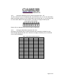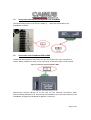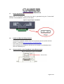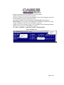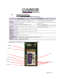
1
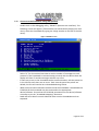
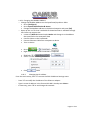
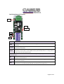
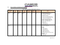
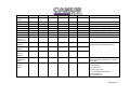
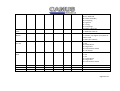
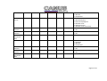
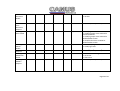
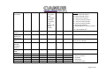
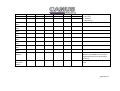
DynaFlame/DynaForce
BMS Protocol
(Modbus, Bacnet IP,
Bacnet MSTP, LONWorks,
Metasys N2) Installation
Guide
93-0238 Rev. 3.2
6226 Netherhart Road, Mississauga, L5T 1B7, 905-696-7800
DynaFlame/DynaForce SOLA and BMS Protocols
Table of Contents
1.1
1.2
1.3
1.5
1.6
1.7
1.8
1.10
1.11
1.12
Bacnet/LONWorks/Metasys N2Setup through Protocessor Protonode RER/LER .............. 3
Protonode RER and LER showing connection ports .......................................................... 3
Record Identification Data ............................................................................................... 3
Connection from DynaFlame/DynaForce to ProtoNode ................................................... 7
Connection from ProtoNode RER to BMS ......................................................................... 7
Power Up the Device ....................................................................................................... 8
Install and Run the Utility Software .................................................................................. 8
Connect to the ProtoNode using RUI (Ruinet) ................................................................ 10
Troubleshooting Tips ..................................................................................................... 12
ProtoNode Specifications............................................................................................... 14
LonWorks Protocol Gateway ............................................................................................. 16
ProtoCarrier 485 (FPC-CD2) .............................................................................................. 17
RS-485 Signal LEDs ............................................................................................................ 17
2.1
Modbus ......................................................................................................................... 17
2.2
Bacnet, Modbus and Metasys N2 Registers.................................................................... 18
2.3
Lockout Codes ............................................................................................................... 30
2.4
PII, LCI, ILK Terminal Configuration ................................................................................ 34
2.5
SOLA Alert Codes ........................................................................................................... 34
Appendix A................................................................................................................................ 45
Page 2 of 51
1.1
Bacnet/LONWorks/Metasys N2Setup through Protocessor Protonode
RER/LER
Installation steps for the customer
1. Record the information about the unit See Section
2. Set the DIP switches
3. Connect up the Field and Host cable
4. Connect the power
1.2
Protonode RER and LER showing connection ports
Figure 1: Protonode Bacnet/ Metasys N2 RER (left) and Lonworks (LER)
1.3
Record Identification Data
Each ProtoNode has a unique part number located on the underside of the unit. The
number format is FPC-N3(4,5)-XXX-XXX-XXXX. This number should be recorded as it may
be required for technical support.
Page 3 of 51
1.4
Configure the DIP Switches
1.4.1
Setting the Protocol that is required on site.
Selecting the required Protocol
To configure the Protonode to match what is on site please follow the below chart
identifying the dipswitch settings for the different configurations. For example, if the
BMS requires communication over Bacnet IP and there are four boilers on site the
technician would select Bacnet IP 4 Sola and configure the S0 – S3 dipswitches on the
ProtoCarrier accordingly.
Power must be cycled after the dip switch settings have been adjusted in order for the
changes to take effect
Page 4 of 51
FPC-N34-103-122-0565 Dipswitch settings
S0
Off
On
Off
On
Off
On
Off
On
Off
On
Off
On
Off
On
Off
On
Off
On
Off
On
Off
On
Off
On
ProtoCarrier
Dipswitches
S1
S2
Off
Off
Off
Off
On Off
On Off
Off
On
Off
On
On On
On On
Off
Off
Off
Off
On Off
On Off
Off
On
Off
On
On On
On On
Off
Off
Off
Off
On Off
On Off
Off
On
Off
On
On On
On On
S3
Off
Off
Off
Off
Off
Off
Off
Off
On
On
On
On
On
On
On
On
Off
Off
Off
Off
Off
Off
Off
Off
A1
A2
ProtoCessor Dipswitches
A3
A4
A5
A6
A7
A8
Refer to 1.4.2 to set the Node/ID device
Instance
On
On
On
On
On
On
On
On
Off
Off
Off
Off
Off
Off
Off
Off
Off
Off
Off
Off
Off
Off
Off
Off
Off
Off
Off
Off
Off
Off
Off
Off
Off
Off
Off
Off
Off
Off
Off
Off
Off
Off
Off
Off
Off
Off
Off
Off
Off
Off
Off
Off
Off
Off
Off
Off
Off
Off
Off
Off
Off
Off
Off
Off
Profile
BACnet IP 1 Sola
BACnet IP 2 Sola
BACnet IP 3 Sola
BACnet IP 4 Sola
BACnet IP 5 Sola
BACnet IP 6 Sola
BACnet IP 7 Sola
BACnet IP 8 Sola
BACnet MSTP 1 Sola
BACnet MSTP 2 Sola
BACnet MSTP 3 Sola
BACnet MSTP 4 Sola
BACnet MSTP 5 Sola
BACnet MSTP 6 Sola
BACnet MSTP 7 Sola
BACnet MSTP 8 Sola
Metasys N2 1 Sola
Metasys N2 2 Sola
Metasys N2 3 Sola
Metasys N2 4 Sola
Metasys N2 5 Sola
Metasys N2 6 Sola
Metasys N2 7 Sola
Metasys N2 8 Sola
FPC-N35-103-401-0566 Dipswitch settings
S0
Off
On
Off
On
Off
On
Off
On
ProtoCarrier Dipswitches
S1
S2
S3
Off
Off
Off
Off
Off
Off
On
Off
Off
On
Off
Off
Off
On
Off
Off
On
Off
On
On
Off
On
On
Off
Profile
Lonworks 1 Sola
Lonworks 2 Sola
Lonworks 3 Sola
Lonworks 4 Sola
Lonworks 5 Sola
Lonworks 6 Sola
Lonworks 7 Sola
Lonworks 8 Sola
Page 5 of 51
1.4.2
Setting the Node/ID Device Instance (Dipswitch A0 – A7)
The DIP switches on the ProtoNode RER and LER allow users to set the Baud Rate,
Node-ID and Mac address on the Field RS-485. Dip switches A0 – A7 can also be used
to set the MAC Address for BACnet MSTP. This does not apply to Metasys N2.
Figure 2: A0 – A7 Dip Switches
Please refer to Appendix A for the full range of addresses.
1.4.3
Setting the Baud Rate (Dipswitch B0 –B3)
Setting the serial baud rate to match the baud rate provided by the BMS can be
done through dipswitches B0 – B3. This does not apply to Metasys N2, as the baud
rate is fixed at 9600 bps.
Table 1: Baud Rate Dip Switch Selection
Baud
110
300
600
1200
2400
4800
9600
19200
20833
28800
38400
57600
76800
115200
B0
B1
B2
B3
Off
Off
On
Off
On
Off
On
Off
On
Off
On
Off
On
Off
Off
On
On
Off
Off
On
On
Off
Off
On
On
Off
Off
On
Off
Off
Off
On
On
On
On
Off
Off
Off
Off
On
On
On
Off
Off
Off
Off
Off
Off
Off
On
On
On
On
On
On
On
Page 6 of 51
1.5
Connection from DynaFlame/DynaForce to ProtoNode
The DynaFlame/DynaForce terminals J3-MB2 (+, -, GND) are connected to the
ProtoNode as shown.
1.6
Connection from ProtoNode RER to BMS
The Bacnet MSTP/ Metasys N2 system can be connected to the 3-pin connector as
shown. When LonWorks is used, a 2-pin connector of the same type is used instead.
Figure 3: Connection from ProtoNode to BMS
Alternatively connect Bacnet IP to the hub via the Ethernet connection when
communicating with Bacnet IP. Ensure that the field device is on the same subnet as the
ProtoNode. Change the ProtoNode IP address if necessary.
Page 7 of 51
1.7
Power Up the Device
Apply power to the device. Ensure that the cable is grounded using the “Frame-GND”
terminal. The ProtoNode is factory set for 24Vac.
Figure 4: Supply Voltage to ProtoNode
1.8
Install and Run the Utility Software
-
1.9
Download the RUINET Utilities from the Protocessor web site (under Utilities
section – Install.zip) www.protocessor.com/downloads/
Run Install.zip and follow the installation instructions
Once installed, the FieldServer Utilities can be located in the Windows Start
menu as a desktop icon
Connect the PC to the ProtoNode via the Ethernet port
Figure 5: Ethernet port location of ProtoNode
Page 8 of 51
-
-
Disable any wireless Ethernet adapters on the PC/Laptop
Disable firewall and virus protection software
Connect an Ethernet cross-over cable between the PC and ProtoNode and the PC
to the Hub/Switch using a straight cat5 cable
The Default IP Address of the ProtoNode is 192.168.1.24, Subnet Mask is
255.255.255.0. If the PC and the ProtoNode are on different IP Networks, assign
a static IP Address to the PC on the 192.168.1.0 network.
Double click on the “RUIPING” Utility. If the IP Address of the ProtoNode module
appears on the screen, the ProtoNode is running.
Go to Start > Programs > Field Server Utilities > Ruiping Utility
Figure 6: RUIPING screen
Page 9 of 51
1.10
-
Connect to the ProtoNode using RUI (Ruinet)
Double click on the debugging utility, “RUINET” (Remote User Interface). The
following screen will appear: (if Ruinet does not automatically display the main
menu, select the ProtoNode by typing the 2-digit number to the left of the title
name).
Figure 7: RUINET screen
-
-
-
-
Select “O” for Connection Overview to see the number of messages on each
protocol. If the ProtoNode is communicating correctly with the device then the
display will show Tx and Rx messages without any errors.
If there are errors on the ProtoNode socket communications, edit the points list
in the CSV file until there are no errors. Each time the points the points are
edited, the CSV will need to be re-downloaded using Ruinet.
When communication between the device and the ProtoNode is established the
Field Side of the ProtoNode may be connected to the appropriate
device/software. Ensure that the Field Side parameters on the device/software
are setup as per the “ProtoNode Mapping” document.
Read and write data from each side and make sure the ProtoNode works as
expected.
Page 10 of 51
1.10.1 Changing the Modbus Address
o Change the Modbus Address on the DynaFlame/DynaForce SOLA
Go to [Configure]
Go to System Identification & Access
Change the Modbus address to the desired setpoint and press [OK]
o Open up the .csv file that is available for download that is available through
the Camus rep support site
Locate cell Node ID located under Nodes and change it to the address
that specified in the Honeywell SOLA
Connect 24Vac to the ProtoNode
Connect Ethernet Cable from computer to device
Turn on device
Go to
>
>
Right-click on Local Area Connection > Properties
Highlight
>
Select: Use the following IP address
Click
twice
1.10.2
Changing the IP address
From the main menu, press “I” to enter the Edit IP Address Settings menu
-
Press “1” to modify the IP address of the Ethernet adapter
Type in a new IP address in the format 192.168.2.X and press <Enter>
If necessary, press “2” to and change the netmask
Page 11 of 51
1.11
Troubleshooting Tips
Connection to the ProtoNode
- Confirm that the network cabling is correct
- Confirm that the computer network card is operational and correctly configured
- Confirm that there is an Ethernet adapter installed in the PC’s Device Manager
List, and that it is configured to run the TCP/IP protocol.
- Check that the IP netmask of the PC matches the ProtoNode. The Default IP
Address of the ProtoNode is 192.168.1.24, Subnet Mask is 255.255.255.0
- Go to Start > Run
- Type in “ipconfig”
- The account settings should be displayed
- Ensure that the IP address is 192.168.1.xxx and the netmask
255.255.255.0
- Ensure that the PC and ProtoNode are on the same IP Network, or assign a Static
IP Address to the PC on the 192.168.1.0 network using the Remote User
Interface Utility.
- If Using Windows XP, ensure that the firewall is disabled
- Ensure that all other Ethernet cards active on the PC, especially wireless
adapters are disabled
- Refer to the FieldServer Troubleshooting Guide which can be found at
www/protocessor.com/downloads/ under documentation
Page 12 of 51
No communication with BMS.
NOTE: If a dipswitch setting is altered, power to the Protonode must be reset
Troubleshooting steps for end-user/integrator
-
Flip BMS/Local switch to BMS
-
Verify A bank dipswitches to set the address of the ProtoNode on the Field Protocol
-
Verify B bank dipswitches to set the baud rate of the ProtoNode on the Field Protocol
o BACnet MSTP only
-
Verify S bank dipswitches to select the profile
-
Verify power connection to ProtoNode
o right 3-pins of 6-pin connector on the ProtoNode
o Check for 24 VAC
-
Verify Modbus connection between ProtoNode and Sola Controller
o left 3-pins of 6-pin connector on the ProtoNode
o Check for 2-3Vdc signal at ‘+’ and ‘-‘ terminals on the Protonode
o Check for 2-3Vdc signal at ‘+’ and ‘-‘ at J3-A (white, 13), J3-(yellow, 14) on the
Sola Controller
-
Verify connection to the field network
o Ethernet connection or 3-pin RS485 connector
o For the ethernet connection, verify the IP address settings of the ProtoNode
-
If there are still issues, use FST diagnostic utility and send capture to Camus support and
send a copy to Field Server to Clarke Ramilo at [email protected]
Page 13 of 51
1.12
ProtoNode Specifications
Table 2: ProtoNode RER/LER Specifications
BacNet MSTP, BacNet IP and Metasys N2 Protocol Gateway
R1 RS485 TX
R1 RS485 RX
RUN
PWR
SYS ERR
COMM ERR
Config ERR
UNUSED
Node Offline
Page 14 of 51
Light
PWR
SYS ERR
COMM
ERR
Config
ERR
Node
Offline
Unused
RX
TX
RUN
Description
This is the power light and should show steady green at all times when the FPC-FD2 is powered.
The SYS ERR LED will go on solid 15 seconds after power up. It will turn off after 5 seconds. A steady
red light will indicate there is a system error on the ProtoCessor. If this occurs, immediately report
the related “system error” shown in the error screen of the RUI interface to FieldServer Technologies
for evaluation.
COMM ERR LED will go on solid 15 seconds after power up. It will turn off after 5 seconds. A steady
red light will indicate the communications problem if there is a configured node connected to the
ProtoCessor that is offline. To establish the cause of the error, go to the error screen of the RUI
interface.
Config ERR LED will go on solid 15 seconds after power up. It will turn off after 5 seconds. A steady
amber light will indicate a configuration error exists in the active configuration. See the Error Screen
in the Remote User Interface for a description of the configuration error.
Node Offline LED will go on solid 15 seconds after power up. It will turn off after 5 seconds. If the
Node Offline LED stays on solid, a node offline condition has occurred.
15 seconds after powering up the 4 unused LEDs will turn on solid for 5 seconds, then turn off.
On normal operation of FPC-FD2, the RX LED will flash when a message is received on the field port
of the ProtoCessor.
On normal operation of FPC-FD2, the TX LED will flash when a message is sent on the field port of
the ProtoCessor
RUN LED will flash 20 seconds after power up, signifying normal operation. The FPC-FD2 will be able
to access RUINET once this LED starts flashing. During the first 20 seconds, the LED should be off
Page 15 of 51
LonWorks Protocol Gateway
LON
PWR
GP105
Rx
Tx
LA
Light
Description
This is the power light and should show steady green at all times when the FFP-F04 is
powered.
Starts flashing about once per second to indicate that the PIC in the ProtoCessor has
LA-PIC A
powered up successfully
Will go on solid within 45 – 60 seconds after power up, signifying normal operation. The
GP105
ProtoCessor will be able to access RUINET shortly after this LED comes on. During the first
45-60 seconds the LED should be dark.
Upon successful operation of GP105 the ProtoCessor will go through diagnostics of the field port
communications.
On normal operation of FFP-F04, the RX LED will flash when a message is received on the
RX
LON port of the ProtoCessor.
On normal operation of FFP-F04,, the TX LED will flash when a message is sent on the LON
TX
port of the ProtoCessor
When the unit is first powered up, before commissioning has occurred, this LED will flash.
LON
Once the unit is commissioned, the LED will stay off during normal operation
PWR
Page 16 of 51
ProtoCarrier 485 (FPC-CD2)
RS-485 Signal LEDs
The RS-485 Signal LEDS are each labeled and correspond to the respective data lines
sent from the ProtoCessor. The following signals are provided. RS-485 TX and RS-485
RX.
2.1
Modbus
The DynaFlame/DynaForce is equipped with a standard ICP Modbus port through a 3-pin
connector that interfaces to the following RS-485 signals:
Table 3: Connection Terminals
Signal
Terminal
Data + (a)
1
Data – (b)
2
Serial transmission mode on the Modbus network is RTU mode. Message format has the
following characteristics:
Table 4: DynaFlame/DynaForce SOLA Data Transmission Specifications
Coding system
8-bit binary
Number of data bits per character 10
1 Start bit
8 data bits, no parity bit
1 stop bit
Bit transfer rate
38400 bps
Duplex
Half Duplex
Error Checking
2 byte CRC-16 polynomial
Bit transfer order
LSB first
End of message
Idle line for 3.5 or more characters
Page 17 of 51
2.2
Bacnet, Modbus and Metasys N2 Registers
Table 5: Modbus and Bacnet IP/MSTP Register Addresses
Parameter
Name
Limits
Demand
Source
Modbus
Address
(hex)
0004
Modbus
Register
(dec)
0004
Bacnet/
N2 Data
Type
AI/AI
Bacnet/ N2
Object ID
LonWorks
Object ID
1
0
R
0006
0006
AI/AI
2
1
R
Read/Write
Note
15-12 Reserved (always 0)
11 = Heat exchanger high limit
10 = Exchanger T-rise limit
9 = Outlet T-rise limit
8 = Inversion inlet/exchanger limit
7 = Inversion exchanger/outlet limit
6 = Inversion inlet/outlet limit
5 = Delta T inlet/exchanger limit
4 = Delta T exchanger/outlet limit
3 = Delta T inlet/outlet limit
2 = Stack limit
1 = DHW high limit
0 = Outlet high limit
0 = Unknown
1 = No source demand
2 = CH
3 = DHW
4 = Lead Lag slave
5 = Lead lag master
6 = CH frost protection
7 = DHW frost protection
8 = No demand due to burner switch
turned off
9 = DHW storage
10 = Reserved
Page 18 of 51
Outlet
Sensor
Firing Rate
Fan Speed
Flame Signal
Inlet Sensor
DHW Sensor
S5 Sensor
Stack Sensor
4-20mA
remote
control input
Active CH
Setpoint
Active DHW
Setpoint
Active Lead
Lag (LL)
Setpoint
Analog
modulation
input
Burner
Control
Status
0007
0007
AI/AI
3
2
R
11 = Warm weather shutdown
-40 – 130oC (0.1oC precision)1
0008
0009
0010
000B
000C
000D
000E
000F
0008
0009
0010
0011
0012
0013
0014
0015
AI/AI
AI/AI
AI/AI
AI/AI
AI/AI
AI/AI
AI/AI
AI/AI
4
5
6
7
8
9
10
11
0
4
5
6
7
8
9
10
R
R
R
R
R
R
R
R
Actual Fire Rate (%2 or RPM3)
RPM
0.01V (0.00 – 50.00V)
-40 – 130oC (0.1oC precision)1
-40 – 130oC (0.1oC precision)1
-40 – 130oC (0.1oC precision)1
-40 – 130oC (0.1oC precision)1
4-20mA (0.1mA precision)
0010
0016
AI/AI
12
11
R
-40 – 130oC (0.1oC precision)1 Setpoint
determined by CH Setpoint source
0011
0017
AI/AI
13
12
R
0012
0018
AI/AI
14
13
R
0015
0021
AI/AI
15
14
R
0020
0032
AI/AI
16
15
R
0 = No signal, otherwise 4-20mA
(0.1mA precision). Duplicate of register
(hex) 0015.
0 = Disabled
1 = Locked Out
2-3 = Reserved
4 = Anti-short cycle
5 = Unconfigured safety data
6-33 = Reserved
34 = Standby hold
Page 19 of 51
Lockout
Code
Alarm
Reason
0022
0034
AI/AI
17
16
R
0023
0035
AI/AI
18
17
R
Annunciator
first out
0024
0036
AI/AI
19
18
R
Annunciator
hold
0025
0037
AI/AI
20
19
R
Hold code
Remote Stat
CH Status
0028
002A
0040
0040
0042
0064
AI/AI
AI/AI
AI/AI
21
22
23
20
21
22
R
R/W
R
35 = Standby delay
36-47 = Reserved
48 = Normal standby
49 = Preparing
50 = Ignition
51 = Firing
52 = Postpurge
53-65535 = Reserved
0 = No lockout
1 – 4096 (See Table 4)
0 = None
1 = Lockout, see register (hex) 0015 for
lockout code
2 = Alert (See Table 6)
0 = None
1 = ILK
12 = Flow Switch
13 = High Limit
14 = Gas Pressure Switch
15 = Air Switch
0 = None
1 = ILK
3 = LCI
12 = Flow Switch
13 = High Limit
14 = Gas Pressure Switch
Reason for burner hold (See Table 4)
Reserved for future use
0 = Unknown
Page 20 of 51
CH Setpoint
Source
0041
0065
AI/AI
24
23
R
CH Heat
Demand
CH Burner
Demand
CH
Requested
Rate
DHW Status
0042
0066
AI/AI
25
24
R
0043
0067
AI/AI
26
25
R
0044
0068
AI/AI
27
26
R
0050
0080
AI/AI
28
27
R
DHW Heat
Demand
DHW Burner
Demand
DHW
Requested
Rate
0053
0083
AI/AI
29
28
R
0054
0084
AI/AI
30
29
R
0055
0085
AI/AI
31
30
R
1 = Disabled
2 = Normal
3 = Suspended
0 = Unknown
1 = Normal Setpoint
2 = Time of Day Setpoint
3 = Outdoor reset
4 = Remote control
7 = Outdoor reset time of day
0 = Off
1 = On
0 =Off
1 = On
RPM or %3
0 = Unknown
1 = Disabled
2 = Normal
3 = Suspended
0 = Off
1 = On
0 = Off
1 = On
RPM or %3
Page 21 of 51
Bitmap
15 – 14 = Reserved
13 = Auxiliary 2 pump demand
12 = Auxiliary 1 pump demand
11 = System pump demand
10 = Boiler pump demand
9 = DHW pump demand
8 = CH pump demand
Reason
7 = Reserved
6 = Pump assigned to logical pump
5 = Pump exercise requested
4 = Pump on due to exercise
3 = Pump on due to Post pump
2 = Forced off
1 = Forced on
0 = On due to normal demand
Application Build < 1600
Application Build > 1600
Pump A
Status
005D
0093
AI/AI
32
31
R
Pump B
Status
005E
0094
AI/AI
33
32
R
CH pump
status
DHW pump
status
System
pump status
Boiler Pump
Status
Burner Cycle
Count
Burner Run
Time
0060
0096
AI/AI
34
33
R
0064
0100
AI/AI
35
34
R
0069
0105
AI/AI
36
35
R
006C
0108
AI/AI
37
36
R
0080-0081
0128-0129
AV/AO
89
R/W
0-999,999
0082-0083
0130-0131
AV/AO
90
R/W
0-999,999 hours
CH Pump
0084-0085
0132-0133
AV/AO
91
R/W
0-999,999
3
Page 22 of 51
Cycle Count
DHW Pump
Cycle Count
System
Pump Cycle
Count
Boiler Pump
Cycle Count
Controller
Run Time
Lead Lag
Master
Status
0086-0087
0134-0135
AV/AO
92
4
R/W
0-999,999
0088-0089
0136-0137
AV/AO
93
5
R/W
0-999,999
008A-008B
0138-0139
AV/AO
94
5
R/W
0-999,999
0090-0091
0144-0145
AI/AI
95
7
R
0-999,999 hours
00A0
0160
AI/AI
38
37
R
Lead Lag
Slave Status
00A1
0161
AI/AI
39
38
R
Pump C
Status
00A8
0168
AI/AI
40
39
R
0 = Unknown
1 = Disabled
2 = Normal
3 = Suspended
Bitmap
15 = Slave command received
14 = Slave mode has priority over CH &
DHW
13 = Slave is modulating
12 = CH frost protection request
11 = DHW frost protection request
10 = Frost protection burner request
9 = Local frost protection request
8 = Reserved (always 0)
7-0 = Burner control status see
register (hex) 32
Bitmap
15 – 14 = Reserved
13 = Auxiliary 2 pump demand
12 = Auxiliary 1 pump demand
Page 23 of 51
40
R
11 = System pump demand
10 = Boiler pump demand
9 = DHW pump demand
8 = CH pump demand
Reason
7 = Reserved
6 = Pump assigned to logical pump
5 = Pump exercise requested
4 = Pump on due to exercise
3 = Pump on due to Post pump
2 = Forced off
1 = Forced on
0 = On due to normal demand
-40 – 130oC (0.1oC precision)1
Outdoor
Temperature
Operating
System (OS)
Number
Date Code
00AA
0170
AI/AI
41
00BA
0186
AI/AI
42
R
Variable length string (up to 16
characters)
00BB
0187
AI/AI
43
R
Variable length string (up to 10
characters)
Safety
processor
build
Application
processor
build
Installer
Password
Burner
Switch
00BC
0188
AI/AI
44
R
00BD
0189
AI/AI
45
R
00BE
0190
AV/AO
46
45
W
Password: sola
00CB
0203
AV/AO
47
46
R/W
Used to enable/disable burner control
0 = Off
Page 24 of 51
R/W
1 = On
0 = Disable Central Heating
1 = Enable Central Heating
-40 – 130oC (0.1oC precision)1
-40 – 130oC (0.1oC precision)1.
Reserved for future use
0 = Disable outdoor reset
1 = Enable outdoor reset
SAFETY PARAMETER
0-64800 seconds (18 hours)
SAFETY PARAMETER
0-64800 seconds (18 hours)
0 = DHW Disabled
1 = DHW Enabled
CH Enable
00D0
0208
AV/AO
48
CH Setpoint
CH Time of
Day Setpoint
CH Outdoor
Reset Enable
Prepurge
Time
Postpurge
Time
DHW
Demand
Switch
DHW
Setpoint
Outlet High
Limit
Setpoint
CH Outdoor
Max Outdoor
Temperature
CH Outdoor
Min Water
Temperature
CH Frost
Protection
Enable
00D3
00D4
0211
0212
AV/AO
AV/AO
49
50
48
49
R/W
R/W
00D7
0215
AV/AO
51
50
R/W
00E7
0231
AV/AO
52
R/W
00EC
0236
AV/AO
53
R/W
01C1
0449
AV/AO
54
53
R/W
01C5
0453
AV/AO
55
54
R/W
-40 – 130oC (0.1oC precision)1
01D0
0464
AV/AO
56
R/W
SAFETY PARAMETER
-40 – 130oC (0.1oC precision)1
0200
0512
AV/AO
58
57
R/W
-40 – 130oC (0.1oC precision)1
0201
0513
AV/AO
59
58
R/W
-40 – 130oC (0.1oC precision)1
0210
0528
AV/AO
60
R/W
0 = Disable
1 = Enable
Page 25 of 51
DHW Frost
Protection
Enable
0211
0529
AV/AO
61
R/W
0 = Disable
1 = Enable
Outdoor
Frost
Protection
Setpoint
Lead Lag
Slave Enable
0212
0530
AV/AO
62
R/W
-40 – 130oC (0.1oC precision)1
0220
0544
AV/AO
63
R/W
Lead Lag
Master
Enable
Lead Lag
Setpoint
Lead Lag
Modulation
Sensor
Lead Lag CH
Modbus
Setpoint
0221
0545
AV/AO
64
R/W
0 = Lead/Lag slave disabled
1 = Lead/lag simple slave enabled for
EnviraCom Master
2 = Lead/lag simple slave enabled for
Global Modbus master
3= Lead/lead full slave enabled for
Global Modbus master
0 = Not a lead/Lag master
1 = Lead/Lag master
0222
0546
AV/AO
65
R/W
-40 – 130oC (0.1oC precision)1
022E
0558
AV/AO
66
R/W
0232
0562
AV/AO
67
Sensor used for Lead Lag modulation:
0 = S5 sensor
1 = S10 sensor
-40 – 130oC (0.1oC precision)1
65
R/W
Page 26 of 51
Slave
Command
0235
0565
AV/AO
98(Boiler
Firing Rate
using
percentage),
99 (Boiler
Firing Rate
using
Binary), 100
(Boiler
Enable)
R/W
CH Modbus
Setpoint
CH
Modulation
Rate Source
CH Modbus
Rate
Warm
Weather
Shutdown
Setpoint
Lead Lag
DHW
Setpoint
Slave 1 State
Slave 2 State
Slave 3 State
Slave 4 State
Slave 5 State
0243
0579
AV/AO
68
R/W
Bitmap
15 = Slave demand request
14 = Slave suspend startup
13 = Slave run fan request
12 = Turn on auxiliary pump X
11 = Turn on auxiliary pump Y
10 = Turn on auxiliary pump Z
9 = Slave pump demand
8 = Commanded rate is binary fraction
%5
7-0 = Commanded rate4
-40 – 130oC (0.1oC precision)1
0244
0580
AV/AP
69
R/W
0 = Local modulation (sensor)
0245
0581
AI/AI
96
R
0274
0628
AV/AO
71
70
R/W
Commanded CH modulation rate4
when source is Modbus
-40 – 130oC (0.1oC precision)1
02C1
0705
AV/AO
72
71
R/W
-40 – 130oC (0.1oC precision)1
0302
0306
030A
030E
0312
0770
0774
0778
0782
0786
AI/AI
AI/AI
AI/AI
AI/AI
AI/AI
73
75
77
79
81
72
74
76
78
80
R
R
R
R
R
Slave State:
0 = Slave is unknown
1 = Available
2 = Add Stage
3 = Suspended Stage
68
Page 27 of 51
Slave 6 State
Slave 7 State
Slave 8 State
0316
031A
031E
0790
0794
0798
AI/AI
AI/AI
AI/AI
83
85
87
82
84
86
R
R
R
Slave 1 Firing
Rate
Slave 2 Firing
Rate
Slave 3 Firing
Rate
Slave 4 Firing
Rate
Slave 5 Firing
Rate
Slave 6 Firing
Rate
Slave 7 Firing
Rate
Slave 8 Firing
Rate
Lead Boiler
Address
0304
0772
AI/AI
74
R
0308
0776
AI/AI
76
R
030C
0780
AI/AI
78
R
0310
0784
AI/AI
80
R
0314
0788
AI/AI
82
R
0318
0792
AI/AI
84
R
031C
0796
AI/AI
86
R
0320
0800
AI/AI
88
R
0321
0801
AI/AI
97
103
R
Lead Lag
Operation
Switch
022B
0555
BV/DO
104
105
R/W
4 = Firing
5 = On leave
6 = Disabled
7 = Recovering
Current firing rate (0-100%)
Modbus address of the first boiler that
will be or was added to service Lead
Lag demand (slave must be available
for firing)
To enable/disable the Lead Lag boiler
plant
Page 28 of 51
All temperature registers are expressed in oC regardless of what temperature units are set to
on the boiler, ex. 32.0oC = 320. A temperature that is NOT applicable has a value of 0x8FFF.
2
All percentage values are given in 0.1% granularity, ie. 0-1000 is the range from 0.0 – 100.0%
3
Most significant bit in value determines which units type the parameter has: 0 = RPM, 1 = %. If
modulation output parameter doesn’t match with the setting of this bit, then the parameter
setting is invalid
4
For binary fraction % format commanded rate is a binary fraction between .00000000 (0% = no
heat at all) and .11111111 (99.98% = maximum fire). For a 0.5% step format commanded rate is
a value between 0 (minimum fire) and 200 (maximum fire) that is a multiple of 0.5% (200 x 0.5%
= 100%)
5
Commanded rate in least significant byte of this register can be expressed in two formats:
binary fraction % or multiple of 035% steps. Bit 8 of this register indicates which format the
commanded rate is expressed in; when bit 8 is set, the commanded rate is in binary fraction %
format when bit 8 is cleared, the commanded rate is in 0.5% steps.
1
Page 29 of 51
2.3
Lockout Codes
Table 6: Lockout Codes
Code
0
Description
None
1
2
3
4
5
6
7
8
9
10
11
12
13
14
15
16
17
18
19
20
21
22
23
24
25
Unconfigured safety data
Waiting for safety data verification
Internal fault: Hardware fault
Internal fault: Safety relay feedback error
Internal fault: Unstable power (DCDC) output
Internal fault: Invalid processor clock
Internal fault: Safety relay drive error
Internal fault: Zero crossing not detected
Internal fault: Flame bias out of range
Internal fault: Invalid burner control state
Internal fault: Invalid burner control state flag
Internal fault: Safety relay drive cap short
Internal fault: PII shorted to ILK
Internal fault: HFS shorted to LCI
Internal fault: Safety relay test failed due to feedback ON
Internal fault: Safety relay test failed due to safety relay OFF
Internal fault: Safety relay test failed due to safety relay not OFF
Internal fault: Safety relay test failed due to feedback not ON
Internal fault: Safety RAM write
Internal fault: Flame ripple and overflow
Internal fault: Flame number of sample mismatch
Internal fault: Flame bias out of range
Internal fault: Bias changed since heating cycle starts
Internal fault: Spark voltage stuck low or high
Internal fault: Spark voltage changed too much during flame
sensing time
Internal fault: Static flame ripple
Internal fault: Flame rod shorted to ground detected
Internal fault: A/D linearity test failed
Internal fault: Flame bias cannot be set in range
Internal fault: Flame bias shorted to adjacent pin
Internal fault: SLO electronics unknown error
Internal fault: Safety key 0
Internal fault: Safety key 1
Internal fault: Safety key 2
Internal fault: Safety key 3
Internal fault: Safety key 4
Internal fault: Safety key 5
26
27
28
29
30
31
32
33
34
35
36
37
Note
No
lockout/hold
Lockout
Lockout
Hold
Hold
Hold
Hold
Hold
Hold
Hold
Lockout
Lockout
Hold
Hold/Lockout
Hold/Lockout
Lockout
Lockout
Lockout
Lockout
Lockout
Hold
Hold
Hold
Hold
Hold
Hold
Hold
Hold
Hold
Hold
Hold
Hold
Lockout
Lockout
Lockout
Lockout
Lockout
Lockout
Page 30 of 51
38
39
40
41
42
43
44
45
46
47
48
49
50
51
52
53
54
55
56-57
58
59
60
61
62
63
67
68
69
70
71-77
78
79
81
82
91
92
93
94
95
96
97
98
99
101-104
Internal fault: Safety key 6
Internal fault: Safety key 7
Internal fault: Safety key 8
Internal fault: Safety key 9
Internal fault: Safety key 10
Internal fault: Safety key 11
Internal fault: Safety key 12
Internal fault: Safety key 13
Internal fault: Safety key 14
Flame rod to ground leakage
Static flame (not flickering)
24Vac voltage low/high
Modulation fault
Pump fault
Motor tachometer fault
AC inputs phase reversed
Safety GVT model ID doesn’t match application’s model ID
Application configuration data block CRC errors
RESERVED
Internal fault: HFS shorted to IAS
Internal fault: Mux pin shorted
Internal fault: HFS shorted to LFS
Anti-short cycle
Fan speed not proved
LCI off
ILK off
ILK on
Pilot test hold
Wait for leakage test completion
RESERVED
Demand lost in run
Outlet high limit
Delta T inlet/outlet limit
Stack limit
Inlet sensor fault
Outlet sensor fault
DHW sensor fault
S2 (J8-6) sensor fault
Stack sensor fault
S5 (J8-11) sensor fault
Internal fault: A2D mismatch
Internal fault: Exceeded VSNSR voltage tolerance
Internal fault: Exceeded 28V voltage tolerance
RESERVED
Lockout
Lockout
Lockout
Lockout
Lockout
Lockout
Lockout
Lockout
Lockout
Hold
Hold
Hold
Hold
Hold
Hold
Lockout
Lockout
Lockout
Lockout
Lockout
Lockout
Hold
Hold
Hold
Hold
Hold
Hold
Hold
Hold
Hold
Hold
Lockout
Hold
Hold
Hold
Hold
Hold
Hold
Lockout
Lockout
Lockout
Page 31 of 51
105
106
107
108
109
110
111
112
113
114-121
122
123
124
125
126
127
128
129
130
131
132
133-135
136
137
138-142
143
144
145
146
147
148
149
150
151
158
159
160
161
162
163
166-171
172
173
174
Flame detected out of sequence
Flame lost in MFEP
Flame lost early in run
Flame lost in run
Ignition failed
Ignition failure occurred
Flame current lower than WEAK threshold
Pilot test flame timeout
Flame circuit timeout
RESERVED
Lightoff rate proving failed
Purge rate proving failed
High fire switch OFF
High fire switch stuck ON
Low fire switch OFF
Low fire switch stuck ON
Fan speed failed during prepurge
Fan speed failed during preignition
Fan speed failed during ignition
Fan movement detected during standby
Fan speed failed during run
RESERVED
Interrupted Airflow Switch failed to close
ILK failed to close
RESERVED
Internal fault: Flame bias out of range 1
Internal fault: Flame bias out of range 2
Internal fault: Flame bias out of range 3
Internal fault: Flame bias out of range 4
Internal fault: Flame bias out of range 5
Internal fault: Flame bias out of range 6
Flame detected
Flame not detected
High fire switch ON
Main valve ON
Main valve OFF
Ignition ON
Ignition OFF
Pilot valve ON
Pilot valve OFF
RESERVED
Main relay feedback incorrect
Pilot relay feedback incorrect
Safety relay feedback incorrect
Lockout
Lockout
Lockout
Lockout
Lockout
Hold
Hold
Lockout
Lockout
Lockout
Lockout
Hold
Hold
Hold
Hold
Hold
Hold
Hold
Hold
Hold
Hold
Hold
Lockout
Lockout
Lockout
Lockout
Lockout
Lockout
Lockout
Hold
Hold
Lockout
Lockout
Lockout
Lockout
Lockout
Lockout
Lockout
Lockout
Lockout
Page 32 of 51
175
176
177
178
179-183
184
185
186
187
188
189
192
193
194
195
196
197
198
199
200
201
202
203
204
205
206
207
208
209
210
211
212
213
214
215
216
217
218
219
224
225
226
228
229
Safety relay open
Main relay ON and safe start check
Pilot relay ON at safe start check
Safety relay ON at safe start check
RESERVED
Invalid Blower/HIS output setting
Invalid Delta T limit enable setting
Invalid Delta T limit response setting
Invalid DHW high limit enable setting
Invalid DHW high limit response setting
Invalid Flame sensor type setting
Invalid igniter on during setting
Invalid ignite failure delay setting
Invalid ignite failure response setting
Invalid ignite failure retries setting
Invalid ignition source setting
Invalid interlock open response setting
Invalid Interlock start check setting
Invalid LCI enable setting
Invalid lightoff rate setting
Invalid lightoff rate proving setting
Invalid Main Flame Establishing Period setting
Invalid MFEP flame failure response setting
Invalid NTC sensor type setting
Invalid Outlet high limit response setting
Invalid Pilot Flame Establishing Period setting
Invalid PII enable setting
Invalid pilot test hold setting
Invalid pilot type setting
Invalid postpurge time setting
Invalid power up with lockout setting
Invalid preignition time setting
Invalid prepurge rate setting
Invalid prepurge time setting
Invalid purge rate proving setting
Invalid run flame failure response setting
Invalid run stabilization time setting
Invalid stack limit enable setting
Invalid stack limit enable setting
Invalid DHW demand source setting
Invalid flame threshold setting
Invalid outlet high limit setpoint setting
Invalid Stack limit setpoint setting
Invalid modulation output setting
Lockout
Lockout
Lockout
Lockout
Lockout
Lockout
Lockout
Lockout
Lockout
Lockout
Lockout
Lockout
Lockout
Lockout
Lockout
Lockout
Lockout
Lockout
Lockout
Lockout
Lockout
Lockout
Lockout
Lockout
Lockout
Lockout
Lockout
Lockout
Lockout
Lockout
Lockout
Lockout
Lockout
Lockout
Lockout
Lockout
Lockout
Lockout
Lockout
Lockout
Lockout
Lockout
Lockout
Page 33 of 51
230
231
234
235
236
237
238
239
240
244
246
250
252-255
2.4
Invalid CH demand source setting
Invalid Delta T limit delay setting
Invalid outlet high limit enable setting
Invalid outlet connector type setting
Invalid inlet connector type setting
Invalid DHW connector type setting
Invalid Stack connector type setting
Invalid S2 (J8-6) connector type setting
Invalid S5 (J8-11) connector type setting
Internal fault: Safety relay test invalid state
4-20mA cannot be used for both modulation and setpoint control
Invalid fan speed error message
RESERVED
Lockout
Lockout
Lockout
Lockout
Lockout
Lockout
Lockout
Lockout
Lockout
Lockout
Lockout
Lockout
PII, LCI, ILK Terminal Configuration
Table 7: PII, LCI, ILK Terminal Configuration
Byte Offset
0-2
3
4-23
2.5
Parameter
Interlock short name
Unused
Interlock name
Read/Write
R/W
-R/W
Format
U8
U8
U8
SOLA Alert Codes
Table 8: SOLA Alert Codes
Code
0
1
2
3
4
5
6
7
8
9
10
11
12
13
14
15
16
17
18
19
20
Description
None (No alert)
Alert PCB was restored from factory defaults
Safety configuration parameters were restored from factory defaults
Configuration parameters were restored from factory defaults
Invalid Factory Invisibility PCB was detected
Invalid Factory Range PCB was detected
Invalid range PCB record has been dropped
EEPROM lockout history was initialized
Switched application annunciation data blocks
Switched application configuration data blocks
Configuration was restored from factory defaults
Backup configuration settings was restored from active configuration
Annunciation configuration was restored from factory defaults
Annunciation configuration was restored from backup
Safety group verification table was restored from factory defaults
Safety group verification table was updated
Invalid Parameter PCB was detected
Invalid Range PCB was detected
Alarm silence time exceeded maximum
Invalid safety group verification table was detected
Backdoor password could not be determined
Page 34 of 51
21
22
23
24
25
26
27
28
29
30
31
32
33
34
35
36
37
38
39
40
41
42
43
44
45
46
47
48
49
50
51
52
53
54
55
56
57
58
59
60
61
62
63
64
65
66
67
68
69
Invalid safety group verification table was not accepted
CRC errors were found in application configuration data blocks
Backup Alert PCB was restored from active one
RESERVED
Lead Lag operation switch was turned OFF
Lead Lag operation switch was turned ON
Safety processor was reset
Application processor was reset
Burner switch was turned OFF
Burner switch was turned ON
Program Module (PM) was inserted into socket
Program Module (PM) was removed from socket
Alert PCB was configured
Parameter PCB was configured
Range PCB was configured
Program Module (PM) incompatible with product was inserted into socket
Program Module application parameter revision differs from application
processor
Program Module safety parameter revision differs from safety processor
PCB incompatible with product contained in Program Module
Parameter PCB in Program Module is too large for product
Range PCB in Program Module was too large for product
Alert PCB in Program Module was too large for product
IAS start check was forced on due to IAS enabled
Low voltage was detected in safety processor
High line frequency occurred
Low line frequency occurred
Invalid subsystem reset request occurred
Write large enumerated Modbus register value was not allowed
Maximum cycle count was reached
Maximum hours count was reached
Illegal Modbus write was attempted
Modbus write attempt was rejected (NOT ALLOWED)
Illegal Modbus read was attempted
Safety processor brown-out reset occurred
Application processor watchdog reset occurred
Application processor brown-out reset occurred
Safety processor watchdog reset occurred
Alarm was reset by the user at the control
Burner control firing rate was > absolute max rate
Burner control firing rate was < absolute min rate
Burner control firing rate was invalid, % vs. RPM
Burner control was firing with no fan request
Burner control rate (nonfiring) was > absolute max rate
Burner control rate (nonfiring) was < absolute min rate
Burner control rate (nonfiring) was absent
Burner control rate (nonfiring) was invalid, % vs. RPM
Fan off cycle rate was invalid, % vs. RPM
Setpoint was overridden due to sensor fault
Modulation was overridden due to sensor fault
Page 35 of 51
70
71
7273
74
75
76
77
78
79
80
81
8283
84
85
86
87
88
89
90
91
92
93
94
95
96
97
98
99
100
101
102
103
104
105
106
107
108
109
110
111
112
113
114
115
116
117
118
119
120
121
No demand source was set due to demand priority conflicts
CH 4-20mA signal was invalid
RESERVED
Periodic Forced Recycle
Absolute max fan speed was out of range
Absolute min fan speed was out of range
Fan gain down was invalid
Fan gain up was invalid
Fan minimum duty cycle was invalid
Fan pulses per revolution was invalid
Fan PWM frequency was invalid
RESERVED
Lead Lag CH 4-20mA water temperature setting was invalid
No Lead Lag add stage error threshold was configured
No Lead Lag add stage detection time was configured
No Lead Lag drop stage error threshold was configured
No Lead Lag drop stage detection time was configured
Lead Lag all boiler off threshold was invalid
Modulation output type was invalid
Firing rate control parameter was invalid
Forced rate was out of range vs. min/max modulation
Forced rate was invalid, % vs. RPM
Slow start ramp value was invalid
Slow start degrees value was invalid
Slow start was ended due to outlet sensor fault
Slow start was end due to reference setpoint fault
CH max modulation rate was invalid, % vs. RPM
CH max modulation rate was > absolute max rate
CH modulation range (max minus min) was too small (< 4% or 40 RPM)
DHW max modulation rate was invalid, % vs. RPM
DHW max modulation rate was > absolute max rate
DHW modulation range (max minus min) was too small (< 4% or 40 RPM)
Min modulation rate was < absolute min rate
Min modulation rate was invalid, % vs. RPM
Manual rate was invalid, % vs. RPM
Slow start enabled, but forced rate was invalid
Analog output hysteresis was invalid
Analog modulation output type was invalid
IAS open rate differential was invalid
IAS open step rate was invalid
Mix max modulation rate was invalid, % vs. RPM
Mix max modulation rate was > absolute max or < absolute min rates
Mix modulation range (max minus min) was too small (< 4% or 40 RPM)
Fan was limited to its minimum duty cycle
Manual rate was > CH max modulation rate
Manual rate was > DHW max modulation rate
Manual rate was < min modulation rate
Manual rate in Standby was > absolute max rate
Modulation commanded rate was > CH max modulation rate
Modulation commanded rate was > DHW max modulation rate
Page 36 of 51
122
123
124
125
126
127
128
129
130
131
132
133
134
135
136
137
138
139
140
141
142
143
144
145
146
147
148
149
150
151
152
153
154
155
156
157
158
159
160
161
162
163
164
165
166
167
168
169
170
171
Modulation commanded rate was < min modulation rate
Modulation rate was limited due to Outlet limit
Modulation rate was limited due to Delta-T limit
Modulation rate was limited due to Stack limit
Modulation rate was limited due to anticondensation
Fan speed out of range in RUN
Modulation rate was limited due to IAS was open
Slow start ramp setting of zero will result in no modulation rate change
No forced rate was configured for slow start ramp
CH demand source was invalid
CH P-gain was invalid
CH I-gain was invalid
CH D-gain was invalid
CH OFF hysteresis was invalid
CH ON hysteresis was invalid
CH sensor type was invalid
CH hysteresis step time was invalid
CH remote control parameter was invalid
CH ODR not allowed with remote control
Steam P-gain was invalid
Steam I-gain was invalid
Steam D-gain was invalid
Steam OFF hysteresis was invalid
Steam ON hysteresis was invalid
CH control was suspended due to fault
CH header temperature was invalid
CH Outlet temperature was invalid
CH steam pressure was invalid
Steam setpoint source parameter was invalid
Minimum water temperature parameter was greater than setpoint
Minimum water temperature parameter was greater than time of day setpoint
Minimum pressure parameter was greater than setpoint
Minimum pressure parameter was greater than time of day setpoint
CH modulation rate source parameter was invalid
Steam modulation rate source parameter was invalid
DHW demand source was invalid
DHW P-gain was invalid
DHW I-gain was invalid
DHW D-gain was invalid
DHW OFF hysteresis was invalid
DHW ON hysteresis was invalid
DHW hysteresis step time was invalid
DHW sensor type was invalid
Inlet sensor type was invalid for DHW
Outlet sensor type was invalid for DHW
DHW storage OFF hysteresis was invalid
DHW storage ON hysteresis was invalid
DHW modulation sensor type was invalid
DHW modulation sensor was not compatible for Auto mode
DHW control was suspended due to fault
Page 37 of 51
172
173
174
175
176
177
178
179
180
181
182
183
184
185
186
187
188
189
190
191
192
193
194
195
196
197
198
199
200
201
202
203
204
205
206
207
208
209
210
211
212
213
214
215
216
217
218
219
220
221
DHW temperature was invalid
DHW inlet temperature was invalid
DHW outlet temperature was invalid
DHW high limit must be disabled for Auto mode
DHW sensor type was not compatible for Auto mode
DHW priority source setting was invalid
DHW priority method setting was invalid
CH S5 (J8-11) sensor was invalid
CH Inlet temperature was invalid
CH S10 (J10-7) sensor was invalid
Lead Lag CH setpoint source was invalid
Lead Lag P-gain was invalid
Lead Lag I-gain was invalid
Lead Lag D-gain was invalid
Lead Lag OFF hysteresis was invalid
Lead Lag ON hysteresis was invalid
Lead Lag slave enable was invalid
Lead Lag hysteresis step time was invalid
No Lead Lag Modbus port was assigned
Lead Lag base load common setting was invalid
Lead Lag DHW demand switch setting was invalid
Lead Lag Mix demand switch setting was invalid
Lead Lag modulation sensor setting was invalid
Lead Lag backup modulation sensor setting was invalid
Lead Lag slave mode setting was invalid
Lead Lag rate allocation setting was invalid
Lead selection setting was invalid
Lag selection setting was invalid
Lead Lag slave return setting was invalid
Lead Lag add stage method setting was invalid
STAT may not be a Lead Lag CH demand source when Remote Stat is enabled
Lead Lag base load rate setting was invalid
Lead Lag master was suspended due to fault
Lead Lag slave was suspended due to fault
Lead Lag header temperature was invalid
Lead Lag was suspended due to no enabled Program Module installed
Lead Lag slave session has timed out
Too many Lead Lag slaves were detected
Lead Lag slave was discovered
Incompatible Lead Lag slave was discovered
No base load rate was set for Lead Lag slave
Lead Lag slave unable to fire before demand to fire delay expired
Adding Lead Lag slave aborted due to add requirement change
No Lead Lag slaves available to service demand
No Lead Lag active service was set due to demand priority conflicts
No Lead Lag add stage method was specified
No Lead Lag drop stage method was specified
Using backup Lead Lag header sensor due to sensor failure
Lead Lag frost protection rate was invalid
Lead Lag drop stage method setting was invalid
Page 38 of 51
222
223
224
225-226
227
228
229
230
231
232
233
234
235
236
237
238
239
240
241
242
243
244
245
246
247
248
249
250
251
252
253
254
255
256
257
258
259
260
261
262
263
264
265-266
267
268
269
270
271
272
273
CH frost protection temperature was invalid
CH frost protection inlet temperature was invalid
DHW frost protection temperature was invalid
RESERVED
DHW priority override time was not derated due to invalid outdoor temperature
Warm weather shutdown was not checked due to invalid outdoor temperature
Lead Lag slave communication timeout
RESERVED
Lead Lag CH setpoint was invalid
Lead Lag CH time of day setpoint was invalid
Lead Lag outdoor temperature was invalid
Lead Lag ODR time of day setpoint was invalid
Lead Lag ODR time of day setpoint exceeded normal setpoint
Lead Lag ODR max outdoor temperature was invalid
Lead Lag ODR min outdoor temperature was invalid
Lead Lag ODR low water temperature was invalid
Lead Lag ODR outdoor temperature range was too small (minimum 12 C / 22
F) Lag ODR water temperature range was too small (minimum 12 C / 22 F)
Lead
Lead Lag DHW setpoint was invalid
Lead Lag Mix setpoint was invalid
Lead Lag CH demand switch was invalid
Lead Lag ODR min water temperature was invalid
RESERVED
CH setpoint was invalid
CH time of day setpoint was invalid
CH outdoor temperature was invalid
CH ODR time of day setpoint was invalid
CH ODR time of day setpoint exceeds normal setpoint
CH max outdoor setpoint was invalid
CH min outdoor setpoint was invalid
CH ODR low water temperature was invalid
CH ODR outdoor temperature range was too small
CH ODR water temperature range was too small
Steam setpoint was invalid
Steam time of day setpoint was invalid
Steam minimum pressure was invalid
CH ODR min water temperature was invalid
RESERVED
DHW setpoint was invalid
DHW time of day setpoint was invalid
DHW storage setpoint was invalid
STAT may not be a DHW demand source when Remote Stat is enabled
RESERVED
STAT may not be a CH demand source when Remote Stat is enabled
CH 4mA water temperature setting was invalid
CH 20mA water temperature setting was invalid
Steam 4mA water temperature setting was invalid
Steam 20mA water temperature setting was invalid
Abnormal Recycle: Pressure sensor fault
Abnormal Recycle: Safety relay drive test failed
Page 39 of 51
274
275
276
277
278
279
280
281
282
283
284
285
286
287
288
289
290
291
292
293
294
295
296
297
298
299
300
301
302
303
304
305
306
307
308
309
310
311
312
313
314
315
316
317
318
319
320
321
322
323
Abnormal Recycle: Demand off during Pilot Flame Establishing Period
Abnormal Recycle: LCI off during Drive to Purge Rate
Abnormal Recycle: LCI off during Measured Purge Time
Abnormal Recycle: LCI off during Drive to Lightoff Rate
Abnormal Recycle: LCI off during Pre-Ignition test
Abnormal Recycle: LCI off during Pre-Ignition time
Abnormal Recycle: LCI off during Main Flame Establishing Period
Abnormal Recycle: LCI off during Ignition period
Abnormal Recycle: Demand off during Drive to Purge Rate
Abnormal Recycle: Demand off during Measured Purge Time
Abnormal Recycle: Demand off during Drive to Lightoff Rate
Abnormal Recycle: Demand off during Pre-Ignition test
Abnormal Recycle: Demand off during Pre-Ignition time
Abnormal Recycle: Flame was on during Safe Start check
Abnormal Recycle: Flame was on during Drive to Purge Rate
Abnormal Recycle: Flame was on during Measured Purge Time
Abnormal Recycle: Flame was on during Drive to Lightoff Rate
Abnormal Recycle: Flame was not on at end of Ignition period
Abnormal Recycle: Flame was lost during Main Flame Establishing Period
Abnormal Recycle: Flame was lost early in Run
Abnormal Recycle: Flame was lost during Run
Abnormal Recycle: Leakage test failed
Abnormal Recycle: Interrupted air flow switch was off during Drive to Purge
Rate
Abnormal
Recycle: Interrupted air flow switch was off during Measured Purge
Time
Abnormal
Recycle: Interrupted air flow switch was off during Drive to Lightoff
Rate
Abnormal
Recycle: Interrupted air flow switch was off during Pre-Ignition test
Abnormal Recycle: Interrupted air flow switch was off during Pre-Ignition time
Abnormal Recycle: Interrupted air flow switch was off during Main Flame
Establishing
Period Ignition failed due to interrupted air flow switch was off
Abnormal
Recycle:
Abnormal Recycle: ILK off during Drive to Purge Rate
Abnormal Recycle: ILK off during Measured Purge Time
Abnormal Recycle: ILK off during Drive to Lightoff Rate
Abnormal Recycle: ILK off during Pre-Ignition test
Abnormal Recycle: ILK off during Pre-Ignition time
Abnormal Recycle: ILK off during Main Flame Establishing Period
Abnormal Recycle: ILK off during Ignition period
Run was terminated due to ILK was off
Run was terminated due to interrupted air flow switch was off
Stuck reset switch
Run was terminated due to fan failure
Abnormal Recycle: Fan failed during Drive to Purge Rate
Abnormal Recycle: Fan failed during Measured Purge Time
Abnormal Recycle: Fan failed during Drive to Lightoff Rate
Abnormal Recycle: Fan failed during Pre-Ignition test
Abnormal Recycle: Fan failed during Pre-Ignition time
Abnormal Recycle: Fan failed during Ignition period
Abnormal Recycle: Fan failed during Main Flame Establishing Period
Abnormal Recycle: Main Valve off after 10 seconds of RUN
Abnormal Recycle: Pilot Valve off after 10 seconds of RUN
Abnormal Recycle: Safety Relay off after 10 seconds of RUN
Page 40 of 51
324
325
326
327
328
329
330
331
332
333
334
335
336
337
338
339
340
341
342
343
344
345
346
347
348
349
350
351
352
353
354
355
356
357
358
359
360
361
362
363
364
365
366
367
368
369
370
371
372
373
Abnormal Recycle: Hardware flame bias
Abnormal Recycle: Hardware static flame
Abnormal Recycle: Hardware flame current invalid
Abnormal Recycle: Hardware flame rod short
Abnormal Recycle: Hardware invalid power
Abnormal Recycle: Hardware invalid AC line
Abnormal Recycle: Hardware SLO flame ripple
Abnormal Recycle: Hardware SLO flame sample
Abnormal Recycle: Hardware SLO flame bias range
Abnormal Recycle: Hardware SLO flame bias heat
Abnormal Recycle: Hardware SLO spark stuck
Abnormal Recycle: Hardware SLO spark changed
Abnormal Recycle: Hardware SLO static flame
Abnormal Recycle: Hardware SLO rod shorted
Abnormal Recycle: Hardware SLO AD linearity
Abnormal Recycle: Hardware SLO bias not set
Abnormal Recycle: Hardware SLO bias shorted
Abnormal Recycle: Hardware SLO electronics
Abnormal Recycle: Hardware processor clock
Abnormal Recycle: Hardware AC phase
Abnormal Recycle: Hardware A2D mismatch
Abnormal Recycle: Hardware VSNSR A2D
Abnormal Recycle: Hardware 28V A2D
Abnormal Recycle: Hardware HFS IAS shorted
Abnormal Recycle: Hardware PII INTLK shorted
Abnormal Recycle: Hardware HFS LCI shorted
Abnormal Recycle: Hardware HFS LFS shorted
Abnormal Recycle: Invalid zero crossing
Abnormal Recycle: fault stack sensor
Abnormal Recycle: stack limit
Abnormal Recycle: delta T limit
Abnormal Recycle: fault outlet sensor
Abnormal Recycle: outlet high limit
Abnormal Recycle: fault DHW sensor
Abnormal Recycle: DHW high limit
Abnormal Recycle: fault inlet sensor
Abnormal Recycle: Check Parameters Failed
Internal error: No factory parameters were detected in control
Internal error: PID iteration frequency was invalid
Internal error: Demand-Rate interval time was invalid
Internal error: Factory calibration parameter for modulation was invalid
Internal error: CH PID P-scaler was invalid
Internal error: CH PID I-scaler was invalid
Internal error: CH PID D-scaler was invalid
Internal error: DHW PID P-scaler was invalid
Internal error: DHW PID I-scaler was invalid
Internal error: DHW PID D-scaler was invalid
Internal error: Lead Lag master PID P-scaler was invalid
Internal error: Lead Lag master PID I-scaler was invalid
Internal error: Lead Lag master PID D-scaler was invalid
Page 41 of 51
374
375
376
377
378
379
380
381
382
383-450
451
452
453
454
455
456
457
458
459
460
461
462
463
464
465
466
467
468
469
470
471
472
473
474
475
476
477
478
479
480
481
482
483
484
485
486
487
488
489
490
Abnormal Recycle: Hardware flame bias high
Abnormal Recycle: Hardware flame bias low
Abnormal Recycle: Hardware flame bias delta high
Abnormal Recycle: Hardware flame bias delta low
Abnormal Recycle: Hardware flame bias dynamic high
Abnormal Recycle: Hardware flame bias dynamic low
Abnormal Recycle: Fan Speed Not Proven
Abnormal Recycle: Fan Speed Range Low
Abnormal Recycle: Fan Speed Range High
RESERVED
Circulator control was invalid
Circulator P-gain was invalid
Circulator I-gain was invalid
Circulator temperature was invalid
Circulator outlet temperature was invalid
Circulator inlet temperature was invalid
Circulator outdoor temperature was invalid
Circulator sensor choice was invalid
Circulator PID setpoint was invalid
LCI lost in run
Abnormal Recycle: Demand lost in run from application
Abnormal Recycle: Demand lost in run due to high limit
Abnormal Recycle: Demand lost in run due to no flame
LCI lost in Combustion Pressure Establishing Period
LCI lost in Combustion Pressure Stabilization Period
RESERVED
Internal error: EEPROM write was attempted before EEPROM was initialized
Internal error: EEPROM cycle count address was invalid
Internal error: EEPROM days count address was invalid
Internal error: EEPROM hours count address was invalid
Internal error: Lockout record EEPROM index was invalid
Internal error: Request to write PM status was invalid
Internal error: PM parameter address was invalid
Internal error: PM safety parameter address was invalid
Internal error: Invalid record in lockout history was removed
Internal error: EEPROM write buffer was full
Internal error: Data too large was not written to EEPROM
Internal error: Safety key bit 0 was incorrect
Internal error: Safety key bit 1 was incorrect
Internal error: Safety key bit 2 was incorrect
Internal error: Safety key bit 3 was incorrect
Internal error: Safety key bit 4 was incorrect
Internal error: Safety key bit 5 was incorrect
Internal error: Safety key bit 6 was incorrect
Internal error: Safety key bit 7 was incorrect
Internal error: Safety key bit 8 was incorrect
Internal error: Safety key bit 9 was incorrect
Internal error: Safety key bit 10 was incorrect
Internal error: Safety key bit 11 was incorrect
Internal error: Safety key bit 12 was incorrect
Page 42 of 51
491
492
493
494
495
496
497
498
499
500
501
502
503
504
505
506
507
508
509
510
511
512
513
514
515
516
517
518
519
520
521
522
523
524
525
526
527
528
529
530
531
532
533-539
540
541
542
543
545
546
547
Internal error: Safety key bit 13 was incorrect
Internal error: Safety key bit 14 was incorrect
Internal error: Safety key bit 15 was incorrect
Internal error: Safety relay timeout
Internal error: Safety relay commanded off
Internal error: Unknown safety error occurred
Internal error: Safety timer was corrupt
Internal error: Safety timer was expired
Internal error: Safety timings
Internal error: Safety shutdown
RESERVED
Mix setpoint was invalid
Mix time of day setpoint was invalid
Mix outdoor temperature was invalid
Mix ODR time of day setpoint was invalid
Mix ODR time of day setpoint exceeds normal setpoint
Mix ODR max outdoor temperature was invalid
Mix ODR min outdoor temperature was invalid
Mix ODR low water temperature was invalid
Mix ODR outdoor temperature range was invalid
Mix ODR water temperature range was invalid
Mix demand switch was invalid
Mix ON hysteresis was invalid
Mix OFF hysteresis was invalid
Mix ODR min water temperature was invalid
Mix hysteresis step time was invalid
Mix P-gain was invalid
Mix I-gain was invalid
Mix D-gain was invalid
Mix control was suspended due to fault
Mix S10 (J10-7) temperature was invalid
Mix outlet temperature was invalid
Mix inlet temperature was invalid
Mix S5 (J8-11) temperature was invalid
Mix modulation sensor type was invalid
Mix ODR min water temperature setpoint was invalid
Mix circulator sensor was invalid
Mix flow control was invalid
Mix temperature was invalid
Mix sensor was invalid
Mix PID setpoint was invalid
STAT may not be a Mix demand source when Remote Stat is enabled
RESERVED
Delta T inlet/outlet enable was invalid
Delta T exchanger/outlet enable was invalid
Delta T inlet/exchanger enable was invalid
Delta T inlet/outlet degrees was out of range
Delta T inlet/exchanger degrees was out of range
Delta T response was invalid
Delta T inversion limit response was invalid
Page 43 of 51
548
549
550
551
552
553
554
555
556
557
558
559
560
561
562
563
564
565
566
567
568
569
570
571
572
573
574
575
576
577
578
579
580
581
582-589
590
591
592
593
594
595
596
597
598
599
600
601
602
603
604
Delta T rate limit enable was invalid
Delta T exchanger/outlet wasn't allowed due to stack limit setting
Delta T inlet/outlet limit was exceeded
Delta T exchanger/outlet limit was exceeded
Delta T inlet/exchanger limit was exceeded
Inlet/outlet inversion occurred
Exchanger/outlet inversion occurred
Inlet/exchanger inversion occurred
Delta T exchanger/outlet wasn't allowed due to stack connector setting
Delta T inlet/exchanger wasn't allowed due to stack limit setting
Delta T inlet/exchanger wasn't allowed due to stack connector setting
Delta T delay was not configured for recycle response
Outlet T-rise enable was invalid
Heat exchanger T-rise enable was invalid
T-rise degrees was out of range
T-rise response was invalid
Outlet T-rise limit was exceeded
Heat exchanger T-rise limit was exceeded
Heat exchanger T-rise wasn't allowed due to stack limit setting
Heat exchanger T-rise wasn't allowed due to stack connector setting
Outlet T-rise wasn't allowed due to outlet connector setting
T-rise delay was not configured for recycle response
Heat exchanger high limit setpoint was out of range
Heat exchanger high limit response was invalid
Heat exchanger high limit was exceeded
Heat exchanger high limit wasn't allowed due to stack limit setting
Heat exchanger high limit wasn't allowed due to stack connector setting
Heat exchanger high limit delay was not configured for recycle response
CH pump output was invalid
DHW pump output was invalid
Boiler pump output was invalid
Auxiliary pump output was invalid
System pump output was invalid
Mix pump output was invalid
RESERVED
DHW plate preheat setpoint was invalid
DHW plate preheat ON hysteresis was invalid
DHW plate preheat OFF hysteresis was invalid
Tap detect degrees was out of range
Tap detect ON hysteresis was invalid
Inlet - DHW tap stop degrees was out of range
Outlet - Inlet tap stop degrees was out of range
DHW tap detect on threshold was invalid
DHW plate preheat detect on threshold was invalid
DHW plate preheat detect off threshold was invalid
Delta T inlet temperature was invalid
Delta T outlet temperature was invalid
Delta T exchanger temperature was invalid
Parameter PCB was switched to backup
Range PCB was switched to backup
Page 44 of 51
Appendix A
A7
A6
A5
A4
A3
A2
A1
A0
Address
Off
Off
Off
Off
Off
Off
Off
Off
Off
Off
Off
Off
Off
Off
Off
Off
Off
Off
Off
Off
Off
Off
Off
Off
Off
Off
Off
Off
Off
Off
Off
Off
Off
Off
Off
Off
Off
Off
Off
Off
Off
Off
Off
Off
Off
Off
Off
Off
Off
Off
Off
Off
Off
Off
Off
Off
Off
Off
Off
Off
Off
Off
Off
Off
Off
Off
Off
Off
Off
Off
Off
Off
Off
Off
Off
Off
Off
Off
Off
Off
Off
Off
Off
Off
Off
Off
Off
Off
Off
Off
Off
Off
Off
Off
Off
Off
Off
Off
Off
Off
Off
Off
Off
Off
Off
Off
Off
Off
Off
Off
Off
Off
Off
Off
Off
Off
Off
Off
On
On
On
On
On
On
On
On
On
On
On
Off
Off
Off
Off
Off
Off
Off
Off
Off
Off
Off
Off
Off
Off
Off
Off
On
On
On
On
On
On
On
On
On
On
On
On
On
On
On
On
Off
Off
Off
Off
Off
Off
Off
Off
Off
Off
Off
Off
Off
Off
Off
Off
Off
Off
Off
On
On
On
On
On
On
On
On
Off
Off
Off
Off
Off
Off
Off
Off
On
On
On
On
On
On
On
On
Off
Off
Off
Off
Off
Off
Off
Off
On
On
On
Off
Off
Off
Off
On
On
On
On
Off
Off
Off
Off
On
On
On
On
Off
Off
Off
Off
On
On
On
On
Off
Off
Off
Off
On
On
On
On
Off
Off
Off
Off
On
On
On
On
Off
Off
Off
Off
Off
On
On
Off
Off
On
On
Off
Off
On
On
Off
Off
On
On
Off
Off
On
On
Off
Off
On
On
Off
Off
On
On
Off
Off
On
On
Off
Off
On
On
Off
Off
On
On
Off
Off
On
Off
On
Off
On
Off
On
Off
On
Off
On
Off
On
Off
On
Off
On
Off
On
Off
On
Off
On
Off
On
Off
On
Off
On
Off
On
Off
On
Off
On
Off
On
Off
On
Off
On
Off
On
Off
0
1
2
3
4
5
6
7
8
9
10
11
12
13
14
15
16
17
18
19
20
21
22
23
24
25
26
27
28
29
30
31
32
33
34
35
36
37
38
39
40
41
42
Page 45 of 51
Off
Off
Off
Off
Off
Off
Off
Off
Off
Off
Off
Off
Off
Off
Off
Off
Off
Off
Off
Off
Off
Off
Off
Off
Off
Off
Off
Off
Off
Off
Off
Off
Off
Off
Off
Off
Off
Off
Off
Off
Off
Off
Off
Off
Off
Off
Off
Off
Off
Off
Off
Off
Off
Off
Off
Off
Off
Off
Off
Off
Off
Off
Off
Off
Off
Off
Off
On
On
On
On
On
On
On
On
On
On
On
On
On
On
On
On
On
On
On
On
On
On
On
On
On
On
On
On
On
On
On
On
On
On
On
On
On
On
On
On
On
On
On
On
On
On
Off
Off
Off
Off
Off
Off
Off
Off
Off
Off
Off
Off
Off
Off
Off
Off
Off
Off
Off
Off
Off
Off
Off
Off
Off
Off
Off
Off
Off
Off
On
On
On
On
On
On
On
On
On
On
On
On
On
On
On
On
Off
Off
Off
Off
Off
Off
Off
Off
Off
Off
Off
Off
Off
Off
Off
Off
On
On
On
On
On
On
On
On
On
On
On
On
On
On
Off
Off
Off
Off
Off
Off
Off
Off
On
On
On
On
On
On
On
On
Off
Off
Off
Off
Off
Off
Off
Off
On
On
On
On
On
On
On
On
Off
Off
Off
Off
Off
Off
Off
Off
On
Off
On
On
On
On
Off
Off
Off
Off
On
On
On
On
Off
Off
Off
Off
On
On
On
On
Off
Off
Off
Off
On
On
On
On
Off
Off
Off
Off
On
On
On
On
Off
Off
Off
Off
On
On
On
On
Off
On
Off
Off
On
On
Off
Off
On
On
Off
Off
On
On
Off
Off
On
On
Off
Off
On
On
Off
Off
On
On
Off
Off
On
On
Off
Off
On
On
Off
Off
On
On
Off
Off
On
On
Off
Off
On
On
Off
On
Off
On
Off
On
Off
On
Off
On
Off
On
Off
On
Off
On
Off
On
Off
On
Off
On
Off
On
Off
On
Off
On
Off
On
Off
On
Off
On
Off
On
Off
On
Off
On
Off
On
Off
On
Off
On
Off
43
44
45
46
47
48
49
50
51
52
53
54
55
56
57
58
59
60
61
62
63
64
65
66
67
68
69
70
71
72
73
74
75
76
77
78
79
80
81
82
83
84
85
86
87
88
Page 46 of 51
Off
Off
Off
Off
Off
Off
Off
Off
Off
Off
Off
Off
Off
Off
Off
Off
Off
Off
Off
Off
Off
Off
Off
Off
Off
Off
Off
Off
Off
Off
Off
Off
Off
Off
Off
Off
Off
Off
Off
On
On
On
On
On
On
On
On
On
On
On
On
On
On
On
On
On
On
On
On
On
On
On
On
On
On
On
On
On
On
On
On
On
On
On
On
On
On
On
On
On
On
On
On
On
On
Off
Off
Off
Off
Off
Off
Off
Off
Off
Off
Off
Off
Off
Off
On
On
On
On
On
On
On
On
On
On
On
On
On
On
On
On
On
On
On
On
On
On
On
On
On
On
On
On
On
On
On
On
Off
Off
Off
Off
Off
Off
Off
On
On
On
On
On
On
On
Off
Off
Off
Off
Off
Off
Off
Off
Off
Off
Off
Off
Off
Off
Off
Off
On
On
On
On
On
On
On
On
On
On
On
On
On
On
On
On
Off
Off
Off
Off
Off
Off
Off
On
On
On
On
On
On
On
Off
Off
Off
Off
Off
Off
Off
Off
On
On
On
On
On
On
On
On
Off
Off
Off
Off
Off
Off
Off
Off
On
On
On
On
On
On
On
On
Off
Off
Off
Off
Off
Off
Off
Off
Off
Off
On
On
On
On
Off
Off
Off
Off
On
On
On
On
Off
Off
Off
Off
On
On
On
On
Off
Off
Off
Off
On
On
On
On
Off
Off
Off
Off
On
On
On
On
Off
Off
Off
Off
On
On
On
Off
On
On
Off
Off
On
On
Off
Off
On
On
Off
Off
On
On
Off
Off
On
On
Off
Off
On
On
Off
Off
On
On
Off
Off
On
On
Off
Off
On
On
Off
Off
On
On
Off
Off
On
On
Off
Off
On
On
Off
On
Off
On
Off
On
Off
On
Off
On
Off
On
Off
On
Off
On
Off
On
Off
On
Off
On
Off
On
Off
On
Off
On
Off
On
Off
On
Off
On
Off
On
Off
On
Off
On
Off
On
Off
On
Off
89
90
91
92
93
94
95
96
97
98
99
100
101
102
103
104
105
106
107
108
109
110
111
112
113
114
115
116
117
118
119
120
121
122
123
124
125
126
127
128
129
130
131
132
133
134
Page 47 of 51
On
On
On
On
On
On
On
On
On
On
On
On
On
On
On
On
On
On
On
On
On
On
On
On
On
On
On
On
On
On
On
On
On
On
On
On
On
On
On
On
On
On
On
On
On
On
Off
Off
Off
Off
Off
Off
Off
Off
Off
Off
Off
Off
Off
Off
Off
Off
Off
Off
Off
Off
Off
Off
Off
Off
Off
Off
Off
Off
Off
Off
Off
Off
Off
Off
Off
Off
Off
Off
Off
Off
Off
Off
Off
Off
Off
Off
Off
Off
Off
Off
Off
Off
Off
Off
Off
Off
Off
Off
Off
Off
Off
Off
Off
Off
Off
Off
Off
Off
Off
Off
Off
On
On
On
On
On
On
On
On
On
On
On
On
On
On
On
On
On
On
On
On
On
Off
Off
Off
Off
Off
Off
Off
Off
Off
On
On
On
On
On
On
On
On
On
On
On
On
On
On
On
On
Off
Off
Off
Off
Off
Off
Off
Off
Off
Off
Off
Off
Off
Off
Off
Off
On
On
On
On
On
Off
On
On
On
On
On
On
On
On
Off
Off
Off
Off
Off
Off
Off
Off
On
On
On
On
On
On
On
On
Off
Off
Off
Off
Off
Off
Off
Off
On
On
On
On
On
On
On
On
Off
Off
Off
Off
Off
On
Off
Off
Off
Off
On
On
On
On
Off
Off
Off
Off
On
On
On
On
Off
Off
Off
Off
On
On
On
On
Off
Off
Off
Off
On
On
On
On
Off
Off
Off
Off
On
On
On
On
Off
Off
Off
Off
On
On
Off
Off
On
On
Off
Off
On
On
Off
Off
On
On
Off
Off
On
On
Off
Off
On
On
Off
Off
On
On
Off
Off
On
On
Off
Off
On
On
Off
Off
On
On
Off
Off
On
On
Off
Off
On
On
Off
On
Off
On
Off
On
Off
On
Off
On
Off
On
Off
On
Off
On
Off
On
Off
On
Off
On
Off
On
Off
On
Off
On
Off
On
Off
On
Off
On
Off
On
Off
On
Off
On
Off
On
Off
On
Off
On
Off
135
136
137
138
139
140
141
142
143
144
145
146
147
148
149
150
151
152
153
154
155
156
157
158
159
160
161
162
163
164
165
166
167
168
169
170
171
172
173
174
175
176
177
178
179
180
Page 48 of 51
On
On
On
On
On
On
On
On
On
On
On
On
On
On
On
On
On
On
On
On
On
On
On
On
On
On
On
On
On
On
On
On
On
On
On
On
On
On
On
On
On
On
On
On
On
On
Off
Off
Off
Off
Off
Off
Off
Off
Off
Off
Off
On
On
On
On
On
On
On
On
On
On
On
On
On
On
On
On
On
On
On
On
On
On
On
On
On
On
On
On
On
On
On
On
On
On
On
On
On
On
On
On
On
On
On
On
On
On
Off
Off
Off
Off
Off
Off
Off
Off
Off
Off
Off
Off
Off
Off
Off
Off
Off
Off
Off
Off
Off
Off
Off
Off
Off
Off
Off
Off
Off
Off
Off
Off
On
On
On
On
On
On
On
On
On
On
On
On
On
On
Off
Off
Off
Off
Off
Off
Off
Off
Off
Off
Off
Off
Off
Off
Off
Off
On
On
On
On
On
On
On
On
On
On
On
On
On
On
On
On
Off
Off
Off
Off
Off
Off
On
On
On
On
On
On
On
On
Off
Off
Off
Off
Off
Off
Off
Off
On
On
On
On
On
On
On
On
Off
Off
Off
Off
Off
Off
Off
Off
On
On
On
On
On
On
On
On
Off
Off
Off
On
On
On
Off
Off
Off
Off
On
On
On
On
Off
Off
Off
Off
On
On
On
On
Off
Off
Off
Off
On
On
On
On
Off
Off
Off
Off
On
On
On
On
Off
Off
Off
Off
On
On
On
On
Off
Off
Off
Off
On
On
Off
Off
On
On
Off
Off
On
On
Off
Off
On
On
Off
Off
On
On
Off
Off
On
On
Off
Off
On
On
Off
Off
On
On
Off
Off
On
On
Off
Off
On
On
Off
Off
On
On
Off
Off
On
On
Off
On
Off
On
Off
On
Off
On
Off
On
Off
On
Off
On
Off
On
Off
On
Off
On
Off
On
Off
On
Off
On
Off
On
Off
On
Off
On
Off
On
Off
On
Off
On
Off
On
Off
On
Off
On
Off
181
182
183
184
185
186
187
188
189
190
191
192
193
194
195
196
197
198
199
200
201
202
203
204
205
206
207
208
209
210
211
212
213
214
215
216
217
218
219
220
221
222
223
224
225
226
Page 49 of 51
On
On
On
On
On
On
On
On
On
On
On
On
On
On
On
On
On
On
On
On
On
On
On
On
On
On
On
On
On
On
On
On
On
On
On
On
On
On
On
On
On
On
On
On
On
On
On
On
On
On
On
On
On
On
On
On
On
On
On
On
On
On
On
On
On
On
On
On
On
On
On
On
On
On
On
On
On
On
On
On
On
On
On
On
On
On
On
Off
Off
Off
Off
Off
Off
Off
Off
Off
Off
Off
Off
Off
On
On
On
On
On
On
On
On
On
On
On
On
On
On
On
On
Off
Off
Off
Off
Off
On
On
On
On
On
On
On
On
Off
Off
Off
Off
Off
Off
Off
Off
On
On
On
On
On
On
On
On
Off
On
On
On
On
Off
Off
Off
Off
On
On
On
On
Off
Off
Off
Off
On
On
On
On
Off
Off
Off
Off
On
On
On
On
On
Off
Off
On
On
Off
Off
On
On
Off
Off
On
On
Off
Off
On
On
Off
Off
On
On
Off
Off
On
On
Off
Off
On
On
On
Off
On
Off
On
Off
On
Off
On
Off
On
Off
On
Off
On
Off
On
Off
On
Off
On
Off
On
Off
On
Off
On
Off
On
227
228
229
230
231
232
233
234
235
236
237
238
239
240
241
242
243
244
245
246
247
248
249
250
251
252
253
254
255
Page 50 of 51
Page 51 of 51