1
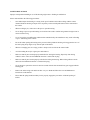
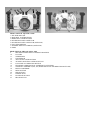
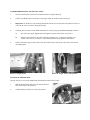
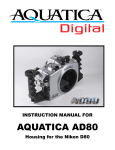
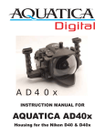
Instruction for the
AQUATICA A300 HOUSING
Table of Contents
1.
2.
2.
3.
4.
5.
6.
6.
7.
7.
8.
8.
9.
9.
10.
10.
11.
11.
11.
12.
12.
12.
12.
12/13.
Foreword
Safety Precautions
Front View of Aquatica A300
Rear View of Aquatica A300
Features
Controls in detail
Preparation of the Housing
Preparation of the Port
Preparation of the Lens
Focus Gear installation
Camera preparation and Installation
Closing of the Housing
Changing the Lens
Mounting the Port
Mounting and attaching Flashes
Taking a picture
Focus Mode
Using the Housing
Transporting your Aquatica A300
Care and maintenance
Of the Housing
Of the Ports
Of the Latches
Of the O-rings
FOREWORD
Thank you for having selected the Professional AQUATICA A300 Digital Camera Housing System for your
underwater photography.
The AQUATICA A300 Digital Housing is the result of a long and continuing relationship with the most demanding
underwater photographers in the world. Each housings is handcrafted, quality checked and pressure tested to 300 feet
by a small group of specially trained individuals, each of whom takes the utmost pride and satisfaction in offering the
best underwater camera housing in the world.
The Aquatica A300 Digital Housing was designed for optimum technical and optical performance and to provide
easy and efficient underwater access to all the functions and controls of the Canon Digital Rebel / 300D SLR.
This manual assumes that the User is already familiar with the Canon Digital Rebel / 300D camera. If not, please
read the instruction Manual before attempting to use the housing.
With basic care and maintenance, your AQUATICA D300 will give you a lifetime of enjoyment and satisfaction in
producing underwater images.
Please read this manual carefully before using your housing for the first time and note that: wherever cited the right
hand is your right when using the housing.
SAFETY PRECAUTIONS
Improper transportation handling or use of this housing might cause a flooding or malfunction.
Please read and follow the following precautions:
•
Store and transport the housing in a sturdy, shock proof container and avoid travelling with the camera
mounted inside the housing as impact forces especially on the external push buttons will be transferred to
the camera.
•
When travelling by air, either remove the port or open the housing.
•
Never change a port or open the housing in a location where sand or similar foreign material might come in
contact with an O-ring
•
Use of accessories or modifications and alterations unauthorized by the manufacturer may result in flooding
or poor functioning of the controls
•
Be careful when opening the housing as the pressure build up inside the housing will exaggerate the force of
the latch spring. Keep fingers away from the path of the latches.
•
Whenever changing ports or O-rings, perform a simple seal test with out the camera inside.
•
Avoid scratching the acrylic or glass ports and windows.
•
Make sure that all ports remain properly attached before rinsing the housing. Especially when rinsing
without a strobe make sure the Bulkhead connector is sealed with its plug.
•
Make sure that all ports remain properly sealed before rinsing the housing. When rinsing without a strobe
makes sure the Bulkhead connector is sealed with its plug.
•
Never attempt to operate the camera in auto focus mode with the lens mounted focus gear engaged with the
housing gear.
•
Remove the main O-ring seals and clean after every use. Read and follow the Care and Maintenance
instructions on this manual.
•
Ensure that the spring loaded secondary lock is properly engaged to prevent the accidental opening of
latches.
FRONT VIEW OF AQUATICA A300
1. SHUTTER RELEASE
2. MAIN DIAL CONTROL KNOB
3. MODE DIAL CONTROL KNOB
4. BULKHEAD FLASH CONNECTOR
5. BULKHEAD FLASH CONNECTOR (OPTIONAL)
6. FOCUS/ZOOM KNOB
7. STROBES ARM ATTACHMENTS (OPTIONAL)
8. GRIPS
REAR VIEW OF THE AQUATICA A300
9.
MOUNTING HOLES FOR ACCESSORY BRACKETS
10.
LATCHES
11.
VIEWFINDER
12.
TOP WINDOW
13.
AE/FE LOCK CONTROL KNOB
14.
AF POINT SELECTOR CONTROL BUTTON
15.
LCD PANEL ILLUMINATION BUTTON
16.
EXPOSURE COMPENSATION / APERTURE VALUE KNOB
17.
CROSS KEY ASSEMBLY (SET, ISO, WHITE BALANCE AND DIRECTION BUTTONS)
18.
REAR LCD WINDOW
19.
MENU BUTTON
20.
INFO BUTTON
21.
JUMP BUTTON
22.
PLAYBACK BUTTON
23.
ERASE BUTTON
FEATURES
The Aquatica A300 is the world's most technologically advanced underwater housing, ergonomically designed to
place all the essential camera controls under your finger tips and features the following:
- Large ergonomic and easy to operate controls for most of the manual and computerized camera functions.
- The essentials controls for picture taking can be easily accessed underwater, these includes:
A. Shutter release
B. Main Dial.
C. Mode Dial
D. Focus and/or Zoom
E. AE/FE control
D. AF point selection
E. LCD illumination
F. Exposure Compensation or Aperture Value
G. ISO
H. White balance
I. Menu
J. Jump function
K. Playback function
L. Erase function
-
A complete selection of bayonet mounted ports including an 8" diameter dome, flat ports, extension tubes
and rings to preserve the image quality for a wide range of Canon EF and other popular AF lenses. A 6"
diameter dome is also available but may require a + Diopter when used with lenses with a long minimum
focusing distance.
-
A complete line of lens and zoom gears and related accessories.
CONTROLS IN DETAIL
1. SHUTTER RELEASE LEVER- pulling the shutter release lever back part way activates the camera meter and
autofocus. Pulling the lever back all the way fires the camera.
2. MAIN DIAL KNOB: It rotates clockwise and counter clockwise. It can be use alone or in combination with other
controls to select or set various camera functions or modes
Refer to your camera manual.
3. MODE DIAL KNOB: Rotate to change the exposure mode (P, S, A, M) and different shooting modes .
2. HOT SHOE CONNECTOR- connects the camera to the Flash Bulkhead. Slide this Connector into the camera Hot
Shoe. When detaching do not pull the cord as this might damage the electrical connections.
3. FOCUS/ZOOM PINION GEAR- engages and operates the focus or zoom gear on the lens.
4. BULKHEAD CONNECTOR- for Flash Sync Cord. (Nikonos Type 5 pins).
5. EXTRA CONNECTOR (optional) - allows for installation of a second flash bulkhead.
6. FOCUS/ZOOM KNOB- turning allows manual focus of a single focus lens or zoom of a zoom lens.
7. STROBES ARMS ATTACHMENTS (optional) - allows the installation of strobe arms.
8. GRIPS- attached to each side of the housing to provide ease and comfort of handling
9. MOUNTING HOLE- these are 1/4-20 TPI holes that are ready to accept TLC Base Brackets or TLC Base Ball for
strobe arms or accessories.
11. VIEWFINDER: A full view of the illuminated camera viewfinder displays all necessary information.
12. TOP WINDOW – permit visual contact with Mode Dial
13. AE/FE LOCK CONTROL KNOB – screw in the knob to lock-in the AE/FE function.
14. AF POINT SELECTOR – press to select autofocus point
15. LCD PANEL ILLUMINATOR – press to illuminate rear panel LCD.
16. EXPOSURE COMPENSATION / APERTURE VALUE KNOB – screw in knob to engage exposure
compensation or aperture value selection in manual or aperture priority mode.
17. CROSS KEYS BUTTONS ASSEMBLY: These buttons have multiple uses. They allow the selection of the focus
area, in the menu mode; they are used to scroll up or down and left to right to choose from your menu selection they
are used in the delete mode and for the manual selection of ISO speed and white balance.
18. REAR LCD WINDOW: allow viewing of camera setting and images taken with the camera.
19. MENU BUTTON: push to allow access to menu.
20. INFO BUTTON: allow viewing of image’s shooting information.
21. JUMP BUTTON: press to allow the navigation between images.
22. PLAYBACK BUTTON: press to view image taken with camera.
23. ERASE BUTTON: press to engage the image deleted function
PREPARATION OF THE HOUSING
1. Attach Grip Bracket to the housing: The housing comes with two hand grips which should be installed on the
sides of the housing with the supplied screws and Allen key. Occasionally remove the grips and lubricate the screws
(see Care and Maintenance: of the housing.)
Depending on which strobe system you are using, you can mount the necessary shoes or brackets onto the 1/4"-20
threaded holes on the top of the hand grips. The AQUATICA TLC strobe arm system is recommended.
There are also 1/4"-20 threaded holes on the bottom of the housing that can be used for various mounting application
trays. As well there are two holes on top of the front half of the housing for mounting accessories.
Mount your strobes and connect the sync cord to the housing's flash bulkhead for the type of sync fitting you are
using. Be sure to read the section titled "Care and Maintenance: of the O-rings."
2. Lubricate the Main O-ring Seal: Before use, remove the Main O-ring seal from its groove on the front half of
the housing and carefully verify that the O-ring and the O-ring groove are free from scratches or foreign material.
Lubricate the O-ring with a light coat of silicone grease.
When replacing the O-ring place the entire O-ring over the O-ring groove and start by pushing the O-ring in the
corners. Work your way around the O-ring making sure the O-ring is snugly sitting in the groove.
For proper handling and maintenance of O-rings be sure to read the section titled "Care and Maintenance: of the Orings."
PREPARATION OF THE PORTS
1. Select the correct port:
Depending on whether you've decided to shoot macro or wide angle photography, you will be installing either the flat
Macro Port; acrylic port (product # 18426), or glass port (product# 18427) or 8" Dome Port (Product # 18405) or 6”
Dome Port (product# 18406). See lens chart for the suggest port and accessories.
Macro Port Extension Rings: the Macro Port will accept the EF 50mm F: 2, 8 macro or Sigma 50 F: 2.8 macro. If
you intend to use a longer lens such as the Canon EF 100mm F: 2.8 macro or the Sigma EX 105 F: 2.8 macro, you
will require # 18453 extension ring. These extension rings fit between the Macro Port and the housing to provide the
extra space necessary for the longer lens.
Dome Port Extension Rings: When using a wide angle or zoom lens, the Dome Port should be used with an
Extension Ring as follows: Refer to the Lens Chart on www.aquatica.ca for updating of lenses that can be used in the
housing.
These extension rings fit between the housing body and the Dome port to provide the optical correction needed for
each lens.
In order to reduce glare, maximize contrast and offer physical protection to the dome, the use of a dome shade
(product # 18480 for fisheye shade, and #18482 for wide angle shade) for the 8” dome or #18482 Fisheye or 18482
wide angle shade are recommended.
2. Clean the port:
Dirt, grease or fingerprints on the port especially on the inside, can adversely affect the quality of the image. Acrylic
ports should be cleaned with plastic cleaner and the glass ports should be cleaned with lens cleaner. For more details
make sure to read the section titled "Care and Maintenance: of the Ports."
3. Lubricate the port O-ring seal:
Before using the port, remove the O-ring on the rear of the port and lightly coat it with silicone grease. For more
details refer the section titled "Care and Maintenance: of the O-rings."
PREPARATION OF THE LENS
Depending on the lens used, there are a number of gear options possible. Using the right gear (s) and correctly
mounting them on the lens is very important for a smooth housing operation. Use the following chart to determine
which gear(s) to use and follow the installation directions for each gear carefully. Since the aperture control is
achieved through the Sub-Command Dial, the use of AF types of lenses is mandatory. The focus/zoom gear can vary
from one lens to the other.
Gear selection chart
PRODUCT #
18703
GEAR/LENS
Zoom gear EF 18-55mm
•
If the camera is set in autofocus, a focus gear is not required.
•
If the camera is set in manual focus or if you are using a zoom lens, a focus/zoom gear must be mounted on
the lens.
•
If you are using a zoom lens with an 8" dome port you may need to install a close-up diopter on the lens to
correct the minimum focusing distance of the lens so that it will be able to focus on the virtual image created
by the dome.
Focus Gear installation:
1.
Set the lens to minimum focus distance.
2.
Mount the focus gear over the focus ring of the lens such that the round indentation etched on the side of the
gear is facing the rear of lens and is aligned with the Distance Index of the lens (for full gears orientation is
immaterial).
3 (a)
For Slip-on gears (gears without mounting screws): Slide the gear over the lens and align the gear with the
front of the lens focusing ring.
(b)
For gears with mounting screws: Tighten the three set screws evenly. Tighten each screw approximately ½ a
turn working around the gear until all the three (3) screws are tightened, and the gear is concentric with the
lens body.
CAUTION: Do not over-tighten these screws, as this might bind the lens thus restricting the rotation of the
focus ring and/or damaging the lens. Conversely under-tightening these screws might cause the gear to slip
or lose alignment.
4.
Rotate the focus ring several times to make sure it moves smoothly and the gear does not slip before closing
the housing
Refer to the Lens Chart on www.aquatica.ca for updating of lenses that can be used in the housing.
WARNING: Never attempt to operate the camera in auto focus mode when a NON USM lens is mounted with a
focus gear. This might cause serious damage to your camera or to the lens.
CAMERA PREPARATION AND INSTALLATION
1.
Turn the camera Power switch to the ON position before closing the Housing.
2.
Set the Focus Mode Selector on the lens to the proper setting AF or MF if using a focus gear
3.
Important Note: Small “D” Clips and strap attachments that are used for the camera strap must be removed
or moved out of the way before closing the housing.
4.
Carefully place the camera on the saddle and ensure the camera is properly installed and aligned as follows:
5.
A)
The camera is properly aligned and secured against rotation or movement. See picture A
B)
Align the Tripod Socket of the camera with the mounting screw. Tighten the mounting screw
securely with a coin or screw driver, while ensuring that the camera position is not altered.
Finally, connect the trigger release cable to the side of the camera in the remote cable socket of the camera.
(See photograph)
Picture A: alignment pin
Picture B: Trigger release cable position
CLOSING OF THE HOUSING
Once the camera is secure on the saddle inside the front half of the housing, simply:
1.
Slide the housing flash cable connector onto the hot shoe
base of the camera. (See picture C)
2.
Confirm that the On/Off lever is in the ON position
Picture C: flash cable connector
Before closing the housing always ensures that:
1.
The main O-ring on the front half of the housing is clean, lubricated and properly seated for a positive seal.
2.
The sealing surface on the rear half of the housing is clean and free from any scratches or physical damage.
3.
All cords or wires are tucked in so that they do not interfere with the closing of the housing.
4.
The Function dials Knob on the rear half of housing is pulled out to allow clearance when closing the
housing.
To close the housing simply:
I.
Join the front and rear halves of the housing using the two dowel pins at the bottom of the housing as a
guide.
ii.
Hold the housing with both hands and look around the sealing surface to ensure that the O-ring remained
properly seated and that no cords, wires or "D-rings" are caught between the edges.
iii.
Close the two latches simultaneously. CAUTION: if you feel any resistance as you attempt to close the
latches, do not force the closure. Check for an obstruction and try again.
iv.
Verify that the safety locking mechanisms of the latches are properly engaged to avoid any accidental
opening.
LENS INSTALLATION
With the camera inside the housing, install the lens prepared with the gears through the port opening in the front of
the housing. Ensure that the lens mounted gears are properly installed and aligned. Rotate the focus control knobs to
ensure that the gears are properly meshed, do not grind and that their rotation is smooth.
Note: to avoid breaking the auto-focus mechanism of the camera you should set the Focus Control to “M” Manual
before testing the proper meshing of the gears.
CHANGING A LENS (REMOVING A LENS)
The lens mounted gears may restrict the view and ease of access to the lens release button of camera. A stick or a
pencil can be used to push the lens release button on the camera body
MOUNTING THE PORT
Before mounting the Port on the Housing always ensures that;
•
The port O-ring is clean, lubricated and properly seated in its groove.
•
The sealing surface on the Housing is clean and free of physical damage.
The AQUATICA A300 Housing System features a bayonet mount. To mount the port or extension ring simply:
1.
Place the housing on its back on a soft steady surface.
2.
Place the port or extension ring inside the main port of the housing. Align one of the four alignment notches
with the opening of the housing.
3.
Place your hands on opposite sides of the port or extension ring.
4.
Push on one side of the port or extension ring until you feel it snap into place. Then press the other side until
it, snaps into place. Make sure the bayonet is completely inside the housing.
5.
Finally turn the Port clockwise approximately 60 degrees until it stops. Do not force it. If there is too much
resistance take the port off, check the O-ring and retry.
6.
Check to ensure for the proper seating and sealing of the port on the housing.
Note: It is recommended that you familiarize yourself with this mount by trying it without the camera; this will allow
you to see the inside view of the bayonet mount and of the ports or extension rings in the housing.
MOUNTING AND ATTACHING FLASHES
Depending on which strobe system you are using, you can mount the necessary shoes or brackets or Base Ball onto
the threaded holes on the top of the hand grips. Use of the Aquatica TLC Strobe Arm System is recommended.
There are also two 1/4"-20 threaded holes on the bottom of the housing that can be used for various mounting
applications. For example, Aquatica TLC makes a strobe arm mounting tray that will fit on the bottom of the
housing. Two 1/4"-20 threaded holes on top of the housing will accept an Aquatica bracket or Base Ball that can hold
a small dive light or a strobe arm.
The AQUATICA A300 Digital housing is fitted with a Standard Nikonos TTL or double TTL.
•
When using the Standard Nikonos sync cord make sure to lubricate the O-ring on the sync cord's connector
with a light coat of O-ring grease. Also put a light coat of O-ring grease on the threads of this connector.
TAKING A PICTURE
Following are the basic techniques. For more information and advanced photography please study the Canon 300D /
Digital Rebel instruction manual.
1.
Turn the Function dial Knob until the desired exposure mode appears on the LCD window. Exposure Mode
options in sequence are: Depth of Field auto (A-DEP), Manual Exposure (M), Aperture Priority Auto (Av),
Shutter Priority Auto (Tv), and Programmed Auto (P), This dial also access other automatic function which
are of limited uses for underwater photography,
Note: When using a flash, it is recommended that the camera be used only in Single Frame Motor Drive or there is
the possibility that the camera will fire before the flash can recycle.
2.
3.
Pull the Shutter Release Lever partially back. This will activate the camera's meter and autofocus system.
•
If using manual focus use the Focus Knob on the housing or the flat port to focus.
(Read the warning in the "Focus Gear installation" section)
•
If using the Manual or Shutter mode adjust the Main Command Knob to set the shutter speed.
Pull the Shutter Release Lever the rest of the way until the camera fires.
FOCUS MODE
Make sure to select the focus mode (manual or auto focus) on your camera prior to the dive. The location of the
MF/AF selector on the lens prevent access trough the AQUATICA A300 Digital housing.
AF: The camera will find, lock and hold focus as long as the shutter trigger is partially depressed.
MF: You need to manually adjust the focus. The green dot in the information bar of the camera’s viewfinder
indicates the proper focus setting for the target subject.
For more detailed information concerning the operation of the different focus modes consult the Canon 300D /
Digital Rebel instruction book.
USING THE HOUSING
Whenever changing ports or O-rings, it is highly advisable to perform a simple seal test without the camera inside.
Strapping a weight to the housing and lowering the unit to a depth of 30 to 50 feet of water for at least 10 minutes
will assure you that the seating of the new port or o-ring is proper. This test, though time consuming and often
considered unnecessary, may save your camera equipment from irreparable water damage. The housing is now ready
for the dive.
CAUTION:
Never jump into the water with the housing. It is best to have the system handed to you after you have made your
entry, or have it lowered to you on a rope. Make certain that ropes of other equipment stay clear of the system.
When photographing, be sure to respect the environment. Avoid damaging marine life or manipulating sea creatures
to obtain a pleasing photo. The housing is slightly negatively buoyant so that you can lay it down on the bottom, but
avoid laying it on living coral or other delicate marine life.
Changing the memory card
Always take care to thoroughly dry the housing before opening it to replace the memory card. Wipe the housing off
with a dry towel. If possible it is suggested that the housing be blown dried by directing an air nozzle around the
main o-ring before opening.
Rest the housing on its front with the lens facing down (a dome shade is recommended to protect the acrylic dome
from scratches), release the two latches simultaneously. Lift the rear part of the housing and place it in a secure
location. This minimizes the possibility of any residual water falling into the housing and on to the camera when the
housing is opened or damage to the sealing surface.
TRANSPORTING THE AQUATICA A300
Store the AQUATICA A300 Digital housing in a sturdy, shock proof container.
When travelling by air, remove or loosen the port. This allows for equalization of the air pressure inside the housing
to the external air pressure. Failure to do so may cause serious damage to the acrylic ports. Avoid travelling with the
camera mounted in the housing. If you must do so, remove the lens as external pressure can damage the camera.
CARE AND MAINTENANCE
Of the housing:
After each and every salt water dive, your housing system should be soaked or rinsed in fresh water. The housing
system should soak in fresh water for at least 30 minutes. During this soaking period reach into the water and
operate all the controls several times.
Be sure to remove the housing's main o-ring and clean it after every use. Refer to Maintenance: Of the O-rings. To
ensure that the hand grips won't fuse on to the housing due to the exposure to salt water, it is also a good practice to
occasionally remove the hand grips. Clean and lubricate the bolts with a small amount of WD-40.
WARNING: Use WD-40 carefully, sparingly and only on metal to metal surfaces. WD-40 can damage the acrylic
on the ports, the optical surfaces on lens as well as the O-rings.
Of the Ports:
Care should be taken with the Dome Port and Macro Port to avoid scratches on the lens surface. The acrylic port is
softer than glass so minor exterior scratches are often unavoidable. However, since the indices of refraction for
acrylic and water are almost equal the scratches will not seriously impair image quality. Internal scratches (air side)
must be avoided as they do not fill in with water and will affect the quality of the image.
Clean the dome using only products recommended for cleaning acrylic such as Mirror glaze #17 Professional Plastic
Cleaner and a soft lint free cloth. Dust on the interior surfaces of the port can be removed with a soft camel hair
brush or a blower brush. Caution must be taken when using aerosol devices as not to spray the lens material with the
liquid propellant as this may seriously affect the optical properties of the port. The ports should be removed and
serviced after every dive.
Of the Latches:
The two latches of the AQUATICA A300 are designed to have a locking action to prevent accidental opening.
Always ensure that the locking mechanism is secure. Watch for the build-up of corrosion or salt residue around the
latches. This will appear as a white material. Lubricate the latches with a small amount of WD-40 to remove the
corrosion or salt residue build-up.
Of the O-Rings:
The O-rings that need to be maintained on a regular basis are the main housing O-ring and the O-ring on the lens
port.
The main O-ring should be cleaned on a daily basis and the port O-ring should be cleaned daily or each time the port
is changed.
TO SERVICE O-RINGS
Of the housing Main O-Ring, Ports and Extension Rings
1.
Remove the O-ring. It is important never to use a sharp instrument when removing an O-ring as this may
damage the O-ring groove or the O-ring itself. A bobby pin or edge of a credit card works well.
2.
Once the O-ring is removed, it should be examined for damage. Check to make sure that the O-ring is free
of nicks and cuts and that it retains its original round profile. O-rings that appear to be damaged should be
discarded immediately and replaced with new O-rings.
3.
Rinse the O-ring with fresh water and dry it with a clean lint free cloth.
4.
Clean the O-ring groove (where the O-ring sits) with a Q-tip. Be sure to remove any lint the Q-tip may leave
behind. Inspect the groove for damage.
5.
Wipe the part of the housing that the O-ring seals against with a clean lint-free cloth.
6.
Re-grease the O-ring with a thin layer of O-ring grease until it appears to be smooth and shiny. Do not over
grease it. Use just enough grease so the O-ring will pull smoothly through your fingers. Excessive amounts
of grease will only serve to attract dirt to the o-ring.
7.
Make sure that the O-ring is properly (evenly) installed in the O-ring groove.
8.
To reinstall the clean and lubricated O-ring, place the entire O-ring over the groove and start by pushing the
O-ring in at each corner then, push the O-ring at each side and finally, work in the rest of the O-ring. Never
start at one end and work your way around the O-ring. This places uneven tension on the O-ring which may
cause the O-ring to stretch resulting in excess O-ring, which will have no place to go.
There are internal O-rings on the housing controls as well. These O-rings are not as susceptible to damage as they are
not exposed but they do require yearly maintenance and are not user serviceable. The housing should be returned to
AQUATICA or to an authorized AQUATICA service facility for this annual maintenance.
Check the Web site www.aquatic.ca for the closest service center.
An internal moisture alarm is available for your AQUATICA A300 housing (Product # 18796). This alarm is
available through your authorized AQUATICA dealer and can be easily installed.
WARRANTY
All AQUATICA products are guaranteed against defects in material or workmanship for (1) one full year from the
date of purchase for consumer use. These same products when used commercially will carry a 90-day warranty. No
statutory warranty applies. Camera housed in AQUATICA housings are not covered under this warranty and ANY
WATER DAMAGE SUSTAINED DUE TO INSTALLATION ERROR OR FOR ANY OTHER REASON IS
NOT THE RESPONSIBILITY OF AQUATICA. Therefore the appropriate insurance should be maintained by the
user"