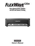
1
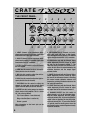
C R AT E
CONGRATULATIONS!
You are now the proud owner of the Crate TX50D battery powered
amplifier with Digital Signal Processing. At last, you can take your music
with you and have great tone on the road. Not only is the TX50D compact
and portable, it also sports two separate channels and the incredible
sound that has made Crate a household name among musicians.
Your Crate amplifier is designed by musicians and built using the finest
components available. Each unit is rigorously tested by skilled technicians
and musicians to ensure that your amplifier is the best it can be!
In order to get the most out of your new amplifier, we strongly urge you
to go over the information contained in this manual before you begin
playing.
Thanks for choosing
CRATE.
CONTENTS:
Features . . . . . . . . . . . . . . . . . . . . . . . . . . . . .3
About the Power Supply . . . . . . . . . . . . . . .4,5
The Front Panel . . . . . . . . . . . . . . . . . . . . . .6,7
The Rear Panel . . . . . . . . . . . . . . . . . . . . . . .8
About the Insert Jack . . . . . . . . . . . . . . . . . . .8
Suggested Setups . . . . . . . . . . . . . . . . . . .9,10
System Block Diagram . . . . . . . . . . . . . . . . . .11
Technical Specifications . . . . . . . . .back cover
CAUTION
PRECAUCION
ATTENTION
RISK OF ELECTRIC SHOCK
DO NOT OPEN
RIESGO DE CORRIENTAZO
NO ABRA
RISQUE D'ELECTROCUTION
NE PAS OUVRIR
WARNING: TO REDUCE THE RISK OF FIRE OR ELECTRIC
SHOCK, DO NOT EXPOSE THIS APPARATUS TO RAIN OR MOISTURE. TO REDUCE THE RISK OF ELECTRIC SHOCK, DO NOT
REMOVE COVER. NO USER-SERVICEABLE PARTS INSIDE.
REFER SERVICING TO QUALIFIED SERVICE PERSONNEL.
PRECAUCION: PARA REDUCIR EL RIESGO DE INCENDIOS O DESCARGAS
ELECTRICAS, NO PERMITA QUE ESTE APARATO QUEDE EXPUESTO A LA
LLUVIA O LA HUMEDAD. PARA DISMINUOIR EL RIESGO DE CORRIENTAZO.
NO ABRA LA CUBIERTA. NO HAY PIEZAS ADENTRO QUE EL USARIO PUEDO
REPARAR DEJE TODO MANTENIMIENTO A LOS TECHNICOS CALIFICADOS.
ATTENTION: PROTÉGEZ CET APPAREIL DE LA PLUIE ET DE L'HUMIDITÉ
AFIN D'ÉVITER TOUT RISQUE D'INCENDIE OU D'ÉLECTROCUTION. POUR
REDUIRE D'ELECTROCUTION NE PAS ENLEVER LE COUVERCLE. AUCUNE
PIECE INTERNE N'EST REPRABLE PAR L'UTILISATEUR. POUR TOUTE
REPARATION, S'ADRESSER A UN TECHNICIEN QUALIFIE.
IMPORTANT SAFETY INSTRUCTIONS
• READ, FOLLOW, HEED, AND KEEP ALL INSTRUCTIONS AND WARNINGS.
• DO NOT OPERATE NEAR ANY HEAT SOURCE AND DO NOT BLOCK ANY VENTILATION OPENINGS ON THIS APPARATUS. FOR PROPER OPERATION,
THIS UNIT REQUIRES 3” (75mm) OF WELL VENTILATED SPACE AROUND HEATSINKS AND OTHER AIR FLOW PROVISIONS IN THE CABINET.
• DO NOT USE THIS APPARATUS NEAR SPLASHING, FALLING, SPRAYING, OR STANDING LIQUIDS.
• CLEAN ONLY WITH LINT-FREE DAMP CLOTH AND DO NOT USE CLEANING AGENTS.
• ONLY CONNECT POWER CORD TO A POLARIZED, SAFETY GROUNDED OUTLET WIRED TO CURRENT ELECTRICAL CODES AND COMPATIBLE WITH
VOLTAGE, POWER, AND FREQUENCY REQUIREMENTS STATED ON THE REAR PANEL OF THE APPARATUS.
• PROTECT THE POWER CORD FROM DAMAGE DUE TO BEING WALKED ON, PINCHED, OR STRAINED.
• UNPLUG THE APPARATUS DURING LIGHTNING STORMS OR WHEN UNUSED FOR LONG PERIODS OF TIME.
• ONLY USE ATTACHMENTS, ACCESSORIES, STANDS, OR BRACKETS SPECIFIED BY THE MANUFACTURER FOR SAFE OPERATION AND TO AVOID INJURY.
• WARNING: TO REDUCE THE RISK OF ELECTRIC SHOCK OR FIRE, DO NOT EXPOSE THIS UNIT TO RAIN OR MOISTURE.
• SERVICE MUST BE PERFORMED BY QUALIFIED PERSONNEL.
• OUR AMPLIFIERS ARE CAPABLE OF PRODUCING HIGH SOUND PRESSURE LEVELS. CONTINUED EXPOSURE TO HIGH SOUND PRESSURE LEVELS
CAN CAUSE PERMANENT HEARING IMPAIRMENT OR LOSS. USER CAUTION IS ADVISED AND EAR PROTECTION IS RECOMMENDED IF UNIT IS
OPERATED AT HIGH VOLUME.
• WARNING: THIS UNIT REQUIRES A SAFETY GROUNDED OUTLET WIRED TO CURRENT ELECTRIC CODES HAVING THE LINE SUPPLY VOLTAGE,
POWER, AND FREQUENCY IDENTIFIED ON THE REAR OF THE UNIT. THE OUTLET MUST REMAIN ACCESSIBLE TO DISCONNECT THE UNIT IF A
FAULT SHOULD ARISE WHILE IN USE. THIS UNIT SHOULD BE UNPLUGGED WHEN NOT IN USE.
EXPLANATION OF GRAPHICAL SYMBOLS:
EXPLICACION DE SIMBOLOS GRAFICOS:
EXPLICATION DES SYMBÔLES GRAPHIQUES:
"DANGEROUS VOLTAGE"
=
“VOLTAJE PELIGROSO”
"DANGER HAUTE TENSION"
"IT IS NECESSARY FOR THE USER TO REFER TO THE INSTRUCTION MANUAL"
=
“ES NECESARIO QUE EL USUARIO SE REFIERA AL MANUAL DE INSTRUCCIONES.”
"REFERREZ-VOUS AU MANUAL D'UTILISATION"
C R AT E
FEATURES:
• Two separate channels
• Crate’s Digital Signal Processing (DSP)
• Insert jack for connecting external effects
• CD Inputs for connecting background music
• Footswitch control of channel selection and DSP on/off
• Headphones jack for silent operation
• Internal rechargeable power supply for up to 8 hours of normal playing time, 2 hours at full output – fully recharges within 6 hours (when
battery is fully discharged; shorter if partially charged)
• Can also be powered by an AC wall adapter (supplied) or by a 12 volt
vehicle car adapter (included – see page 5)
• Two-color battery status LED – red indicates low battery, yellow indicates battery okay
• Tuned port cabinet for extended bass response; 10” woofer and 2”
Piezo tweeter for full range sound with clear highs
• Durable black or platinum Tolex® covering
• Complete set of rubber feet on three different sides – for positioning
as a low angle monitor, a high angle monitor or as an upright speaker
(see below)
• Stand mount adapter (1-1/2” diameter) for PA use (see below)
LOW ANGLE MONITOR
HIGH ANGLE MONITOR
UPRIGHT SPEAKER
STAND MOUNTED SPEAKER
3
C R AT E
ABOUT THE POWER SUPPLY:
The TX50D uses a sealed lead-acid 12-volt battery as its internal power
source. Unlike ni-cad batteries, this battery has no “memory” – it can
be fully recharged at any time, without damage to the battery.
When fully charged, the LED next to the power switch will glow yellow
with the switch at the on (“I”) position. The LED will change to red
when the battery is low and needs recharging. When this happens, turn
the amp off, connect the 15-volt charger to the charger jack and plug it
in. The LED near the charger jack will glow red while the amp is charging and goes out when the amp is fully charged. The battery fully
recharges within 6 hours, providing up to 8 hours of use at low levels,
about 4 hours of use at moderate levels, and about 2 hours of use at
continuous full power (sine wave). The battery is rated for up to 1000
charging cycles. The charger can also function as an AC power supply.
The battery inside the TX50D must be fully charged before operating
the amplifier for the first time. Even though the amplifier leaves our
factory with a charged battery, time spent in shipping may cause the
battery to lose some of its charge.
WARNING! Never connect the supplied 15VDC charger
to the amplifier’s 12VDC Cigarette Lighter Adapter jack!
Damage to the amplifier may occur!
NOTE: If the battery is drained too low, the Power LED will go out. This
indicates an exhausted battery – one which may not take a charge. If
this happens, turn the amp off, connect the 15-volt charger to the
charger jack and plug it in. If the Charger LED (see #25, page 8) doesn’t
illuminate, the battery might be beyond recharging. (The TX50D uses a
“smart” charging circuit and will not allow you to charge a defective
battery.) If the battery is serviceable, the LED will glow once the battery
reaches 10 volts – leave the charger plugged in and let the battery fully
recharge. If the LED never illuminates, the battery may need replacing.
Contact Crate’s service department:
SLM Electronics
1901 Congressional Drive
St. Louis, MO 63146
1-800-738-PARTS (7563)
4
C R AT E
ABOUT THE POWER SUPPLY (continued):
The TX50D may also be powered by using a 12-volt vehicle cigarette
lighter adapter, available at most electronic supply stores. Make certain
that the polarity on the adapter matches what is shown below.
POSITIVE
NEGATIVE
Connect the small round end of the adapter to the 12VDC Automobile
adapter jack (#26, page 8), then plug the other end of the adapter into
the vehicle’s cigarette lighter socket. (In some vehicles, the ignition
switch must be in the “on” or “accessory” position to have power at the
socket.) NEVER PLUG THE SUPPLIED 15VDC CHARGER INTO THE
AMPLIFIER’S 12VDC LIGHTER PLUG!
When using the DC cigarette lighter adapter, the vehicle’s battery will
keep the amp charged to its voltage level – if the battery has a 13.5-volt
charge, the amp will charge up to 13.5 volts; if the battery is low and
only has a 10-volt charge, the amp will discharge down to 10 volts.
CAUTION! The TX50D contains a sealed, rechargeable,
lead-acid battery. Improper disposal of battery or replacement with any other type may cause leakage, explosion,
and/or injury. See page 4 for additional information. Also,
refer to product warranty information.
This equipment has been tested and found to comply with the limits for a Class B digital device, pursuant to part 15 of the FCC
Rules. These limits are designed to provide reasonable protection against harmful interference in a residential installation. This
equipment generates, uses and can radiate radio frequency energy and, if not installed and used in accordance with the
instructions, may cause harmful interference to radio communications. However, there is no guarantee that interference will
not occur in a particular installation. If this equipment does cause harmful interference to radio or television reception, which
can be determined by turning the equipment off and on, the user is encouraged to try to correct the interference by one or more
of the following measures:
• Reorient or relocate the receiving antenna.
• Increase the separation between the equipment and the receiver.
• Connect the equipment into an outlet on a circuit different from that to which the receiver is connected.
• Consult the dealer or an experienced radio/TV technician for help.
Changes or modifications to this device not expressly approved by SLM Electronics could void the user’s authority to operate
the equipment under FCC rules.
Declaration of Conformity
Manufacturer’s Name: SLM Electronics
Corporate Headquarters: 1901 Congressional Drive, St. Louis, Missouri 63146
Primary Production Facility: 700 Hwy 202 W, Yellville, Arkansas, 72687
Product Type: Audio Amplifier
Products meet the regulations for compliance marking under:
ETL standards UL6500, UL60065, or UL813
CSA standards E60065 or C22.2 No.1-M90
CE safety standard EN60065
CE EMC standards EN55103 or EN55013 and EN61000
C-tick designation Level 2, ABN #56748810738, ARBN# N222
KETI standard K60065 (limited model approval)
Compliance Support Contact: SLM Electronics, Attn: R&D Compliance Engineer
1901 Congressional Drive, St Louis, Missouri, 63146 • Tel.: 314-569-0141, Fax: 314-569-0175
5
C R AT E
THE FRONT PANEL:
1
2
3
9
10
11
1. LOW Z: Connect a low impedance microphone here by means of a shielded signal cable
terminated with an XLR type connector.
2. HIGH Z: Connect a high impedance microphone here by means of a shielded signal cable
terminated with a 1/4” connector.
3. LEVEL: Use this control to adjust the level of
the mic channel.
4. LOW: Use this control to adjust the low frequency level for the mic channel.
5. MID: Use this control to adjust the mid frequency level for the mic channel.
6. HIGH: Use this control to adjust the high frequency level for the mic channel.
7. DSP SEND: Use this control to adjust the
amount of signal sent to the internal Digital
Signal Processor (DSP) for the mic channel.
8. INSERT: Use this jack to connect an external
effects device to the amplifier. This is a stereo
1/4” jack, wired as follows:
Tip = Line In (Return - from effect out)
Ring = Line Out (Send - to effect in)
Sleeve = ground
More information on the Insert jack can be
found on page 8.
6
4
5
6
7
12 13 14
15
16
9. INSTRUMENT INPUT: Connect an instrument, tape player, CD player, or high impedance microphone here by means of a shielded
signal cable terminated with a 1/4” connector.
10: GAIN (Active only with the Channel Select
switch depressed): Use this control to adjust
the gain for the instrument channel 1 – the
lower the setting, the lower the amount of distortion. As this control is rotated clockwise, the
distortion increases and the output signal
becomes louder.
11: SHAPE (Active only with the Channel Select
switch depressed): Use this control to adjust
the tone of the instrument channel 1. Rotating
this control counter clockwise enhances mid
frequencies; rotating it clockwise enhances the
low and high frequencies.
12: LEVEL (Active only with the Channel Select
switch depressed): Use this control to adjust
the output level of the instrument channel 1.
13. CHANNEL SELECT: Use this switch to
select channel 1 or 2 for the instrument input.
With this switch depressed, the Gain, Shape,
and Level controls (#10 – 12) are active. With this
switch in the out position, the Low, Mid, High,
and Level controls (#14 – 17) are active. Channel
1 is typically used for electric guitars since the
Gain control can be cranked to produce heavily
overdriven distortion.
C R AT E
8
17
18
19
20
21
14. LOW (Active only with the Channel Select
switch out): Use this control to adjust the low
frequency level for the instrument channel 2.
15. MID (Active only with the Channel Select
switch out): Use this control to adjust the mid
frequency level for the instrument channel 2.
16. HIGH (Active only with the Channel Select
switch depressed): Use this control to adjust
the high frequency level for the instrument
channel 2.
17. LEVEL (Active only with the Channel Select
switch out): Use this control to adjust the output level of the instrument channel 2.
18. DSP SEND: Use this control to adjust the
amount of signal sent to the internal Digital
Signal Processor (DSP) for the instrument
channel.
19. DSP MODE: Use this control to select the
type of Digital Signal Processing (DSP) effect
applied to the signal. The nomenclature around
the control is as follows:
BYPASS: No effect applied
SLAP: Moderate slapback delay
DELAY: Moderate delay with regeneration
ECHO: Long delay with regeneration
CHORUS: Moderate chorus effect
ROTARY: Simulated rotating speaker effect
CHO/HALL: Chorus combined with large reverb
22 23
24
ROOM: Small reverb effect
HALL: Large reverb effect
20. CD INPUT: Use these jacks to connect the
outputs of a CD player or tape player to the
amplifier. The output of the CD or tape player
may need to be attenuated for a suitable mix
with the input channels – see the notes on page
10.
21. FOOTSWITCH: Use this jack to connect a
footswitch to the amplifier for remote control of
the Instrument channel selection and turning
the DSP on and off. The jack is wired as follows:
Tip = Instrument channel selection
Ring = DSP control
Sleeve = ground
22. HEADPHONES: Use this jack to connect a
pair of stereo headphones for private practice
sessions. The internal speakers are disconnected when headphones are used.
23. LED: This LED illuminates yellow when the
power switch is at the on position – when the
amp is fully charged. The LED illuminates red
when the battery needs recharging.
24. POWER: Use this switch to turn the amplifier on (top of the switch depressed) and off (bottom of switch depressed).
7
C R AT E
THE REAR PANEL:
DC CHARGER
PLUG
DC CIGARETTE
LIGHTER ADAPTOR
LIT WHEN
CHARGING
15V DC
12V DC
25
26
POSITIVE
NEGATIVE
26. DC CIGARETTE LIGHTER ADAPTER, 12
VDC: Plug the small round connector of the
optional 12-volt car adapter into this jack to
play the amplifier from a vehicle, without
using the internal battery. NEVER connect
the supplied 15-volt charger to this jack!
See page 4 for additional information.
25. DC CHARGER PLUG, 15VDC: Plug the
small round connector of the supplied AC
wall adapter into this jack to charge the
internal battery. The LED next to the jack
glows red when the amp is charging. See
page 4 for additional information.
ABOUT THE INSERT JACK:
The Insert jack (#8) lets you patch external effects into the amplifier just prior to its power amp
stage, as shown below. Set the mix controls on the external effects units to “full effect” (100% wet).
Connecting to the effect’s
insert jack with a stereo cable:
TO
INSERT,
TX-50D
TIP: LINE IN (RETURN)
RING: LINE OUT (SEND)
SLEEVE: GROUND
Connecting to the effect with a
stereo-to-mono Y-cable:
TO
INSERT,
TX-50D
TIP: LINE IN (RETURN)
TO
INSERT,
TX-50D
RING: LINE OUT (SEND)
SLEEVE: GROUND
RING: LINE OUT (SEND)
SLEEVE: GROUND
DUAL MONO 1/4" TO
STEREO 1/4" ADAPTER
RING
DUAL MONO 1/4" TO
STEREO 1/4" Y-CABLE
RING
TIP
(IF EFFECT IS INVERTING)
TIP: LINE IN (RETURN)
YPP117
STP201, 3'
STP202, 6'
STP203, 9'
TIP
(IF EFFECT IS NON-INVERTING)
STEREO 1/4" TO
STEREO 1/4" CABLE
Connecting to the effect with a
stereo-to-mono adapter and cables:
MONO 1/4" TO
MONO 1/4" CABLES
TO
STANDARD
INSERT
JACK OF
EFFECT
8
TO
INVERTED
INSERT
JACK OF
EFFECT
TO
MONO
OUTPUT
JACK OF
EFFECT
TO
MONO
INPUT
JACK OF
EFFECT
TO
MONO
OUTPUT
JACK OF
EFFECT
TO
MONO
INPUT
JACK OF
EFFECT
C R AT E
SUGGESTED SET-UPS:
The TX50D can be used in a variety of different ways, some of which are
shown below and on the following page. Use these ideas to fuel your
imagination for the setup which best suits your needs.
Idea 1 – Play and sing, with external effects and backup: Connect a microphone to the Low Z jack. Connect an instrument (acoustic or electric guitar, keyboard) to the Instrument Input jack. (This high-Z input works with
all types of pickups, from Piezo to active types.) Connect a rhythm
machine to the CD Input jacks. A two-button footswitch may be used to
select Instrument Channel 1 or 2 and to turn the DSP on and off. Connect
the external effects device to the Insert jack using one of the methods
shown on page 8. (Note that the external effect will be applied equally to
both channels, as well as the CD inputs, so use with discretion.)
MIC
LOW Z
INPUT
INSTRUMENT
EFFECTS
(SM1-SP)
INSTRUMENT
INPUT
INSERT
FOOTSWITCH
(CFP2)
CD
INPUT
RHYTHM MACHINE
FOOT
SWITCH
Idea 2 – Play along: Connect an instrument (acoustic or electric guitar,
keyboard) to the Instrument Input jack. Connect a tape player or CD player to either the CD Input jacks or to the Low Z jack of the remaining
channel. (See the notes on page 10 for more detailed infromation.) A pair
of stereo headphones may be connected to the Headphones jack for privacy.
INSTRUMENT
INSTRUMENT
INPUT
HEADPHONES
TAPE PLAYER
HI Z
INPUT
CD PLAYER
CD
INPUT
HEAD
PHONES
9
C R AT E
SUGGESTED SET-UPS (continued):
Idea 3 – Sing along: Connect a low impedance microphone to the Low Z
jack. Connect a high impedance microphone to the Instrument Input jack.
Connect a tape player (for sound tracks and back up music) to the CD
Input jacks. A single button footswitch may be used to turn the DSP on
and off.
MIC 1
MIC 2
LOW Z
INPUT
INSTRUMENT
INPUT
CD
INPUT
TAPE PLAYER
FOOTSWITCH
(CFP1)
FOOT
SWITCH
Notes:
• When a tape player or CD player is connected to the CD Input jacks,
the output of the player may need to be adjusted by means of its output level control (if it has one), or by an external attenuator/preamp.
• A tape player or CD player may be connected to either channel instead
of to the CD Input jacks. This provides control of the gain and equalization of the signal, as well as the application of DSP if desired. In this
case, the left and right outputs of the tape or CD player must be
summed to create a mono signal, such as shown below.
RIGHT
OUT
TO INPUT JACK
CA9Y
DUAL RCA-TO-MONO
1/4" ADAPTER
LEFT
OUT
10
C R AT E
SYSTEM BLOCK DIAGRAM:
SHAPE
INSTRUMENT
CHANNEL
CHANNEL
SELECT
1
LEVEL
GAIN
2
TONES
DSP
SEND
CD
INPUTS
LEVEL
LOW MID HIGH
FOOTSWITCH
DSP/CH. SELECT
DSP
RETURN
(FOOT
SWITCH
ONLY)
MIC
CHANNEL
TONES
DSP
SEND
LEVEL
DSP
LOW MID HIGH
MODE
POWER
AMP
HEAD
PHONES
INSERT
POWER SUPPLY
DC
CHARGER
SPEAKERS
DC
CIGARETTE
LIGHTER
ADAPTER
FUSE
SMART
CHARGER
CHARGING
CIRCUIT
FUSE
CHARGING
INDICATOR
BATTERY
INDICATOR
BATTERY
11
C R AT E
TECHNICAL SPECIFICATIONS
OUTPUT POWER RATING
50W RMS @ 10% THD, 4 ohms, 13.6VDC in
INPUT IMPEDANCE
1M ohm
MAXIMUM SIGNAL ACCEPTED
Mic Low Z
2V peak to peak
Mic Hi Z
12V peak to peak
Instrument
12V peak to peak
GAIN
Mic
Instrument
57dB High Z, 72dB Low Z
44dB w/Gain switch out, Ch2
85dB w/Gain switch in, Ch1
SENSITIVITY
Mic
Instrument
3.5mV RMS High Z, 20mV RMS Low Z
80mV RMS w/Gain switch out, Ch2
.8mV RMS w/Gain switch in, Ch1
400mV RMS
Line In Insert
EQS, MIC
Low
Mid
High
±15dB @ 60Hz
±15dB @ 600Hz
±15dB @ 10kHz
EQS, INSTRUMENT
Low
Mid
High
Shape
12.5dB range @ 80Hz
18dB range @ 800Hz
18dB range @ 10kHz
Crate proprietary circuit
INSERT JACK
Tip
Ring
Sleeve
Line In
Line Out
Ground
SPEAKERS
Woofer
Crate Custom Design 10”, 4 ohm, 100 watt
1.5” voice coil, 16 oz magnet
2” Piezo , 4 ohm, 150 watt network
Tweeter
POWER REQUIREMENTS
Internal 12 volt DC power supply
DC adapter for use with 120VAC
Optional 12V vehicle lighter adapter
SIZE AND WEIGHT
15-1/2”W x 13”H x 12”D; 32 lbs.
The TX50D is covered with a durable Tolex® material. To keep the cabinet in top
condition, wipe it clean with a damp, lint-free cloth to remove dirt and road film.
Never spray cleaning agents directly onto the cabinet, and stay away from abrasive cleansers which could damage the finish.
Crate continually develops new products, as well as improves existing ones. For this reason,
the specifications and information in this manual are subject to change without notice.
www.crateamps.com
©2001 SLM Electronics • A division of St. Louis Music
1400 Ferguson Avenue • St. Louis, MO 63133
P/N 47-099-03 • 061505