1
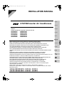
00_CV_3PN09042-1A.fm Page 1 Thursday, March 6, 2008 7:22 PM
INSTALLATION MANUAL
English
SYSTEM Inverter Air Conditioners
Deutsch
MODELS
Ceiling-mounted duct type low static pressure unit
FXDQ20PBVE
FXDQ25PBVE
FXDQ32PBVE
FXDQ40NBVE
FXDQ50NBVE
FXDQ63NBVE
FXDQ20PBVET
FXDQ25PBVET
FXDQ32PBVET
FXDQ40NBVET
FXDQ50NBVET
FXDQ63NBVET
Français
Español
Italiano
ÅëëçíéêÜ
READ THESE INSTRUCTIONS CAREFULLY BEFORE INSTALLATION.
KEEP THIS MANUAL IN A HANDY PLACE FOR FUTURE REFERENCE.
Nederlands
LESEN SIE DIESE ANWEISUNGEN VOR DER INSTALLATION SORGFÄLTIG DURCH.
BEWAHREN SIE DIESE ANLEITUNG FÜR SPÄTERE BEZUGNAHME GRIFFBEREIT AUF.
LIRE SOIGNEUSEMENT CES INSTRUCTIONS AVANT L’INSTALLATION.
CONSERVER CE MANUEL A PORTEE DE MAIN POUR REFERENCE ULTERIEURE.
Portugues
LEA CUIDADOSAMENTE ESTAS INSTRUCCIONES ANTES DE INSTALAR.
GUARDE ESTE MANUAL EN UN LUGAR A MANO PARA LEER EN CASO DE TENER ALGUNA
DUDA.
Ðóññêèé
PRIMA DELL’INSTALLAZIONE LEGGERE ATTENTAMENTE QUESTE ISTRUZIONI.
TENERE QUESTO MANUALE A PORTATA DI MANO PER RIFERIMENTI FUTURI.
ÄΙΑΒΑΣΤΕ ΠΡΟΣΕΚΤΙΚΑ ΑΥΤΕΣ ΤΙΣ ΟÄΗΓΙΕΣ ΠΡΙΝ ΑΠΟ ΤΗΝ ΕΓΚΑΤΑΣΤΑΣΗ ΕΧΕΤΕ ΑΥΤΟ ΤΟ
ΕΓΧΕΙΡΙÄΙΟ ΕΥΚΑΙΡΟ ΓΙΑ ΝΑ ΤΟ ΣΥΜΒΟΥΛΕΥΕΣΤΕ ΣΤΟ ΜΕΛΛΟΝ.
LEES DEZE INSTRUCTIES ZORGVULDIG DOOR VOOR INSTALLATIE. BEWAAR DEZE HANDLEINDING WAAR U HEM KUNT TERUGVINDEN VOOR LATERE NASLAG.
LEIA COM ATENÇÃO ESTAS INSTRUÇÕES ANTES DE REALIZAR A INSTALAÇÃO.
MANTENHA ESTE MANUAL AO SEU ALCANCE PARA FUTURAS CONSULTAS.
ПЕРЕД НАЧАЛОМ МОНТАЖА ВНИМАТЕЛЬНО ОЗНАКОМЬТЕСЬ С ДАННЫМИ
ИНСТРУКЦИЯМИ. СОХРАНИТЕ ДАННОЕ РУКОВОДСТВО В МЕСТЕ, УДОБНОМ ДЛЯ
ОБРАЩЕНИЯ В БУДУЩЕМ.
MONTAJDAN ÖNCE BU TALÝMATLARI DÝKKATLÝ BÝR BÝÇÝMDE OKUYUN.
GELECEKTE BAÞVURMAK ÜZERE BU ELKÝTABINI KOLAY ULAÞABÝLECEÐÝNÝZ BÝR YERDE
MUHAFAZA EDÝN.
EN60335-2-40,
FXDQ20NVE, FXDQ25NVE, FXDQ32NVE, FXDQ40NVE, FXDQ50NVE, FXDQ63NVE
FXDQ20NAVE, FXDQ25NAVE, FXDQ32NAVE, FXDQ40NAVE, FXDQ50NAVE, FXDQ63NAVE
FXDQ20NVET, FXDQ25NVET, FXDQ32NVET, FXDQ40NVET, FXDQ50NVET, FXDQ63NVET
FXD20MVE, FXD25MVE, FXD32MVE, FXD40MVE, FXD50MVE, FXD63MVE
FXD20MVET, FXD25MVET, FXD32MVET, FXD40MVET, FXD50MVET, FXD63MVET
FXF25LVE, FXF32LVE, FXF40LVE, FXF50LVE, FXF63LVE, FXF80LVE, FXF100LVE, FXF125LVE
FXFQ25MVE, FXFQ32MVE, FXFQ40MVE, FXFQ50MVE, FXFQ63MVE, FXFQ80MVE,
FXFQ100MVE, FXFQ125MVE
DAIKIN INDUSTRIES, LTD.
Noboru Murata
Manager Quality Control Department
1st of February 2008
Low Voltage 2006/95/EC
Machinery Safety 98/37/EC
Electromagnetic Compatibility 2004/108/EC
Umeda Center Bldg., 2-4-12, Nakazaki-Nishi,
Kita-ku, Osaka, 530-8323 Japan
FXDQ20NAVEF, FXDQ25NAVEF, FXDQ32NAVEF
FXDQ20PVE, FXDQ25PVE, FXDQ32PVE
FXDQ20PVET, FXDQ25PVET, FXDQ32PVET
FXD20PVE, FXD25PVE, FXD32PVE
FXD20PVET, FXD25PVET, FXD32PVET
FXDQ20PBVE, FXDQ25PBVE, FXDQ32PBVE, FXDQ40NBVE, FXDQ50NBVE, FXDQ63NBVE
FXDQ20PBVET, FXDQ25PBVET, FXDQ32PBVET, FXDQ40NBVET, FXDQ50NBVET, FXDQ63NBVET
0305020101
TÜV
DAIKIN.TCF.022
3PN06757-1B.fm Page 1 Saturday, March 15, 2008 9:38 AM
3PN06757-1B
01_EN_3PN09042-1A.fm Page 1 Friday, March 21, 2008 7:21 PM
VRV SYSTEM Inverter Air Conditioners
CONTENTS
1.
2.
3.
4.
5.
6.
7.
8.
9.
10.
11.
1.
SAFETY PRECAUTIONS................................................ 1
BEFORE INSTALLATION ................................................ 2
SELECTING INSTALLATION SITE ................................. 3
PREPARATIONS BEFORE INSTALLATION.................... 4
INDOOR UNIT INSTALLATION ....................................... 5
REFRIGERANT PIPING WORK ..................................... 5
DRAIN PIPING WORK .................................................... 7
INSTALLING THE DUCT................................................. 9
ELECTRIC WIRING WORK ............................................ 9
WIRING EXAMPLE ....................................................... 10
FIELD SETTING AND TEST RUN ................................ 13
SAFETY PRECAUTIONS
Please read these “SAFETY PRECAUTIONS” carefully before
installing air conditioning equipment and be sure to install it correctly.
After completing installation, conduct a trial operation to check
for faults and explain to the customer how to operate the air conditioner and take care of it with the aid of the operation manual.
Ask the customer to store the installation manual along with the
operation manual for future reference.
This air conditioner comes under the term “appliances not
accessible to the general public”.
This unit is a class A product. In a domestic environment this
product may cause radio interference in which case the user
may be required to take adequate measures.
Meaning of WARNING and CAUTION notices
WARNING ............. Failure to follow these instructions
properly may result in personal injury
or loss of life.
CAUTION .............. Failure to observe these instructions
properly may result in property damage or personal injury, which may be
serious depending on the circumstances.
•
•
•
•
•
WARNING
Ask your dealer or qualified personnel to carry out installation
work.
Do not attempt to install the air conditioner yourself. Improper
installation may result in water leakage, electric shocks or
fire.
Install the air conditioner in accordance with the instructions
in this installation manual.
Improper installation may result in water leakage, electric
shocks or fire.
Consult your local dealer regarding what to do in case of
refrigerant leakage. When the air conditioner is to be
installed in a small room, it is necessary to take proper measures so that the amount of any leaked refrigerant does not
exceed the concentration limit in the event of a leakage.
Otherwise, this may lead to an accident due to oxygen depletion.
Be sure to use only the specified accessories and parts for
installation work.
Failure to use the specified parts may result in the unit falling,
water leakage, electric shocks or fire.
Install the air conditioner on a foundation strong enough to
withstand the weight of the unit.
A foundation of insufficient strength may result in the equipment falling and causing injury.
English
Installation manual
• Carry out the specified installation work after taking into
account strong winds, typhoons or earthquakes.
Failure to do so during installation work may result in the unit
falling and causing accidents.
• Make sure that a separate power supply circuit is provided for
this unit and that all electrical work is carried out by qualified
personnel according to local laws and regulations and this
installation manual.
An insufficient power supply capacity or improper electrical
construction may lead to electric shocks or fire.
• Make sure that all wiring is secured, the specified wires are used,
and that there is no strain on the terminal connections or wires.
Improper connections or securing of wires may result in
abnormal heat build-up or fire.
• When wiring the power supply and connecting the remote
controller wiring and transmission wiring, position the wires
so that the control box lid can be securely fastened.
Improper positioning of the control box lid may result in electric shocks, fire or the terminals overheating.
• If refrigerant gas leaks during installation, ventilate the area
immediately.
Toxic gas may be produced if the refrigerant comes into contact with fire.
• After completing installation, check for refrigerant gas leakage.
Toxic gas may be produced if the refrigerant gas leaks into
the room and comes into contact with a source of fire, such
as a fan heater, stove or cooker.
• Be sure to switch off the unit before touching any electrical
parts.
• Do not touch the switch with wet fingers.
Touching the switch with wet fingers can cause electric shock.
• Be sure to earth the air conditioner.
Do not earth the unit to a utility pipe, lightning conductor or
telephone earth lead.
Imperfect earthing may result in electric shocks or fire.
A high surge current from lightning or other sources may
cause damage to the air conditioner.
• Be sure to install an earth leakage breaker.
Failure to install an earth leakage breaker may result in electric shocks or fire.
CAUTION
• While following the instructions in this installation manual,
install drain piping to ensure proper drainage and insulate
piping to prevent condensation.
Improper drain piping may result in indoor water leakage and
property damage.
• Install the indoor and outdoor units, power cord and connecting wires at least 1 meter away from televisions or radios to
prevent picture interference and noise.
(Depending on the incoming signal strength, a distance of
1 meter may not be sufficient to eliminate noise.)
• Remote controller (wireless kit) transmitting distance can be
shorter than expected in rooms with electronic fluorescent
lamps (inverter or rapid start types).
Install the indoor unit as far away from fluorescent lamps as
possible.
• Do not install the air conditioner in the following locations:
1. Where there is a high concentration of mineral oil spray
or vapour (e.g. a kitchen).
Plastic parts will deteriorate, parts may fall off and water
leakage could result.
1
01_EN_3PN09042-1A.fm Page 2 Friday, March 21, 2008 7:21 PM
2.
•
•
•
•
•
Where corrosive gas, such as sulphurous acid gas, is
produced.
Corroding of copper pipes or soldered parts may result
in refrigerant leakage.
3. Near machinery emitting electromagnetic radiation.
Electromagnetic radiation may disturb the operation of the
control system and result in a malfunction of the unit.
4. Where flammable gas may leak, where there is carbon
fibre or ignitable dust suspensions in the air, or where volatile flammables such as paint thinner or gasoline are handled.
Operating the unit in such conditions may result in fire.
Do not touch the heat exchanger fins.
Improper handling may result in injury.
Be very careful about product transportation.
Some products use PP bands for packaging. Do not use any
PP bands for a means of transportation. It is dangerous.
Safely dispose of the packing materials.
Packing materials, such as nails and other metal or wooden
parts, may cause stabs or other injuries.
Tear apart and throw away plastic packaging bags so that
children will not play with them. If children play with a plastic
bag which was not torn apart, they face the risk of suffocation.
Do not turn off the power immediately after stopping operation.
Always wait at least 5 minutes before turning off the power.
Otherwise, water leakage and trouble may occur.
In a domestic environment this product may cause radio
interference in which case the user may be required to take
adequate measures.
2-2 ACCESSORIES
Check the following accessories are included with your unit.
Name
Metal
clamp (1)
Drain
hose (2)
Insulation
for fitting
Sealing pad
Quantity
1 pc.
1 pc.
1 each
1 each
for liquid pipe (3)
Large (5)
for gas pipe (4)
mid. (6)
Shape
Name
Screws for
duct flanges
(7)
Quantity
1 set
Washer for
hanging
bracket (8)
8 pcs.
BEFORE INSTALLATION
The accessories needed for installation must be retained in
your custody until the installation work is completed. Do
not discard them!
1. Decide upon a line of transport.
2. Leave the unit inside its packaging while moving, until
reaching the installation site. Where unpacking is unavoidable, use a sling of soft material or protective plates together
with a rope when lifting, to avoid damage or scratches to the
unit.
When moving the unit at or after opening, hold the unit by
the hanger brackets. Do not apply force to the refrigerant
piping, drain piping or flange parts.
Be sure to check the type of R410A refrigerant to be used
before installing the unit.
(Using an incorrect refrigerant will prevent normal operation of the unit.)
For the installation of an outdoor unit, refer to the installation
manual attached to the outdoor unit.
2-1 PRECAUTIONS
• Be sure to instruct customers how to properly operate the
unit (operating different functions, and adjusting the temperature ) by having them carry out operations themselves while
looking at the operation manual.
• Do not install in locations where the air contains high levels of
salt such as that near the ocean and where voltage fluctuates
greatly such as that in factories, or in vehicles or vessels.
2
Washer
fixing plate
(11)
1 set
4 pcs.
Large (9)
8 pcs.
Shape
26 pcs.
small (10)
4 pcs.
Name
Sealing
material (12)
Air filter (13)
Quantity
2 pcs.
1 pc.
(Other)
• Operation manual
• Product quality
certificate
• Installation manual
(this manual)
Follow national standards for installation work.
2.
Clamp
Shape
2-3 OPTIONAL ACCESSORIES
• This indoor unit requires one of the operation remote controls
listed below.
Remote controller
Wired type
BRC1C61
Wireless type (Heat pump type/
Cooling only type)
BRC4C65/BRC4C66
FOR THE FOLLOWING ITEMS, TAKE SPECIAL
CARE DURING CONSTRUCTION AND CHECK
AFTER INSTALLATION IS FINISHED.
a. Items to be checked after completion of work
Items to be checked
If not properly done, what is
likely to occur
Are the indoor and outdoor
unit fixed firmly?
The units may drop, vibrate
or make noise.
Is the gas leak test finished?
It may result in insufficient
cooling.
Is the unit fully insulated?
Condensate may drip.
Does drainage flow
smoothly?
Condensate may drip.
Does the power supply voltage correspond to that
shown on the name plate?
The unit may malfunction or
the components burn out.
Are wiring and piping correct?
The unit may malfunction or
the components burn out.
Is the unit safely grounded?
Imcomplete grounding may
result in electric shocks.
Is wiring size according to
specifications?
The unit may malfunction or
the components burn out.
Check
English
01_EN_3PN09042-1A.fm Page 3 Friday, March 21, 2008 7:21 PM
Is something blocking the air
outlet or inlet of either the
indoor or outdoor units?
It may result in insufficient
cooling.
Are refrigerant piping length
and additional refrigerant
charge noted down?
The refrigerant charge in the
system is not clear.
*300
or
more
Control box
Maintenance
space
Also review the “SAFETY PRECAUTIONS”.
300
or more
Maintenance
space
Check
200
Items to be checked
Did you explain about operations while showing the
operation manual to your customer?
Did you hand the operation manual and warranty over to
your customer?
*H2=20 or more
Did you explain about the way of maintaining and cleaning
local procurements (air filter, grille (both air outlet and suction grille), etc.) to your customer?
Did you hand manuals of local procurements (in case
equipped) over to your customer?
c. Points for explanation about operations
The items with
WARNING and
CAUTION marks in
the operation manual are the items pertaining to
possibilities for bodily injury and material damage in
addition to the general usage of the product. Accordingly, it
is necessary that you make a full explanation about the
described contents and also ask your customers to read the
operation manual.
3.
SELECTING INSTALLATION SITE
CAUTION
• When moving the unit during or after unpacking, make sure
to lift it by holding its lifting lugs. Do not exert any pressure on
other parts, especially the refrigerant piping, drain piping and
flange parts.
• If you think the humidity inside the ceiling might exceed
30°C and RH80%, reinforce the insulation on the unit body.
Use glass wool or polyethylene foam as insulation so that
it is no thicker than 10mm and fits inside the ceiling opening.
(1) Select an installation site where the following conditions
are fulfilled and that meets with your customer’s approval.
• Where optimum air distribution can be ensured.
• Where nothing blocks air passage.
• Where condensate can be properly drained.
• Where the ceiling is strong enough to bear the indoor unit
weight.
• Where the false ceiling is not noticeably on an incline.
• Where there is no risk of flammable gas leakage.
• Where sufficient clearance for maintenance and service
can be ensured. (Refer to Fig. 1)
• Where piping between indoor and outdoor units is possible within the allowable limit. (Refer to the installation
manual for the outdoor unit.)
English
Ceiling
Fig. 1
*H1=
2500 or more 240 or more
b. Items to be checked at time of delivery
Floor surface
(length : mm)
• *H1 dimension means the minimum height of the unit.
• Select the *H1, *H2 dimension such that a downward
slope of at least 1/100 is ensured as indicated in
“7. DRAIN PIPING WORK”.
• The maintenance space marked with “*” is required when
the installation box for adaptor PC board (KRP1BA101)
sold separately is used.
[ PRECAUTION ]
• Install the indoor and outdoor units, power supply wiring
and connecting wires at least 1 m away from televisions or
radios in order to prevent image interference or noise.
(Depending on the radio waves, a distance of 1 m may not
be sufficient enough to eliminate the noise.)
• If installing the wireless kit in a room with electronic fluorescent lighting (inverter or rapid start type), the remote
controller’s transmission distance may be shortened.
Indoor units should be installed as far away from fluorescent lighting as possible.
(2) Use suspension bolts for installation. Check whether
the ceiling is strong enough to support the weight of
the unit or not. If there is a risk, reinforce the ceiling
before installing the unit.
(Installation pitch is marked on the carton box for installation. Refer to it to check for points requiring reinforcing.)
3
01_EN_3PN09042-1A.fm Page 4 Friday, March 21, 2008 7:21 PM
4.
PREPARATIONS BEFORE INSTALLATION
(1) Confirm the positional relationship between the unit
and suspension bolts. (Refer to Fig. 2)
• Install the inspection opening on the control box side where
maintenance and inspection of the control box and drain
pump are easy. Install the inspection opening also in the
lower part of the unit.
620
500
Air inlet
Drain pump
Control box
A
Air outlet
(Suspension bolt pitch )
(length : mm)
B
Suspension
bolt pitch
(3) Open the installation hole. (Pre-set ceilings)
• Once the installation hole is opened in the ceiling where
the unit is to be installed, pass refrigerant piping, drain
piping, transmission wiring, and remote controller wiring
(It is not necessary if using a wireless remote controller)
to the unit’s piping and wiring holes.
See “6. REFRIGERANT PIPING WORK”, “7. DRAIN
PIPING WORK”, and “10. WIRING EXAMPLE”.
• After opening the ceiling hole, make sure ceiling is level if
needed. It might be necessary to reinforce the ceiling
frame to prevent shaking.
Consult an architect or carpenter for details.
(4) Install the suspension bolts.
(Use W3/8 to M10 suspension bolts.)
Use a hole-in-anchor for existing ceilings, and a sunken
insert, sunken anchor or other part to be procured in the
field to reinforce the ceiling to bearing the weight of the unit
for new ceiling. (Refer to Fig. 3)
Ceiling slab
Anchor bolt
Long nut or turn-buckle
450×450
Suspension bolt
(Inspection
opening size)
Indoor unit
Note: All the above parts are field supplied.
Fig. 3
(5) For bottom intake, replace the chamber lid and protection net in the procedure listed in Fig. 4.
(1) Remove the protection net.
(6 locations)···PBVE(T) type only
Remove the chamber lid. (7 locations)
(2) Reattached the removed chamber lid in the orientation
shown in Fig. 4. (7 locations)
Reattached the removed protection net in the orientation shown in Fig. 4.
(6 locations)···PBVE(T) type only
(3) Attach the air filter (accessory) in the manner shown in
the diagram.
The four holes which cannot be covered by the air filter
should be covered with commercially available tape.
Ceiling
A
〈SERVICE SPACE〉
620
Protection net
Allow view
Inspection door
(Ceiling opening)
(1)
Air inlet
Fig. 2
(length: mm)
Model
A
B
20 · 25 · 32 type
700
740
40 · 50 type
900
940
63 type
1100
1140
(2) Make sure the range of the unit’s external static pressure is not exceeded.
(See the technical documentation for the range of the
external static pressure setting.)
Chamber lid
Air discharge
(2)
Chamber lid
Protection net
Air discharge
Air inlet
Fig. 4
4
English
01_EN_3PN09042-1A.fm Page 5 Friday, March 21, 2008 7:21 PM
(3)
Main unit
Force
Attach the filter to the
main unit while pushing
down on the bends.
Filter
Level
Force
Vinyl tube
(4) Tighten the upper nut.
6.
In case of bottom side
5.
In case of back side
INDOOR UNIT INSTALLATION
〈〈As for the parts to be used for installation work, be sure to
use the provided accessories and specified parts designated by our company.〉〉
(1) Install the indoor unit temporarily.
• Attach the hanger bracket to the suspension bolt. Be sure
to fix it securely by using a nut and washer from the upper
and lower sides of the hanger bracket. (Refer to Fig. 5)
[ Securing the hanger bracket ]
[ How to secure washers ]
Part to be procured
in the field
Washer for
hanging bracket (8)
(accessory)
Hanger
bracket
Tighten
(double nut)
Fig. 5
Insert below washer
Washer fixing plate (11)
(accessory)
[ PRECAUTION ]
Since the unit uses a plastic drain pan, prevent welding
spatter and other foreign substances from the air outlet
during installation.
REFRIGERANT PIPING WORK
〈For refrigerant piping of outdoor units, see the installation
manual attached to the outdoor unit.〉
〈Execute heat insulation work completely on both sides of
the gas piping and the liquid piping. Otherwise, a water
leakage can result sometimes.
Use insulation that can withstand temperatures of at least
120°C. Reinforce the insulation on the refrigerant piping
according to the installation environment. If the temperature above the ceiling might reach 30°C or the humidity
RH80%. Condensation may form on the surface of the insulation.〉
CAUTION
Follow the points at below.
• Use a pipe cutter and flare suitable for the type of refrigerant.
• Apply ester oil or ether oil to the flare section when using a
flare connection.
• Only use the flare nuts included with the unit. Using different
flare nuts may cause the refrigerant to leak.
• To prevent dust, moisture or other foreign matter from infiltrating the piping, either pinch the end or cover it with tape.
• Do not allow anything other than the designated refrigerant to
get mixed into the refrigerant circuit, such as air, etc. If any
refrigerant gas leaks while working on the unit, ventilate the
room thoroughly right away.
(1) Connect the piping.
• The outdoor unit is charged with refrigerant.
• Be sure to use both a spanner and torque wrench together,
as shown in the drawing, when connecting or disconnecting
pipes to/from the unit. (Refer to Fig. 6)
Torque wrench
Ester oil or ether oil
(2) Adjust the height of the unit.
(3) Check the unit is horizontally level.
CAUTION
• Make sure the unit is installed level using a level or a
plastic tube filled with water. In using a plastic tube
instead of a level, adjust the top surface of the unit to the
surface of the water at both ends of the plastic tube and
adjust the unit horizontally. (One thing to watch out for in
particular is if the unit is installed so that the slope is not
in the direction of the drain piping, this might cause leaking.)
English
Spanner
Flare nut
Piping union
Fig. 6
Fig. 7
• Refer to the Table 1 for the dimensions of flare nut spaces.
• Apply ester oil or ether oil to flare section (both inside and
out) when using flare nut connections and then turn 3 or 4
times by hand. (Refer to Fig. 7)
5
01_EN_3PN09042-1A.fm Page 6 Friday, March 21, 2008 7:21 PM
• Refer to Table 1 for tightening torque.
Table 1
Tightening torque
Flare dimension A (mm)
φ 6.4
(1/4”)
14.2 – 17.2 N·m
(144 – 176 kgf·cm)
8.7 – 9.1
φ 9.5
(3/8”)
32.7 – 39.9 N·m
(333 – 407 kgf·cm)
12.8 – 13.2
φ 12.7
(1/2”)
49.5 – 60.3 N·m
(504 – 616 kgf·cm)
16.2 – 16.6
φ 15.9
(5/8”)
61.8 – 75.4 N·m
(630 – 770 kgf·cm)
19.3 – 19.7
Flare shape
45 Ⳳ2
0
R0.4-0.8
A
0
90 Ⳳ2
0
0
Pipe
size
CAUTION
Overtightening may damage the flare and cause leaks.
Be careful for oil not to adhere to any portions other
than a flare part. If oil adhere to resin parts etc., there is
a possibility of damaging by deterioration.
• Refer to Table 2 if no torque wrench is available.
Using a wrench to tighten flare nuts causes the tightening
torque to suddenly grow much tighter after a certain point.
From there, tighten the nut further by the appropriate angle
listed in Table 2.
CAUTION
Be sure to insulate any field piping all the way to the piping
connection inside the unit. Any exposed piping may cause
condensation or burns if touched.
• When brazing the refrigerant piping, perform nitrogen
replacement first, or perform the brazing (CAUTION 2) while
feeding nitrogen into the refrigerant piping (CAUTION 1), and
finally connect the indoor unit using the flare connections.
(Refer to Fig. 9)
CAUTION
1. When brazing a pipe while feeding nitrogen inside the
pipe, make sure to set the nitrogen pressure to 0.02 MPa
2
(0.2 kg/cm ) using the pressure reducing valve. (This
pressure is such that breeze is blown to your cheek.)
2. Do not use a flux when brazing the refrigerant pipe joints.
Use phosphor copper brazer (BCuP-2: JIS Z 3264/BCu93P-710/795: ISO 3677) which does not require flux.
(Using a flux containing chlorine may cause the piping to
corrode. Using a welding flux containing fluorine may
cause the refrigerant lubricant to deteriorate, and affect
adversely the refrigerant piping system.)
Pressure-reducing valve
(2) After the work is finished, make sure to check that
there is no gas leak.
(3) After checking for gas leaks, be sure to insulate the
pipe connections referring to Fig. 8.
• Insulate using the insulation for fitting (3) (4) included with
the liquid and gas pipes. Besides, make sure the insulation for fitting (3) (4) on the liquid and gas piping has its
seams facing up.
(Tighten both edges with clamp (9).)
• For the gas piping, wrap the mid. sealing pad (6) over the
insulation for fitting (4) (flare nut part).
Liquid Piping Insulation Procedure
Insulation for fitting (3)
(accessory)
Piping insulation material
(main unit)
Flare nut connection
Attach to base
Turn seams up
Part to be brazed
Nitrogen
Taping
hands
valve
Refrigerant piping
Nitrogen
Fig. 9
Not recommendable but in case of emergency
You must use a torque wrench but if you are obliged to install the
unit without a torque wrench, you may follow the installation
method mentioned below.
After the work is finished, make sure to check that there is
no gas leak.
When you keep on tightening the flare nut with a spanner, there
is a point where the tightening torque suddenly increases. From
that position, further tighten the flare nut the angle shown below:
Table 2
Main unit
Clamp (9) (accessory)
Piping insulation material
(Field supply)
Liquid pipe
Further tightening angle
Recommended arm
length of tool
φ 6.4 (1/4”)
60 to 90 degrees
Approx. 150mm
φ 9.5 (3/8”)
60 to 90 degrees
Approx. 200mm
φ 12.7 (1/2”)
30 to 60 degrees
Approx. 250mm
φ 15.9 (5/8”)
30 to 60 degrees
Approx. 300mm
Pipe size
Gas pipe
Gas Piping Insulation Procedure
Insulation for fitting (4)
Piping insulation
material (main unit) (accessory)
Mid. sealing pad (6)
Flare nut connection
(accessory)
Attach to base
Turn seams up
Main unit
Clamp (9)
(accessory)
Piping insulation material
(Field supply)
Wrap over the top of
the flare nut connection.
Fig. 8
6
English
01_EN_3PN09042-1A.fm Page 7 Friday, March 21, 2008 7:21 PM
7.
DRAIN PIPING WORK
Large sealing
pad (5)
(accessory)
Metal clamp (1)
(accessory)
Metal clamp (1)
In case of PBVE, NBVE type (with drain pump)
CAUTION
• The connection opening on the drain piping may vary
depending on the model, so check the model name and use
the right method for that model.
• Make sure all water is out before making the duct connection.
(1) Install the drain piping.
Drain socket
(accessory)
Tape
Drain hose (2)
(accessory)
Fig. 11
≤4mm
Fig. 12
〈 PRECAUTIONS FOR DRAIN RAISING PIPE 〉
• Make sure the drain raising pipe height is no higher than
600mm.
• Place the drain raising pipe vertically and make sure it is no
further than 300mm from the unit. (Refer to Fig. 13)
Ceiling slab
300 mm or less
1 – 1.5m
Hanging bracket
Refrigerant pipes
Service drain hole
(with rubber cap)
• Make sure the drain works properly.
• The diameter of the drain piping should be greater than or
equal to the diameter of the connecting pipe (vinyl tube; pipe
size: 20 mm; outer dimension: 26 mm).
(not including the riser)
• Keep the drain piping short and sloping downwards at a gradient of at least 1/100 to prevent air pockets from forming.
(Refer to Fig. 10)
Adjustable range
(600mm or less)
Metal clamp (1) (accessory)
Drain raising pipe
Drain hose (2) (accessory)
(Field supply)
Drain hose (2) (accessory)
Horizontal or
upward slope
Locate the drain hose horizontally
or with a little upward gradient.
600mm
or less
Central drain piping
(with a slope of at least 1/100)
Fig. 13
〈 PRECAUTIONS 〉
Fig. 10
CAUTION
Water accumulating in the drain piping can cause the
drain to clog.
• To keep the drain piping from sagging, space hanging
bracket every 1 to 1.5 m.
• Use the drain hose (2) and the metal clamp (1). Insert the
drain hose (2) fully into the drain socket and firmly tighten the
metal clamp (1) with the upper part of the tape on the hose
end. Tighten the metal clamp (1) until the screw head is less
than 4 mm from the hose. (Refer to Fig. 11, 12)
• The two areas below should be insulated because condensation may form there causing water to leak.
• Drain piping passing indoors
• Drain socket
Referring the figure below, insulate the metal clamp (1) and
drain hose (2) using the included large sealing pad (5).
(Refer to Fig. 12)
English
If there is an air bank, noise may be generated
as a result of a water backflow when the drain
pump comes to a stop.
Drain piping connections
• Do not connect the drain piping directly to sewage pipes that
smell of ammonia. The ammonia in the sewage might enter
the indoor unit through the drain piping and corrode the heat
exchanger.
• Do not twist or bend the drain hose (2), so that excessive
force is not applied to it.
(This type of treatment may cause leaking.)
• If you are using central drain piping, follow the procedure
outlined in the figure 10.
• Select central drain piping of proper size according to the
capacity of the connected unit.
(2) After piping work is finished, check drainage flows
smoothly, with manner described below.
CAUTION
• The electric wiring work shall be performed by qualified electricians.
• If workers not having the electrician qualification have performed the electric wiring work, the steps 3 to 7 shall be performed after the TEST RUN.
7
01_EN_3PN09042-1A.fm Page 8 Friday, March 21, 2008 7:21 PM
1. Remove the control box lid. Connect the remote controller
and power supply (single-phase, 50 Hz 220-240 V or single-phase, 60Hz 220V) respectively to the terminal block
and securely connect the earth also (as shown in the figure
below).
(1) Install the drain piping.
Drain socket
CAUTION
Securely clamp the cables with the clamps (9)(10) offered
as accessories as shown in Fig. 17 so that tension will not
be applied on the cable connection areas.
CAUTION
Be sure to prevent an external force from being exerted on
the float switch.
(This may cause breakage.)
5. Attach the inspection lid.
6. Perform the following operation using the remote controller,
and check drainage.
• Select the inspection/test operation button “ TEST ” using
the remote controller. The unit will engage the test operation. Press the operation selector button “
”, and
select FAN OPERATION “
”.
• Press the ON/OFF button “ ”. (The indoor fan and
drain pump will operate.)
CAUTION
The fan will turn also at the same time. Take due care.
Do not touch the drain pump to prevent electric shock.
Inspection window
Portable pump
Inspection lid
Bucket
Service drain hole
(with rubber cap)
L
Indoor PCboard
(ASSY)
P2
F1
F2
TRANSMISSION
WIRING
T1
P1
P2
REMOTE
CNTRL
F1
F2
T1
TRANSMISSION
WIRING
T2
FORCED
OFF
L
Remote controller
terminal connection
method
N
L N
T2
FORCED
OFF
Central drain piping
(with a slope of at least 1/100)
CAUTION
Water accumulating in the drain piping can cause the
drain to clog.
Refrigerant pipes
REMOTE
CNTRL
• Make sure the drain works properly.
• The diameter of the drain piping should be greater than or
equal to the diameter of the connecting pipe (vinyl tube; pipe
size: 20 mm; outer dimension: 26 mm).
(not including the riser)
• Keep the drain piping short and sloping downwards at a gradient of at least 1/100 to prevent air pockets from forming.
(Refer to Fig. 14)
Fig. 14
Drain outlet
P1
Connect the drain pipe after removing the rubber cap and
insulation tubing attached to the connection hole.
100mm
or more
2. Confirm that the control box lid is closed before turning on
the power.
3. Remove the inspection lid.
4. Gradually pour approximately 1L of water from the inspection window into the drain pan to check drainage.
Refrigerant pipes
Terminal block
N
Power supply:
Single phase,
50 Hz, 220 V~
240V
Single phase,
60Hz, 220 V
Power terminal
connection
method
Terminal block
7. Make sure to use the remote controller in finishing the operation.
• To keep the drain piping from sagging, space hanging
bracket every 1 to 1.5 m.
• Use the drain hose (2) and the metal clamp (1). Insert the
drain hose (2) fully into the drain socket and firmly tighten the
metal clamp (1) with the upper part of the tape on the hose
end. Tighten the metal clamp (1) until the screw head is less
than 4 mm from the hose. (Refer to Fig. 15, 16)
• The two areas below should be insulated because condensation may form there causing water to leak.
• Drain piping passing indoors
• Drain socket
Referring the figure below, insulate the metal clamp (1) and
drain hose (2) using the included large sealing pad (5).
(Refer to Fig. 16)
In case of PBVET, NBVET type (without drain pump)
Large sealing
pad (5)
(accessory)
Metal clamp (1)
(accessory)
Metal clamp (1)
(accessory)
CAUTION
• The connection opening on the drain piping may vary
depending on the model, so check the model name and use
the right method for that model.
• Make sure all water is out before making the duct connection.
8
Tape
Drain hose (2)
(accessory)
Fig. 15
≤4mm
Fig. 16
English
01_EN_3PN09042-1A.fm Page 9 Friday, March 21, 2008 7:21 PM
〈 PRECAUTIONS 〉
Drain piping connections
• Do not connect the drain piping directly to sewage pipes that
smell of ammonia. The ammonia in the sewage might enter
the indoor unit through the drain piping and corrode the heat
exchanger.
• Do not twist or bend the drain hose (2), so that excessive
force is not applied to it.
(This type of treatment may cause leaking.)
• If you are using central drain piping, follow the procedure
outlined in the figure 14.
• Select central drain piping of proper size according to the
capacity of the connected unit.
(2) After piping work is finished, check drainage flows
smoothly, with manner described below.
Air outlet
Portable pump
Refrigerant
pipes
Bucket
Drain outlet
• Gradually pour approximately 1L of water from the outlet hole
into the drain pan to check drainage.
• Check the drainage.
8.
INSTALLING THE DUCT
Connect the duct supplied in the field.
Air inlet side
• Attach the duct and intake-side flange (field supply).
• Connect the flange to the main unit with accessory screws
(7).
Class
20 · 25 · 32
40 · 50
63
Number of
positions
16
22
26
• Wrap the intake-side flange and duct connection area with
aluminum tape or something similar to prevent air escaping.
CAUTION
When attaching a duct to the intake side, be sure to attach an air
filter inside the air passage on the intake side. (Use an air filter
whose dust collecting efficiency is at least 50% in a gravimetric
technique.)
The included filter is not used when the intake duct is attached.
Flange
(Field supply)
Connection screw (7)
Main unit
Flange
(accessory)
Insulation
material
(Field supply)
CAUTION
• Be sure to insulate the duct to prevent condensation from
forming. (Material: glass wool or polyethylene foam, 25 mm
thick)
• Use electric insulation between the duct and the wall when
using metal ducts to pass metal laths of the net or fence
shape or metal plating into wooden buildings.
• Be sure to explain about the way of maintaining and cleaning
local procurements (air filter, grille (both air outlet and suction
grille), etc.) to your customer.
9.
ELECTRIC WIRING WORK
9-1 GENERAL INSTRUCTIONS
• Shut off the power before doing any work.
• All field supplied parts and materials, electric works must
conform to local codes.
• Use copper wire only.
• See also the “Wiring Diagram plate” attached to the control
box lid when laying electrical wiring.
• For details on hooking up the remote controller, refer to the
“REMOTE CONTROLLER INSTALLATION MANUAL”.
• All wiring must be performed by an authorized electrician.
• This system consists of multiple indoor units. Mark each
indoor unit as unit A, unit B . . . , and be sure the terminal board
wiring to the outdoor unit and BS unit are properly matched. If
wiring and piping between the outdoor unit and an indoor unit
are mismatched, the system may cause a malfunction.
• A circuit breaker capable of shutting down power supply to
the entire system must be installed.
• Refer to the installation manual attached to the outdoor unit
for the size of power supply wiring connected to the outdoor
unit, the capacity of the circuit breaker and switch, and wiring
instructions.
• Be sure to ground the air conditioner.
• Do not the earth wire should come in contact with gas pipes,
water pipes, lightning rods, or telephone earth wires.
• Gas pipes: gas leaks can cause explosions and fire.
• Water pipes: they cannot be grounded if hard vinyl pipes
are used.
• Telephone earth wire and lightning rods: the ground
potential when struck by lightning gets extremely high.
• To avoid short circuiting the power supply wire, be sure to use
insulated terminals.
• Do not turn on the power supply (circuit breaker or earth leakage breaker) until all other work is done.
9-2 SPECIFICATIONS FOR FIELD SUPPLIED FUSES
AND WIRE
Power-related
Power supply wiring (including earth wire)
Aluminum tape
(Field supply)
Model
Aluminum tape
(Field supply)
Air inlet side
Air outlet side
Number
of units
Field
fuses
20 · 25 · 32 type
40 · 50 type
1
15A
63 type
Air outlet side
• Connect the duct according to the air inside of the outlet-side
flange.
• Wrap the outlet-side flange and the duct connection area
with aluminum tape or something similar to prevent air
escaping.
Model
Wire
Size
Size must
H05VV-U3G
comply with
(NOTE 1)
local codes.
Transmission wiring
Remote controller wiring
Wire
Size (mm2)
20 · 25 · 32 type
40 · 50 type
Sheathed vinyl cord
or cable (2 wires) (NOTE 2)
0.75 - 1.25
63 type
English
9
01_EN_3PN09042-1A.fm Page 10 Friday, March 21, 2008 7:21 PM
NOTES
1. Shows only in case of protected pipes. Use H07RN-F in
case of no protection.
2. Insulated thickness : 1mm or more.
3. If the wiring is in a place where people it can be easily
touched by people, install an earth leakage breaker to prevent electric shock.
4. When using an earth leakage breaker, make sure to select
one useful also to protection against overcurrent and shortcircuit.
When using an earth leakage breaker only for earth device,
make sure to use a wiring interrupter together.
• The length of the transmission wiring and remote controller
wiring are as follows.
Length of the transmission wiring and remote controller wiring
Indoor unit – Remote controller
Max. 500m
9-3 ELECTRICAL CHARACTERISTICS
Units
Power supply
Hz Volts
Voltage
range
220240
Min.
198
Max.
264
40 NBVE(T)
50
50 NBVE(T)
63 NBVE(T)
20 · 25 · 32 PBVE
20 · 25 · 32 PBVET
40 NBVE(T)
50 NBVE(T)
63 NBVE(T)
MCA
MFA
60
220
Min.
198
Max.
242
Fan motor
KW
FLA
0.062
0.6
0.062
0.6
0.062
0.8
1.0
0.13
0.8
1.1
0.13
0.9
0.8
20 · 25 · 32 PBVE
20 · 25 · 32 PBVET
10-1 HOW TO CONNECT WIRINGS
• Wire only after removing the control box lid as shown in
Fig. 17.
Control box lid
Power supply wiring
Earth wire
Wiring Diagram
(Rear)
Max. 1000m
(Total wiring length: 2000m)
Outdoor unit – Indoor unit
Model
10. WIRING EXAMPLE
0.7
1.0
15
0.9
0.062
0.7
0.8
0.062
0.7
0.062
0.9
1.3
0.13
1.0
1.4
0.13
1.1
1.1
15
MCA: Minimum Circuit Amps (A) MFA:Max. Fuse Amps (A)
KW: Fan motor output (kW)
FLA:Full Load Amps (A)
∗Transmission wiring
∗Remote controller wiring
∗ Do not connect power
supply wiring here.
That may cause
malfunctions.
Power supply wiring
Earth wire
Clamp (for fixing in place)
Match up the wiring sheath with
the fixing clasp with the clamping
material for preventing slippage on
the power supply side and clamp
(accessory (9)).
Clamp
Clamp
Clamp
Remove the clasp with screwdriver.
Let a wire go through the clasp,
and be sure to attach the clasp to
the control box.
Clamp (for prevent slippage)
Clamp the wiring sheaths (accessory (10))
• Make sure to let a wire go through a wire penetration area.
• After wiring, seal the wire and wire penetration area to prevent
moisture and small creatures from the outside.
• Wrap the strong and weak electric lines with the sealing
material (12) as shown in the figure below.
(Otherwise, moisture or small creatures such as insects from
the outside may cause short-circuit inside the control box.)
Attach securely so that there are no gaps.
Sealing
material (12)
(accsessory)
Penetration area
Wire
Outside
unit
[How to adhere it]
Inside
unit
Fig. 17
CAUTION
• When clamping the wiring, use the included clamp material
(9) and (10) as shown in the Fig.17 to prevent outside pressure being exerted on the wiring connections and clamp
firmly.
• Be sure to attach power supply wiring and earth wire to the
control box with the clamp.
• When doing the wiring, make sure the wiring is neat and
does not cause the control box lid to stick up, then close the
cover firmly. When attaching the control box lid, make sure
you do not pinch any wires.
• Outside the air conditioners, separate the weak wiring (remote
controller and transmission wiring) and strong wiring (earth
wire and power supply wiring) at least 50 mm so that they do
not pass through the same place together. Proximity may
cause electrical interference, malfunctions, and breakage.
10
English
01_EN_3PN09042-1A.fm Page 11 Friday, March 21, 2008 7:21 PM
[ PRECAUTIONS ]
• Refer to the “REMOTE CONTROLLER INSTALLATION
MANUAL” on how to install and lay the wiring for the remote
controller.
• See also the “Wiring Diagram plate” attached to the control
box lid when laying electrical wiring.
• Connect the remote controller and transmission wiring their
respective terminal blocks.
CAUTION
• Do not, under any circumstances, connect the power supply wiring to the remote controller or transmission wiring
terminal block. Doing so can destroy the entire system.
[ Connecting electrical wiring, remote controller wiring,
and transmission wiring ] (Refer to Fig. 18)
• Use sleeve-insulated round crimp-style terminals for connections to the power supply wiring terminal block. When none
are available, connect wires of the same diameter to both
sides, as shown in the figure.
Insulation sleeve
Round crimp-style terminal
Electric wire
Do not connect
wires of the same
gauge to one side.
Connect wires of
the same gauge to
both sides.
Do not connect
wires of different
gauges.
Terminal block (3P)
Indoor PCboard (ASSY)
Power supply wiring
Earth wire
Wiring through hole
P1P2 F1F2T1 T2
REMOTE
CONTRL
TRANSMISSION
WIRING
FORCED
OFF
L
N
Terminal block (6P)
Wiring through hole
Remote controller wiring
Transmission wiring
P1 P2 F1 F2 T1 T2
REMOTE
CONTRL
TRANSMISSION
WIRING
FORCED
OFF
Fig. 18
• Power supply and Earth wiring
Remove the control box lid.
Next, pull the wires into the unit through the wiring through
hole and connect to the terminal block (3P).
Be sure to put the part of the sheathed vinyl into the control
box.
• Remote controller and transmission wiring
Pull the wires into the unit through the wiring through hole
and connect to the terminal block (6P).
Be sure to put the part of the sheathed vinyl into the control
box.
Follow the instructions are below if the wiring may get very
hot due to slack in the power supply wiring.
• For wiring, use the designated power supply wiring and connect firmly, then secure to prevent outside pressure being
exerted on the terminal board.
• Use the correct screwdriver for tightening the terminal
screws. If the blade of screwdriver is too small, the head of
the screw might be damaged, and the screw will not be properly tightened.
• If the terminal screws are tightened too hard, screws might
be damaged.
• Refer to the table below for the tightening torque of the terminal screws.
Terminal block
Tightening torque (N·m)
Remote controller / transmission wiring
terminal block (6P)
0.79 – 0.97
Power supply wiring terminal block (3P)
1.18 – 1.44
[ WIRING EXAMPLE ]
No. 1 system When using 1 remote controller for
1 indoor unit
Power supply
single phase
50Hz 220-240V
or
single phase
60Hz 220V
Power supply
single phase
50Hz 220-240V
or
single phase
60Hz 220V
Outdoor unit
L N
Power supply
single phase
50Hz 220-240V
or
single phase
60Hz 220V
L N
IN/D
L N
OUT/D
F1 F2 F1 F2
〈 Precautions when laying power supply wiring 〉
• Wiring of different thicknesses cannot be connected to the
power supply wiring terminal block. (Slack in the power supply wiring may cause abnormal heat.)
L N
P1 P2 F1 F2 T1 T2
Indoor unit A
L N
P1 P2 F1 F2 T1 T2
Remote controller
(option)
P1 P2 F1 F2 T1 T2
Most
downstream
Indoor unit
Indoor unit B
P1 P2
L N
P1 P2
Remote controller
(option)
P1 P2
Remote controller
(option)
Fig. 19
English
11
01_EN_3PN09042-1A.fm Page 12 Friday, March 21, 2008 7:21 PM
No. 2 system For group control or use with 2 remote
controllers
• When using 2 remote controllers, one must be set to “MAIN”
and the other to “SUB”.
Power supply
single phase
50Hz 220-240V
or
single phase
60Hz 220V Outdoor unit
MAIN/SUB CHANGEOVER
Note) There is not need to set the indoor unit
address when using group control.
(It is automatically set when the power
is turned on.)
L N
IN/D OUT/D
F1 F2 F1 F2
L N
10-2 CONTROL BY 2 REMOTE CONTROLLERS (Controlling 1 indoor unit by 2 remote controllers)
P1 P2 F1 F2 T1 T2
P1 P2 F1 F2 T1 T2
L N
L N
P1 P2 F1 F2 T1 T2
Indoor unit B
Indoor
unit A
P1 P2
Case of group control
Remote controller
(option)
Fig. 20
P1 P2
(1) Insert a
screwdriver into the recess between the
upper and lower part of remote controller and, working
from the 2 positions, pry off the upper part (2 locations).
The remote controller PC board is attached to the upper
part of remote controller.
Upper part of
remote controller
Most downstream
indoor unit
P1 P2
Remote controller Remote controller
(option)
For use with 2
remote controllers
Lower part of
remote controller
Insert the screwdriver here and gently work
off the upper part of remote controller.
No. 3 system When including BS unit
(2) Turn the MAIN/SUB changeover switch on one of the
two remote controller PC boards to “S”.
(Leave the switch of the other remote controller set to “M”.)
Power supply
single phase
50Hz 220-240V
or
single phase
60Hz 220V
Outdoor unit
BS unit
L N
IN/D OUT/D
F1 F2 F1 F2
OUT/D IN/D
F1 F2 F1 F2
(Factory setting)
S
M
Remote controller
PC board
Only one remote controller
needs to be changed
if factory settings have
remained untouched.
LN
P1 P2 F1 F2 T1 T2
Wiring Method (See ‘‘9. ELECTRIC WIRING WORK’’)
(3) Remove the control box lid.
Indoor unit A
P1 P2
Remote controller
(option)
(4) Add remote controller 2 (SUB) to the terminal block for
remote controller (P1, P2) in the control box.
(There is no polarity.)
P1 P2 F1 F2 T1 T2
REMOTE
CONTRL
TRANSMISSION
WIRING
Fig. 21
FORCED
OFF
Remote controller wiring
terminal block
Remote
controller 1
(MAIN)
12
S
M
Remote
controller 2
(SUB)
English
01_EN_3PN09042-1A.fm Page 13 Friday, March 21, 2008 7:21 PM
[ PRECAUTIONS ]
• Crossover wiring is needed when using group control and
2 remote controllers at the same time.
• Connect the indoor unit at the end of the crossover wire
(P1, P2) to remote controller 2 (SUB).
Indoor unit 1
Indoor unit 2
Max. No. of
indoor units
11-1 SETTING THE STATIC PRESSURE SELECTION
• Select the SECOND CODE NO. for the resistance of the connected duct.
(The SECOND CODE NO. is set to “01” when shipped.)
• See the technical documentation for details.
External static
pressure
Mode No.
FIRST
CODE NO.
13(23)
5
SECOND
CODE NO.
Standard (10Pa)
01
High static pressure setting (30Pa)
Crossover wire (P1.P2)
Remote controller 1
(MAIN)
11-2 REMOTE CONTROL SETTING
Remote controller 2
(SUB)
10-3 REMOTE CONTROL (FORCED OFF AND ON/
OFF OPERATION)
• Connect input lines from the outside to the terminals T1
and T2 on the terminal block (6P) for remote controller to
achieve remote control.
• See the “11. FIELD SETTING AND TEST RUN” for
details on operation.
• Forced off and ON/OFF operation should be selected by
selecting the SECOND CODE NO. as shown in the table
below.
(The SECOND CODE NO. is set to “01” when shipped.)
External ON/OFF input
TRANSMISSION
WIRING
Mode No.
FIRST
CODE NO.
12(22)
1
Forced off
ON/OFF operation
Forced off
FORCED
OFF
SECOND
CODE NO.
01
02
• Input A of forced off and ON/OFF operation work as shown in
the table below.
P1 P2 F1 F2 T1 T2
REMOTE
CONTRL
02
ON/OFF operation
Input A “on” to force a stop
(remote controller reception prohibited)
Unit operated by changing input A from
“off” to “on”
Input A “off” to allow remote controller
Unit stopped by changing input A from “on”
to “off”
Input A
11-3 SETTING THE FILTER SIGN DISPLAY INTERVAL
Wire specification
Sheathed vinyl cord or cable (2 wires)
Gauge
0.75 - 1.25 mm
Length
External terminal
2
Max. 100 m
Contact that can ensure the minimum applicable load of 15 V DC, 1 mA.
10-4 CENTRALIZED CONTROL
• For centralized control, it is necessary to designate the group
No. For details, refer to the manual of each optional controllers for centralized control.
• Explain the following to the customer if the filter dirt settings
have been changed.
• The filter sign display time is set to 2500 hours
(equivalent to 1 year’s use) when shipped.
• The settings can be changed to not display.
• When installing the unit in a place with much dusts, set the filter sign display time to shorter intervals (1,250 hours).
• Explain it to the customer that the filter needs to be cleaned
regularly to prevent clogging and also the time that is set.
Mode No.
11. FIELD SETTING AND TEST RUN
〈Field settings may have to be performed using the
remote controller, depending on the type of installation.〉
(1) Make sure the control box lids are closed on the indoor
and outdoor units.
(2) Depending on the type of installation, make the field
settings from the remote controller after the power is
turned on, following the “Field Settings” manual which
came with the remote controller.
• The settings can select “Mode No.”, “FIRST CODE NO.”
and “SECOND CODE NO.”.
• The “Field Settings” included with the remote controller
lists the order of the settings and method of operation.
SECOND
CODE NO.
10 (20)
FIRST CODE NO.
SECOND
CODE NO.
01
02
0
Filter dirt
low
high
1 (low/high)
Displayed time
(units: hours)
2500/
1250
10000/
5000
3
Filter sign
display
ON
OFF
Mode No.
FIRST
CODE NO.
SETTING
FIELD SET
MODE
• Lastly, make sure the customer keeps the “Field Settings”
manual, along with the operating manual, in a safe place.
English
13
01_EN_3PN09042-1A.fm Page 14 Friday, March 21, 2008 7:21 PM
11-4 SETTINGS FOR SEPARATELY SOLD
ACCESSORIES
• See the instruction manuals included with separately sold
accessories for the necessary settings.
〈 When using a wireless remote controller 〉
• A wireless remote controller address needs to be set when
using a wireless remote controller. See the installation manual included with the wireless remote controller for details on
how to make the settings.
(3) Perform a test run according to the outdoor unit’s
installation manual.
• The operation lamp of the remote controller will flash
when a malfunction occurs. Check the malfunction code
on the liquid crystal display to identify the point of trouble.
An explanation of malfunction codes and the corresponding trouble is provided in “CAUTION FOR SERVICING” of
the outdoor unit.
If the display shows any of the following, there is a possibility that the wiring was done incorrectly or that the
power is not on, so check again.
Remote control display
Content
“
” display
• There is a short circuit at the FORCED
OFF terminals (T1, T2).
“
” display
• The test-run has not been performed.
“
” display
“
” display
“
” display
No display
• The power on the outdoor unit is off.
• The outdoor unit has not been wired for
power supply.
• Wiring is incorrect for the transmission
wiring and / or FORCED OFF wiring.
• The transmission wiring is cut.
• Reversed transmission wiring
• The power on the indoor unit is off.
• The indoor unit has not been wired for
power supply.
• Wiring is incorrect for the remote controller wiring, the transmission wiring
and / or the FORCED OFF wiring.
• The remote controller wiring is cut.
CAUTION
• Always stop the test run using the remote controller to stop
operation.
(4) After finishing the test run, make sure to check drainage in the drain pump according to “7. DRAIN PIPING
WORK”.
14
English
00_CV_3PN09042-1A.fm Page 2 Thursday, March 6, 2008 7:22 PM
3PN09042-1A EM08A015A
(0804) HT