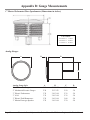
1
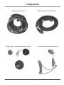
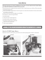
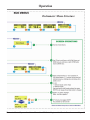
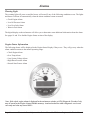
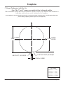
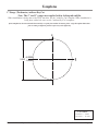
Installation Manual
BY Series Engines
Electronic Control System
Installation Manual
for BY Series Engines
with Classic Controls
MANINBYCM01
Revision 1.0
Notice to Boat Manufacturer, Installer, and Consumer
Throughout this manual, warnings are used to alert the installer/operator to special instructions concerning a
particular service or operation that may be hazardous if performed incorrectly or carelessly. Observe these
alerts carefully!
These “safety alerts” alone cannot eliminate the hazards that they signal. Strict compliance to these special
instructions when performing installation, operation, and maintenance plus “common sense” operation are
the most effective accident prevention measures.
Warning
This device should not be used as a navigational aid to prevent collision, grounding, boat damage, or personal
injury. When the boat is moving, water depth may change too quickly to allow time for you to react. Always
operate the boat at very slow speeds if you suspect shallow water or submerged objects.
Warning
This product contains lead, a chemical known to the State of California to cause cancer, birth defects, and other
reproductive harm.
RECREATIONAL CRAFT DIRECTIVE 94/25/EC
This product has been designed to be compliant with the above Directive.
Maximum performance, and compliance with the EMC Directive, can only be ensured by correct installation.
It is strongly recommended that the installation conforms with the following standards:
APPLICABLE STANDARDS
a) ISO 8846 Small Craft-Electrical Devices
Protection against ignition of surrounding flammable gases.
b) ISO = International Standards Organization
This device meets or exceeds the applicable ABYC, ISO, and USCG safe boating rules, regulations, standards,
and guidelines.
SAFE BOATING ON THE WEB
U.S. Coast Guard
www.uscg.mil
U.S. Power Squadron www.usps.org
NMEA 2000® is a registered trademark of the National Marine Electronics Association.
Disassembly and repair of this electronic unit should only be performed by authorized service personnel. Any
modification of the serial number or attempt to repair the original equipment or accessories by unauthorized
individuals will void the warranty. Handling and/or opening this unit may result in exposure to lead, in the form
of solder.
The information contained in this manual is believed to be accurate at the time of going to print but no responsibility, direct or consequential, can be accepted for
damage resulting from the use of this information. The manufacturers reserve the right to make changes, without notice, to any of its products.
Page Electronic Control System: Installation Manual for BY Series Engines with Classic Controls
Table of Contents
Components . . . . . . . . . . . . . . . . . . . . . . . . . . . . . . . . . . . . . . . . . . . . . . . . . . . . . . . . . . . . . . . . . . . . . . . . . 4
Installation. . . . . . . . . . . . . . . . . . . . . . . . . . . . . . . . . . . . . . . . . . . . . . . . . . . . . . . . . . . . . . . . . . . . . . . . . . . 6
Route the Engine Harness. . . . . . . . . . . . . . . . . . . . . . . . . . . . . . . . . . . . . . . . . . . . . . . . . . . . . . . . . . . . 6
Route the Shift Cable . . . . . . . . . . . . . . . . . . . . . . . . . . . . . . . . . . . . . . . . . . . . . . . . . . . . . . . . . . . . . . . 7
Install Battery Switch and Engine Breaker. . . . . . . . . . . . . . . . . . . . . . . . . . . . . . . . . . . . . . . . . . . . . . . 8
Install the Engine . . . . . . . . . . . . . . . . . . . . . . . . . . . . . . . . . . . . . . . . . . . . . . . . . . . . . . . . . . . . . . . . . . 9
Connect the Items in the Engine Area. . . . . . . . . . . . . . . . . . . . . . . . . . . . . . . . . . . . . . . . . . . . . . . . . . . 9
Install the Shifter. . . . . . . . . . . . . . . . . . . . . . . . . . . . . . . . . . . . . . . . . . . . . . . . . . . . . . . . . . . . . . . . . . 10
Install the Helm Components. . . . . . . . . . . . . . . . . . . . . . . . . . . . . . . . . . . . . . . . . . . . . . . . . . . . . . . . 10
Install the Tachometer. . . . . . . . . . . . . . . . . . . . . . . . . . . . . . . . . . . . . . . . . . . . . . . . . . . . . . . . . . . . . . 11
Check Out and Operation. . . . . . . . . . . . . . . . . . . . . . . . . . . . . . . . . . . . . . . . . . . . . . . . . . . . . . . . . . . . . . 12
Start the Engine. . . . . . . . . . . . . . . . . . . . . . . . . . . . . . . . . . . . . . . . . . . . . . . . . . . . . . . . . . . . . . . . . . . 12
Move the Boat. . . . . . . . . . . . . . . . . . . . . . . . . . . . . . . . . . . . . . . . . . . . . . . . . . . . . . . . . . . . . . . . . . . . 12
Shut Down . . . . . . . . . . . . . . . . . . . . . . . . . . . . . . . . . . . . . . . . . . . . . . . . . . . . . . . . . . . . . . . . . . . . . . 12
Tachometer Display . . . . . . . . . . . . . . . . . . . . . . . . . . . . . . . . . . . . . . . . . . . . . . . . . . . . . . . . . . . . . . . 12
Operation. . . . . . . . . . . . . . . . . . . . . . . . . . . . . . . . . . . . . . . . . . . . . . . . . . . . . . . . . . . . . . . . . . . . . . . . . . . 13
Tachometer Menu Structure. . . . . . . . . . . . . . . . . . . . . . . . . . . . . . . . . . . . . . . . . . . . . . . . . . . . . . . . . 14
Warning Light. . . . . . . . . . . . . . . . . . . . . . . . . . . . . . . . . . . . . . . . . . . . . . . . . . . . . . . . . . . . . . . . . . . . 16
Engine Status Information . . . . . . . . . . . . . . . . . . . . . . . . . . . . . . . . . . . . . . . . . . . . . . . . . . . . . . . . . . 16
Templates . . . . . . . . . . . . . . . . . . . . . . . . . . . . . . . . . . . . . . . . . . . . . . . . . . . . . . . . . . . . . . . . . . . . . . . . . . 17
3” Gauge (Tachometer) with Key Cut . . . . . . . . . . . . . . . . . . . . . . . . . . . . . . . . . . . . . . . . . . . . . . . . . 17
3” Gauge (Tachometer) without Key Cut. . . . . . . . . . . . . . . . . . . . . . . . . . . . . . . . . . . . . . . . . . . . . . . 19
2” Gauge with Key Cut. . . . . . . . . . . . . . . . . . . . . . . . . . . . . . . . . . . . . . . . . . . . . . . . . . . . . . . . . . . . . 21
2” Gauge without Key Cut. . . . . . . . . . . . . . . . . . . . . . . . . . . . . . . . . . . . . . . . . . . . . . . . . . . . . . . . . . 21
CH18000 Top Mount . . . . . . . . . . . . . . . . . . . . . . . . . . . . . . . . . . . . . . . . . . . . . . . . . . . . . . . . . . . . . . 23
CH18000 Side Mount. . . . . . . . . . . . . . . . . . . . . . . . . . . . . . . . . . . . . . . . . . . . . . . . . . . . . . . . . . . . . . 25
Key Switch Panel - CP19400. . . . . . . . . . . . . . . . . . . . . . . . . . . . . . . . . . . . . . . . . . . . . . . . . . . . . . . . 27
Appendix A: Analog Gauges . . . . . . . . . . . . . . . . . . . . . . . . . . . . . . . . . . . . . . . . . . . . . . . . . . . . . . . . . . . 29
Appendix B: Gauge Measurements . . . . . . . . . . . . . . . . . . . . . . . . . . . . . . . . . . . . . . . . . . . . . . . . . . . . . . 30
Electronic Control System: Installation Manual for BY Series Engines with Classic Controls Page Components
Please familiarize yourself with the following components:
CH18000 Series
Side Mount Control
CH18000 Series
Top Mount Control
Tachometer
Ignition Switch
with Digital Display
Page Electronic Control System: Installation Manual for BY Series Engines with Classic Controls
Components
CE500xx Engine Harness
Warning Light / Audible Alarm/Cut-off Switch
CE503xx Engine Extension Harness
Cut-off Switch with Lanyard attached
Electronic Control System: Installation Manual for BY Series Engines with Classic Controls Page Installation
This book represents a stern drive installation, because there are more items involved to install. Marine
gear (inboard) installations are similar but have less parts.
The tasks that must be completed to hook up the BY Classic Control Systems are as follows (This section takes
you through each task area).
• Route the CE500XX engine harness from the engine area to the helm and install and connect the items that
are attached to the transom.
• Route the shift cable from the engine area to the helm.
• Install battery switch and engine breaker.
• Install the engine.
• Connect the items in the engine area.
• Install the shifter and the tachometer.
• Install the remaining helm components.
• Connect the items at the helm.
• Check out the installation.
Warning: Make all connections in accordance with applicable codes and standards.
Route the CE500XX Engine Harness
Mount the stern drive transom plate, gear lube reservoir, and trim pump per the stern drive instructions. Gear Oil
Page Trim Pump
Electronic Control System: Installation Manual for BY Series Engines with Classic Controls
Installation
Run the engine harness from the helm to the transom area. The engine harness has three main connection
points, the helm, the transom and the engine.
CE500xx Helm End
CE500xx Transom Breakout
CE500xx to Engine
Attach the transom breakout point to the transom near the centerline of the engine and high enough that you can
access this point after the installation is complete. Make the following connections and dress the wires.
• Gear Oil Return (Black) and Gear Oil (Brown) connect to the Gear Oil Reservoir. Tie back when using
Marine Gear.
• Trim Position Return (Black) and Drive Trim Position (Dark Blue) connect to wires from the transom plate.
Tie back when using Marine Gear.
• Fuel Return (Black) and Fuel (Pink) go to the fuel sender.
• Tie the J7 NMEA connector back at this time. This connector is supplied for future NMEA 2000 connections.
Leave the helm end and the engine end disconnected at this time.
Route the Shift Cable
Mount the shift plate that came with the stern drive near the stern drive transom plate and route the shift cable from
this area to the helm where the control will be mounted. Connect the stern drive lower leg cable and the cable that
goes to the shift control. The upper cable goes to the helm and the lower cable goes to the stern drive. Shift Plate
Electronic Control System: Installation Manual for BY Series Engines with Classic Controls Page Installation
Install Battery Switch and Engine Breaker
Install the battery switch and close to the battery switch install an 80 amp circuit breaker. The circuit breaker
will need to be located so the 2.5 meter (8 foot) cable supplied on the engine can reach the breaker. Do not
extend this cable.
The wire from the battery switch to the circuit breaker should not be longer than one meter (3 feet). The wire
size should be 10mm2 (AWG 6).
The wire size of the main ground cable and the cable to the starter motor should be sized based on their length.
When determining the wire size add the length of the negative cable from the engine block to the battery and the
length of the positive cable from the starter to the battery together.
Distance
Wire size
Less than 5 meters (16 feet)
20mm2
AWG 4
Less than 9 meters (30 feet)
40mm2
AWG 1
Breaker Wiring Diagram
Page Electronic Control System: Installation Manual for BY Series Engines with Classic Controls
Installation
Install the Engine
Install and align the engine per the instructions that come with the engine and the stern drive.
Connect the Items in the Engine Area
Route the CE500XX engine harness from the center of the transom to the top connector of the engine computer
box located on the starboard side of the engine. Route the power cable from the engine to the 80 amp engine
breaker installed earlier. Connect the ground to the common block and complete the connections per the diagram
on page 8.
Engine Harness Connection
Engine Electronics Connection
Electronic Control System: Installation Manual for BY Series Engines with Classic Controls Page Installation
Install the Shifter
Use the template supplied with the shifter or pages 23 and 24 of this manual to cut out the opening for the control
head. Mount the shifter and connect the shift cable to the control head per the Control Instruction Manual.
CH18000 Series Side Mount
CH18000 Series Side Mount
front view
rear view
shown with shift control cable
J64 and J6B
connectors
Trailer Harness
Trim Harness
CH18000 Series Top Mount
CH18000 Series Top Mount
front view
rear view
shown with shift control cable
J64 and J6B
connectors
Connect the CE500XX cable that was route to the helm earlier. The J6A and the J6B connectors mate with
the connectors on the control. Connect the trim harness supplied with the stern drive to the three bullet
connectors.
Page 10
Electronic Control System: Installation Manual for BY Series Engines with Classic Controls
Installation
Install the Helm Components
The following items are supplied as part of kit CP19400K. Locate an appropriate place and mount each item
near the helm. The audible alarm should be mounted behind the helm so it is out of the weather.
• Key Switch • Lanyard Switch
• Indicator LED
• Audible Alarm
Indicator LED
Key Switch
Cut-off Switch
(front and back)
(front and back)
Audible Alarm
(front and back)
Lanyard on
Cut-off Switch
When the parts are mounted connect the items to the CE500XX cable as shown in the diagram.
Install the Tachometer
Back of Tachometer
Mount the Tachometer using the cut out template on page 17 or 19 to insert the
connector marked J3 tachometer on the CE500XX engine cable. If no other gauges
are being used, individually tape back the other wires in the CE500XX harness for
future use.
If optional gauges are being installed see Appendix B of this manual.
Electronic Control System: Installation Manual for BY Series Engines with Classic Controls Page 11
Checkout and Operation
For complete operating instructions see the Operators Manual, part number MANOPBYCM01.
WARNING
The boat will start to move during the next steps.
Be very cautious when first engaging the gears to establish that forward is truly forward
and reverse is truly reverse. A quick in-and-out of gear test is recommended.
Ensure that the boat is clear of all obstacles forward and aft before conducting this test.
Start the Engine
• Connect the safety lanyard to your person.
• Move the control handle to the NEUTRAL position.
• Turn the key switch to the ON position.
• Turn and hold the key switch at the START position until engine starts.
• When the engine is running allow the key switch to return to the ON position.
The tachometer will indicate the idle RPM’s and the boat is ready to operate.
Moving the Boat
Move the control lever from NEUTRAL to a GEAR position. On Side Mount controls it will be necessary to
press the Neutral Interlock button. The boat will move. Pushing the handle past the gear detent will advance
the throttle.
Always operate the boat in a safe manner.
Shut Down
When ready to shut down the engine return the control to NEUTRAL and turn the Key Switch to the OFF
position. This will stop the engine.
Tachometer Display
The digital display on the tachometer shows a variety of engine data. The operation of the display is shown on
the next pages. All of the items listed here may be seen on the tachometer’s digital display.
Data
RPM
Battery Voltage
Coolant Temperature
Boost Pressure
Engine Load
Fuel Rate
Engine Hours
* Fuel Level
* Oil Pressure
Alarms
Check Engine Alarm
Over Temp Alarm
Low System Voltage Alarm
High Boost Pressure Alarm
Throttle Position Sensor Alarm
Neutral Start Protect Alarm
* No digital value will be displayed for these parameters on Classic Systems.
Page 12
Electronic Control System: Installation Manual for BY Series Engines with Classic Controls
Operation
Tachometer Menu Structure
The tachometer menu structure (please refer to detailed diagram on the next two pages) is set up with a Main
Menu display, accompanied by their respective submenus. Successfully navigating the main and submenus
depends on the familiarization and understanding of how the Enter, Up, and Down buttons are pressed, and
in what combination.
To Navigate the Menus:
• After the “Yanmar Marine Power-on” flashes on, the screen will return to the last
display viewed on shutdown. Use the up and down buttons to scroll through the
Main Menu items from ENGINE DATA to SYSTEM SETUP.
V1.8
• To view the submenu features under one of these Main Menu displays, press the
enter button. Then use the up button to move forward and the DOWN button to
move backward through the submenus.
• Pressing the UP button at the end of the submenu scrolls directly to the first
submenu item.
• At any time you may return to the Main Menu by pressing the enter button.
• With a bit of practice, navigating the menu should become second nature.
To Customize the Main Menu:
It is possible to customize the Main Menu to better suit your boating needs.
• Scroll through the submenu until the substitute item is found. Press and hold the
enter button for 3 seconds. The item will be “recognized” as the new choice for
the Main Menu display. You will be returned to the Main Menu with the new item
displayed and the previous Main Menu item will become part of the submenu.
CONTROL BUTTON OPERATION
To Enter or Exit a submenu
• Press enter button at any Main Menu display to go into submenus.
• Press ENTER button at any time to exit back to the Main Menu.
TO customize THE MAIN MENU
• Choose submenu item to replace Main Menu item, then Press and Hold enter button for 3 seconds.
This will return you to the Main Menu, replacing the previous item with the one you just chose.
backlight
• Press the up/down buttons at same time (ONLY possible when in Main Menu).
Electronic Control System: Installation Manual for BY Series Engines with Classic Controls Page 13
Operation
Page 14
Electronic Control System: Installation Manual for BY Series Engines with Classic Controls
Operation
Tachometer Menu Structure
Electronic Control System: Installation Manual for BY Series Engines with Classic Controls Page 15
Alarms
Warning Light
The warning light will come on and the buzzer will sound if any of the following conditions occur. The lights
and buzzer will turn off automatically when the alarm condition returns to normal.
• Check Engine Alarm
• Low Oil Pressure Alarm
• Low Gear Lube Alarm
• Water in Fuel Alarm
The digital display on the tachometer will allow you to determine some additional information about the alarm.
See pages 14 and 15 to find the Engine Status section of the display.
Engine Status Information
The following alarms will be displayed in the Engine Status Display if they occur. They will go away when the
alarm condition returns to the normal operating range.
• Check Engine Alarm
• Over Temp Alarm
• Low System Voltage Alarm
• High Boost Pressure Alarm
• Neutral Start Protect Alarm
Note: If the check engine alarm is displayed in the tachometer window, a DTC (Siagnostic Trouske Code)
may be stored in the Engine Control Module memory. A trained technician with a diagnostic service tool
can ready and clear any stored DTCs.
Page 16
Electronic Control System: Installation Manual for BY Series Engines with Classic Controls
Templates
3” Gauge (Tachometer) with Key Cut
Note: The 2" and 3" gauges are supplied with a locking tab and flat.
When installation is being done with a CNC machine, use the "with Key Cut" template. When installation is
being done with a hole saw, use the "without Key Cut" templates.
If this template has been downloaded electronically or copied from another document, please verify all template dimensions
prior to cutting as different printers/copiers may scale differently.
RECOMMENDED
PANEL CUTOUT w/KEY CUT
3.470
+0.0200
3.340
-0.0000
+0.0000
-0.0200
KEY SLOT, AS REQ’D
FLAT CUT-OUT, AS REQ’D
0.160 ± 0.0050
U.S. to Metric
0.005 inches = 0.1mm
0.02 inches = 0.5mm
0.16 inches =4.1mm
3.34 inches = 84.8mm
3.47 inches = 88.1mm
Electronic Control System: Installation Manual for BY Series Engines with Classic Controls Page 17
Templates
This page left intentionally blank.
Page 18
Electronic Control System: Installation Manual for BY Series Engines with Classic Controls
Templates
3” Gauge (Tachometer) without Key Cut
Note: The 2" and 3" gauges are supplied with a locking tab and flat.
When installation is being done with a CNC machine, use the "with Key Cut" template. When installation is
being done with a hole saw, use the "without Key Cut" templates.
If this template has been downloaded electronically or copied from another document, please verify all template dimensions
prior to cutting as different printers/copiers may scale differently.
PANEL CUTOUT
w/out KEY CUT
3.415
+0.0000
-0.0200
U.S. to Metric
0.02 inches = 0.5mm
3.415 inches =86.7mm
Electronic Control System: Installation Manual for BY Series Engines with Classic Controls Page 19
Templates
This page left intentionally blank.
Page 20
Electronic Control System: Installation Manual for BY Series Engines with Classic Controls
Templates
2” Gauge with Key Cut
Note: The 2" and 3" gauges are supplied with a locking tab and flat.
When installation is being done with a CNC machine, use the "with Key Cut" template. When installation is
being done with a hole saw, use the "without Key Cut" templates.
If this template has been downloaded electronically or copied from another document, please verify all template dimensions
prior to cutting as different printers/copiers may scale differently.
RECOMMENDED
PANEL CUTOUT w/KEY CUT
2.100
+0.0000
-0.0200
1.970
KEY SLOT, AS REQ’D
+0.0200
-0.0000
FLAT CUT-OUT, AS REQ’D
0.156 ± 0.0050
2” Gauge without Key Cut
PANEL CUTOUT
w/out KEY CUT
+0.0000
2.050
-0.0200
U.S. to Metric
0.005 inches
0.02 inches
0.156 inches
1.97 inches
2.05 inches
2.1 inches
Electronic Control System: Installation Manual for BY Series Engines with Classic Controls = 0.1mm
= 0.5mm
= 4.0mm
=50.0mm
=52.1mm
= 53.3mm
Page 21
Templates
This page left intentionally blank.
Page 22
Electronic Control System: Installation Manual for BY Series Engines with Classic Controls
Templates
CH18000 Top Mount Template
If this template has been downloaded electronically or copied from another document, please verify all template dimensions
prior to cutting as different printers/copiers may scale differently.
Diameter 7/32"
(5.6 mm)
1/2"
(12.7 mm)
R 1/4"
(6.4 mm)
R 3/16"
(4.8 mm)
3/8"
(9.5 mm)
5 3/16"
(131.8 mm)
5"
(127.0 mm)
4 3/16"
(106.4 mm)
2 1/2"
(63.5 mm)
3/32"
(2.4 mm)
Electronic Control System: Installation Manual for BY Series Engines with Classic Controls Page 23
Templates
This page left intentionally blank.
Page 24
Electronic Control System: Installation Manual for BY Series Engines with Classic Controls
Templates
CH1700 Side Mount Template
If this template has been downloaded electronically or copied from another document, please verify all template dimensions
prior to cutting as different printers/copiers may scale differently.
Electronic Control System: Installation Manual for BY Series Engines with Classic Controls Page 25
Templates
This page left intentionally blank.
Page 26
Electronic Control System: Installation Manual for BY Series Engines with Classic Controls
Templates
Key Switch Panel - CP19400
If this template has been downloaded electronically or copied from another document, please verify all template dimensions prior
to cutting as different printers/copiers may scale differently.
U.S. to Metric
3/16 inches = 4.76 mm
7/16 inches = 11.11 mm
1/2 inches = 12.7 mm
11/16 inches = 17.46 mm
13/16 inches = 20.64 mm
7/8 inches = 22.2 mm
15/16 inches = 23.81 mm
1 5/32 inches = 25.56 mm
1 7/16 inches = 36.51mm
1 7/8 inches = 47.63 mm
2 13/32 inches =51.21 mm
3 3/8 inches = 85.73 mm
Electronic Control System: Installation Manual for BY Series Engines with Classic Controls Page 27
Templates
This page left intentionally blank.
Page 28
Electronic Control System: Installation Manual for BY Series Engines with Classic Controls
Appendix A: Analog Gauges
Several options are available for the Classic Control System.
Analog Gauges
The following gauges are available for easy connection to the system. The wires are in the main harness and
are located behind the helm.
Speedometer - This 3 inch gauge requires a pitot tube connection.
Trim, Fuel Level, Oil Pressure and Volt gauges are also available.
Electronic Control System: Installation Manual for BY Series Engines with Classic Controls Page 29
Appendix B: Gauge Measurements
3” Master Tachometer/Slave Speedometer (Dimensions in inches)
U.S. to Metric
0.54 inches = 13.7mm
2.579 inches = 65.5mm
3.79 inches = 96.3mm
Analog Gauges
A
D
B
C
Analog Gauge Style
A
B
C
2” All Electrical Gauges2.382.13/2.222.50
2” Mechanical Pressure Gauges2.382.13.2.222.50
3” Electric Tachometers3.783.41/3.442.76
3” 4-N-13.783.41/3.442.76
3” Electric Tach/Hourmeters
3.78
3.41/3.44
3.88
3” Marine Pitot-type Speedos
3.78
3.41/3.44
2.70
Page 30
D
.38
.38
.58
.58
.58
.58
Electronic Control System: Installation Manual for BY Series Engines with Classic Controls
Electronic Control System: Installation Manual for BY Series Engines with Classic Controls Page 31
Page 32
Electronic Control System: Installation Manual for BY Series Engines with Classic Controls