1
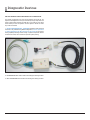
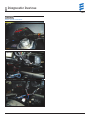
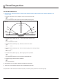
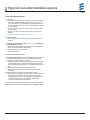
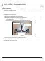
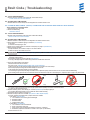
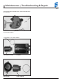
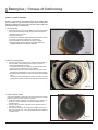
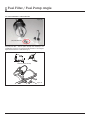
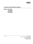
H YDRONI C D5S/SC
D IAG NOSTIC AND REPAIR MANU A L
A WORLD OF COMFORT
Table of Contents
REVISION LEVEL A - 12/09/13
Chapter
1
2
3
4
5
6
7
8
9
Content
Page
System Overview . . . . . . . . . . . . . . . . . . . . . . . . . . . . . . . . . . . . . . . . . . . . . . . . . . . . . . . . . . . . . . . . . . . . . . . . . . . . . . . . . . . . . . . . . . . . . . . . 3
Diagnostic Devices . . . . . . . . . . . . . . . . . . . . . . . . . . . . . . . . . . . . . . . . . . . . . . . . . . . . . . . . . . . . . . . . . . . . . . . . . . . . . . . . . . . . . . . . . . . . . . 4
Visual Inspection . . . . . . . . . . . . . . . . . . . . . . . . . . . . . . . . . . . . . . . . . . . . . . . . . . . . . . . . . . . . . . . . . . . . . . . . . . . . . . . . . . . . . . . . . . . . . . . . 6
Typical non-warranty repairs . . . . . . . . . . . . . . . . . . . . . . . . . . . . . . . . . . . . . . . . . . . . . . . . . . . . . . . . . . . . . . . . . . . . . . . . . . . . . . . . . . . . . . . 7
Fault Codes / Troubleshooting . . . . . . . . . . . . . . . . . . . . . . . . . . . . . . . . . . . . . . . . . . . . . . . . . . . . . . . . . . . . . . . . . . . . . . . . . . . . . . . . . . . . . . 8
Maintenance / Troubleshooting / Repair . . . . . . . . . . . . . . . . . . . . . . . . . . . . . . . . . . . . . . . . . . . . . . . . . . . . . . . . . . . . . . . . . . . . . . . . . . . . . 12
Examples / Causes of carboning . . . . . . . . . . . . . . . . . . . . . . . . . . . . . . . . . . . . . . . . . . . . . . . . . . . . . . . . . . . . . . . . . . . . . . . . . . . . . . . . . . . 14
Wiring Diagrams . . . . . . . . . . . . . . . . . . . . . . . . . . . . . . . . . . . . . . . . . . . . . . . . . . . . . . . . . . . . . . . . . . . . . . . . . . . . . . . . . . . . . . . . . . . . . . . . 18
Fuel Filter / Fuel Pump Angle . . . . . . . . . . . . . . . . . . . . . . . . . . . . . . . . . . . . . . . . . . . . . . . . . . . . . . . . . . . . . . . . . . . . . . . . . . . . . . . . . . . . . . 21
PLEASE NOTE! The EW14 Warranty Process requires Edith extraction printouts to record codes before proceeding with repairs – and after the repair
steps listed in this manual are completed . For your warranty claim to be paid you must document the Complaint, Cause and Correction steps in your
warranty claim write-up .
CAUTION: Indicates that personal injury or damage to equipment may occur unless specific guidelines are followed.
DANGER: Indicates that serious or fatal injury may result if specific guidelines are not followed.
This document aims to support service technicians and end users in North America. This does not replace documentation produced by J. Eberspächer.
The installation instructions and standards described in this document are NOT APPLICABLE TO MARINE INSTALLATIONS.
Please consult a certified Espar Marine dealer for marine installation.
This publication was correct at the time of going to print. However, Espar Inc. has a policy of continuous improvement and reserves the right to amend any
specifications without prior notice.
2
1 System Overview
REVISION LEVEL A - 12/09/13
SYSTEM OVERVIEW
The Espar Hydronic D5 heater is designed to lower idling by providing an
alternative for engine pre-heat and or cab heat. The Espar Hydronic D5 is also
designed to maintain engine temperature and or cabin temperature. In the
instance cabin temperature is to be maintained, precondition the cab to the
desired temperature is recommended.
SYSTEM OPERATION
1. The operator turns on the device via either an OEM operating control panel,
third party controller, Espar on/off button, switch or an Espar timer to control
the designated start time. The key factor of the control is the fact it sends
power to the heater on the yellow (signal wire).
a. PLEASE NOTE! In the case the heater does not operate (no fan or
circulating pump), verifying there is output on the yellow wire is imperative.
This can be done by inserting an adapter in the harness (page 6) at the
heater and using a DVM to validate power on the yellow. This should be
close to battery voltage. If there is battery voltage found connect diagnostic device (page 4-5) and confirm fault code.
2. The controls options are too many to be listed in this manual but can be
found on the Espar web site, www.espar.com or in your OEM operator’s
manual.
3. When the heater is started the following events take place:
a. The unit runs through a 3 second diagnostic check.
b. The fan, coolant circulating pump and glow pin come on.
c. After 60 seconds the fuel pump starts pumping fuel.
d. If the unit doesn’t fire within 2 minutes:
i. The unit will cut the fuel pump and pause for 30 seconds.
ii. The unit will attempt a second start.
e. If the unit doesn’t fire within 2 minutes of the restart attempt a code 52
will be set (see code descriptions).
PLEASE NOTE!
Times are approximate, it is more important to understand there are 2
attempts and the process can takes some time. The unit must be allowed
time to run through its cycle. If there is an issue it will trip a code.
4. Inside the unit
a. The fan provide air flow through the combustion chamber and the
starting air hole
b. The glow pin heats the atomizer chamber in preparation for fuel.
c. Fuel first enters the atomizer hole.
d. It is then atomized and ignites.
e. The flame burns through the combustion chamber.
f. The flame detector recognizes a temperature rise and cuts operation of
the glow pin.
g. The control unit measures the input and output coolant temperature via
a coolant temperature sensors inserted in the coolant flow of the water
jacket.
This is important to know because the heater can monitor the temperature difference to validate proper coolant flow. In the case of overheat
codes refer to the appropriate codes.
h. The unit switches between full load, part load and standby automatically
given the coolant temperatures.
i. When it first ignites it is always in boost.
ii. Mode is controlled via fuel pump frequency and fan speed.
5. Difference in modes
a. When operating in full load the heater will operate at 17,100 BTU to
bring the temperature up. Once the temperature is met it cycles to part
load at 8,200 BTU.
b. If the heater meets 176 F it will cycle to standby mode and extinguish
the flame. The circulating pump will continue to operate so the heater
can monitor and maintain the complete system.
c. If the coolant temperature drops to 167 F the heater will make a repeat
start and repeat the previous steps until it is turned off or faults out.
d. If the heater is completely turned off including the circulating pump and
there is a verified good switch signal then reference the troubleshooting
section of the manual.
PLEASE NOTE!
After ten no-start attempts the Hydronic 5 ECU will lock to prevent further
startup actions. Until it is verified the ECU is not locked, no repairs should be
attempted on the heater. Because of this, having the proper diagnostic tooling
is a requirement for performing Hydronic 5 repairs.
Figure 5
3
2 Diagnostic Devices
REVISION LEVEL A - 12/09/13
MULTIPLE DIAGNOSTIC DEVICES ARE AVAILABLE AS OUTLINED BELOW:
This manual is designed to be used with the Hydronic D5 S and SC. The
Hydronic II D5E diagnostics can only be accessed by using an Easy Start fault
reader or Edith. Please reference the data tag on your heater to verify which
heater model you have. The Hydronic I D5 S or Hydronic I D5 SC can utilize
any of the fault readers.
1. EDITH PC BASED DIAGNOSTICS – PREFERRED: The ability to print out an ECU
extraction is only available using EDITH PC diagnostics, and is a requirement
for taking advantage of the EW14 express warranty protocols. Full product
testing capability including remote running of system components without
removal of the heater, can be utilized for rapid fuel system priming.
EDITH
Figure 1
2. DIGI-DIAGNOSTIC TOOL: Used for basic code viewing and clearing functions.
3. FAULT CODE READER: Used for basic code viewing and clearing functions.
4
2 Diagnostic Devices
REVISION LEVEL A - 12/09/13
EDITH PC DIAGNOSTICS (PREFERENCE)
Figure 2
5
2 Diagnostic Devices
REVISION LEVEL A - 12/09/13
2 . DIGI-DIAGNOSTIC TOOL / FAULT CODE READER
Both of these units will provide quick access to the checking and clearing
of fault codes but only Edith will provide true diagnostics capability. As such
these units are shown for reference only.
Figure 3
SPECIAL TOOLS AND ADAPTORS
1. Depending on the heater model and application, diagnostic adapters
may be required to interface with the heater harness and perform
functions.
2. PLEASE NOTE!
If the heater does not operate (no fan or circulating pump), verifying
there is output on the yellow wire is imperative. This can be done by
inserting the proper following adapter in the harness at the heater and
using a DVM to validate power on the yellow when the control device is
requesting heat. This should be close to battery voltage. If there is battery
voltage found connect diagnostic device (figure 3) and confirm fault
code.
6
Figure 4
Figure 5
Standard, MaxxPower and ParkSmart Gen 5 Espar diagnostic interface
adapter. Part number: 20 2900 70 50 28
ParkSmart Gen 1,2 & 3 Espar diagnostic interface adapter.
Part number: 25 2786 07 00 01
2 Diagnostic Devices
REVISION LEVEL A - 12/09/13
PLEASE NOTE!
Adapter connection on Park Smart.
Figure 6
Figure 7
Figure 8
7
3 Visual Inspection
REVISION LEVEL A - 12/09/13
THE 60 SECOND VISUAL INSPECTION
1. Before starting any repairs always perform a complete a visual installation inspection. Problems resulting from an improper installation are not
warrantable issues:
a. Fuel Pump angle: Between 15 and 35 degrees- Inlet is low side, outlet is high side.
i. Yes
______
ii. No
______
iii.If not it will need to be reset to proper angle before completing repairs (pg. 26)
Figure 9
Permissible
pref
erab
le
erab
le
pref
not permissible
not permissible
Fuel Metering Pump
b. Combustion Exhaust (flexible pipe only) - 1.5 to 2.5 inch extension past rear of cab?
i. Yes
_____
ii. No
_____
iii.If not it will need to be rerouted.
c. Combustion Exhaust (Flexible pipe only) - No kinks, not unwound or crushed.
i. Yes
_____
ii. No
_____
d. Combustion Exhaust (Flexible pipe only) - Bent at the end facing the ground at a 45 degree angle?
i. Yes
_____
ii. No
_____
iii.If no readjust.
e. Combustion exhaust (flexible pipe only) - No low hanging areas to trap moisture.
i. Yes
_____
ii. No
_____
iii.If not eliminate the droop or drill 1/8 th inch hole for condensation drain.
f. Coolant lines free of obstruction, kinks or damaged?
i. Yes
_____
ii. No
_____
iii.If no repair as needed.
2. Verify operation; if unit runs properly complete the job otherwise continue below.
3. Turn the unit on, check diagnostic codes and utilize the troubleshooting steps listed.
The Hydronic SC can have either internal or external fuel pumps - the internal pump is preset to the correct mounting angle.
8
4 Typical non-warrantable repairs
REVISION LEVEL A - 12/09/13
TYPICAL NON-WARANTABLE REPAIRS:
1. FUEL FILTER
a. The fuel filter can be found on the inlet side of the fuel pump, see page 24.
If this filter is plugged or partially plugged it can cause a no-start to
your heater. The filter can be serviced by using a backing wrench and
turning the inlet cap off the pump. Then use a small pick to pull the filter
out to be replaced.
b. This filter may cause the heater to smoke during start-up and smoke
during operation.
c. This filter can cause your heater to over fuel due to repetitive start
attempts.
d. Common codes associated with a fuel filter: 50 – 56.
2. ATOMIZER SCREEN
a. This screen is found in the heater after the ceramic igniter has been
removed. .
3. OVERHEAT AND ASSOCIATED FAILURES (CODE 12,14 &15) ARE NORMALLY
NON-WARRANTABLE FAILURES
a. Heater coolant pump plugged from system debris or casting material.
i. Clean and reseal if possible or replace pump.
b. Poor coolant flow from a system issue.
c. Airlock in water jacket.
4. PLUGGED INTAKE AND/OR EXHAUST
5. CARBONED BUNER CHAMBER – these are non-warrantable unless caused
by a primary failed part covered under a warrantable failure situation:
a. Caused by a restriction of intake or exhaust.
b. Caused by improper angle of fuel pump, pump must be 15 – 35 degree
angle up with the outlet / harness connection being on the high side.
c. Fuel system that has had improper amount of additives injected into the
tank.
d. Fuel system with any kind of oil being used in the fuel.
e. Short cycling caused by improper application or electrical power
connections.
6. Modified parts during removal or repair while under warranty
a. Any place where the integrity of the part has been compromised during
the repair will not be covered under warranty. If any part must be
modified to remove or service - the Espar Warranty Department must
be called first and a WA # must be obtained. 1-800-387-4800
1. Cut wires, broken housings, damaged parts
If a harness or a connector must be repaired in any way the Espar Warranty
Department must be contacted and a WA# first obtained. 1-800-387-4800
9
5 Fault Code / Troubleshooting
REVISION LEVEL A - 12/09/13
IF THERE IS NO COMMUNICATION
Fault reader displaying - - - (dash dash dash) or non-functional Espar unit without fault codes
1. Check units open circuit voltage at the batteries.
2. If the voltage is below 12.6 (Flooded cell) or below 12.8 (AGM) charge the batteries following your company’s standard practices and restart troubleshooting.
a. Otherwise continue below.
3. Connect Diagnostic Interface adapter (Figure 10).
4. Using the adapter and multi-meter:
a. Perform a continuity test to verify ground on the brown wire of 0 ohms.
b. Perform a voltage test to verify battery power between the red wire and the brown wire.
I. If voltage is below 10.5 volts troubleshoot the tractor’s wiring utilizing the manufacturer’s documentation.
c. Perform a test to verify continuity to the diagnostic reader at blue wire-white tracer at the white connector and blue wire-yellow tracer on the Espar heater.
I. If wires are damaged repair wires.
II. Always use heat shrink, solder or connectors with heat shrink tubing when making wiring repairs.
White diagnostic plug
Connection to the heater
side of the harness
Connection to the truck
side of the harness
Figure 10
5. If the problem persists connect the test harness and wire the Espar directly to the batteries.
a. Plug the 8 pin adapter test harness in series with the Espar harness at the heater.
6. Use a known good battery (12 volt min.) and supply external power using the white connector plug (heavy red wire=power, heavy brown wire=ground).
7. If the problem persists, replace the control unit (ECU).
10
5 Fault Code / Troubleshooting
REVISION LEVEL A - 12/09/13
FAULT CODE / TROUBLESHOOTING
PLEASE NOTE!
Warranty Process - perform an Edith extraction printout to record codes before proceeding. Carefully document the Complaint – Cause and Correction.
000 - NORMAL OPERATION
1. No Repairs needed.
010 – OVER-VOLTAGE
1. System maximum voltage is 16 volts.
2. The only possible cause of this code is either.
a. A battery charger in boost mode.
b. Alternator overcharging.
3. Clear the code repair as needed.
011 - UNDER VOLTAGE SHUT DOWN
1. System minimum voltage is 10.5 volts.
2. Verify battery voltage.
3. Install the Y interface adapter.
4. Connect the multi-meter to the red and brown wires and set to volts DC.
5. Record the voltage.
6. If the voltage is less than 12.6 (flooded cell) 12.8 (AGM) connect the battery charger and log off the job until the batteries are fully charged, otherwise
continue below.
7. Turn on the unit while watching the multi-meter.
8. If the voltage remains above 10.5 clear the code, no repairs are needed, otherwise continue below.
9. Troubleshoot the tractors wiring harness utilizing the factory manuals - check for voltage drop on cables leading to the heater.
10. Clear codes when repaired.
012 - OVERHEAT AT OVERHEATING SENSOR
1. Sensor has detected excessive temperatures.
2. Verify coolant in the system and bleed if necessary.
3. Check coolant hoses to ensuring they are free from obstructions.
4. If equipped with heater shutoff valves, make sure they are open to allow coolant flow.
5. Listen to see if the coolant pump is operating.
i. If the coolant pump is not operating and you are getting a code 12 the internal magnetic coolant pump is plugged. The pump must be removed and cleaned.
(see page 17).
PLEASE NOTE!
This is a non-warranty repair.
PLEASE NOTE!
Care must be taken when removing the lines. The inlet/outlet ports on the pump housing can be damaged or broken if this care is not taken!
6. When removing the control unit inspect the main connector for corrosion.
If the wiring is damaged or connection is corroded, replace the connection and inspect the control unit terminals.
7. Clear code and run unit.
8. If code returns replace the overheat sensor.
9. Clear code and run unit ensuring issue is resolved.
014 - TEMPERATURE DIFFERENCE BETWEEN TEMPERATURE SENSOR AND OVERHEAT SENSOR TO LARGE
1. Check for restricted coolant flow.
i. Large temperature differences between the inlet and outlet lines is an indication of a flow issue.
ii. If equipped with heater shutoff valves, make sure they are open to allow coolant flow.
2. Ensure fuel pump angle is at 15 to 35 degree with the outlet/harness being the high side.
3. Perform a fuel quantity test.
i. Disconnect the fuel line from heater.
ii. Turn the unit on (remember 60 second delay prior to activation).
iii. Place fuel line in graduated cylinder and allow to run for the first of the two start attempt.
iv. Fuel quantity should measure between 8.5 and 9.5 ml.
1. If quantity is low verify the fuel system does not have any obstructions.
2. Replace FMP inlet fuel filter and retest.
3. If quantity is high, replace pump and retest unit.
11
5 Fault Code / Troubleshooting
REVISION LEVEL A - 12/09/13
4. Check for debris in heat exchanger and coolant pump.
i. Listen to see if coolant pump is operating. If pump is not operating and the existing fault is for overheat, the likely issue is a plugged coolant pump.
1. Remove the magnet from pump (found on page 17) and clean. If magnet is plugged the coolant system must be flushed because it is contaminated.
Failure to do this will cause another plugged magnet and could lead to premature engine damage or failure.
5. Inspect the temperature and overheat sensors for corrosion at the terminal.
i. If corrosion is found, validate the cause. If there is coolant found in the connection replace the sensors.
6. If electrical connections are found good check sensors using the resistance chart found on page 19.
015 - OVERHEAT WITH EXCESSIVE TEMPERATURES
1. Sensor has detected excessive temperatures repeatedly.
a. This code indicates the heater has overheated 3 consecutive times.
2. Unlock control unit:
a. Document all codes.
b. Clear codes.
3. Follow procedures outlined for Code 12 and 14.
4. Run unit to ensure the issue is resolved.
017 - OVERHEAT WITH EXCESSIVE TEMPERATURE
1. This code is set when excess temperature (above 130 C) is seen at the overheat sensor
2. See code 015
020 - OPEN CIRCUIT - GLOW PIN (BE CAREFUL NOT TO PULL WIRES OFF GLOW PIN DURING REMOVAL)
1. Inspect glow pin leads for continuity, replace if necessary
2. Check for corrosion in terminals (maintenance)
021 - SHORT CIRCUIT - GLOW PIN (BE CAREFUL NOT TO PULL WIRES OFF GLOW PIN DURING REMOVAL)
1. Inspect glow pin leads for continuity, replace if necessary
2. Check for corrosion in terminals (maintenance)
030 - COMBUSTION AIR FAN (A FAN WITH RUB MARKS IS A NON-WARRANTY FAILURE)
1. Blower fan may be jammed, frozen or plugged
i. Clean if possible and retry fan
2. Replace as necessary
031 - BLOWER MOTOR INTERRUPTED
1. Inspect electrical connections for corrosion (maintenance)
2. Replace fan as necessary
032 - BLOWER MOTOR SHORT CIRCUIT
1. Inspect electrical connections for corrosion (maintenance)
2. Replace fan as necessary
041 - COOLANT PUMP OPEN CIRCUIT - NOTE: A DAMAGED/BROKEN COOLANT PUMP IS NOT WARRANTY
1. Inspect electrical connections for continuity and corrosion (maintenance)
2. Replace as necessary
042 - COOLANT PUMP SHORT - CIRCUIT
1. Inspect electrical connections for continuity and corrosion (maintenance)
2. Replace as necessary.
047 - SHORT CIRCUIT OR OVERLOAD - FUEL METERING PUMP (FMP)
1. Fuel pump positive wire (green w/red) is shorted to chassis ground
2. Unplug the fuel pump and power up unit
3. If fault Code 48 is displayed the fuel pump is defective
4. If fault Code 48 is not displayed recheck wiring
048 - OPEN CIRCUIT - FUEL METERING PUMP (FMP)
Disconnect connector from fuel pump and measure resistance value of fuel pump see values, page 19. If resistance values are O.K., then reconnect
cable harness to the fuel pump.
1. Check fuel pump electrical connector.
a. Pins of female plug end can become spread
b. Re-crimp if needed
c. Clear code and run unit.
d. If problem persists continue below
2. Inspect the wiring for damage, check continuity from the 8 pin housing for an external FMP, and 14 pin housing for an internal FMP.
i. Reference code 52
12
5 Fault Code / Troubleshooting
REVISION LEVEL A - 12/09/13
051 - FAULTY FLAME RECOGNITION
1. Common cause is restarting of the heater after a failed start attempt.
i. Refer to Code 52 for no-start situations.
052 - NO START SAFETY TIME EXCEEDED
1. No flame detected on start attempt but unit diagnostics are unable to detect a fault.
050 - TOO MANY NO START ATTEMPTS - (LOCKOUT) . 10 CONSECUTIVE CODE 52 CODES WILL RESULT IN AN ECU LOCKOUT SITUATION
This is normally not a warrantable failure
1. Document and clear fault codes
2. Restart troubleshooting
i. Reference code 52.
051 - FAULTY FLAME RECOGNITION
1. Common cause is restarting of the heater after a failed start attempt.
i. Refer to Code 52 for no-start situations.
052 - NO START SAFETY TIME EXCEEDED
1. No flame detected on start attempt but unit diagnostics are unable to detect a fault
2. Check exhaust and combustion piping for restriction (non-warranty).
a. Low spots.
b. Crushed or kinked piping or lines.
3. Inspect and or replace fuel filter on inlet side of fuel pump, see page 31 (maintenance).
4. Check fuel pump operation.
a. Pump should tick, if so continue to step 5 if not continue below.
b. Install test pump, clear codes and run unit.
PLEASE NOTE!
You cannot probe the fuel pump plug for voltage - this sets a code 48 and prevents the unit from running.
c. If problem is resolved install pump, clear codes, run unit and restart troubles shooting.
Otherwise continue below.
d. Troubleshoot wiring from pump to harness (non-warranty).
e. If wiring is damaged repair as needed using heat shrink & solder butt connectors.
5. Check fuel supply/measure fuel quantity.
a. Disconnect the fuel line from heater.
b. Turn the unit on (remember 60 second delay prior to pump activation).
c. Place the fuel line into the graduated cylinder and allow to run through a first start attempt.
d. Once fuel pump stops running from first start attempt turn the unit off.
e. The measured fuel must be between 8.5 to 9.5 milliliters.
f. If the reading is high and the pump angle is verified correct, replace the pump, clear the codes, run the unit, and restart troubleshooting.
g. If the reading is low, inspect all fuel line connections to see if the lines have a crisp cut on the end (Figure 1). Inspect fuel pick-up pipe for any obstructions.
Figure 11
Bubble
Right
Wrong
Correct
Wrong
h. If no fault is found on the inlet line or pick-up pipe operate the fuel quantity test from an external fuel source.
i. If results are still low replace pump.
6. Replace atomizing screen, clean starting air / vent hole (maintenance) and inspect glow pin.
a. If pin visibly deteriorated replace it, clear codes and restart trouble-shooting.
7. Check flame sensor resistance, see page 19.
8. Remove and inspect the burner chamber (see pictures in Basic Repair Analysis).
a. If burner chamber has carbon build up replace the burner chamber.
1. Soft carbon: (non-warranty).
a. Is an indication of over-fueling (check FMP angle).
b. Restricted exhaust.
c. Restricted intake.
d. Plugged blower wheel.
2. Hard carbon: (non-warranty).
a. Is an indication of too much additives.
b. Heavy concentration of bio-fuel.
c. Short cycle of heater (recommended minimum runtime is 15 minutes).
d. Road debris (reposition combustion air intake so not to pick-up road debris).
b. Clear codes and run unit.
13
5 Fault Code / Troubleshooting
REVISION LEVEL A - 12/09/13
053 – FLAME LOSS DURING START
1. See Code 52
054 – FLAME CUTOUT IN BOOST MODE
1. Heater has started successfully but the flame has extinguished.
2. Inspect and or replace fuel filter on inlet side of fuel pump, see page 24 (maintenance).
3. Check fuel supply/measure fuel quantity.
a. Disconnect the fuel line from the heater.
b. Turn the unit on (remember 60 second delay prior to pump activation).
c. Place the fuel line into the graduated cylinder and allow to run through a first start attempt.
d. Once the fuel pump stops running from the first start attempt turn the unit off.
e. The measured fuel must be between 8.5 to 9.5 milliliters
f. If the reading is high and the pump angle is verified correct (15-35), replace the pump, clear the codes, run the unit, and restart trouble-shooting.
g. If the reading is low, inspect all fuel line connections to see if the lines have a crisp cut on the end. Inspect fuel pick-up pipe for any obstructions.
h. If not fault is found on the inlet line and pick-up pipe operate the fuel quantity test from an external fuel source.
4. Check exhaust and combustion air intake lines (maintenance).
a. Low spots
b. Crushed or kinked piping
c. At least a 45 degree downward angle in exhaust piping
5. Test flame detector, see page 19.
056 - FLAME CUTOUT IN LOW MODE
1. See Code 054
060 - OPEN CIRCUIT – TEMPERATURE SENSOR
1. Temperature sensor detects a value beyond its range, > 2 M Ω
2. Check electrical connections at 14 pin connector for corrosion
3. Check resistance between terminal #’s 11 & 12 of 14 pin connector
061 - SHORT CIRCUIT – TEMPERATURE SENSOR
1. Temperature sensor detects a value beyond its range, < 50 Ω
2. Check resistance between terminal #’s 11 & 12 of 14 pin connector
i. If found OK, disconnect terminal 11 and retest
1. If Code 60 is displayed, replace sensor
2. If Code 61 is displayed replace control unit
064 - OPEN CIRCUIT – FLAME SENSOR
1. Flame sensor detects a value beyond its range, > 3040 Ω
2. Check resistance between terminal #’s 1 & 2 of 14 pin connector
065 - SHORT CIRCUIT – FLAME SENSOR
1. Flame sensor detects a value beyond its range, < 780 Ω
2. Check resistance between terminal #’s 1 & 2 of 14 pin connector
i. If found OK, disconnect terminal 1 and retest
ii. If Code 64 is displayed replace sensor
iii.If Code 65 is displayed replace control unit
071 - OPEN CIRCUIT – OVERHEAT SENSOR
1. Flame sensor detects a value beyond its range, > 2 M Ω
2. Check resistance between terminal #’s 9 & 10 of 14 pin connector
090 – CONTROL UNIT DEFECTIVE **
091 - EXTERNAL VOLTAGE DISTURBANCE ** (MAINTENANCE)
1. Check vehicle charging system. Poor battery, battery charger, eliminate fault
092 - 103 CONTROL UNIT DEFECTIVE **
PLEASE NOTE! The EW14 Warranty Process requires Edith extraction printouts to record codes before proceeding with repairs – and after the repair steps
listed in this manual are completed.
For your warranty claim to be paid you must document the Complaint, Cause and Correction steps in your warranty claim write-up.
** Disconnect heater from power for 10 seconds by disconnecting the 14 pin connector at the heater or pull the 20 amp fuse. Reconnect and test again. If the
problem persists, test the heater using an external power source other than the vehicle (known good battery only). These faults are common to a bad power
supply, attached charger or dead cell in a battery.
1. If problem persists install test control unit, clear codes and run unit.
i. Contact tech support at 1-800-387-4800.
14
6 Maintenance / Troubleshooting & Repair
REVISION LEVEL A - 12/09/13
Repair Steps covered are for the Hydronic 4 & 5 SC versions - other models are similar
DISASSEMBLY / ASSEMBLY
1 Cover, metering pump
2 Water pump, assembly
3 Metering pump and bracket
4 Cover, blower
5 Control unit and cover
6 Glow pin
7 Flame sensor
8 Cable harness
9 Electric motor, complete
10 Combustion chamber with flame tube
11 Heat exchanger and jacket
1 Cover, metering pump
4 Cover, blower
2 Water pump assembly. When mounting, place O-rings on connection on
water pump housing
5 Control unit and cover
3 Metering pump and bracket
6 Glow pin
15
6 Maintenance / Troubleshooting & Repair
REVISION LEVEL A - 12/09/13
7 Flame sensor, For removal of tab receptacles, use AMP extractor tool
10 Combustion chamber with flame tube
8 Cable Harness
11 Heat exchanger and jacket, Align slot on heat exchanger (arrow) with lug in jacket
34
29
35
30
34
24
8
3
9 Electric motor, complete
27
28
32
18
22
28
14
16
21
15
9
11
10
31
23
20 17
19
26
26
38
2
36
25
16
25
39
37
6
6 Maintenance / Troubleshooting & Repair
REVISION LEVEL A - 12/09/13
It is advised to make this procedure part of an annual pre-season check
up for this heater .
Remove the four screws holding the coolant
pumps two halves together .
“O” Ring 45mm x 1 1/2 m, Part #: 556 00 06
Motor / Impeller Assembly
Pump Motor
Espar part #: 552 00 04
Graduated Cylinder 10ml
Motor Assembly
Impeller with Magnet
17
6 Maintenance / Troubleshooting & Repair
REVISION LEVEL A - 12/09/13
FUEL QUANTITY TEST
The fuel Quantity should be tested if the heater has difficulty starting or
maintaining a flame, using graduated cylinder part # 5520004 10ml.
PLEASE NOTE!
Measure the fuel quantity when the battery is sufficiently charged. At least 11V
and at most 13V should be applied at the control unit during measurement.
PREPARATION
• Remove metering pump cover in the cases of SC versions.
• Pull the fuel line off the combustion chamber and insert into a graduated
measuring glass.
• Switch the heater on, when fuel delivery is uniform (approximately 40
seconds after switching on), the fuel line is full and bled.
• Switch heater off.
• Empty measuring glass and replace.
MEASUREMENT
• Switch heater on.
• Fuel delivery starts automatically approximately 40 seconds after
switching on.
• Hold the graduated measuring glass at the glow pin height during
measurement.
• After 90 seconds of fuel delivery, it will shut off automatically.
• Switch heater off.
• Read off quantity of fuel delivery in the graduated measuring glass.
DIESEL
EVALUATION
Hydronic D4W SC
Figure 12
Hydronic D5W SC
Hydronic D5W S
GASOLINE
Hydronic B4W SC
Hydronic B5W SC
Hydronic B5W S
8.4 cm3 / 90 seconds
9.5 cm3 / 90 seconds
8.6 cm3 / 90 seconds
11.3 cm3 / 90 seconds
11.9 cm3 / 90 seconds
Max
7.3 cm3 / 90 seconds
8.5 cm3 / 90 seconds
7.6 cm3 / 90 seconds
10.1 cm3 / 90 seconds
10.7 cm3 / 90 seconds
Min
If measured quantity of fuel is over or under the nominal value,
the metering pump must be replaced or fuel restriction eliminated.
18
6 Maintenance / Troubleshooting & Repair
REVISION LEVEL A - 12/09/13
TEST VALUES
RESISTANCE
Metering pump
approx. 10 Ω for 12 volt heater; approximately 36 Ω for
24 volt heater
Glow Pin
approx. 0.9 Ω
CHECKING THE SENSORS
To check the sensors, measure the resistance at current temperature, see
following diagrams:
FLAME SENSOR
TEMPERATURE SENSOR
OVERHEATING SENSOR
3000
35
2750
30
2500
25
2250
2000
20
1750
15
1500
1250
10
1000
5
750
0
0
0
20
40
60
80
100
120
Figure 13
-50
0
50
100
150
200
250
300
350
400
450
500
550
Figure 14
TROUBLESHOOTING
BASIC TROUBLESHOOTING
In the event of failure there are several items which should be checked first
before any major troubleshooting is done.
Check:
•
•
•
•
•
Circuit breakers and fuses.
Electrical lines and connections.
For interference in combustion air and exhaust pipes.
That there is fuel in the tank.
Battery voltage.
19
7 Examples / Causes of Carboning
REVISION LEVEL A - 12/09/13
EXAMPLES / CAUSES OF CARBONING
Carbon is a term used to classify debris in the burner chamber . What
you may visually see may not be carbon but still needs to be addressed
properly to resolve the root cause of the issue . This is just a guide to the
more common things you may encounter .
1. AIR FUEL MIXTURE
a. If the air fuel mixture is off it can cause a black soot in the burner chamber
and can also be identified by looking though the heater exhaust port.
i. Improper angle of fuel pump
ii. Wrong fuel pump used
iii. Fuel pump out of calibration, perform fuel quantity test found on page 18.
iv. Low spots or restriction of intake tube or exhaust tube
v. Debris ingested into the combustion air intake fan impeller
vi.Improper length or too many bends of intake and exhaust tube
Combined maximum of 6 .5’ and 270° of bends
Figure 15
2. NON-FUEL RELATED BUILDUP
a. If all the steps have been covered under the section outlining code 52
and the chamber is clean looking the issue may be in the fuel or
chemicals ingested by the intake tube.
i. If the heater intake tube is in a location to pick up road debris like
water and salt it can build up in the burner matting.
ii. Additives are OK to use but if the concentration is in excess of the
manufactures recommendations, it can build up in the burner matting.
iii.Oil related products like ATF or used oil will cause premature chamber
failure.
This practice will not be tolerated by the heater. If oil must be used it is
recommended to operate your Espar heater from a separate fuel source.
Figure 16
3. SHORT CYCLING OF HEATER
If the heater is allowed to short cycle it may cause a build-up of Creosote.
Minimum runtime on a heater should be 15 minutes.
a. Sizing of the heater is important: If it is sized too large or cycled off at
too low of a coolant temperature could lead to premature burner
chamber failures.
b. Electrical connection issues: If the signal wire is sporadic, it will turn
the heater on and off.
c. Abrupt loss of main power: Can cause burner chamber failure due to
loss of its cool down cycle – never use the Master Disconnect Switch to
cut heater power.
Figure 17
20
1.12
1.13
1.5
h)
2.2
1.2
2.12
M
M
B2
Brown
Black
Brown
Violet
Brown
White
Green
Green
Red
Red
Blue
Blue
Brown
Blue
B2
1 2 3 4 5 6 7 8 9 10 11 12 13 14
14
8 10 12
1.1
11 13
9
7
5
3
6
4
1
2.1
2
1
4
3
6
5
S1
8
7
8
7
6
5
4
3
B1
2
1
87
B3
Yellow
Blue/White
Brown
Red
30
86 87a 85
8
6
5
Black/White
Blue/White
4
7
Green
3
2
Blue
Black/Red
1
B1
Yellow
Brown
S1
Red
Red
2.7.1
Brown
Red/Yellow
a)
b)
c)
d)
Red
Yellow
Brown
Blue
1 2
3 4
Red
Brown
2.7
e)
Optional
Optional
Optional
f)
Red
5.1
Brown
2
1
2
3
4
5
6
7
8
1
2
3
4
1
2
3
4
Brown
Yellow
P
7 Day timer
15(K)
0
a) Power from battery “+”.
b) Switch control to heater.
c) Power from battery “-”.
d) Diagnostics from heater.
e) To vehicle dimmer switch for light display.
f ) To vehicle ignition accessories for continuous
operation of heater.
DIAG
TRS
3.2.9
3.12
Push/Pull switch
Wiring Harness P/N:
20 2900 70 05 03
Internal FMP
No Blower Relay
12 11 10 9 8 7 6 5 4 3 2 1
31
K(15)
3.1.1
Model 25 2098 05
25 2219 05
25 2257 05
Red
8 Wiring Diagrams
REVISION LEVEL A - 12/09/13
HYDRONIC D5 SC 12 Volt
21
1.12
1.13
1.5
h)
2.2
1.2
2.12
M
M
Brown
Black
Brown
Violet
Brown
White
Green
Green
Red
Red
Blue
Blue
Brown
Blue
B2
B2
1 2 3 4 5 6 7 8 9 10 11 12 13 14
14
8 10 12
1.1
11 13
9
7
5
3
6
4
1
2.1
2
1
4
3
6
5
S1
8
7
8
7
6
5
4
3
B1
2
1
87
B3
Yellow
Blue/White
Black/Red
Brown
Red
30
86 87a 85
8
Black/White
6
5
7
Blue/White
4
Blue
Green
3
2
1
B1
Yellow
Brown
Black/Red
Red
S1
2.5.8
Brown
Red/Yellow
a)
b)
c)
d)
Red
Yellow
Brown
Blue
1 2
3 4
Red
Brown
f)
Optional
2.7
e)
Optional
Blue
Optional
Red
5.1
Brown
2
1
2
1
2
3
4
5
6
7
8
1
2
3
22
3
12 11 10 9 8 7 6 5 4 3 2 1
Brown
Yellow
P
7 Day timer
15(K)
0
a) Power from battery “+”.
b) Switch control to heater.
c) Power from battery “-”.
d) Diagnostics from heater.
e) To vehicle dimmer switch for light display.
f ) To vehicle ignition accessories for continuous
operation of heater.
DIAG
TRS
3.2.9
3.12
3.1.1
31
K(15)
Push/Pull switch
Wiring Harness P/N:
20 2900 70 04 01
4
Model 25 1920 05
4
Red
8 Wiring Diagrams
REVISION LEVEL A - 12/09/13
HYDRONIC D5 SC 12 Volt
2.12
1.12
1.13
1.5
1.2
1.1
M
M
Red
Red
Blue
Blue
Brown
Blue
Brown
Black
Brown
Violet
Brown
White
B2
B2
2.1
14
1 2 3 4 5 6 7 8 9 10 11 12 13 14
11 13
9
7
5
8 10 12
6
Black
3
Brown
Violet
4
Brown
1
2
1
4
3
6
5
S1
Green
8
7
8
7
6
5
4
3
2
1
87
B3
Yellow
Blue/White
Green
Brown
Red
30
86 87a 85
8
B1
7
Yellow
6
5
4
3
2
1
B1
Black/White
Blue
Black/Red
Blue/White
Brown
S1
Red
Red
2.2
2.7.1
Brown
Red/Yellow
a)
b)
c)
d)
Red
Brown
Red
Yellow
Brown
Blue
1 2
3 4
2.7
Red
f)
e)
Optional
Optional
Optional
5.1
Brown
2
1
2
3
4
5
6
7
8
1
2
3
4
1
2
3
Brown
Yellow
P
7 Day timer
15(K)
0
a) Power from battery “+”.
b) Switch control to heater.
c) Power from battery “-”.
d) Diagnostics from heater.
e) To vehicle dimmer switch for light display.
f ) To vehicle ignition accessories for continuous
operation of heater.
DIAG
TRS
3.2.9
3.12
3.1.1
31
K(15)
Push/Pull switch
HYDRONIC 5 S 12 & 24 Volt versions
Diesel & Gasoline versions
4
Wiring Harness P/N:
12V 20 2900 70 05 07
24V 20 2900 70 05 08
12 11 10 9 8 7 6 5 4 3 2 1
Model 20 1793 05 12 volt
Model 20 1819 05 12 volt
Model 25 2146 05 24 volt
Model 25 2217 05 12 volt
Model 25 2218 05 24 volt
Model 25 2100 05 12 volt
Red
8 Wiring Diagrams
REVISION LEVEL A - 12/09/13
Brown
23
9 Fuel Filter / Fuel Pump angle
REVISION LEVEL A - 12/09/13
FUEL PUMP MAINTENANCE / PROPER MOUNTING
Figure 18
Fuel pump inlet filter
Fuel pump inlet filter – clean or replace annually, more frequently if fuel
contamination is noticed. Fuel pump should be mounted at a 15-35 degree
angle, harness connection / outlet side facing up.
FMP and bracket assembly
Figure 19
24
Espar Products, Inc.
(800) 387-4800
(905) 670-0960
www.espar.com
HYDRONIC D5S/SC DIAGNOSTICS & REPAIR MANUAL
www.espar.com
Version 12/2013 Subject to change without notice.