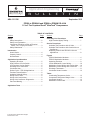
1
Application
Engineering
Application
Engineering
B
U
B
L
U
L
L
E
L
T
I
E
N
T
AE4-1311 R6
AE4-1311 R6
I
N
September 2011
ZPS20 to ZPS60K4 and ZPS20 to ZPS60K5 R-410A
1.5 to 5 Ton Copeland Scroll® UltraTech® Compressors
Section
TABLE OF CONTENTS
Page
Section
Safety
Safety Instructions............................................... 2
Safety Icon Explanation ...................................... 2
Instructions Pertaining to Risk of Electrical
Shock, Fire, or Injury to Persons ...................... 3
Safety Statements ............................................... 3
Assembly Line Procedures
High Potential (Hipot) Testing.............................. 7
Service Procedures
Unloader Test Procedure with 24 Volts ............... 7
Unloader Test Procedure with Comfort Alert or
CoreSense ........................................................ 7
Replacing ZPS*K4 with ZPS*K5 in Service
Applications ...................................................... 8
Introduction
How It Works ....................................................... 4
Capacity Control.................................................. 4
Nomenclature ...................................................... 4
Figures
ZPS*K4 Modulation Hardware ............................ 4
ZPS*K5 Modulation Hardware ............................ 4
Operating Envelope ............................................ 9
24 Volt Modulation Control Wiring ...................... 10
Modulation Control Wiring with Comfort Alert .... 10
Modulation Control Wiring with CoreSense ...... 11
Discharge Thermostat ........................................ 11
Crankcase Heater Location................................ 12
Application Considerations
Operating Envelope ............................................ 5
High Pressure Cut-Out Switch ............................ 5
Low Pressure Cut-Out Switch ............................. 5
Discharge Line Thermostat ................................. 5
Crankcase Heat .................................................. 5
Defrost Cycle – ZPS*K4 Applications.................. 5
Transient Sound Solution .................................... 6
Unloader Solenoid Wiring ................................... 6
Wiring with 24 Volts ............................................. 6
Wiring with Comfort Alert® ................................... 6
Wiring with CoreSense™ Diagnostics .................. 6
Part-Load Starting ............................................... 6
Tables
Condensing Temperature Limits ........................ 13
Compressor Refrigerant Charge Limits.............. 13
Crankcase Heaters ............................................ 13
Modulation Control Data .................................... 14
Application Tests .................................................... 7
© 2011 Emerson Climate Technologies
Printed in the U.S.A.
Page
1
Application Engineering
B
U
L
L
E
T
I
N
AE4-1311 R6
Safety Instructions
Copeland Scroll® compressors are manufactured according to the latest U.S. and European Safety
Standards. Particular emphasis has been placed on the user's safety. Safey icons are explained below
and safety instructions applicable to the products in this bulletin are grouped on Page 3. These
instructions should be retained throughout the lifetime of the compessor. You are strongly advised
to follow these safety instructions.
Safety Icon Explanation
DANGER
DANGER indicates a hazardous situation which, if not avoided, will result
in death or serious injury.
WARNING
WARNING indicates a hazardous situation which, if not avoided, could
result in death or serious injury.
CAUTION
CAUTION, used with the safety alert symbol, indicates a hazardous
situation which, if not avoided, could result in minor or moderate injury.
NOTICE
CAUTION
© 2011 Emerson Climate Technologies
Printed in the U.S.A.
NOTICE is used to address practices not related to personal injury.
CAUTION, without the safety alert symbol, is used to address practices
not related to personal injury.
2
Application Engineering
B
U
L
L
E
T
I
N
AE4-1311 R6
Instructions Pertaining to Risk of Electrical Shock, Fire, or Injury to Persons
WARNING
WARNING
WARNING
CAUTION
ELECTRICAL SHOCK HAZARD
• Disconnect and lock out power before servicing.
• Discharge all capacitors before servicing.
• Use compressor with grounded system only.
• Molded electrical plug must be used in all ZPS*K5 applications.
• Refer to original equipment wiring diagrams.
•
• Failure to follow these warnings could result in serious personal injury.
PRESSURIZED SYSTEM HAZARD
• System contains refrigerant and oil under pressure.
• Remove refrigerant from both the high and low compressor side before
removing compressor.
•
• Never install a system and leave it unattended when it has no charge,
a holding charge, or with the service valves closed without electrically
locking out the system.
• Use only approved refrigerants and refrigeration oils.
• Personal safety equipment must be used.
• Failure to follow these warnings could result in serious personal injury.
BURN HAZARD
• Do not touch the compressor until it has cooled down.
• Ensure that materials and wiring do not touch high temperature areas of
the compressor.
• Use caution when brazing system commponents.
• Personal safety equipment must be used.
• Failure to follow these warnings could result in serious personal injury or
property damage.
COMPRESSOR HANDLING
• Use the appropriate lifting devices to move compressors.
• Personal safety equipment must be used.
• Failure to follow these warnings could result in personal injury or
property damage.
Safety Statements
• Refrigerant compressors must be employed only for their intended use.
•
install, commission and maintain this equipment.
•
• All valid standards and codes for installing, servicing, and maintaining electrical and
refrigeration equipment must be observed.
© 2011 Emerson Climate Technologies
Printed in the U.S.A.
3
Application Engineering
B
U
L
L
E
Introduction
T
I
N
AE4-1311 R6
the compression process, there are several pockets
within the scroll that are compressing gas. Modulation
is achieved by venting a portion of the gas in the first
suction pocket back to the low side of the compressor
thereby reducing the effective displacement of the
compressor. Full capacity is achieved by blocking
these ports, thus increasing the displacement to 100%.
When the solenoid is energized the compressor is in
full-load or 100% of its capacity. When the solenoid
is de-energized the compressor is in part-load or
approximately 67% of its full load capacity. The loading
and unloading of the two step scroll is done “on the
fly” without shutting off the motor between steps. The
unloaded mode default was chosen for two reasons:
The ZPS*K4 and ZPS*K5 two step modulated Copeland
Scroll® compressors are ideally suited for residential
and light commercial applications where a capacity
step reduction and part load efficiency are important.
The ZPS*K4 is based upon the very successful
ZP*K3 fixed capacity scrolls. The ZPS*K5 compressor
family is the second generation of Copeland Scroll
UltraTech.® The ZPS*K5 is based on the field proven,
fixed capacity ZP*K5 product family and has improved
part load and full load performance versus the first
generation of Copeland Scroll UltraTech, ZPS*K4.
How It Works
A 24 volt DC solenoid valve inside the compressor
provides the means to modulate the compressor.
When the solenoid valve is energized the compressor
is in full-load and when de-energized the compressor
is in part-load. When the solenoid is energized in the
ZPS*K4 compressor, a modulation ring moves and
closes the modulation ports on the fixed scroll. When
the ZPS*K5 solenoid is energized a 3-way solenoid
valve provides pressure to a lift ring assembly that is
used to open and close the scroll modulation ports.
1. It is expected that the majority of run hours will be
in the low capacity, unloaded mode.
2. It allows a simple two-stage thermostat to control
capacity through the second stage in both cooling
and heating.
Nomenclature
The model numbers of the Copeland Scroll UltraTech
compressors include the approximate nominal 60
Hz capacity at AHRI operating conditions of 45°F
(7.2°C) evaporating temperature and 130°F (54.4°C)
condensing temperature. An example would be the
ZPS49K5E-PFV which has 49,100 Btu/hr (14.4 kW)
at the above mentioned full load condition. Both
full and part load performance data are published
throughout the entire operating envelope and can be
found in the Online Product Information (OPI) at www.
EmersonClimate.com.
A single-speed motor continues to run while the scroll
modulates between the two capacity steps. Please see
Figures 1 and 2, which show ZPS*K4 and ZPS*K5
hardware differences respectively.
Capacity Control
The compression process of a scroll compressor
is described in AE4-1331, Figure 9. At any point in
Snap Ring
Modulation Ring
Manifold, Filters
And Gasket
Modulation Ring
Modulation Seal
Lift Ring
Three Way Valve
Solenoid
Assembly
Figure 1 – ZPS*K4
© 2011 Emerson Climate Technologies
Printed in the U.S.A.
Figure 2 – ZPS*K5
4
Application Engineering
B
U
L
L
E
APPLICATION CONSIDERATIONS
T
I
N
AE4-1311 R6
temperatures do not come into contact with these
potentially hot areas.
In most respects the two step modulated scroll will
operate like a standard scroll in both the high and
low capacity mode. The basic application guidelines
in AE4-1331 should be adhered to for ZPS*K5
compressors, and bulletins AE4-1331 and AE4-1365
for ZPS*K4 compressors.
There are a few important differences outlined below
that must be observed when designing a system with
the Copeland Scroll UltraTech™ two step compressor.
A discharge line thermostat is recommended for
all air-source heat pump ZPS*K4 applications
because those compressors do not have internal
discharge temperature protection. The maximum
allowable discharge temperature is 275°F (135°C).
Mount the discharge thermostat as close as possible to
the compressor discharge fitting and insulate well. See
Figure 7 for recommended Emerson part numbers.
Operating Envelope
Crankcase Heat
The maximum operating condensing pressure varies
for the ZPS*K4 compressors. Please see Figure 3 and
Table 1 for condensing pressure limits. The maximum
condensing limit is the point where the compressor
can still run with a low supply voltage of 197 for the
-PFV (208-230 volt) and -10% for all other motors. The
ZPS compressors can operate at both full and partload capacity throughout the entire specified operating
envelope shown in Figure 3. The envelope represents
safe operating conditions with 20F° (11K) superheat in
the return gas.
A crankcase heater is recommended on single-phase
compressors when the system charge is over the
charge limit shown in Table 2. A crankcase heater is
required for systems containing more than 120% of the
compressor refrigerant charge limit listed in Table 2.
This includes long line length systems where the extra
charge will increase the standard factory charge above
the 120% limit.
A crankcase heater is required for three-phase
compressors when the system charge exceeds the
compressor charge limit listed in Table 2. Available
crankcase heaters are listed in Table 3. Refer to Figure
8 for proper installation of the crankcase heater.
High Pressure Control
A high-pressure cut-out is not required for UltraTech™
applications, but recommended for the highest level of
system reliability.
WARNING! Crankcase heaters must be properly
grounded.
If a high-pressure cut-out control is used the maximum
setting should not exceed 650 psig (45 bar). The
high pressure cut-out control should have a manual
reset for the highest level of system protection. It is
not recommended to use the compressor to test
the high pressure switch function during the unit
assembly line run test.
Defrost Cycle – ZPS*K4 Applications
During a defrost cycle, when the reversing valve abruptly
changes the refrigerant flow direction the suction and
discharge pressures will go outside of the normal
operating envelope. During this transition the scrolls will
be unloaded as the system transitions from heating to
cooling and then from cooling back to heating. The sound
that the compressor makes during this transition period is
normal and the duration of the sound will depend on the
coil volume, outdoor ambient temperature, and system
charge. The preferred method of mitigating defrost sound
is to shut down the compressor for 20 to 30 seconds
when the reversing valve changes position going into and
coming out of the defrost cycle. This technique allows
the system pressures to reach equilibrium without the
compressor running.
Low Pressure Control
NOTICE
A low pressure cut-out control is required on all
ZPS*K4 applications. A low pressure cut-out is
recommended on all ZPS*K5 applications for the
highest level of system reliability. The low pressure cutout should be set no lower than 20 psig (1.4 bar) for
heat pumps and 55 psig (3.8 bar) for air-conditioning
units.
CAUTION Reversing valve sizing must be within
the guidelines of the valve manufacturer. Required
pressure drop to ensure valve shifting must be
measured throughout the operating range of the
unit and compared to the valve manufacturer’s
data. Low ambient heating conditions with low flow
rates and low pressure drop across the valve can
Discharge Line Thermostat
CAUTION
Compressor top cap temperatures can be very
hot. Care must be taken to ensure that wiring or
other materials which could be damaged by these
© 2011 Emerson Climate Technologies
Printed in the U.S.A.
5
Application Engineering
B
U
L
L
E
result in a valve not shifting. This can result in a
condition where the compressor appears to be not
pumping (i.e. balanced pressures). It can also result
in elevated compressor sound levels.
T
I
N
AE4-1311 R6
Wired with Comfort Alert®
Please read Forms No. 2006ECT-54 and 2005ECT191 to understand the functioning of this module.
Comfort Alert is a diagnostic tool that is installed
separately in the electrical box of the unit. It monitors
and analyzes the status of the scroll compressor and
detects and communicates any system or compressor
problems without using external sensors that would
have to be installed into the system. Any faults are
translated through a blinking LED that can guide the
technician quickly and accurately to the root cause of
a problem. A simple wiring diagram with Comfort Alert
is shown in Figure 5.
Defrosting with the compressor in full load, versus
part load, will help defrost the outdoor coil in a shorter
period of time and will also help the reversing valve
shift positions during low outdoor ambient temperatures
when flow conditions can be low.
Transient Sound Solution
The transient sound solution will be implemented in the
UltraTech® ZPS*K5 family beginning in January, 2012
(serial number 12A). The transient sound solution is a
design improvement that provides improved compressor
sound quality during defrost and other transient
conditions. The transient sound solution consists of
several patented features that provide stability to the
scrolls when axial loading is low and intermediate cavity
pressure relief during an extreme flooded start condition.
De-energizing the compressor at the beginning and end
of the defrost cycle is no longer necessary to mitigate
compressor sound during defrost transition for ZPS*K5.
Transient sound solution enables full load starting and
eliminates the compressor requirement for a highpressure cut-out control.
In addition to diagnostics, Comfort Alert provides
application benefits when used with Copeland Scroll
UltraTech™. A few of those benefits that are related to
the modulation aspect of UltraTech include:
1. A solenoid power saving feature for ZPS*K4
compressors where the solenoid VA load is
reduced from 20 to 6VA.
2. Comfort Alert ensures part-load starting by
delaying the Y2 signal to the solenoid for 5 seconds
after start-up. This is a definite starting advantage
under low voltage conditions.
3. If the internal overload trips in the compressor
the Comfort Alert will de-energize the solenoid,
preventing an overheat condition of the solenoid
coil.
Unloader Solenoid Wiring
Standard Wiring with 24 Volts
A nominal 24-volt direct current coil activates the
internal unloader solenoid in the ZPS*K4 and ZPS*K5
compressors. The input control circuit voltage must
be 18 to 28 volt AC or DC. The maximum solenoid VA
is 20 and 5 for the ZPS*K4 and ZPS*K5 respectively.
The external solenoid electrical connection is made
with a molded plug assembly, Emerson part number
529-0061-00. This plug contains a full wave rectifier to
supply direct current to the unloader coil if the control
circuit is AC. If the control circuit is DC, the same plug
with the full wave rectifier can be used as the full wave
rectifier will have no effect on the DC voltage input. The
rectified molded plug can be sourced from some of the
same suppliers of the molded electrical plug used to
power the compressor motor. A simple wiring diagram
is show in Figure 4.
4. The full wave rectifier circuit is incorporated into
Comfort Alert, allowing a lower cost molded plug
without the full wave rectifier.
Wired with CoreSense™ Diagnostics
CoreSense for UltraTech provides both diagnostics
and active protection, in addition to the modulation
features offered by Comfort Alert. Please read AE81379 for more information on CoreSense Diagnostics
for UltraTech. A simple wiring diagram for CoreSense
is shown in Figure 6.
Table 4 lists Comfort Alert, CoreSense and molded
plug part numbers for various types of applications.
Part-Load Starting
NOTICE
There are a number of benefits associated with starting
the UltraTech compressors in part-load. Improved
starting is realized during a low voltage and/or flooded
start condition whereby stress on the motor, scrolls,
and 3-way modulation valve is significantly reduced.
Starting in part-load can result in the compressor
starting and accelerating to full speed faster, thereby
The current in the ZPS*K5 solenoid modulation
circuit must be less than 0.9 mA during part-load
for the solenoid valve to change positions. A time
delay relay or another current consuming load inseries with the modulation solenoid could result in
current greater than 0.9 mA.
© 2011 Emerson Climate Technologies
Printed in the U.S.A.
6
Application Engineering
B
U
L
L
E
reducing the perception of light dimming. Part-load
starting also reduces the inrush current on the 24 volt
transformer.
I
N
off. Apply 18 to 28 volt AC to the unloader molded
plug leads and listen for a click as the solenoid
pulls in. Remove power and listen for another click
as the unloader returns to its original position. If
clicks can’t be heard, proceed to Step 3.
For the highest level of system reliability, part-load
starting is recommended for for all ZPS*K4 & ZPS*K5
UltraTech® compressors.
3. Shut off power and remove the control circuit
molded plug from the compressor and measure
the unloader solenoid coil resistance. The
solenoid coil should have continuity and not be
grounded or have infinite resistance. If the coil
resistance is infinite, zero, or grounded, the
compressor must be replaced.
APPLICATION TESTS
Refer to the Application Tests section of AE4-1331
for the application tests to run to help ensure a reliable
application. Consult with your Emerson Climate
Technologies Application Engineer if interpretation of
application test results is required.
4. Check the molded plug.
ASSEMBLY LINE PROCEDURES
Voltage check: Apply control voltage to the
plug wires (18 to 28 volt ac). The measured DC
voltage at the connectors in the plug should be
around 15 to 27 VDC.
“Hipot” (AC High Potential) Testing
CAUTION
Resistance check: Measure the resistance from
the end of one molded plug lead to either of the
two female connectors in the plug. One of the
connectors should read close to zero ohms while
the other should read infinity. Repeat with other
wire. The same female connector as before should
read zero while the other connector again reads
infinity. Reverse polarity on the ohmmeter leads
and repeat. The female connector that read infinity
previously should now read close to zero ohms.
Use caution with high voltage and never hipot
when compressor is in a vacuum.
If the 24 volt modulation solenoid circuit is dielectric
(hipot) strength tested, the maximum applied voltage
should not exceed 1,000 volts RMS for 1 second at
2.0mA maximum leakage current.
Refer to the Assembly Line Procedures section of
AE4-1331 for additional guidelines to follow for OEM
assembly line processes.
Replace plug if either of these test methods
doesn’t show the desired results.
SERVICE PROCEDURES
Unloader Test Procedure with Comfort Alert ® or
CoreSense™
CAUTION
Use caution when troubleshooting energized
circuits.
If it is suspected that the unloader is not working, the
following methods may be used to verify operation.
Unloader Test Procedure with Standard 24 Volt
Wiring
1. Operate the system and measure compressor
amperage. Cycle the unloader on and off at ten
second intervals by applying and removing Y2
voltage to the module. Wait five seconds after
power is applied to Y2 before taking a reading.
An increase in compressor amperage should be
observed when switching from part-load to full-load
and a reduction in compressor amperage should
be observed when changing from full-load to part
load. The percent change in current depends on
the operating conditions and voltage.
If it is suspected that the unloader is not working, the
following methods may be used to verify operation.
1. Operate the system and measure compressor
amperage. Cycle the unloader on and off at ten
second intervals. An increase in compressor
amperage should be observed when switching
from part-load to full-load and a reduction in
compressor amperage should be observed when
changing from full-load to part load. The percent
change in current depends on the operating
conditions and voltage.
2. If Step 1 does not give the expected results remove
the solenoid plug from the compressor and with
the unit running and the thermostat calling for Y2
to be energized test the voltage output at the plug
2. Step 2 applies to ZPS*K4 compressors only.
For ZPS*K5 compressors proceed to Step 3. If
Step 1 does not give the expected results shut unit
© 2011 Emerson Climate Technologies
Printed in the U.S.A.
T
AE4-1311 R6
7
Application Engineering
B
U
L
L
E
with a dc voltmeter. The reading should be 4 to
18 volts when Comfort Alert® is used with ZPS*K4
compressors and 18 to 28 volts when Comfort Alert
or CoreSense™ is used with ZPS*K5 compressors
(see Table 4 for Comfort Alert and CoreSense
part numbers). If not, unplug the harness from
the module and check voltage at the “DC Sol”
pins of the module. The module will not power
the unloader solenoid if the compressor is not
running or Fault Code 1 or 9 is active.
I
N
Special consideration needs to be given to the
compressor contactor since some ZPS*K5 compressors
have higher RLA and LRA values than the ZPS*K4
compressor that is being replaced. In some cases
the system contactor may need to be upsized. The
run capacitor may need to be changed to match the
specification called for by the new ZPS*K5 compressor.
The allowable tolerance on run capacitors is +5 to -0
microfarads. If the ZPS*K4 compressor being replaced
has a start capacitor and relay for light dimming,
the replacement compressor must have a new start
capacitor and relay of the correct ratings or no start kit
at all. For more information on compressor electrical
data please refer to the Online Product Information
at www.EmersonClimate.com.
3. If the correct DC voltage is at the control circuit
molded plug measure the unloader coil resistance.
The solenoid coil should have continuity and not
be grounded or have infinite resistance. If the
coil resistance is infinite, zero, or grounded, the
compressor must be replaced.
The ZPS*K5 modulation solenoid is not compatible
with the power saving feature in some Comfort Alert
modules. To work around this, a modulation adapter
plug containing a resistive-capacitive circuit will be
shipped with the service compressor. This plug must
be used with the replacement compressor if the
system employs Comfort Alert part numbers 5430033-00 or 543-0069-01.
Replacing ZPS*K4 with ZPS*K5 in Service
Applications
ZPS*K5 compressors will be used to replace ZPS*K4 in
service applications when the K4 compressor family is
phased out of production in 2013. K5 compressors have
the same mounting configuration and approximately the
same tube location as the K4 compressors. K5 service
compressors will be shipped with a molded electrical
plug since K5 compressors are configured only with
molded plug type electrical connections.
© 2011 Emerson Climate Technologies
Printed in the U.S.A.
T
AE4-1311 R6
For more information on service practices refer to
Service Procedures in AE4-1331.
8
Application Engineering
B
U
L
L
E
T
I
AE4-1311 R6
N
150
*See Table 1
Condensing Temperature (°F)
140
130
120
110
100
90
80
70
-20
-10
0
10
20
30
40
50
60
Evaporating Temperature (°F)
65
*See Table 1
60
Condensing Temperature (°C)
55
50
45
40
35
30
25
-25
-20
-15
-10
-5
0
Evaporating Temperature (°C)
Figure 3
Operating Envelope
© 2011 Emerson Climate Technologies
Printed in the U.S.A.
9
5
10
15
Application Engineering
B
U
L
L
E
T
2 - Stage
Thermostat
Indoor
Unit
Outdoor
Unit
C
C
C
I
CC
R
R
R
Y1
Y1
Y1
Y2
Y2
Y2
N
AE4-1311 R6
Compressor
Contactor
Rectified
Molded Plug
Figure 4
Example of 24 Volt Modulation Control Wiring
Comfort
Alert
2 - Stage
Thermostat
Indoor
Unit
Outdoor
Unit
Y2
Y2
Y2
Y2
Y1
Y1
Y1
Y
High/Low
Pressure Switch
L
L
L
R
R
R
L
R
Compressor CC
Contactor
C
C
C
C
DC
Solenoid
Figure 5
Example of Modulation Control Wiring With Comfort Alert
© 2011 Emerson Climate Technologies
Printed in the U.S.A.
10
UltraTech
Solenoid
Application Engineering
B
U
L
L
E
2 - Stage
Thermostat
Indoor
Unit
Outdoor
Unit
Y2
Y2
Y2
Y1
Y1
Y1
T
I
N
AE4-1311 R6
CoreSense
Y2
Y
High/Low
Pressure Switch
L
L
L
R
R
R
L
R
Compressor CC
Contactor
C
C
C
C
Prot
DC
Solenoid
Figure 6
Example of Modulation Control Wiring With CoreSense
Kit Part No.
Max.
Voltage
Max. Contact
Rating
998-0540-02
240
5A @ 240V
998-7022-02*
240
5A @ 240V
*For conduit use.
Figure 7
Discharge Thermostat
© 2011 Emerson Climate Technologies
Printed in the U.S.A.
11
UltraTech
Solenoid
Application Engineering
B
U
L
L
E
T
I
N
AE4-1311 R6
Seam Weld
ZPS20-40K4 & ZPS35 -60K5 1
ZPS49-60K4 2
ZPS20-30K5
WARNING
Verify the correct crankcase heater
voltage for the application and ensure
heater is properly grounded.
Figure 8
Crankcase Heater Location
© 2011 Emerson Climate Technologies
Printed in the U.S.A.
12
0.20-0.47” (5.0 -12.0 mm) 1
0.37-1.61” (9.5 -41.0 mm) 2
Seam Weld
0.20-1.22” (5.0 -31.0 mm)
Connect the heater so that the connection point straddles the compressor seam weld
Application Engineering
B
U
L
L
E
T
I
AE4-1311 R6
N
Table 1
Model
Max Condensing Temp
ZPS20,30,40,49,51K4
140°F/60°C
ZPS26,35,60K4
145°F/63°C
All ZPS*K5
145°F/63°C
Table 2 - Compressor Refrigerant Charge Limits
Charge Limit
120% x Limit**
Model
Frame
Size*
Pounds
kg
Pounds
kg
ZPS20 - 30K5
53
8
3.6
9.6
4.3
ZPS35 - 60K5
63
10
4.5
12.0
5.4
ZPS20 - 40K4
63
10
4.5
12.0
5.4
ZPS49 - 60K4
70
10
4.5
12.0
5.4
*Approximate Shell Diameter (e.g. 63 = 6.5 Inches)
**Charge Allowance For System
Table 3 – Crankcase Heaters
Model
Frame Size
ZPS20-30K5
53
ZPS20 - 40K4
ZPS35 - 60K5
ZPS49 - 60K4
© 2011 Emerson Climate Technologies
Printed in the U.S.A.
63
70
Volts
Watts
Leads
Emerson Part No.
240
40
21”
018-0094-00
120
40
21”
018-0094-01
240
40
21”
018-0096-00
120
40
21”
018-0096-01
480
40
21”
018-0096-02
575
40
21”
018-0096-03
240
40
48”
018-0096-04
480
40
48”
018-0096-05
240
70
21”
018-0095-00
480
70
21”
018-0095-01
575
70
21”
018-0095-02
120
70
48”
018-0095-07
400
70
48”
018-0095-08
277
70
21”
018-0095-09
13
Application Engineering
571-0072-00
Rectified Molded Plug
Non Rectified Molded Plug
1
2
529-0062-00
N/A
543-0038-01
543-0122-00
543-0122-00
543-0038-01
543-0069-01
543-0124-00
543-0033-01
543-0033-00
N
529-0061-00
529-0061-00
18-28
5
ZPS*K5
not applicable
20
ZPS*K4
Model
I
18-28
CoreSense
3-Phase
WSHP
3-Phase
AC&HP
1-Phase
WSHP
1-Phase
AC&HP
Molded
Plug1
Voltage
Range
24 Volts AC/DC
Control
Maximum
Allowable
De-Energized
Current
Maximum
Solenoid
VA
T
529-0062-00
E
0.9 mA
L
Molded Plug2
L
Comfort Alert/CoreSense Control, Module & Plug Part Numbers
U
Table 4
B
AE4-1311 R6
The contents of this publication are presented for informational purposes only and they are not to be construed as warranties or guarantees, express or implied, regarding the products or
services described herein or their use or applicability. Emerson Climate Technologies, Inc. reserves the right to modify the designs or specifications of such products at any time without
notice. Emerson Climate Technologies, Inc. does not assume responsibility for the selection, use or maintenance of any product. Responsibility for proper selection, use and maintenance of
any Emerson Climate Technologies, Inc. product remains solely with the purchaser and end-user.
© 2011 Emerson Climate Technologies
Printed in the U.S.A.
14