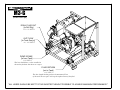
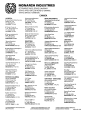
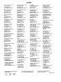
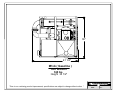
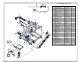
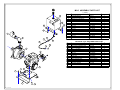
1
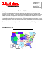
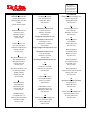
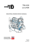
Surface to Surface
Operators Manual
** M-3G **
Unit Serial No. _______________
Robin Engine
EH30 – Serial No. ______________
EH34 – Serial No. ______________
Monarch Pump
TSP-3 – Serial No. ________________
Filter Part Numbers
Robin Air Filter No. 234-32604-07
Gasoline Filter No. CQ 86001
STS-009 Rev. 01/05
Surface to Surface
M3-G
CAUTIONS
The following caution statements have been drawn from the instructions in this manual. They
have been assembled here for ready reference.
Operating
BEFORE starting or restarting the engine and centrifugal pump, make sure any valves installed on
the pump intake line are open.
BEFORE STARTING OR RUNNING THE ENGINE BE SURE THE PUMP IS PRIMED! This is
checked by slowly unscrewing the plug on the top of the centrifugal pump. Water will leak out as the
plug is loosened or a visual inspection can be made if the plug is removed. The centrifugal pump
WILL be damaged if allowed to cavitate or run dry.
WHEN transferring, the flow to the drill rig may reach up to 35 p.s.i. Check the drill rig
manufacturers specifications regarding maximum inlet pressures allowed for their pump.
REMEMBER that the system is pumping fluid under pressure, even when the engine is idling.
THE stone trap (volute) of the centrifugal pump should be cleaned at least weekly and any trash
removed.
AVOID allowing foreign material into the Venturi Mixing Tee thru the hopper (i.e.: bag parts, stones,
leaves etc) by keeping the valve closed at all times.
NEVER allow fingers or objects such as sticks, screwdrivers, metal bars etc. to enter the tee in an
attempt to clear it. Serious personal injury or damage to the butterfly valve will result.
NEVER attempt repairs or disassembly without shutting off the unit. Serious personal injury will
result.
TRAPPED fluid may be present and will spill out when piping, hoses, pump front cover or
filter/shear are removed.
IMPROPER installation of the mechanical seal will result in leakage and possible damage to the seal.
All maintenance, operating and repair of this unit, must be done per the instructions in the operators
manual for safety and reliability.
DO NOT position any part of your body over the hopper when cleaning with the wash wand.
Surface to Surface
M3-G
CAUTIONS continued
CARE must be taken that the coupler gaskets are properly installed or a leak may develop.
IT is imperative that all suction line connections do not leak. The M3-G uses the vacuum created by
the venturi jetting to draw fresh water into the reservoir tank.
NEVER leave liquid in the pump casing in freezing weather conditions, damage will result. Follow
instruction in this operator manual for winterizing.
IF the intent is to take water from a ditch or pond, it is recommended that a very fine screen be
placed over the inlet of the hose, to stop the introduction of foreign material into the M3-G system.
Alternative Uses & Moving
CAUTION should be used when considering alternative uses for this equipment. This unit was
designed for mixing & blending of bentonite and drilling additives. The manufacturer should be
consulted.
WHEN lifting this unit, the polyethylene tank must be empty of fluid or damage may result.
LIFTING lugs or the lift points identified in the skid structure must be used in order to safely lift the
unit.
Safety Markings
Hazard and warning markings have been placed at appropriate points on the unit. International symbols
have been used, in order to ensure universal understanding of the nature of the hazard. Please comply
with all warnings and markings to ensure safe use of the equipment. These include but are not limited to:
a)
Lifting points
b)
Flammable liquids
c)
High temperature areas
d)
Eye protection recommendations
e)
Ear protection recommendations
f)
Dust mask recommendations
g)
Manual requirements
h)
Accessibility restrictions.
Surface to Surface Inc.
M3-G
(Hose Hook-ups)
DRILL FLUID OUT
[to Drill Rig]
** 1 1/2" NPT **
OUT FLOW
[to Tank Gun(s)]
** 1 1/2" NPT **
PUMP INTAKE
[in from Tank]
** 3" NPT **
This line should have a valve installed at
the tank to facilitate shut down or reapirs.
FLUID RETURN
[out to Tank]
** 3" NPT **
This line should discharge above the maximun fill line
of the tank. The air space will stop the siphon action of the fluid.
"ALL HOSES SHOULD BE KEPT TO THE SHORTEST LENGHT POSSIBLE TO ACHIEVE MAXIMUN PREFORMANCE."
Surface to Surface
M3-G
Operators Manual
Congratulations on your acquisition of the patented (U.S. 5,779,355) M3-G Mixing System. You have
acquired the fastest and most efficient mixing system manufactured for mixing Bentonite drilling slurry
(mud). As a manufacturer of HDD support equipment, we are well aware of the extreme conditions that
HDD equipment is exposed to on a daily basis. Surface To Surface strives to overcome these
conditions, with better design and manufacturing practices. Please feel free to call our toll free number
(1-800-567-0978) if you have any questions or concerns about your M3-G.
Thank you, for choosing the M3-G
The M3-G mixing unit was designed to mix dry or liquid drilling products with clean water, into a slurry.
The slurry is continually circulated through the mixing cycle until it reaches the desired consistency. The
operator can then transfer the final product to a holding reservoir or directly to the drilling equipment.
WHEN transferring, the flow to the drill rig may reach up to 35 p.s.i. Check the drill rig
manufacturers specifications regarding maximum inlet pressures allowed for their pump.
The M3-G mixing unit consists of a gasoline powered centrifugal pump, filter/shear unit, venturi mixing tee
assembly, dry hopper and table, pressure wash wand and a set of tank internal jet guns. These components
are all mounted on a frame type skid, built for lifting or solid mounting. For ease of interpretation, looking at
the mixing unit hopper straight on will be considered looking at the front of the unit. Hence the other side,
will be the rear and the ends will be right or left end.
LIFTING lugs or the lift points identified in the skid structure must be used in order to safely lift the
unit.
Care and Maintenance
Gasoline Powered Centrifugal Pump
Care and maintenance of the engine and pump are covered in the manufacturer operators manuals supplied.
However, we suggest the following daily checks be carried out prior to using the system. Check the gasoline
fuel tank is full. Check oil level by removing the oil plug / dip stick, and viewing the level. Check the engine
air filter (due to environmental conditions). Check that the water suction tee valve is open and the reservoir
tank has sufficient liquid to supply the centrifugal pump.
B BEFORE starting or restarting the engine and centrifugal pump, make sure any valves installed on
the pump intake line are open.
BEFORE STARTING OR RUNNING THE ENGINE BE SURE THE PUMP IS PRIMED! This is
checked by slowly unscrewing the plug on the top of the centrifugal pump. Water will leak out as the
plug is loosened or a visual inspection can be made if the plug is removed. The centrifugal pump
WILL be damaged if allowed to cavitate or run dry.
IMPROPER installation of the mechanical seal will result in leakage and possible damage to the seal.
All maintenance, operating and repair of this unit, must be done per the instructions in the operators
manual for safety and reliability.
NEVER leave liquid in the pump casing in freezing weather conditions, damage will result.
Surface to Surface
M3-G
Filter / Shear System
The filter / shear system on the M3-G is an integral part of the mixing system and to operate efficiently
requires daily cleaning of the stainless steel internal filter /shear. The filter / shear system is a two-piece unit
consisting of an outside housing and an internal filter / shear. The filter / shear will trap any debris, such as
parts of bags, stones, leaves grass etc. The proper procedure for cleaning the filter shear is to close any
valve(s) in the suction line, from the reservoir tank to the pump, remove the 5 inch Snap Lock coupler at the
left end of the filter housing, remove the 3 inch Snap Lock coupler at the discharge port of the centrifugal
pump. You will now be able to remove the internal filter / shear from the housing, after the internal filter /
shear has been removed, you will see on the end of the filter / shear a cover plate. Remove the cover plate and
wash out the filter / shear with clear water. Reinstall the cover plate on the filter, reinstall the filter in the
housing (Note the small block on the bottom of the screen, this is placed on the bottom of the filter housing to
line up the 5 inch Snap Lock coupler and gasket) do-not clamp the 5 inch coupler until the 3 inch coupler and
gasket are properly lined up. After all pieces are correctly lined up, clamp the 5 inch coupler 1st and 3 inch
coupler 2nd and reinstall the safety pins.
NEVER attempt repairs or disassembly without shutting off the unit. Serious personal injury will
result.
TRAPPED fluid may be present and will spill out when piping, pump front cover or filter/shear is
removed.
BEFORE STARTING OR RUNNING THE ENGINE BE SURE THE PUMP IS PRIMED! This is
checked by slowly unscrewing the plug on the top of the centrifugal pump. Water will leak out as the
plug is loosened or a visual inspection can be made if the plug is removed. The centrifugal pump
WILL be damaged if allowed to cavitate or run dry.
BEFORE starting or restarting the engine and centrifugal pump, make sure the butterfly valve on the
pump intake line is open.
CARE must be taken that the coupler gaskets are properly installed or a leak may develop.
Pressurized Wash Wand
The wash wand is a maintenance tool used to clear obstruction and build-up in the jetting TEE under the
hopper. The wand uses the fluid circulating thru the system and the pressure of the pump to produce a
concentrated stream of fluid to aid in dislodging build-up around the jetting nozzle and hopper valve. DO
NOT use the wash wand as a pry bar or scraper as damage may occur. Let the force of the fluid stream do
the work. To use the wash wand properly, first place the wand inside of the hopper, slowly open the valve
and direct the fluid stream down into the throat of the hopper. Caution should be taken to keep the wand out
of the stream exiting the jetting nozzle, as splash back will occur. After using the wash wand, it should be
stored back into its holder.
The wash wand may also be used to obtain a fluid sample for testing purposes. This will give the same
sample as the “Drill Fluid Out”. Caution should be taken, as the flow will have to be reduced. To get a good
sample, place the wand inside the hopper and open the valve slowly. Let fluid flow out of the wash wand to
remove all other fluid in the hose (approx. 20 sec.). Now take the sample, close the valve and return the wash
wand back to its holder.
DO NOT position any part of your body over the hopper when cleaning with the wash wand.
Surface to Surface
M3-G
Venturi Mixing Tee
The Venturi Mixing Tee is the very heart of this system and requires very little maintenance. However
M3-G parts may wear as a result of the application in time and require replacement. This wear will become
evident, when the operator notices a reduction in vacuum. The M3-G is also equipped with a pressure wand
for clearing obstructions and build-up in the jetting tee. It is recommended that the jetting tee be cleaned
with the wash wand after the introduction of material into the hopper.
AVOID allowing foreign material into the Venturi Mixing Tee thru the hopper i.e.: bag parts, stones,
leaves etc. by keeping the valve closed at all times.
NEVER allow fingers or objects such as sticks, screwdrivers, metal bars etc. to enter the tee in an
attempt to clear it. Serious personal injury or damage to the butterfly valve will result.
IT is imperative that the suction connections do not leak. The M3-G uses the vacuum created by the
venturi jetting to draw fresh water into the reservoir tank.
IF the intent is to take water from a ditch or pond, it is recommended that a very fine screen be
placed over the inlet of the hose, to stop the introduction of foreign material into the M3-G system.
Dry Hopper and Table
The Dry Hopper and Table are used during the initial mixing of the dry material and water. The hopper and
table require very little daily maintenance, however care should be used that this unit does not become
overloaded. There should never be more than 100 lb. in or on the hopper and table at any time. The hopper
and table are not a ladder, and should not be climbed on or sat on, damage can result. The wash wand may
be used to clean inside the hopper.
The 3 inch butterfly valve must be kept free of dried Bentonite, ice or other buildups to reduce the chance of
damage during opening and closing. The valve operates more smoothly if the surfaces are kept damp or wet.
All valves are to be opened and closed by hand. DO NOT FORCE ANY VALVE OPEN OR CLOSED,
visually check the valve if a problem occurs!
AVOID allowing foreign material into the Venturi Mixing Tee thru the hopper i.e.: bag parts, stones,
leaves etc. by keeping the valve closed at all times.
Tank Internal Jet Gun(s) (customer installed)
The Tank Internal Jet Gun(s) are to be located inside of a reservoir tank, Their function is to keep the slurry
product in the tank moving. This function assures the elimination of dead spots in the tank. The “Tank Gun”
valve should always be in the open position. The jet gun(s) requires little or no maintenance and will only
require attention if the jets become clogged. Flushing the entire system weekly with clear water should
eliminate any problems with this piece of the system.
The tank jet gun(s) also acts as a relief valve to the system and relieves the pressure spikes caused when the
flow to the drill rig or another reservoir tank, is interrupted.
ENTERING a tank is not recommended. Serious injury could result.
Surface to Surface
M3-G
OPERATING THE M3-G
Before Starting
•
•
•
•
•
•
•
•
•
•
•
READ engine operators manual for proper starting and running procedures.
CHECK to assure the engine oil level is correct. Refer to the operator manual supplied by the engine
manufacturer.
CHECK to assure the air filter is clean (replace if necessary).
CHECK to assure the gasoline fuel tank is full and the shut off valve is open.
CHECK to assure any valves installed on the pump intake line are open.
CHECK to assure there is sufficient fluid in the reservoir tank, to not run the centrifugal pump dry.
REMOVE the priming plug, check and/or fill pump casing with water, replace and tighten plug.
CHECK to assure the ball valve connected to the filter housing marked “Drill Fluid” is closed.
CHECK to assure the ball valve connected to the filter housing marked “ Tank Gun” is open.
CHECK that hopper valve is closed
CHECK that the wash wand valve is closed
Starting Engine
•
•
•
•
•
•
•
•
Set the speed control lever 1/3 of the way towards the high-speed position.
If the engine is cold or the ambient temperature is low, close the choke fully.
If the engine is warm or the ambient temperature is high, close the choke lever half-way, or keep it fully
open.
Pull the starter recoil handle slowly until resistance is felt. This is the compression point. Return the
starter recoil handle to its original position and pull swiftly. Do not pull out the rope all the way. After
starting the engine, allow the starter recoil handle to return to its original position while still holding the
handle.
After starting the engine, gradually open the choke until fully open. Do not fully open the choke lever
immediately when the engine is cold or the ambient temperature is low, or the engine may stop.
After the engine starts, set the speed control lever at the low speed position and warm it up without load
for a few minutes.
Remember that the system is pumping fluid under pressure, even when the engine is idling.
Gradually move the speed control lever toward the high-speed position and set at the required speed.
Note: Whenever high-speed operation is not required, slow the engine to down by moving the speed control
lever to save fuel and extend engine life.
The Robin / Monarch pump used on this unit is self-priming. Priming is not required as long as the pump is
kept full of liquid.
BEFORE STARTING OR RUNNING THE ENGINE BE SURE THE PUMP IS PRIMED! This is
checked by slowly unscrewing the plug on the top of the centrifugal pump. Water will leak out as the
plug is loosened or a visual inspection can be made if the plug is removed. The centrifugal pump
WILL be damaged if allowed to cavitate or run dry.
READ CAUTIONS AT FRONT OF MANUAL REGUARDING THIS OPERATION!
Surface to Surface
M3-G
Mixing Operation
•
•
•
•
•
•
•
Operate engine at high speed.
Open butterfly valve at bottom of hopper where it joins the venturi mixing tee.
Introduce the dry or liquid raw material into the hopper.
Suction created by the venturi mixing tee will draw the raw material into the jet stream for initial mixing.
Flush jetting tee with wash wand.
Close the butterfly valve on the hopper to keep debris out of the system.
Allow the mixing system to circulate the product until the desired consistency is attained.
READ CAUTIONS AT FRONT OF MANUAL REGUARDING THIS OPERATION!
Transferring Operation (product outflow)
•
•
•
•
•
On the left end of the skid base, you will see a 1-1/2 in. ball valve (1-1/2”NPT.) connected to the filter /
shear housing of the M3-G marked “Drill Fluid”.
A transfer hose with a minimum size of 1-1/2 in. is to be attached to the ball valve to carry the finished
product to a holding tank or direct to the drill rig.
Make the necessary connections at the holding tank or drill rig.
Run the M3-G pump at favorable speed and open the ball valve to allow the flow to the holding tank or
drill rig.
The speed and pressure of the fluid outflow is determined by the engine speed and valve setting.
READ CAUTIONS AT FRONT OF MANUAL REGUARDING THIS OPERATION!
Daily Shut Down
•
•
•
•
•
•
•
Set the speed control lever at the low speed position and allow the engine to run at low speed for 2 or 3
minutes.
Rotate the stop button until the engine stops. Do not stop engine suddenly while running at high speed.
Close the fuel cock.
Pull the recoil starter handle slowly until resistance is felt and then return the handle to its original
position. Note - This operation is necessary to prevent outside moist air from intruding into the combustion
chamber.
Close any valve(s) installed on suction line between pump and tank.
Remove filter / shear as described in maintenance section.
Clean filter / shear as described in maintenance section.
READ CAUTIONS AT FRONT OF MANUAL REGUARDING THIS OPERATION!
Surface to Surface
M3-G
Week End Shut Down
•
•
•
•
•
•
•
•
•
Pump or drain remaining mixed slurry product out of your tank and dispose of it according to local
environmental approved practices.
Make sure “Tank Gun” valve is open.
Rinse tank with clear water and then pump through the system, removing as much of the slurry mix in
the system as possible. Open the valve on the wash wand to flush with fresh water, back into hopper.
Drain the remaining water out of your tank and dispose of it according to local environmental approved
practices.
Remove centrifugal pump front cover and clean. Replace cover carefully to avoid damage to the seals.
DO NOT over tighten Tee handle nuts.
Make sure “Tank Gun” and wash wand valves are open.
Remove filter / shear and clean as described in the maintenance section of this manual.
Prolonged periods of storage require extra care of the pump to protect from rusting. Take pump apart to
dry and spray with a protective oil film.
Prolonged periods of storage require engine preparation. See engine operators manual.
READ CAUTIONS AT FRONT OF MANUAL REGUARDING THIS OPERATION!
Winter and Freezing Weather Shut Down
•
•
•
•
•
•
•
•
•
Pump or drain remaining mixed slurry product out of your tank and dispose of it according to local
environmental approved practices.
Make sure “Tank Gun” valve is open.
Rinse tank with clear water and then pump through the system, removing as much of the slurry mix in
the system as possible. Open the valve on the wash wand to flush with fresh water, back into hopper.
Drain the remaining water out of the tank and dispose of it according to local environmental approved
practices.
Remove centrifugal pump front cover and clean inside. Leave cover off. This will let remaining moisture
to drain.
Make sure “Tank Gun” and wash wand valves are open.
Remove filter / shear and clean as described in the maintenance section of this manual. Leave filter /
shear out of housing as this will allow remaining moisture to drain.
Open the hopper valve and pour in a suitable environmentally friendly anti-freeze.
Shut the hopper valve and pour a suitable environmentally friendly anti-freeze into the hopper until
about 2” of fluid cover the valve. This will stop the valve from freezing around the edges.
READ CAUTIONS AT FRONT OF MANUAL REGUARDING THIS OPERATION!
Surface to Surface
M3-G
Self Loading
•
If the self-loading feature of The M3-G is required, you will find a 1-1/2 in. NPT port located on the
venturi-mixing tee below the hopper. Remove the plug and install a full flow ball valve and a type of
quick coupler capable of being capped when not in uses. A non-collapsing hose (hard hose) can then be
installed.
READ CAUTIONS AT FRONT OF MANUAL REGUARDING THIS OPERATION!
NOTES:
Robin America, Inc
940 Lively Blvd.
Wood Dale,IL. 6091
phone: 630-350-8200
fax: 630-350-8212
[email protected]
Distribution Method
Robin Engines are distributed through a two-step distribution method. Robin America has established a network of
independent wholesale distributors throughout North America. Each of these distributors has a large inventory of Robin
engines and parts in their warehouse. The distributors set up and supply engines and parts to the dealers along with support
materials and information. The distributors also market Robin engines to small and medium size OEM (original equipment
manufacturer) accounts. Larger OEM accounts are handled directly by Robin America.
The thousands of Robin engine dealers provide advice, service, and replacement engines to end user customers. There are
many different types of retail dealers. Some specialize in servicing lawn and garden equipment, small construction equipment,
pumps, etc.. To find a dealer to service your Robin engine, we recommend that you contact your nearest Robin Engine
Distributor for list of dealers suitable for your needs. Please use the map above to locate your Robin Engine Distributor.
DISTRIBUTOR LIST
Select your area to find your Robin Engine Distributor
Robin America, Inc
940 Lively Blvd.
Wood Dale,IL. 6091
phone: 630-350-8200
fax: 630-350-8212
[email protected]
1
GEECOE Services Inc.
190-2851 Simpson Rd.
Richmond, BC V6X 2R2
Canada
phone: 604-278-4488
2
Renown Industries Ltd.
5608-94 A Street
Edmonton, Alberta
Canada, T6E 3E4
780-435-3447
3
Lambert Electric Ltd.
814 47th Street East
Saskatoon Saskatchewan
Canada, S7K 0X4
306-242-0370
4
M-K Power Products Corp.
5641 McAdam Road
Mississauga Ontario
Canada, L4Z 1N9
905-890-5323
M-K Power Products Corp.
751 Grandview Blvd.
Sudbury Ontario
Canada, P3A 4Z8
705-524-2529
5
Marindustriel Enr.
8550, Delmeade
Montréal, Quebec
Canada, H4T 1L7
514-342-2748
Marindustrial Inc.
75 Urquhart Ave., #5
Moncton, New Brunswick
Canada, E1H 2R4
506-852-3332
6
The Bentley Company
4109 Airport Way So.
Seattle WA 98108
800-628-5827
10 continued
Northern Engine and Supply, Inc.
2929 W. Superior St.
Duluth, MN 55806
218-628-2836
7
Southwest Products Corp.
5143 W. Roosevelt
Phoenix, AZ 85043
602-269-3581
[email protected]
11
Tri State Engine Service
6125 Valley Dr.
Bettendorf, IA 52722
800-289-8676
Southwest Products Corp.
2760 Junipero Ave.
Long Beach, CA90806
562-424-0913
[email protected]
Southwest Products Corp.
2760 E. Cherokee
Stockton, CA 95205
209-462-8595
[email protected]
8
Dessco
652 West 1700 South
Salt Lake City UT 84104
800-388-1836
9
Central Motive Power
6301 North Broadway
Denver, CO 80216
800-822-4332
Central Motive Power
3740 Princeton Dr. NE
Albuquerque NM 87103
800-782-2525
10
Northern Engine and Supply, Inc.
2710 3rd Avenue North
Fargo, ND 58102
800-272-3284
12
Harley Equipment
1607 Wabash
Wichita, KS 67214
800-362-3222
Harley Equipment
9226 Premier Row
Dallas, TX 75247
800-443-1952
Harley Equipment
3512 Southwest Blvd.
Tulsa OK 74107
800-331-4449
Harley Equipment
12227L FM 529 (Spencer Road)
Houston, TX 77041
800-356-8108
13
Wisconsin Industrial Products
977 Koopman Ln.
Elkhorn WI 53121
800-285-5462
14
Allied Construction Equipment
4015 Forest Park Avenue
St. Louis, MO 63108
800-843-5420
Robin America, Inc
940 Lively Blvd.
Wood Dale,IL. 6091
phone: 630-350-8200
fax: 630-350-8212
[email protected]
14 continued
Allied Construction Equipment
1475 Thomas St.
Memphis, TN 38107
877-225-5433
19 continued
Highway Equipment and Supply
6015 U. S. Highway 301 N.
Tampa FL 33610
800-827-9092
25
John Reiner Co., Inc.
601 Commercial Road
Carlstadt NJ 07072
201-460-9444
15
M&L Engines, Inc.
1212 St. Charles Street
Houma LA 70360
800-960-0068
20
Wilder Motor & Equipment Co.
1219 Rosewood Dr.
Columbia, SC 29201
800-922-9564
John Reiner Co., Inc.
Diesel Engine Sales and Service
199 Turnpike
Stoughton, MA 02072
781-341-1760
16
Engine Supply of Novi, Inc.
44455 Grand River
Novi, MI 48376
800-783-8358
21
King McIver Sales Inc.
6375 Burnt Poplar Rd.
Greensboro NC 27409
800-632-1373
26
The Bentley Company
4109 Airport Way So.
Seattle WA 98108
800-628-5827
17
Capital Engine Co.
97 Cypress St, SW
Reynoldburg, OH 43068
740-964-0089
22
North America Engine Co.
10375 Cedar Ln.
Glen Allen, VA 23059
800-636-5355
27
Small Engine Clinic
98-019 Kamehameha Hwy
Aiea, HI 96701
808-488-0711
18
Wilder Motor & Equipment Co.
301 15th Ave. North
Nashville, TN 37203
615-329-2365
23
Sullivan Bros., Inc.
P.O. Box 140, 2836 Creek Rd.
Elverson, PA 19520
800-222-3636
28
Cullum & Brown of Wichita
1607 Wabash
Wichita, KS 67214
800-382-3222
Wilder Motor & Equipment Co.
4022 Produce Road
Louisville, KY 40218
502-966-5141
24
Kimbers Inc.
115 N. Geddes St.
Syracuse, NY 13204
800-627-1660
Carlson Equipment
Roseville
Minneaplolis, MN
651-633-8171
19
Highway Equipment and Supply
1016 W. Church St.
Orlando, FL 32805
800-827-6495
Highway Equipment and Supply
4850 Collins Rd, #103
Orange Park, FL 32073
800-827-3019
Kimbers Inc.
Buffalo Area
5123 Transit Rd.
Depew, NY 14043
800-611-9170
Kimbers Inc.
215 Broad St.
Oneida, NY 13421
315-363-4700
Northwest Territory
Midnight Sun Energy Ltd.
5 Ellesmere Dr.
Yellowknife, NW Territory
Canada, X1A 2P3
867-873-8760
Surface to Surface
MONARCH TSP SERIES PUMPS
REPLACING SEAL
TO DISASSEMBLE
•1) Remove the T-nuts and washers, remove front cover
•2) Remove volute
•3) Inspect the seal on suction side of volute and replace if damaged
•4) Unscrew impeller in a counter-clockwise direction
•5) Slip the rotating seal with the sleeve off the engine shaft
•6) Remove the ceramic seat and o-ring from the pump casing
TO REASSEMBLE
•1) Clean all parts thoroughly before assembling
•2) (TSP-4) Remove and lightly coat the o-ring with liquid dish soap, then replace o-ring back onto the
ceramic seal.
(TSP-3) Lightly coat the rubber boot with liquid dish soap.
•3) Making sure the notch, blue lines or the yellow dots are NOT visible when installed,
push the seat into the rear-casing groove, using thumbs only.
• 4) Lightly coat outside of steel sleeve and inside of the rubber boot of the rotating seal with liquid dish
soap.
• 5) Clean all faces with lint free cloth.
• 6) Apply a light film of 3 in 1 oil (or equivalent ) to both of the seal faces.
• 7) Slide the rotating seal onto the sleeve so face of seal is approx. flush with end of sleeve, taking
care that the Silicon carbide seal doesn't fall from its retainer.
•8) Slide the sleeve (with the seal on it) onto the engine shaft and make sure both seal face are touching
each other, then install spring and keeper.
•9) Replace the shims as required, and screw on the impeller clock-wise. Use anti-seeze on the threads
(Shim impeller 0.010" to 0.020” of clearance between volute)
•10) Install volute over impeller and check clearance at impeller face.
•11) Replace front casing making sure not to pinch o-ring, replace washers and tighten T-bolts .
•12) Make sure pump is primed (wet) before rotating or starting the engine.
CARBON SEAL
WITH RETAINER
WHITE or GRAY
CERMAMIC SEAL
PUMP
HOUSING
SHIM WASHERS
(Quanity to Suit)
STEEL
SLEEVE
CAST
IMPELLER
Remove CCW
SPRING RETAINER Install CW
WASHER
RUBBER
FLINGER
TENSION
SPRING
ENGINE
SHAFT
O-RING
or
RUBBER BOOT
NOTCH
PUMP
SEAL
CAVIETY
OR
BLUE INK RING
OR
YELLOW DOTS
.d
aR
tro
hS
"3
36"
41 1/4"
M3-G ( Gasoline )
DRY WEIGHT
525 lbs.
Height 35 1/2"
Surface to Surface Inc.
* Due to our continuing product improvement, specifications are subject to change without notice. *
DW R. NUM.
M3-G
DATE. 12 / 23 / 04
REV.
Surface to Surface
** PARTS MANUAL **
MODELS #
M3-G
STS-009
(Gasoline)
Rev. 01/05
40
41
42
43
M3-G ASSEMBLY PARTS LIST
44
( 1 of 2 )
46
44
45
2
1
3
5
4
6
7
24
21
23
20
22
19
19
7
8
18
8
17
11
7
9
8
8
REF #
DESCRIPTION
1
3" Hinge-Loc Coupler
2
Filter Shear Cartriage
3
Filter Shear Cartriage End Cap
4
5/16" NC Nut
5/16" L/W
5" Hinge-Loc Coupler
5
Filter Shear Housing
6
3/8" x 1 1/4" Bolt
7
3/8" L/W
3/8" F/W
3/8" Nut
3" Groove-Loc Coupler
8
3" Grooved 90° Elbow
9
3" Groove x Hose Barb
10
Skid Base Frame
11
3" Band Clamp
12
3" Flex Hose
13
Jetting Nozzel
14
Cast Jetting Tee
15
1 1/2" NPT Pipe Plug
16
Cast Venturi Tube
17
3" Grooved x NPT Adaptor
18
19
1½" Gear Clamp
1½" Rubber Hose
20
21
1½" Rubber Hose
22
1½" NPT X Hose Barb
23
1 1/2" Ball Valve
24
U-Bolt / Clamp
25
3" Grooved Butterfly Valve
26
Hopper with Table
27
Sign Plate
28
Serial Number Plate
29
Safty Decals
30
Decal Set
31
Operators Manual Holder
3/16" Rivet
32
"M3-G" Decal
STS P/N
020-390-20006-1
M3-010
JR-3028-3
076-36304
076-33620
020-390-20012-9
M3-09
076-13107
076-33622
076-33008
076-36306
020-390-00030-5
020-390-01426-4
020-166-126828
M3-001
025-M8-86
M3-015-C
JR-3032-NE
JR-3039
018-318-90492-7
JR-3038
M3-08
025-HS 28
M3-015-B
M3-015-A
018-1661268233
022-423-00012-4
031-MC7134050
023-7005-01139
JR-3033
M3-017
071-STS-001
070-BU HCS KIT
070-BU-M3
084-9000-07
076-41228
M3-020-A
QTY REQ.
1
1
1
1
1
1
1
6
6
6
6
8
2
2
1
2
1
1
1
1
1
1
1
1
1
2
2
2
1
1
1
1
1
1
1
2
1
SR-75047
022-423-00002-5
018-330-00980-4
SR-75043
025-HS-12
025-RBR-28405
018-1661268225
1
1
1
1
2
75"
1
10
12
14
13
8
12
16
15
31
10
8
OP
ER
AT
OR
S MA
9
NU
AL
27
30
26
28
8
M3-G
32
REV.01/21/05
29
25
40
41
42
43
44
45
46
Wash Wand
3/8" Ball Valve
3/8" NPT x Close Nipple
Wash Wand Adaptor
3/4" Gear Clamp
3/4" Rubber Hose
3/4" NPT x Hose Barb
M3-G ASSEMBLY PARTS LIST
( 2 of 2 )
REF #
20
21
22
24
23
25
1
2
3
4
5
6
7
8
9
1
2
DESCRIPTION
3" Discharge Pipe
3" NPT 90° Street Elbow
Monarch 3" Trash Pump
Modified Exhaust Cover
EH 30 Robin Gasoline Engine
Pump Support Tab
3/8" x 1 1/4" Bolt
3/8" L/W
3/8" F/W
3/8" Nut
Engine / Pump Mount Base
3/8" x 2" Bolt
3/8" F/W
3/8" L/W
3/8" Nut
STS P/N
QTY REQ.
M3-012
018-310-01760-3
060-611111
JR-3053
033-EH30-Y01010
SR-15011-B
076-13107
076-33622
076-33008
076-36306
SR-75013
076-13111
076-33008
076-33622
076-36306
1
1
1
1
1
1
5
5
5
5
1
4
4
4
4
27
28
26
OPTIONAL 7gal. GAS TANK PARTS LIST
29
30
28
3
20
21
22
23
24
4
25
26
27
28
29
30
5
6
7
7
8
Rev. 01/21/05
9
"Unleaded Gasoline Only" Decal STS-030-C
"Flammable" Decal
070-16020-A
7gal. Plastic Gasoline Tank
JR-3043
Gas Tank Mount Bar
M3-06
3/8" x 1 1/4" Bolt
076-13107
3/8" L/W
076-33622
3/8" F/W
076-33008
3/8" Nut
076-36306
5/16" x 1/2" Bolt
076-13051
5/16" L/W
076-33620
1/4" Gas Line
024-RBR-27002
Inline Gasoline Filter
045-CF186001
1/4" Gas Line Clamps (or wire tie) ~~~~
1/4" Gas Line
024-RBR-27002
Carbrator Adaptor
JR-3059
1
1
1
2
4
4
4
4
4
4
8"
1
4
18"
1