1
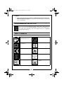
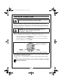
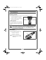
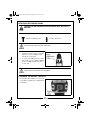
CON18LI.fm Page 1 Monday, September 3, 2012 4:29 PM
18V CORDLESS COMBI DRILL
MODEL NO: CON18LI
PART NO: 6479512
OPERATION & MAINTENANCE
INSTRUCTIONS
LS0912
CON18LI.fm Page 2 Monday, September 3, 2012 4:29 PM
INTRODUCTION
Thank you for purchasing this CLARKE 18V Cordless Combi Drill.
Before attempting to use this product, please read this manual thoroughly and
follow the instructions carefully. In doing so you will ensure the safety of yourself
and that of others around you, and you can look forward to your purchase
giving you long and satisfactory service.
GUARANTEE
This product is guaranteed against faulty manufacture for a period of 12
months from the date of purchase. Please keep your receipt which will be
required as proof of purchase.
This guarantee is invalid if the product is found to have been abused or
tampered with in any way, or not used for the purpose for which it was
intended.
Faulty goods should be returned to their place of purchase, no product can
be returned to us without prior permission.
This guarantee does not effect your statutory rights.
CARTON CONTENTS
The following items should be supplied in the carton. If any parts are missing or
damaged, please see your Clarke dealer.
1 x 18 Volt Cordless Drill
1 x Battery Charger
2 x Li-Ion Battery Packs
1 x 6.25 mm Hexagon Shank Magnetic Screwdriver Bit Holder
6 x 6.25 mm Hexagon Shank Screwdriver Bits: PZ1; PZ2; PH1; PH2; Slot 5mm;
Slot 6mm
6 x Drill Bits, 2, 2.5, 3, 4, 5 & 6 mm
I x Case
2
Parts & Service: 020 8988 7400 / E-mail: [email protected] or [email protected]
CON18LI.fm Page 3 Monday, September 3, 2012 4:29 PM
SAFETY PRECAUTIONS
WARNING: READ ALL INSTRUCTIONS. FAILURE TO FOLLOW ALL
INSTRUCTIONS LISTED BELOW MAY RESULT IN ELECTRIC SHOCK, FIRE AND/
OR SERIOUS INJURY. THE TERM “POWER TOOL” IN ALL WARNINGS LISTED
BELOW REFERS TO YOUR 18V CORDLESS COMBI DRILL.
1. WORK AREA
a. Keep work area clean and well lit. Cluttered and dark areas invite
accidents.
b. Do not operate power tools in explosive atmospheres, such as in the
presence of flammable liquids, gases or dust. Power tools create sparks
which may ignite the dust or fumes.
c. Keep children and bystanders away while operating a power tool.
Distractions can cause you to lose control.
2. ELECTRICAL SAFETY
a. Avoid body contact with earthed or grounded surfaces such as pipes,
radiators, ranges or refrigerators. There is an increased risk of electric
shock if your body is earthed or grounded.
b. Do not expose power tools to rain or wet conditions. Water entering a
power tool will increase the risk of electric shock.
c. When operating a power tool outdoors, use an extension cord suitable
for outdoor use. Use of a cord suitable for outdoor use reduces the risk
of electric shock.
3. PERSONAL SAFETY
a. Stay alert, watch what you are doing and use common sense when
operating a power tool. Do not use a power tool while you are tired or
under the influence of drugs, alcohol or medication. A moment of
inattention while operating power tools may result in personal injury.
b. Use safety equipment. Always wear eye protection. Safety equipment
such as dust mask, non-skid safety shoes, or hearing protection used for
appropriate conditions will reduce personal injuries.
c. Avoid accidental starting. Ensure the switch is in the off position before
connecting to the power supply.
d. Do not overreach. Keep proper footing and balance at all times. This
enables better control of the power tool in unexpected situations.
e. Dress properly. Do not wear loose clothing or jewellery. Keep your hair,
clothing and gloves away from moving parts. Loose clothes, jewellery or
long hair can be caught in moving parts.
3
Parts & Service: 020 8988 7400 / E-mail: [email protected] or [email protected]
CON18LI.fm Page 4 Monday, September 3, 2012 4:29 PM
4. POWER TOOL USE AND CARE
a. Do not force the power tool. Use the correct power tool for your
application. The correct power tool will do the job better and safer at
the rate which it was designed.
b. Do not use the power tool if the switch does not turn it on and off. Any
power tool that cannot be controlled with the switch is dangerous and
must be repaired.
c. Disconnect the battery before making any adjustments, changing
accessories, or storing power tools. Such preventive safety measures
reduce the risk of starting the power tool accidentally.
d. Store idle tools out of the reach of children and do not allow persons
unfamiliar with the power tool or these instructions to operate the power
tool. Power tools are dangerous in the hands of untrained users.
e. Maintain power tools. Check for misalignment or binding of moving
parts, breakage of parts and any other condition that may affect the
power tools operation. If damaged, have the power tool repaired
before use. Many accidents are caused by poorly maintained power
tools.
f. Keep cutting tools sharp and clean. Poorly maintained cutting tools with
sharp cutting edges are less likely to bind and are easier to control.
g. Use the power tool and accessories in accordance with these
instructions and in the manner intended for the particular type of power
tool, taking into account the working conditions and the work to be
performed. Use of the power tool for operations different from intended
could result in a hazardous situation.
5. BATTERY TOOL USE AND CARE
a. Recharge only with the charger specified by the manufacturer. A
charger that is suitable for one type of battery pack may create a risk of
fire when used with another battery pack.
b. Use power tools only with specifically designated battery packs. Use of
any other battery packs may create a risk of injury and fire.
c. When battery pack is not in use, keep it away from other metal objects,
like paper clips, coins, keys, nails, screws or other small metal objects,
that can make a connection from one terminal to another. Shorting the
battery terminals together may cause burns or a fire.
d. Under abusive conditions, liquid may be ejected from the battery;
avoid contact. If contact accidentally occurs, flush with water. If liquid
contacts eyes, additionally seek medical help. Liquid ejected from the
battery may cause irritation or burns.
4
Parts & Service: 020 8988 7400 / E-mail: [email protected] or [email protected]
CON18LI.fm Page 5 Monday, September 3, 2012 4:29 PM
6. SERVICE
a. Have your power tool serviced by a qualified repair person using only
identical replacement parts. This will ensure that the safety of the power
tool is maintained.
ENVIRONMENTAL PROTECTION
Recycle unwanted materials instead of disposing of them as waste.
All tools, accessories and packaging should be sorted, taken to a
recycling centre and disposed of in a manner which is compatible
with the environment.
SAFETY SYMBOLS
Read instruction
manual before use
Indoor Use Only
Class 2 Double
Insulated
Maximum Temperature
CE Mark
Do not Incinerate
Weee Symbol
Thermal Fuse Fitted
Isolating Transformer
Do not immerse in
water
5
Parts & Service: 020 8988 7400 / E-mail: [email protected] or [email protected]
CON18LI.fm Page 6 Monday, September 3, 2012 4:29 PM
ELECTRICAL CONNECTIONS
WARNING! Read these electrical safety instructions thoroughly
before connecting the product to the mains supply.
This product battery charger is provided with a standard 13 amp, 230 volt
(50Hz), BS 1363 plug, for connection to a standard, domestic electrical supply.
Should the plug need changing at any time, ensure that a plug of identical
specification is used.
WARNING! The wires in the power cable of this product are
coloured in accordance with the following code:
Blue = Neutral
Brown = Live
If the colours of the wires in the power cable of this product do not correspond
with the markings on the terminals of your plug, proceed as follows.
• The wire which is coloured Blue must be connected to the terminal
which is marked N or coloured Black.
• The wire which is coloured Brown must be connected to the terminal
which is marked L or coloured Red.
Plug must be BS1363/A approved.
Always fit a 5 Amp fuse.
Live
Neutral
(Brown)
(Blue)
Ensure that the outer sheath of the cable is firmly held by the clamp
We strongly recommend that this machine is connected to the mains supply
via a Residual Current Device (RCD)
If in any doubt, consult a qualified electrician. DO NOT attempt any repairs
yourself.
This symbol indicates that this is a Class II product, and does not require
an earth connection.
6
Parts & Service: 020 8988 7400 / E-mail: [email protected] or [email protected]
CON18LI.fm Page 7 Monday, September 3, 2012 4:29 PM
BATTERY CHARGING
WARNING: WHEN THE BATTERY IS REMOVED FROM THE TOOL AFTER USE, IT
MAY BE HOT. ALWAYS ALLOW TO COOL BEFORE RECHARGING. DO NOT
RECHARGE A HOT BATTERY.
• The battery pack must be charged before operating the drill.
• The battery should be charged at ambient air temperatures of
between -10oC and 40oC.
TO CHARGE THE BATTERY PACK, PROCEED AS FOLLOWS.
1. Connect the charger to the mains
supply.
• The green power indicator will
light up.
2. Slide the battery onto the battery
charger.
• The green power indicator will
go out and the red charging
LED will light up.
3. When the battery is fully charged, the red charging LED will go out and the
green power LED will light up.
4. Switch off the charger at the mains and remove the battery from the
charger.
NOTE: Whilst charging, the battery pack and charger may become warm.
This is normal and should be expected.
7
Parts & Service: 020 8988 7400 / E-mail: [email protected] or [email protected]
CON18LI.fm Page 8 Monday, September 3, 2012 4:29 PM
BEFORE USE
FITTING THE BATTERY
FIT THE BATTERY
1. Slide the battery pack onto the
base of the handle.
REMOVE THE BATTERY
1. Press and hold the release button
on top of the battery.
2. Slide the battery away from the
base of the handle.
INSERTING DRILL BITS, OR SCREWDRIVER BITS
WARNING: BEFORE REMOVING ANY BITS, MAKE SURE THAT THE
FORWARD/REVERSE SWITCH IS IN THE CENTRAL LOCKED OFF POSITION.
1. Grip the chuck collar and rotate
the front of the chuck in an anticlockwise direction.
2. Place the bit in the jaws as far as it
will go.
3. Grip the chuck collar and rotate
the chuck sleeve in a clockwise
direction until it grips the bit tightly.
8
Parts & Service: 020 8988 7400 / E-mail: [email protected] or [email protected]
CON18LI.fm Page 9 Monday, September 3, 2012 4:29 PM
ADJUSTMENTS
FORWARD/REVERSE
The forward/reverse switch is used to select the direction of rotation.
1. Use the forward/reverse switch to
select the direction of rotation.
2. Reverse should only be selected
when removing screws.
SAFETY LOCK OFF
The forward/reverse switch can be
used as the safety lock off button by
pushing it half way through the drill
body.
WARNING: ALWAYS LOCK THE TRIGGER SWITCH IN THE OFF POSITION
WHEN THE DRILL IS NOT BEING USED OR ADJUSTMENTS ARE BEING MADE
TO THE SPEED OR TORQUE SETTINGS. THIS IS AN IMPORTANT SAFETY
FEATURE AND MUST BE OBSERVED.
SPEED RANGE
Use the speed range selector to
select the range you want to use.
• Setting 1 - 0-350 rpm
• Setting 2 - 0-1250 rpm
NOTE: Only use the speed range
selector when the chuck is
stationary.
9
Parts & Service: 020 8988 7400 / E-mail: [email protected] or [email protected]
CON18LI.fm Page 10 Monday, September 3, 2012 4:29 PM
SELECTING THE DRILLING MODE
WARNING: DO NOT CHANGE THE DRILLING MODE WHILE THE CHUCK IS
ROTATING.
The drill is equipped with two drilling modes.
Hammer drilling mode
Rotary drill mode
CAUTION: WHEN IN THE HAMMER DRILLING MODE YOU SHOULD ONLY
USE MASONRY DRILL BITS (NOT SUPPLIED).
1. To select hammer action mode,
rotate the mode selector until the
hammer symbol is aligned with
the arrow on the drill.
2. To select the drilling mode, rotate
the mode selector until the drill bit
symbol, is aligned with the arrow
on the drill.
CAUTION: NEVER USE THE HAMMER MODE FOR DRILLING MATERIALS
OTHER THAN CONCRETE AND MASONRY.
CHECKING THE BATTERY CAPACITY
Press and hold the button on the rear
of the drill to display the charge left in
the battery.
10
Parts & Service: 020 8988 7400 / E-mail: [email protected] or [email protected]
CON18LI.fm Page 11 Monday, September 3, 2012 4:29 PM
TORQUE ADJUSTMENT
To select the correct torque setting for screwdriving:
1. Set the mode selector to 1.
2. Fit and tighten the first screw,
3. if the clutch starts to ratchet
before the screw is correctly
seated, rotate the mode selector
to a higher number until the
clutch ratchets only when the
head of the screw is flush with the
surface of the material.
CAUTION: DO NOT ADJUST THE MODE SELECTOR WHILE THE CHUCK IS
ROTATING.
OPERATING THE DRILL
1. Make sure that the forward/reverse switch is positioned in either the
forward, or reverse position. See page 9.
NOTE: The trigger will not operate if the direction control switch is in the
central position.
2. Squeeze the trigger.
• The drill will start.
• The speed can be increased by increasing the pressure on the
trigger up to the maximum speed (Setting 1 - 350 rpm, Setting 2 1250 rpm).
3. Release the trigger to stop the drill.
• The drill is fitted with an electric brake which stops the motor when
the trigger is released.
11
Parts & Service: 020 8988 7400 / E-mail: [email protected] or [email protected]
CON18LI.fm Page 12 Monday, September 3, 2012 4:29 PM
DRILLING TIPS
• Always use sharp, good quality drill bits. The performance of your drill
is dependant on the quality of the bits used.
• After drilling material to the full depth, do not simply pull out the drill
but maintain chuck rotation to ease withdrawal.
• Reduce the pressure on the drill bit when it is about to break through.
This will prevent the drill from jamming.
• If drilling a large hole, first drill a pilot hole using a smaller drill bit.
• Always apply pressure to your drill bit in a straight line and, where
possible, at right angles to the workpiece.
• When drilling holes or driving screws into walls, floors etc., always
make sure that there are no live electrical wires in the path of the bit.
• When drilling in metal, the materials being drilled can become hot.
To reduce overheating use a suitable cooling lubricant. No cooling
lubricant is necessary when drilling cast iron or brass as they should
be drilled dry.
• When drilling metal, the harder the metal the slower the drill speed.
Similarly, the bigger the drill bit the slower the speed.
• Always start drilling at a slow speed to prevent the drill from slipping
out of the pop mark or indent, gradually increasing speed until the
optimum cutting speed is achieved whilst maintaining a MODERATE
pressure ONLY. NEVER force the drill bit into the work. This will
overheat the tip and cause it to dull very quickly.
• To prevent the drill bit from slipping when starting to drill a hole in
metal, use a centre punch to make an indentation at the start point.
• When drilling in wood, clamp a piece of scrap wood to the
underside of the material to avoid splintering.
• Always drill directly in line with the bit. Do not use sideways
movement as this may damage the drill or cause the bit to break.
• Large holes should be drilled with wood augers, flat wood bits or
hole saws.
12
Parts & Service: 020 8988 7400 / E-mail: [email protected] or [email protected]
CON18LI.fm Page 13 Monday, September 3, 2012 4:29 PM
SCREWDRIVING TIPS
• Place the screwdriver bit in the head of the screw and apply light
pressure to the drill.
• If the screw head is not flush with the material, increase the torque
and start again.
• Make sure that the screwdriver bit is inserted straight and upright in
the screw head, or the screw may be damaged.
• When driving wood screws, pre-drill pilot holes to make driving easier
and to prevent splitting the material.
• Select the forward direction to drive screws in and reverse direction
to take them out.
MAINTENANCE AND SERVICING
WARNING: ALWAYS REMEMBER TO POSITION THE DIRECTION CONTROL
SWITCH IN THE CENTRAL LOCKED OFF POSITION AND REMOVE THE
BATTERY PACK, BEFORE CLEANING THE DRILL.
• After use, remove the drill or screwdriver bit, open the chuck jaws
and tap the side of the chuck to remove any dust, or chippings etc.
• Keep the cooling vents clear.
• Clean the motor housing with a soft cloth.
• Keep the handle clean and free from oil and grease.
• Keep the charger clean and free from dust and grease.
• Worn or damaged parts must be replaced by qualified personnel.
• There are no user serviceable parts inside the drill.
REMOVING THE CHUCK
1. Open the jaws as far as possible.
2. Using a cross head screwdriver (inserted, down through the jaws), remove
the securing screw. The screw has a LEFT HAND THREAD and must therefore
be turned CLOCKWISE.
3. Grasp the chuck and unscrew it from the drill in the normal manner, i.e., by
screwing it anticlockwise.
13
Parts & Service: 020 8988 7400 / E-mail: [email protected] or [email protected]
CON18LI.fm Page 14 Monday, September 3, 2012 4:29 PM
SPECIFICATIONS
Model Number
CON18LI
Part Number
6479512
Charger voltage
230V~50Hz
Battery voltage
18 volts (1500 mAh)
Charging time
1 hour
Keyless chuck capacity
0.8 mm -10 mm
Torque settings
22
No load speed
Setting 1 - 0 - 350 RPM
Setting 2 - 0 - 1250 RPM
Maximum Drilling Capacity:
Wood - 16 mm
Steel - 8 mm
Masonry - 10 mm
Sound Pressure Level
88dB LpA
Sound Power Level
99 dB LWA
Vibration Level
16.41 m/s2
Weight
3.35 kg
14
Parts & Service: 020 8988 7400 / E-mail: [email protected] or [email protected]
CON18LI.fm Page 15 Monday, September 3, 2012 4:29 PM
DECLARATION OF CONFORMITY
15
Parts & Service: 020 8988 7400 / E-mail: [email protected] or [email protected]
CON18LI.fm Page 16 Monday, September 3, 2012 4:29 PM