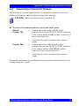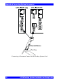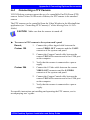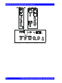
1
Conferencing Systems Escort/Cruiser Desktop Systems Installation and Setup Guide DOC01062 Rev. 5.0 10.04 © 2001, 2003, 2004 VCON Ltd. All Rights Reserved. Information in this document is subject to change without notice. No part of this document can be reproduced or transmitted in any form or by any means electronic or mechanical - for any purpose without written permission from VCON Ltd. MeetingPoint is a registered trademark of VCON, Inc., in the United States. VCON and Media Xchange Manager are trademarks of VCON Ltd. Microsoft and the Microsoft Internet Explorer logo are registered trademarks or trademarks of Microsoft Corporation in the United States and/or other countries. Windows and NetMeeting are trademarks of Microsoft Corporation. All other product names are trademarks or registered trademarks of their respective companies or organizations. CAUTION To comply with the limits for a Class A digital device, pursuant to Part 15 of the FCC Rules, the VCON system card must be connected to computer equipment certified to comply with Class A limits. All cables used to connect the computer and peripherals must be shielded and grounded. Operation with non-certified computers or non-shielded cables may result in interference to radio or television reception. Limited Warranty VCON Ltd. warrants the Product identified by the serial number indicated on the HARDWARE either accompanying the SOFTWARE or purchased separately will be free from defects in materials and workmanship under normal use and service for a period of ONE (1) year from the date of receipt. This Limited Warranty shall not apply to any product that in the opinion of VCON Ltd. has not been installed or upgraded according to accompanying documentation from VCON Ltd. or been subject to misuse, misapplication, negligence r accident while in the hands of the purchaser. VCON Ltd. warrants that SOFTWARE will perform according to accompanying user documentation for a period of 90 (ninety) days from the date of receipt; replacement SOFTWARE will be warranted for 90 (ninety) days from the date of receipt. ii VCON Desktop Systems Installation and Setup Guide GRANT OF LICENCE VCON Ltd. grants the Purchaser a non-exclusive and non-transferable license to use the SOFTWARE product and to make one copy solely for backup or archival purposes, which may include user documentation provided via online or other electronic form. Additional copies may not be made, nor may anyone else be allowed to copy or otherwise reproduce any part of the licensed software without prior written consent of VCON Ltd. COPYRIGHT All trademarks(s), logo(s), name(s), software, documentation and other supporting materials relating to the Product are trademarked, copyrighted or owned by VCON Ltd. as proprietary information protected by United States copyright laws and international and applicable national treaty provisions and laws. Software protection extends beyond its literal code to structure, sequence and organization; any unauthorized use or modification would constitute a misappropriation of VCON’s proprietary rights and a violation of the License agreement. LIABILITIES VCON’s entire liability and the Purchaser’s exclusive remedy shall be at VCON’s option, either return of the price paid or repair/replacement of the Product not meeting VCON’s declared Limited warranty. VCON or its suppliers shall not be liable in any event to anyone for any indirect, incidental, consequential, special or exemplary damages including without limitation damages for loss of business profits, business interruptions, business information or other pecuniary loss arising out of the use of or inability to use the said Product even if advised of the possibility of such damages. In any case, VCON’s entire liability under any provision of this agreement shall be limited to the amount actually paid by the Purchase for the Product. Modifications The FCC requires the user to be notified that any changes or modifications made to this device that are not expressly approved by VCON Ltd. may void the user’s authority to operate the equipment. VCON Desktop Systems Installation and Setup Guide iii Safety Notice The VCON system card should only be connected to and operated in SELV (Safety Extra Low Voltage) computers. The VCON system card should only be connected to computers that have a limited power source according to section 2.11 of the EN 60950 Safety Standard or to a computer that has a fire enclosure according to paragraph 4.4.6-4.4.8 of the EN 60950 Safety Standard. After being connected to the computer, only the external connectors should be accessible to users. The VCON Desktop system card must only be used in a computer that has a screwdown cover or lid. As unsafe voltages (TNV) exist on the card, disconnect the ISDN line from the card whenever the cover or lid of the computer is removed. There must be an air gap of at least 2mm. between the VCON Desktop system card and other components in the computer. iv VCON Desktop Systems Installation and Setup Guide For Users in Canada NOTICE: The Industry Canada Label identifies certified equipment. This certification means that the equipment meets telecommunications network protective, operational and safety requirements as prescribed in the appropriate Terminal equipment Technical Requirements document(s). The Department does not guarantee the equipment will operate to the user’s satisfaction. Before installing this equipment, users should ensure that it is permissible to be connected to the facilities of the local telecommunications company. The equipment must also be installed using an acceptable method of connection. The customer should be aware that compliance with the above conditions may not prevent degradation of service in some situations. Repairs to certified equipment should be coordinated by a representative designated by the supplier. Any repairs or alterations made by the user to this equipment, or equipment malfunctions, may give the telecommunications company cause to request the user to disconnect the equipment. Users should ensure for their own protection that the electrical ground connections of the power utility, telephone lines and internal metallic water pipe system, if present, are connected together. This precaution may be particularly important in rural areas. CAUTION Users should not attempt to make such connections themselves, but should contact the appropriate electric inspection authority, or electrician, as appropriate. NOTICE: The REN for this device is X.X. The Ringer Equivalence Number (REN) assigned to each terminal device provides an indication of the maximum number of terminals allowed to be connected to a telephone interface. The termination on an interface may consist of any combination of devices subject only to the requirement that the sum of the Ringer Equivalence Number of all the devices does not exceed 5. VCON Desktop Systems Installation and Setup Guide v Pour les utilisateurs au Canada AVIS: L’étiquette d’Industrie Canada identifie le matériel homologué. Cette étiquette certifie que le matériel est conforme aux normes de protection, d’exploitation et de sécurité des réseaux de télécommunications, comme le prescrivent les documents concernant les exigences techniques relatives au matériel terminal. Le Ministère n’assure toutefois pas que le matériel fonctionnera à la satisfaction de l’utilisateur. Avant d’installer ce matériel, l’utilisateur doit s’assurer qu’il est permis de le raccorder aux installations de l’entreprise locale de télécommunication. Le matériel doit également être installé en suivant une méthode acceptée de raccordement. L’abonné ne doit pas oublier qu’il est possible que la conformité aux conditions énoncées ci-dessus n’empêche pas la dégradation du service dans certaines situations. Les réparations de matériel homologué doivent être coordonnées par un représentant désigné par le fournisseur. L’entreprise de télécommunications peut demander à l’utilisateur de débrancher un appareil à la suite de réparations ou de modifications effectuées par l’utilisateur ou à cause de mauvais fonctionnnement. Pour sa propre protection, l’utilisateur doit s’assurer que tous les fils de mise à la terre de la source d’énergie électrique, des lignes téléphoniques et des canalisations d’eau métalliques, s’il y en a, sont raccordés ensemble. Cette précaution est particulièrement importante dans les régions rurales. AVERTISSEMENT L’utilisateur ne doit pas tenter de faire ces raccordements lui-même; il doit avoir recours à un service d’inspection des installations électriques, ou à un électricien, selons le cas. AVIS: Le IES assigné à cette équipment est X.X. L’indice d’équivalence de la sonnerie (IES) assigné à chaque dispositif terminal indique le mombre maximal de terminaux qui peuvent être raccordés à une interface. La terminaison d’une interface téléphonique peut consister en une combinaison de quelques dispositifs, à la seule condition que la somme d’indices d’équivalence de la sonnerie de tous les dispositifs n’excède pas 5. vi VCON Desktop Systems Installation and Setup Guide About this Installation and Setup Guide This Installation and Setup guide explains how to set up the VCON Desktop systems. The following chapter summary briefly describes this guide’s contents: Chapter 1 Chapter 2 Chapter 3 Chapter 4 Appendix A Welcome to VCON Videoconferencing Introduction to this Installation and Setup Guide System Installation and Connections Procedures for installing the system card and connecting the standard system equipment to your computer. MeetingPoint Setup Procedures for installing the MeetingPoint application and setting up its configuration. Troubleshooting Solutions for possible problems that you may encounter with the VCON system. Connecting Optional Accessories Procedures for connecting optional accessories and peripheral equipment to the VCON system. VCON Desktop Systems Installation and Setup Guide vii VCON Technical Support This Installation and Setup Guide was designed to help you prepare your videoconferencing system easily so that you can enjoy its many features. IIf a situation occurs that is not covered by the supplied documentation, contact your local VCON distributor, and request assistance from their VCON-trained technical support department. Please describe the problem, device, and PC operating system (if applicable), and any other relevant details. viii VCON Desktop Systems Installation and Setup Guide Table of Contents TABLE OF CONTENTS Limited Warranty ..............................................................................................ii Modifications................................................................................................... iii Safety Notice ....................................................................................................iv For Users in Canada ..........................................................................................v Pour les utilisateurs au Canada.........................................................................vi About this Installation and Setup Guide..........................................................vii VCON Technical Support ............................................................................. viii 1 Welcome to VCON Videoconferencing ............................................. 1 1.1 Desktop System Components ...................................................................2 Escort, Cruiser 150/384 Cards ..................................................................2 Desktop Camera........................................................................................4 Audio Devices...........................................................................................4 MeetingPoint Setup CD-ROM..................................................................5 Optional Accessories Supplied by VCON................................................5 2 System Installation and Connections ............................................... 7 2.1 Package Contents ......................................................................................7 2.2 Minimum System Requirements ..............................................................8 2.3 Desktop Systems Equipment Installation .................................................9 Installing the Videoconferencing Card ...................................................10 Connecting the ISDN Line (Cruiser 150/384) ........................................11 Connecting the Main Desktop Camera ...................................................12 Connecting the Telephone Handset (Escort, Cruiser 150) .....................13 Connecting Multimedia Speakers ...........................................................14 3 MeetingPoint Setup .......................................................................... 15 3.1 Uninstalling Previous MeetingPoint Versions........................................15 3.2 Installing MeetingPoint...........................................................................17 3.3 Starting and Exiting MeetingPoint® ......................................................25 System Managed by MXM.....................................................................25 Stand-alone System.................................................................................27 Exiting MeetingPoint ..............................................................................27 3.4 Setting Up The MeetingPoint Configuration..........................................28 3.5 Changing Configuration Information .....................................................41 VCON Desktop Systems Installation and Setup Guide ix Table of Contents 4 Troubleshooting................................................................................ 43 A Connecting Optional Accessories .................................................. 47 A.1 Connecting a Second Desktop Camera .................................................. 48 A.2 Connecting a VCR.................................................................................. 49 A.3 Connecting a Document Camera............................................................ 51 A.4 Connecting a PTZ Camera ..................................................................... 53 A.5 Connecting a Polycom SoundPoint PC 2-Way Speaker (Escort, Cruiser 150 only) ...................................................................... 55 A.6 Connecting a Tabletop Microphone (Cruiser 384 Executive Edition)............................................................. 56 x VCON Desktop Systems Installation and Setup Guide 1 WELCOME TO VCON VIDEOCONFERENCING Congratulations on your entry into the rapidly growing world of desktop videoconferencing! VCON’s desktop video meeting systems are sophisticated, yet friendly. They give you high video quality and powerful videoconferencing capabilities over an enterprise’s Internet Protocol (IP) local-area (LAN), wide-area networks (WAN) and Integrated Subscriber Digital Networks (ISDN). VCON systems meet all the technical requirements prescribed in the H.323 and H.320 ITU-T standards for networking. T The H.323 standard prescribes the worldwide-accepted recommendations for transmitting video, audio and data across IP LANs and WANs. T The H.320 standard prescribes the worldwide-accepted recommendations for transmitting video, audio and data over narrow-band ISDN digital telephone lines. The Escort provides an economical solution for enterprises that want to hold video meetings over their connected IP network. The Cruiser systems (150, 384) provide the ability to hold video meetings with other parties over both IP networks and ISDN lines. The standard VCON Desktop video meeting system includes a system PCI board, a camera, an audio handset or microphone, MeetingPoint software, and cables. Optional accessories such as additional cameras, multimedia speakers, and twoway speakers are also available. VCON Desktop Systems Installation and Setup Guide 1 Chapter 1 Welcome to VCON Videoconferencing 1.1 Desktop System Components All the components required for connecting and installing the Desktop Video Meeting system are supplied along with comprehensive documentation and powerful software to make your video meetings productive and enjoyable. The main standard Desktop system components are: • • • Videoconferencing PCI card • MeetingPoint setup CD-ROM Desktop camera Handset (Escort, Cruiser 150) 2 multimedia speakers (Cruiser 384) Escort, Cruiser 150/384 Cards T The Escort enables video meetings over IP networks only at a video transmit rate of up to 1.5 Mbps. It has connectors for the handset, multimedia speakers, line-level audio, main camera, and composite video. T The Cruiser 150 enables video meetings over IP networks at a video transmit rate of up to 1.5 Mbps, and over ISDN lines at up to 128 kbps (1-BRI). Each has a port for the ISDN connection, as well as connectors for a handset, multimedia speakers, line-level audio, main camera, and composite video. T The Cruiser 384 enables video meetings over IP networks at a video transmit rate of up to 1.5 Mbps, and over ISDN lines at up to 384 kbps (3-BRI). The card can process true wide-band audio. It has three ISDN ports, as well as: — Two audio inputs (microphone and line level) — Two audio outputs (primary and secondary) — Three video inputs (S-Video, primary composite, secondary composite) — Two video outputs (S-Video, composite). 2 VCON Desktop Systems Installation and Setup Guide Chapter 1 Welcome to VCON Videoconferencing Escort Cruiser 150 Front Panel Views VCON Desktop Systems Installation and Setup Guide Cruiser 384 3 Chapter 1 Welcome to VCON Videoconferencing Desktop Camera The desktop camera is handy for both an office environment and for portable use. It provides color video and includes a built-in microphone, focus, contrast, and other controls for adjusting the image manually. Desktop Camera Audio Devices Escort, Cruiser 150 Cruiser 384 For incoming and outgoing audio, these systems provide a handset with a telephone-like receiver for incoming and outgoing audio T For incoming audio, this system provides a pair of multimedia speakers. T For outgoing audio, the basic Cruiser 384 provides the desktop camera’s built-in microphone. The Cruiser 384 Executive Edition provides a tabletop microphone (see “Optional Accessories Supplied by VCON” on page 5). 4 VCON Desktop Systems Installation and Setup Guide Chapter 1 Welcome to VCON Videoconferencing MeetingPoint Setup CD-ROM The CD-ROM in the original VCON Desktop Video Meeting system package contains VCON’s conferencing application and online guides for setting up and operating your system. The CD-ROM includes: • • • MeetingPoint 4.6 or higher Microsoft Internet Explorer 5.0 (for viewing the online help) Online Product Guides — Desktop Systems Installation and Setup Guide — MeetingPoint User Guide Optional Accessories Supplied by VCON The following options may also be supplied by VCON as accessories for the Desktop Video Meeting system: Tabletop Microphone Document camera, PTZ camera A high-performance unidirectional audio source. It is highly sensitive, with a working range covering approximately 6 meters (20 feet) at an area greater than 180° from the front of the unit. Increases the video capabilities of the Desktop Video Meeting system. T A document camera shows a placed document on the screens of both parties during a conference. T A pan/tilt/zoom (PTZ) camera provides positioning capabilities and high-quality video. VCON Desktop Systems Installation and Setup Guide 5 2 SYSTEM INSTALLATION AND CONNECTIONS The VCON Desktop Video Meeting system installation includes the following stages: T Checking the items included in the shipping package T Verifying that your computer equipment matches the minimum requirements T Connecting the supplied equipment (for connection procedures of optional accessories, see Appendix A, “Connecting Optional Accessories”). 2.1 Package Contents When you open the VCON Desktop Video Meeting system shipping package for the first time, check that the following items are included, in accordance with the supplied product: Item Escort Cruiser 150 Cruiser 384 1 Videoconferencing PCI card 1 Philips NTSC or PAL desktop camera 1 telephone handset and cable N/A 2 multimedia speakers Opt Opt 1 ISDN cable N/A N/A 3 ISDN cables N/A N/A 1 Audio stereo cable Opt Opt 1 Camera control cable Opt Opt Opt 1 S-Video cable Opt Opt Opt 1 MeetingPoint setup CD-ROM 1 MeetingPoint User Guide 1 Warranty/ Registration card 2nd camera Opt Opt Opt Pan/Tilt/Zoom camera Opt Opt Opt VCON Desktop Systems Installation and Setup Guide 7 Chapter 2 System Installation and Connections Item Escort Cruiser 150 Cruiser 384 Polycom SoundPoint PC 2-way speaker Opt Opt Opt External Tabletop/Desktop Microphone N/A N/A Opt Legend: - Standard, Opt – Option, N/A – Not applicable. 2.2 Minimum System Requirements Before installing the VCON Desktop Video Meeting system, make sure that your computer equipment meets the following minimum requirements: T PC Pentium 200 MHz or higher T Any Ethernet Network Interface Card (for LAN/IP videoconferencing) T Windows 95/98 or Windows NT 4.0/2000 operating system with Microsoft TCP/IP installed T Microsoft Internet Explorer 4.0 (or later) installed. To view the online help, IE 4.0 (or later) must be your default web browser. If IE is not installed on your computer, you may install IE 5.0 from the MeetingPoint CD-ROM. T CD-ROM drive or access to a network CD-ROM drive T PCI bus interface T 32 MB RAM (for Windows 95/98-based computers) 64 MB RAM (for Windows NT/2000-based computers) T 50 MB free disk space T Mouse T SVGA monitor or projector T SVGA card supporting Direct Draw with minimum 2.5 MB memory. 8 VCON Desktop Systems Installation and Setup Guide Chapter 2 System Installation and Connections 2.3 Desktop Systems Equipment Installation This section describes how to connect the standard components of the VCON Desktop Video Meeting system. The following table lists the appropriate equipment installation procedures for each VCON desktop system and the page number on which you will find the procedure. Except for the first procedure, “Installing the Videoconferencing Card” you can perform the connections in any order that’s convenient. Procedure Escort Cruiser 150 Cruiser 384 N/A Connecting the Main Desktop Camera see page 12 Connecting the Telephone Handset (Escort, Cruiser 150) see page 13 N/A Opt Opt Installing the Videoconferencing Card, see page 10 Connecting the ISDN Line (Cruiser 150/384) see page 11 Connecting Multimedia Speakers see page 14 Legend: - Standard, Opt – Option, N/A – Not applicable. VCON Desktop Systems Installation and Setup Guide 9 Chapter 2 System Installation and Connections Installing the Videoconferencing Card The first procedure in the installation of the VCON Desktop Video Meeting system is the insertion of the system card into a free PCI slot (Cruiser 384 requires the space of two adjacent slots) in the computer. DANGER Before installing the videoconferencing card, turn off the computer and all attached equipment. Disconnect them from the power supply. ³ To install the videoconferencing card 1. Remove the computer’s cover. 2. Insert the supplied videoconferencing card into a free PCI slot and secure it in place by tightening the slot's retaining screw. 3. Replace the computer’s cover. Inserting the Videoconferencing Card 10 VCON Desktop Systems Installation and Setup Guide Chapter 2 System Installation and Connections Connecting the ISDN Line (Cruiser 150/384) The Cruiser 150 supports connection over one ISDN line, through a Basic Rate Interface (BRI) or two B-channels. If your card is a Cruiser 384, you can connect up to three ISDN lines (3-BRI or six B-channels). ³ To connect the videoconferencing card to an ISDN line Cruiser 150 Cruiser 384 T Connect an ISDN cable to the ISDN connector on the videoconferencing card’s panel. Cruiser 384 supports the connection of up to three ISDN lines. If you are going to receive incoming Bonding calls, the order of connection, as detailed below is important. T 1 BRI = 128 kbps connectivity. To use only one ISDN line, connect an ISDN cable to the ISDN 1 connector. T 2 BRI = 256 kbps connectivity. To use two ISDN lines, connect the first ISDN cable to the ISDN 1 connector and the second ISDN cable to the ISDN 2 connector. T 3 BRI = 384 kbps connectivity. To use three ISDN lines, connect the first ISDN cable to the ISDN 1 connector, the second ISDN cable to the ISDN 2 connector, and the third ISDN cable to the ISDN 3 connector. NOTE Verify that the NT1 ISDN Adapter, installed by your phone company or ISDN carrier, is connected and configured properly. VCON Desktop Systems Installation and Setup Guide 11 Chapter 2 System Installation and Connections Connecting the Main Desktop Camera As standard equipment, a desktop camera is provided with the VCON Desktop Video Meeting system. CAUTION Make sure that the camera is turned off. ³ To connect the main desktop camera to the Desktop Video Meeting system T Connect the camera’s mini-DIN cable connector to the CAM1 connector (for Cruiser 384, Desktop Camera) on the system card panel. Before inserting the cable, align the arrow mark on the cable connector with the breakage of the inner metal ring of the CAM1 (or Desktop Camera) connector of the card. Desktop Camera Connecting the Desktop Camera to the Desktop System Card 12 VCON Desktop Systems Installation and Setup Guide Chapter 2 System Installation and Connections Connecting the Telephone Handset (Escort, Cruiser 150) The Escort and Cruiser 150 support the use of a telephone handset as an audio source. ³ To connect the handset to the Desktop Video Meeting system T Connect the supplied handset or earpiece (optional) to the Handset connector on the system card panel. Connecting the Handset to the Desktop System Card VCON Desktop Systems Installation and Setup Guide 13 Chapter 2 System Installation and Connections Connecting Multimedia Speakers Multimedia speakers are supplied as standard equipment with Cruiser 384 systems. They may be provided as optional equipment with other VCON Desktop Videoconferencing systems. ³ To connect multimedia speakers to the Desktop Video Meeting system T Connect the speakers to the SPKRS connector on the system card’s panel. -orT If the speakers are connected to a Soundblaster™-compatible sound card, connect the audio cable between the Speakers connector on the system card’s panel and the Line In connector on the sound card. An additional audio stereo cable is included in the Cruiser 150 package as standard equipment, and may be included in the Escort and Cruiser 384 packages as an option. Connecting Multimedia Speakers to the Desktop System Card 14 VCON Desktop Systems Installation and Setup Guide 3 MEETINGPOINT SETUP After you finish installing the VCON Desktop Video Meeting system and accessories, install and set up the MeetingPoint software application. The MeetingPoint setup stages include: T Verifying that your computer equipment matches the minimum requirements (see “Minimum System Requirements” on page 8). T Uninstalling any previous version of MeetingPoint T Installing the new version of MeetingPoint T Setting up the MeetingPoint configuration. 3.1 Uninstalling Previous MeetingPoint Versions If a previous version of MeetingPoint is currently installed on the computer, uninstall it completely. The Uninstall program deletes all previous MeetingPoint information and files. However, the program provides the options of saving setup information and the existing address book entries, which may shorten the process of setting up MeetingPoint. The Uninstall procedure depends on the previous MeetingPoint version: • • MeetingPoint 2.66 or earlier MeetingPoint 3.0 or later. ³ To delete the previous MeetingPoint version T If the previous version is MeetingPoint 2.66 or earlier 1. In the Windows desktop, click Start, point to Programs and MeetingPoint, and then click Uninstall MeetingPoint. The MeetingPoint Uninstall Wizard opens. 2. Perform the instructions on the screen. When the Uninstall process is complete, restart the computer. VCON Desktop Systems Installation and Setup Guide 15 Chapter 3 MeetingPoint Setup T If the previous version is MeetingPoint 3.0 or later 1. In the Windows desktop, click Start, point to Settings and then click Control Panel. The Control Panel window appears. Windows Control Panel 2. Double-click Add/Remove Programs. The Add/Remove Programs Properties dialog box appears. Add/Remove Programs Dialog Box 16 VCON Desktop Systems Installation and Setup Guide Chapter 3 MeetingPoint Setup 3. Click VCON Meeting Point x.x and then click Add/Remove. The MeetingPoint Uninstall Wizard opens. 4. Perform the instructions on the screen. When the Uninstall process is complete, restart the computer. 3.2 Installing MeetingPoint To communicate using MeetingPoint, TCP/IP protocol components must be installed on your computer. If necessary, install them before installing MeetingPoint. Consult with your system administrator. The supplied MeetingPoint CD-ROM contains the Setup program for installing MeetingPoint. ³ To install MeetingPoint on your computer 1. Close all open applications. 2. Insert the MeetingPoint CD-ROM into the computer’s CD-ROM drive. After you close the drive door, the MeetingPoint Installation Utility appears (see the figures on the next page). If the Installation Utility window does not appear, click Start at the lower left corner of the Windows desktop. Click Run to open the Run dialog box. Locate and select the install application file on the CD-ROM drive and click Open. In the Run dialog box, click OK VCON Desktop Systems Installation and Setup Guide 17 Chapter 3 MeetingPoint Setup MeetingPoint Installation Utility Window 3. Click Install MeetingPoint to start the MeetingPoint installation process. If it’s not already in your computer, Microsoft NetMeeting will also be installed. A message then asks if your system will register to a VCON Media Xchange Manager™ (MXM) system. If your system is managed by an MXM, telephony exchange functions such as Call Forwarding, Call Pickup, Call Transfer and Ad-hoc Conferencing are available. MXM Management Question 18 VCON Desktop Systems Installation and Setup Guide Chapter 3 MeetingPoint Setup 4. Click Yes or No, accordingly, to continue. If asked if you are sure if you want MXM management, click Yes again to install an MXM-managed version. If your computer requires, Setup installs Microsoft Direct-X drivers and then Microsoft NetMeeting™ (version 3.01 for Escort users or 2.1 for Cruiser users). The Welcome screen appears. Welcome Window VCON Desktop Systems Installation and Setup Guide 19 Chapter 3 MeetingPoint Setup 5. Click Next. The User Information dialog box appears. User Information Dialog Box 6. Type your Name and Company name. The product’s license number appears automatically in the Serial box. Click Next. The Software License Agreement appears. Software License Agreement 20 VCON Desktop Systems Installation and Setup Guide Chapter 3 MeetingPoint Setup 7. Read the terms and conditions in the software license agreement carefully. — To accept the terms and conditions in the license agreement, click Yes to continue the installation. The Language Options dialog box appears. — To reject the terms, click No. The installation process ends. Choosing Application Language VCON Desktop Systems Installation and Setup Guide 21 Chapter 3 MeetingPoint Setup 8. Choose the language of your MeetingPoint application. Click Next. The Choose Destination Location dialog box appears. Choose Destination Location Dialog Box 9. The MeetingPoint program will be installed to the default folder. If you want to install MeetingPoint in a different folder, click Browse. In the Choose folder dialog box, select a different location and click OK. The Start Copying Files dialog box appears. Start Copying Files Dialog Box 22 VCON Desktop Systems Installation and Setup Guide Chapter 3 MeetingPoint Setup 10. In the Start Copying Files dialog box, check and confirm your settings. — To change any incorrect settings, click Back as many times as necessary to open the appropriate dialog box. — Otherwise, click Next to continue. The installation program copies the MeetingPoint files to the destination folder on the hard disk. The progress of the installation is shown. MeetingPoint Installation Progress Updating the MeetingPoint Registry VCON Desktop Systems Installation and Setup Guide 23 Chapter 3 MeetingPoint Setup At the end of the installation, the Setup Complete dialog box appears. Setup Complete Dialog Box 11. To start MeetingPoint for the first time, you must restart the computer. Select Yes if you want to restart the computer now or select No if you want to continue with another activity and restart the computer later. Click Finish to implement your selection and close the Installation program. 24 VCON Desktop Systems Installation and Setup Guide Chapter 3 MeetingPoint Setup Starting and Exiting MeetingPoint® 3.3 MeetingPoint’s Start procedure varies, depending on whether or not your system will be in a videoconferencing network managed by a VCON Media Xchange Manager™ (MXM). System Managed by MXM ³ To start MeetingPoint 1. In the Windows Desktop, click the VCON MeetingPoint icon. The Login dialog box appears. Initial Login to MXM 2. Enter MXM login information as follows (consult with your system administrator): MXM Login Name Password/ Verify Password Gatekeeper 3. The name of your computer as listed in the MXM database and the MXM Administrator. Password required to log in. The first time you register, you must type it twice for verification. If you do not supply this password, the login request is rejected. The IP address of the MXM. If you do not know it, ask your system administrator. Click Connect to complete the login process. — If the MXM automatically registers your computer, the MeetingPoint application opens. — If a message appears stating that the MeetingPoint startup cannot proceed until login is granted, contact your system administrator. After login is granted, click Connect to continue. VCON Desktop Systems Installation and Setup Guide 25 Chapter 3 MeetingPoint Setup If you are running MeetingPoint for the first time after installation (or logging into a different MXM), the Configuration Wizard setup program appears. This program asks you to enter the information required to run MeetingPoint from your specific location. For the complete standard setup procedure, see “Setting Up The MeetingPoint Configuration” on page 28. MeetingPoint’s default properties are suitable for most video meeting requirements. If you must change these settings, please consult with your system administrator or VCON distributor. At this point, if the system’s communication lines are connected, you may start a video meeting and receive incoming video meeting calls. Conference Panel(MXM Support) and Local Video Window 26 VCON Desktop Systems Installation and Setup Guide Chapter 3 MeetingPoint Setup Stand-alone System ³ To start MeetingPoint 1. In the Windows Desktop, click the VCON MeetingPoint icon. The Conference Panel appears, followed by the Local Video window. If you are running MeetingPoint for the first time after installation, the Configuration Wizard setup program appears. This program asks you to enter the information required to run MeetingPoint from your specific location. For the complete standard setup procedure, see see “Setting Up The MeetingPoint Configuration” on page 28. MeetingPoint’s default properties are suitable for most video meeting requirements. If you must change these settings, please consult with your system administrator or VCON distributor. At this point, if the system’s communication lines are connected, you may start a video meeting and receive incoming video meeting calls. Conference Panel - Stand-alone MeetingPoint Exiting MeetingPoint ³ To exit MeetingPoint T Double-click the MeetingPoint icon at the far left side of the Conference Panel. -orRight-click anywhere in the Conference Panel and click Exit. If you are connected in a video meeting, a message asks you to hang up before you exit MeetingPoint. VCON Desktop Systems Installation and Setup Guide 27 Chapter 3 MeetingPoint Setup 3.4 Setting Up The MeetingPoint Configuration This section provides procedures for setting up MeetingPoint according to your particular specifications. As instructed in the previous section, you must restart the computer after installing MeetingPoint in order to run it for the first time. The Configuration Wizard guides you through the required stages and requests the relevant information for normal operation of MeetingPoint. In addition, you may change any of these configuration details (as long as they are compatible with your equipment) whenever the system is on. The Properties command is available: T The Conference Panel’s shortcut menu. Right-click to open it. T The Conference Panel button menus. Click any arrow to open a specific menu for each MeetingPoint application. T In particular windows and dialog boxes. Configuration Wizard Introduction ³ To set up the MeetingPoint configuration 1. 28 From the Configuration Wizard’s opening page, click Next to continue. The User Information dialog box appears. VCON Desktop Systems Installation and Setup Guide Chapter 3 MeetingPoint Setup 2. In the User information section, type your First Name, Last Name, Company name, and E-mail address. User Information Configuration Cruiser 150/384 only In the Dialing Information section, click the Country that you are in, type your area code, and type the appropriate digits for dialing an outside line (External), a Long Distance call, or an International call. If you need to dial a specific digit to receive an external line, you must type that digit before the digits required for a long distance or international call. For example, if you have to dial 9 to receive an external line, and then 01 to dial long distance, type 901 in the Long Distance box. Click Next to continue. — If your Desktop system card is Escort, the LAN dialog box appears. Proceed directly to step 7. — If your Desktop system card is Cruiser 150 or Cruiser 384, the Connection dialog box appears. VCON Desktop Systems Installation and Setup Guide 29 Chapter 3 MeetingPoint Setup 3. In the Communication list, select the type of external communication line your system will use. Connection Dialog Box None On Board ISDN Select for using MeetingPoint with a LAN connection only. Select for using MeetingPoint with an ISDN line through the Desktop system card, in addition to a LAN connection. Click Next to continue. — If you selected None, the LAN dialog box appears. Proceed directly to step 7. — If you selected On Board ISDN, the Switch Type dialog box appears. 30 VCON Desktop Systems Installation and Setup Guide Chapter 3 MeetingPoint Setup 4. In the Switch Type dialog box, the country you are in already appears as Your Location (set in the User Information dialog box in step 2). Switch Type Dialog Box In the Switch Type list, the most common switch type for your country appears automatically. If you are using a different switch type (according to your ISDN carrier), click a different switch type: • • • • AT&T 5ESS Custom National ISDN 1 NT DMS100 Custom Japanese NTT • • • • German 1TR6 French VN3 Australian TS013 Euro-ISDN NET3 In certain areas of the United States, the main ISDN network is Restricted (data rate of 56K). If the computer is connected to a Restricted network, select Check this box if you have restricted 56K access. If you are not sure whether the computer is connected to a Restricted network, do not select this option. If necessary, consult with your system administrator or ISDN carrier. Click Next to continue. The Phone Numbers dialog box appears. VCON Desktop Systems Installation and Setup Guide 31 Chapter 3 MeetingPoint Setup 5. In the Phone Numbers dialog box, enter your ISDN phone numbers. ISDN Phone Numbers Configuration Select the number of ISDN phone lines you will be using Click the number of ISDN lines the system uses. The number of available lines depends on the number of BRIs (Basic Rate Interface) on the videoconferencing card. Each BRI supports up to two phone lines of 64 kbps each (56 kbps in Restricted networks): T Cruiser 150 – Up to 2 ISDN lines (1 BRI) T Cruiser 384 – Up to 6 ISDN lines (3 BRI). Phone Numbers In the Phone numbers boxes, type the ISDN numbers of each line. Do not include your own country’s international code or your local area code. If your ISDN carrier supplied you two identical phone numbers for a BRI, type the number in the consecutive boxes (#1, #3, #5). In all other cases, the phone numbers for each ISDN line may be different. Click Next to continue. — If you selected switch type AT&T 5ESS Custom, National ISDN 1 or NT DMS100 Custom, the SPID Numbers dialog box appears. — Otherwise, the LAN dialog box appears. Proceed directly to step 7. 32 VCON Desktop Systems Installation and Setup Guide Chapter 3 MeetingPoint Setup 6. If your ISDN carrier supplies you with SPID (Service Profile Identifier) numbers, you have to enter them in the SPID Numbers dialog box. A SPID number describes the capabilities of each computer or phone on the ISDN lines. This information may be important to your local telephone company in defining the level of service to provide. If necessary, obtain this information from your ISDN carrier. SPID Numbers Configuration Enter SPID Numbers information as follows: Number of SPIDs Click the amount of SPID numbers that you have. SPID 1,2,3,4,5,6 Type the SPID numbers. If the SPID numbers for each line are identical, or you received only one SPID number from your ISDN carrier, type that number in the SPID 1 box. If you did not receive a SPID number, leave the SPID boxes blank. Click Next to continue. The LAN dialog box appears. VCON Desktop Systems Installation and Setup Guide 33 Chapter 3 MeetingPoint Setup 7. In the LAN dialog box, enter configuration information for holding video meetings over the connected network. LAN Connection Configuration The LAN configuration includes: User Name The user’s unique name on the connected network (H.323 alias). User Number The user’s unique logical number (E.164 string) as defined by your network’s system administrator. The User Number must consist of digits only. For example, it could be the same as your phone extension, so that others can remember it. Gatekeeper Address 34 The IP address of the MXM or H.323 Gatekeeper to which the computer will register. This information is optional. However, if your organization has installed a gatekeeper, we recommend that you enter its address. If you do not know its address, ask your system administrator. VCON Desktop Systems Installation and Setup Guide Chapter 3 MeetingPoint Setup If you leave this box blank, the computer cannot register with a gatekeeper. CAUTION If you want to register a stand-alone system in an MXM, you must uninstall MeetingPoint and then define this request during the new MeetingPoint installation. Do not type the address of the MXM in this space. Allow Adaptive Bandwidth Adjustment Select this option to enable reduction of the alloted bandwidth if the network is congested. Enable Lip Synchronization Mechanization Select this option to enable adjustment of the video and the audio if they are out of sync with each other (see the MeetingPoint 4.6 User Guide, Appendix B, “Monitoring the Conference State”). Automatic Buffering Control T Select this option to enable the system to automatically control the amount of buffering required to maintain the consistency of the video and audio transmission. For example, if video packets are delayed for 1 or 2 seconds, the system will automatically synchronize the transmission so that the delay does not disturb the visible video. T Deselect this option only if the automatic buffering is not sufficient — for example, if the quality of the video meeting is poor or there is a noticeable delay. Click Next to continue. — If this version does not support MXM, the Online Directories dialog box appears. — Otherwise, the Pan/ Tilt/Zoom Camera appears. Proceed directly to step 9. VCON Desktop Systems Installation and Setup Guide 35 Chapter 3 MeetingPoint Setup 8. In the Online Directories dialog box, specify if you want to register with an online directory, and if so, which one. Online directories contain lists of registered Internet users who are currently connected to the Internet (online). These directories are usually located on Internet Location Servers (ILS). By default, MeetingPoint enables you to register in the same ILS as other VCON videoconferencing users, ils.vcon.co.il. Online Directories Dialog Box Enter Online Directories information as follows: Online Directories Select Register with and Display Online Directories if you want to display an online directory in the MeetingPoint Address Book. Online Directory Server In the Server Name list, select the name of the server that you want to register with when you are online. Click Next to continue. The Pan/ Tilt/Zoom Camera dialog box appears. 36 VCON Desktop Systems Installation and Setup Guide Chapter 3 MeetingPoint Setup 9. The Pan/ Tilt /Zoom Camera dialog box is applicable if you connected a Pan/Tilt/Zoom-type (PTZ) camera to the computer. If you do not use a PTZ camera, you can select None as the PTZ camera type in the dialog box’s top list and continue the MeetingPoint setup. Pan/Tilt/Zoom Camera Configuration Dialog Box Enter information as follows: Camera Selection In the Select your Pan/Tilt/Zoom camera type list, select the manufacturer and/or model of the PTZ camera. If you do not use a PTZ camera, keep the default value None. In the Select the communication port it is connected to list, select the name of the computer port to which the camera is connected. The available options are COM1, COM2, COM3 and COM4. VCON Desktop Systems Installation and Setup Guide 37 Chapter 3 MeetingPoint Setup Camera Control T Select Allow the remote side to control camera settings to permit the remote party to control the position and video settings of your PTZ camera. If you do not have a PTZ camera, this option is not relevant. Click Next to continue. — If your videoconferencing card is an Escort, the Confirmation dialog box appears. Proceed directly to step 12. — If your videoconferencing card is a Cruiser 150 or Cruiser 384, the MSN dialog box appears. 10. If the connected ISDN network supports Multiple Subscriber Numbering (MSN), you can specify whether you want to use this feature or not. The MSN service provides more than one phone number per ISDN line. This enables you to connect several phones, faxes, modems, and/or other devices to their own individual phone numbers over a single ISDN line. MSN Configuration 38 VCON Desktop Systems Installation and Setup Guide Chapter 3 MeetingPoint Setup Enter MSN information as follows: MSN Support T Select Yes to use MSN capabilities. When MeetingPoint opens after this setup process, you will be able to specify the exact MSN numbers for the computer in the MSN tab of the Conference Panel Configuration Properties dialog box. T Select No if the connected ISDN network does not support this feature, or if you don’t want to use it. Click Next to continue. The Sub-Addressing dialog box appears. 11. The Sub-Addressing dialog box is applicable if the computer shares an ISDN BRI line with other equipment (such as other computers, fax machines, standard telephones, and so on). In such a case, the computer has an additional series of numbers and/or letters added to the end of its phone number. Sub-Addressing Dialog Box VCON Desktop Systems Installation and Setup Guide 39 Chapter 3 MeetingPoint Setup If the computer has a sub-address, enter information as follows: Sub-Addressing Type the phone number followed by an “¦” character, and the series of numbers and/or letters making up the sub-address. If the connected ISDN network does not support this feature, or if you do not want to use it, leave this box blank. Click Next to continue. The Confirmation dialog box appears. 12. In the Confirmation dialog box, review the information that you entered during the MeetingPoint setup process. If necessary, drag the scroll bar down to see more information. Confirmation of Setup Information To change any information before exiting the MeetingPoint Configuration Setup Wizard, click Back to return to a specific dialog box and make the appropriate changes. When you are finished, click Next as many times as necessary to return to the Confirmation dialog box and check your settings again. 40 VCON Desktop Systems Installation and Setup Guide Chapter 3 MeetingPoint Setup 13. To save the setup and exit the Configuration Setup Wizard, click Finish. The MeetingPoint program now starts, and the Conference Panel and the Local Video Window appear. To cancel the setup, click Cancel. In this case, all setup information will be discarded and you will not be able to run MeetingPoint until you perform the setup at another time. 3.5 Changing Configuration Information After completing the Configuration Wizard the first time that you run MeetingPoint, you can change the configuration information through the System Properties dialog boxes. The System Properties are accessible from several locations. The table below describes the quickest way to access the configuration information that you entered in the Configuration Wizard. User Information In the Conference Panel, right-click and then click Properties. In the Properties dialog box, click the User Data icon. LAN T Double-click the Gatekeeper icon in the Conference Panel tray. or -orT MXM-managed applications only In the Conference Panel, click the Network arrow and then click H.323 Properties. If the system is not registered with a GateKeeper: Online Directories T In the Conference Panel, right-click and then click Properties. In the Properties dialog box, click the Communication icon. Non-MXM applications only 1. In the Conference Panel, click the Dialer arrow and then click Properties. The Address Book Properties dialog box appears with the General tab open. 2. Click the Online Directories tab. VCON Desktop Systems Installation and Setup Guide 41 Chapter 3 MeetingPoint Setup Pan/Tilt/Zoom Switch Type, Phone Numbers, SPID, MSN, Subaddressing 42 1. In the Conference Panel, right-click and then click Properties. In the Properties dialog box, click the Hardware icon. 2. 1. Click the Camera tab. In the Conference Panel, right-click and then click Properties. In the Properties dialog box, click the Telephony icon. 2. Click the appropriate tab. VCON Desktop Systems Installation and Setup Guide 4 TROUBLESHOOTING This chapter provides solutions for common oversights and issues. If you cannot find a solution to a problem, call your local VCON service provider. PROBLEM: The MeetingPoint application fails to open. A message states that the system cannot initialize. SOLUTIONS: 1. Check that Plug and Play is enabled in the computer. In the Windows Control Panel, click System and then Device Manager. Check that the USB Root Hub is enabled and working in the device. If not, restart the computer and enable Plug and Play in the BIOS. Consult with your system administrator. 2. In the Windows Control Panel, click Add New Hardware. Browse for dvs.inf (for Windows 95/98) or dvs2000.inf (for Windows 2000) on the MeetingPoint CD-ROM. This file contains MeetingPoint setup information. Click OK to install. 3. Insert the VCON videoconferencing card in a different PCI slot in your computer. PROBLEM: The Local Video window is blank. SOLUTION: T Check that the cable is correctly connected between the camera and the VCON videoconferencing card. PROBLEM: The Local Video window is black. SOLUTION: 1. Check that the power switch on the camera is ON. 2. In the Local Video window, click the Select Camera button. Select a different camera option. VCON Desktop Systems Installation and Setup Guide 43 Chapter 4 Troubleshooting PROBLEM: The video quality is poor. SOLUTION: 1. Make sure that your computer meets the minimum requirements (see “Minimum System Requirements” on page 8). 2. Adjust the focus of the camera manually. PROBLEM: An optional Pan/Tilt/Zoom camera is connected, but your system is not using it. SOLUTION: 1. In the Local Video window, click the Select Camera button. Check that you selected the PTZ camera. 2. In MeetingPoint’s Conference Panel, right-click and then click Properties. In the Hardware Properties, click the Camera tab. Check that you selected the appropriate PTZ camera type and communication port. 3. Check that the camera cables are securely connected to the ViGO’s Video connector and the computer’s COM port. PROBLEM: The remote side cannot hear you. SOLUTION: 1. In MeetingPoint’s Conference Panel, right-click and then click Properties. In the Hardware Properties, click the Audio tab. Check that you selected the appropriate audio device. 2. Make sure that the audio device is correctly connected to the videoconferencing card. 3. Check if Mute Microphone is active. If so, disable muting. 44 VCON Desktop Systems Installation and Setup Guide Chapter 4 Troubleshooting PROBLEM: You cannot hear the remote side. SOLUTION: 1. In the Remote Video window, click the Volume Control right arrow button to increase volume. 2. Make sure that the incoming audio device’s cable is firmly inserted into the SPKR connector on the VCON system card. 3. In MeetingPoint’s Conference Panel, right-click and then click Properties. In the Hardware Properties, click the Audio tab. Make sure that the correct audio device or speaker is selected. PROBLEM: Attempts to establish data sharing were unsuccessful. SOLUTION: T Check that the applicable version of Microsoft® NetMeeting™ is installed on your system (NetMeeting may be installed during MeetingPoint installation). — If your video meeting system is Escort, NetMeeting 3.01 is applicable. — If your video meeting system is Cruiser 150, NetMeeting 2.1 is applicable. If necessary, reinstall MeetingPoint and make sure that the program installs the appropriate version of NetMeeting. PROBLEM: The Interactive Multicast features are not available for Cruiser 150. SOLUTION: T Interactive Multicast is an optional feature for Cruiser 150 systems. If you want to add this option to your system, contact your local distributor. VCON Desktop Systems Installation and Setup Guide 45 A CONNECTING OPTIONAL ACCESSORIES In addition to its standard components, the VCON Desktop Video Meeting system is compatible with various optional accessories and peripheral devices that add features and convenience to your conferencing. This appendix explains how to connect these devices: • • • • • Connecting a Second Desktop Camera • Connecting a Tabletop Microphone (Cruiser 384 Executive Edition) Connecting a VCR Connecting a Document Camera Connecting a PTZ Camera Connecting a Polycom SoundPoint PC 2-Way Speaker (Escort, Cruiser 150 only) VCON Desktop Systems Installation and Setup Guide 47 Appendix A Connecting Optional Accessories A.1 Connecting a Second Desktop Camera VCON Desktop systems support the use of a second desktop camera as a video source. CAUTION Make sure that the computer and the camera are turned off. ³ To connect a second desktop camera to the Desktop Video Meeting system Escort, Cruiser 150 Cruiser 384 1. Connect the camera cable to the CAM 2 (yellow) connector of the system card panel. 2. Verify that the camera is connected to a power supply. Connect the camera cable to the VCR VID IN (yellow) connector of the system card panel. 1. 2. Verify that the camera is connected to a power supply. Connecting a Second Desktop Camera to the Desktop System Card 48 VCON Desktop Systems Installation and Setup Guide Appendix A Connecting Optional Accessories A.2 Connecting a VCR VCON Desktop systems support playback of a videocassette to a videoconference. CAUTION Make sure that the VCR is turned off. ³ To connect a VCR to the Desktop Video Meeting system for playback Escort, Cruiser 150 Cruiser 384 1. Connect the VCR Video cable with the jacks between the VIDEO OUT connector of the VCR and the CAM 2 (yellow) connector of the system card panel. 2. Connect the VCR cable with the jacks between the AUDIO OUT connector of the VCR and the AUD IN (white) connector of the system card panel. 3. 1. Verify that the VCR is connected to a power supply. Connect the VCR cable with the jacks between the VIDEO OUT connector of the VCR and the VCR VID IN (yellow) connector of the system card panel. 2. Connect the VCR cable with the jacks between the AUDIO OUT connector of the VCR and the VCR AUD IN (white) connector of the system card panel. 3. Verify that the VCR is connected to a power supply. For specific instructions on installing and operating the VCR, see its accompanying user’s guide. VCON Desktop Systems Installation and Setup Guide 49 Appendix A Connecting Optional Accessories Connecting a VCR to the Desktop System Card for Playback 50 VCON Desktop Systems Installation and Setup Guide Appendix A Connecting Optional Accessories A.3 Connecting a Document Camera VCON Desktop systems support the use of a document camera as a source for displaying documents and illustrations during video meetings. CAUTION Make sure that the camera is turned off. ³ To connect a document camera to the system card’s panel Escort, Cruiser 150 Cruiser 384 1. Connect the camera cable with the yellow connector between the OUTPUT/VIDEO connector of the camera and the CAM 2 (yellow) connector of the system card panel. 2. Verify that the camera is connected to a power supply. Connect the camera cable with the yellow connector between the OUTPUT/VIDEO connector of the camera and the VCR VID IN (yellow) connector of the system card panel. 1. 2. Verify that the camera is connected to a power supply. For specific instructions on installing and operating the document camera, see its accompanying user’s guide. VCON Desktop Systems Installation and Setup Guide 51 Appendix A Connecting Optional Accessories Connecting a Document Camera to the Desktop System Card 52 VCON Desktop Systems Installation and Setup Guide Appendix A Connecting Optional Accessories A.4 Connecting a PTZ Camera VCON Desktop systems support the use of a controllable Pan/Tilt/Zoom (PTZ) camera. In the Cruiser 384 Executive Edition, the PTZ camera is the standard camera. The PTZ camera can be controlled from the Video Window in the MeetingPoint application (see “Controlling PTZ Camera(s)” of the MeetingPoint 4.6 User Guide). CAUTION Make sure that the camera is turned off. ³ To connect a PTZ camera to the system card’s panel Escort, Cruiser 150 Cruiser 384 1. Connect the yellow-tipped cable between the camera VIDEO OUT connector and the CAM 2 connector of the system card panel. 2. Connect the Camera Control cable between the camera VISCA IN connector and a free COM port on the computer. 3. Verify that the camera is connected to a power supply. Connect the S-Video cable between the camera VIDEO OUT connector and the S-VIDEO connector of the system card panel. 1. 2. Connect the Camera Control cable between the camera VISCA IN connector and a free COM port on the computer. 3. Verify that the camera is connected to a power supply. For specific instructions on installing and operating the PTZ camera, see its accompanying user’s guide. VCON Desktop Systems Installation and Setup Guide 53 Appendix A Connecting Optional Accessories Connecting a PTZ Camera to the Desktop System Card 54 VCON Desktop Systems Installation and Setup Guide Appendix A Connecting Optional Accessories A.5 Connecting a Polycom SoundPoint PC 2-Way Speaker (Escort, Cruiser 150 only) Instead of the supplied handset, you may use a Polycom SoundPoint PC 2-way speaker system to improve the audio quality of video meetings, while freeing your hands for other tasks. This accessory is supported only by the Escort and Cruiser 150. CAUTION Make sure that the speaker is turned off. ³ To connect a SoundPoint PC system to the system card’s panel T Connect the SoundPoint PC double-sided RJ-11 cable between the SoundPoint console’s TO COMPUTER connector and the HANDSET connector of the system card panel. For specific instructions on installing and operating the Polycom Soundpoint PC system, see its accompanying user’s guide. Connecting the 2-way Speaker to the Desktop System Card VCON Desktop Systems Installation and Setup Guide 55 Appendix A Connecting Optional Accessories A.6 Connecting a Tabletop Microphone (Cruiser 384 Executive Edition) The Cruiser 384 Executive Edition includes a tabletop microphone. If more than one person will participate from the local side during the same conferences, a tabletop microphone is more efficient for sending out audio.. ³ To connect the tabletop microphone to the Cruiser 384 panel T Connect the microphone’s stereo jack to the card’s MIC connector. Connecting a Tabletop Microphone to the Cruiser 384 Card 56 VCON Desktop Systems Installation and Setup Guide