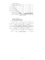
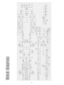
1
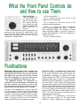
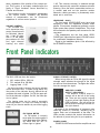
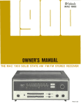
THE MCINTOSH MAC 4100 RECEIVER
Reading Time: 48 Minutes
Price $2.00
VARIOUS REGULATORY AGENCIES REQUIRE THAT WE BRING THE FOLLOWING INFORMATION TO YOUR ATTENTION. PLEASE READ IT CAREFULLY.
WARNING: TO PREVENT FIRE OR SHOCK
HAZARD, DO NOT EXPOSE THIS UNIT TO
RAIN OR MOISTURE.
The Mclntosh you have purchased is a Model
MAC 4100. It has a serial number located on the rear
panel of the chassis. Record that serial number
here:
Serial Number
The model, serial number and purchase date are important to you for any future service. Record the purchase date here:
Purchase Date
Upon application, Mclntosh Laboratory provides a
Three-Year Service Contract. Your Mclntosh
authorized Service Agency can expedite repairs
when you provide the Service Contract with the instrument for repair. To assist, record your Service
Contract number here:
Service Contract Number
Your MAC 4100 Solid State AMFM/FM Stereo Receiver will give you
many years of pleasant and
satisfactory performance. If you
have any questions, please contact:
Contents
CUSTOMER SERVICE
Mclntosh Laboratory Inc.
2 Chambers Street
Binghamton, New York 13903
Phone: 607-723-3512
INTRODUCTION ...2
INSTALLATION.. .3
HOW TO CONNECT...5
WHAT THE FRONT PANEL CONTROLS
DO AND HOW TO USE THEM.. .10
PUSHBUTTONS ...10
FRONT PANEL INDICATORS . . .12
BALANCING YOUR STEREO . .. 13
LISTENING TO YOUR STEREO . ..13
MAC 4100 PERFORMANCE LIMITS .. .15
TECHNICAL DESCRIPTION . .. 16
PERFORMANCE CHARTS...20,21,22,23
BLOCK DIAGRAM...24
Take Advantage of 3 years
of Contract Service . . .
Fill in the Application NOW.
MCINTOSH THREE YEAR SERVICE CONTRACT
An application for a THREE YEAR SERVICE CONTRACT is included with this manual.
ing is not covered by the SERVICE CONTRACT.
4. The SERVICE CONTRACT is issued to
you as the original purchaser. To protect you from misrepresentation this
contract cannot be transferred to a second owner.
5. For your protection Mclntosh selects
only dealers who have technical competence to guide purchasers fairly, and
provide service when necessary. To
receive the SERVICE CONTRACT your
purchase must be made from a
Mclntosh franchised dealer.
6. Your completely filled in application for
a SERVICE CONTRACT must be postmarked within 30 days of the date of
purchase of the instrument.
7. To receive the SERVICE CONTRACT all
information on the application must be
filled in. The SERVICE CONTRACT will
be issued when the completely filled in
application is received at Mclntosh
Laboratory Incorporated in Binghamton, New York.
The terms of the contract are:
1. Mclntosh w i l l provide all parts,
materials and labor needed to return the
measured performance of the instrument to the original performance limits.
The CONTRACT does not cover any
shipping costs to and from the authorized service agency or the factory.
2. Any Mclntosh authorized service agency will repair Mclntosh instruments at
normal service rates. To receive service
under the terms of the SERVICE CONTRACT, the SERVICE CONTRACT CERTIFICATE must be presented when the
instrument is taken
to the service
agency.
3. Always have service done by a
Mclntosh authorized service agency. If
the instrument is modified or damaged,
as a result of unauthorized repair the
SERVICE CONTRACT will be cancelled.
Damage by improper use or mishandl-
Copyright 1978 © by Mclntosh Laboratory Inc.
1
Introduction
tinuously assured by POWER GUARD. The POWER
GUARD circuit dynamically prevents power
amplifiers from being overdriven into hard clipping -- which protects your speakers from potential
damage - - - which assures that the amplifier will produce its maximum output without increased distortion. The power delivered is 100 watts per channel at
4 ohms to give extra dynamic life to your music •
even when you're using any combination of 3 sets of
stereo loudspeakers.
The selectively lighted dial pointer lights only the
relevant part of the tuning indicator to make tuning
easier.
The Mclntosh MAC 4100 is a high quality, high
power AM/FM Stereo Receiver. Its design has been
governed by insistence on great flexibility, sensitivity, high performance with long life. It is easy to use.
Some of the many new improvements designed
for your listening enjoyment Include:
Low noise field effect transistor analog input switching that keeps signal leads short to reduce possible noise and hum pickup. Mechanical contact noise
is also eliminated.
LED Input indicators show which source has been
selected and help make input selection faster,
easier, surer and more convenient.
New low impedance transistor technology
reduces hum and noise interference in the phono
preamplifier.
Electronically controlled trimming of the precision stepped volume control maintains a channel to
channel accuracy of 1 dB. This high order of exactness assures continuing program balance as the
listening loudness is changed.
The five band program equalizer permits the adjustment and improvement of the tone contrast of
the five most important listening ranges. Each can
be emphasized or de-emphasized to satisfy your
taste or listening atmosphere without affecting any
of the other ranges.
The high quality power performance is con-
Automatic AC power control is provided by the
auto On/Off circuit that conveniently shuts off the
entire system when the turntable shuts off. No need
to interrupt your pleasure at the end of the record.
Front panel tape recorder jacks allow simple plug
In of an "outboard" tape recorder without upsetting
your regular system connections.
Copies of tapes can be easily made between two
connected tape recorders. Front panel tape copying
controls function without disturbing other sound
sources.
This outstanding receiver will serve you best when
you understand its functions and what it is designed
to do. Some time invested with this manual will be
valuable in your knowledge of how it works.
2
x 8" [20.32 cm], [see Fig. 2]. In addition, a single 3/8"
to 1/2" [1 cm to 1.3 cm] screw hole [see Fig. 2 and
Fig. 3] must be drilled in the shelf to secure the
receiver after installation. The top of the shelf must
be attached flush with the bottom of the custom
panel cutout.
EDGE OF 4100 FRONT PANEL
BOTTOM OF PANEL CUTOUT AND
TOP OF SUPPORT SHELF MUST COINCIDE
Fig. 1 Custom Cabinet Front Panel Cutout.
Prepare the MAC 4100 for custom mounting by
removing the wood cabinet and feet as follows:
1. Remove 4 screws "A" [see Fig. 4]; two from each
side panel.
2. To remove the enclosure top panel, the receiver's
metal top must be temporarily removed. It is attached to the chassis by 4 screws "B" [see Fig. 4]
installed 2 through the flange on the back and 1
through each of the flanges on the side. Remove
these 4 screws. Save the screws to reinstall the
metal top after removal of the enclosure top
panel.
3. Under the metal top are 5 screws "C" that hold the
enclosure top panel to the metal top [see Fig. 4].
Remove the 5 screws "C" that hold the metal top
to the enclosure top panel.
4. Replace the metal top on the MAC 4100 with the 4
screws "B".
5. On the bottom of the receiver are the 4 plastic feet
held on by screws "D" [see Fig. 4]. Remove these
feet. Do not attempt to remove the 4 plastic button glides as these rest against the shelf, (see Fig.
2 and 3). At this point the receiver is ready to be
custom installed.
From the front of the cabinet, thread the power
cord through the opening in the cabinet panel and
slide the MAC 4100 in on the shelf. Adjust the position to evenly cover the custom panel cutout. Lock
the unit in place with a screw and washer inserted
through the drilled hole in the mounting shelf [see
Fig. 3]. Use a 1-1/4" [3.2 cm] screw for 1/2" [1.3 cm]
shelf or a 1-1/2" [3.8 cm] screw for 3/4 [1.9 cm] shelf.
Do not use longer screws.
The MAC 4100 may be used on a shelf or table top
in the enclosure in which it comes or may be installed in a custom cabinet. In any method of use provide
adequate ventilation.
The trouble-free life of an electronic instrument is
greatly extended by providing sufficient ventilation
to prevent the build-up of high internal temperatures
that cause deterioration. Allow enough clearance so
that cool air can enter at the bottom of the receiver
and be exhaused from the top and rear. With adequate ventilation the instrument can be mounted in
any position.
The MAC 4100 is installed from the front of a
custom cabinet. The desirable space behind the
cabinet panel is 15" [38.1 cm] deep, 18-1/2" [47 cm]
wide, and 6"-[15.2 cm] high. The unit fits an opening
exactly 5-1/16" [12.9 cm] by 17-5/16" [44 cm] wide.
Make this cutout carefully. The receiver's front panel
has a 1/8" [.32 cm] overhang on both sides and a
3/32" (.24 cm) overhang on the top and bottom, [see
Fig. 1].
The weight of the receiver must rest on a shelf in
which there is a ventilation hole cutout 15" [38-1 cm]
3
MAC 4100 UNIT OUTLINE (DOTTED)
MOUNTING SURFACE
MOUNTING PANEL
Fig. 2 Custom Cabinet Shelf Mounting Cutout.
MOUNTING
SURFACE
15" (36.1cm)
MINIMUM DEPTH REQUIRED
FOR 1/2" SHELF USE 1 1/4" SCREW
(1.3cm)
(3.2cm)
PLASTIC
BUTTONS
FOR 3/4" SHELF USE 1 1/2" SCREW
(1.9cm)
(3.8cm)
MOUNTING
PANEL
CUTOUT FOR
VENTILATION
SECURE UNIT
WITH SCREW AND
WASHER
Fig. 3 MAC 4100 Custom Mounting Profile
Fig. 4 MAC 4100 Enclosure Assembly
4
How to Connect
CONNECTING
CONNECTING AC POWER
The receiver AC power cord is plugged into a 120
volt 6O Hz wall outlet.
TURNTABLES
The MAC 4100 has shorting plugs in the phono inputs. To prevent unwanted noise remove only the
shorting plugs from input jacks that a r e 10 be used
Connect the cable from the left channel of the turntable into the INPU1 L PHono 1 jack.
There are three types of AC power outlets on the
back panel of the MAC 4100 one red. two black, and
two green
Connect the cable from the right channel of the
t u r n t a b l e into the INPUT R PHono 1 j a c k . Connect
PHono 2 in the same way for use with a second t u r n table
The red and the green AC power outlets are on at
all times. The red outlet can be used for a tape
recorder with its own AC power switch. Plug the AC
power cables f r o m the t u r n t a b l e into the green
TURNTA8LE power o u t l e t s on the rear panel
CONNECTING TAPE RECORDERS
To Record
Connect a cable f r o m the RECORDER L TAPE 1
OUT jack to the l e f t high level input of the tape
recorder. Connect a cable from the RECORDER R
TAPE 1 OUT jack to the right high level input of the
tape recorder. Connect a second recorder in the
same manner to the RECORDER T A P E 2 OUT jacks.
The t w o black outlets are switched on and o f f
when the receiver is turned on or o f f . These are intended for equalizers and other accessories.
The POWER ON pushbutton shares AC power
control, with the AC power s w i t c h on a turntable,
through a current detecting switch circuit On me
rear panel the TURNTABLE AUTO/MANUAL switch
selects the mode of operation.
To Playback/Monitor.
Connect a cable from the left channel output of a
tape recorder to the RECORDER L T A P E 1 IN jack.
Connect a cable from the right channel output of a
tape recorder to the RECORDER R T A P E 1 IN jack.
Connect a second recorder in the same manner to
t h e RECORDER TAPE 2 IN jacks.
When the switch is in the AUTO position and a
turntable plugged into one of t h e green AC power
outlets, the AC power to the receiver and to the
black AC power outlets can be controlled by the
turntable on/off switch. When AC power to the turntable is turned on, automatically the receiver and the
SWITCHED black AC power outlets are t u r n e d on
The system will remain on until the turntable is turned oil. The POWER ON pushbutton c o n t r o l s the AC
power lor any source other than the turntable.
Front Panel Tape Recorder Jacks:
Tape recorder inputs and outputs are available at
the TAPE IN-OUT jacks on the front panel l e f t of the
INPUT SELECTOR switch. Rapid, temporary connections to TAPE 2 facilities are easily made without
getting at the rear panel. A metal shielded 1/4"
stereo phone plug is used Connections are tip: left
signal, ring: right signal, and. sleeve: common
ground.
In the MANUAL position only the POWER ON
pushbutton will turn AC power on or off
Some turntables have electronic circuits that
draw current all the time. To use these turntables the
AUTO/MANUAL switch must be in the MANUAL
position. With the AUTO/MANUAL s w i t c h in the
MANUAL position, AC power to the s y s t e m will be
controlled by the front panel POWER pushbutton
only.
When a tape recorder is plugged into the front
jacks all the facilities normally associated with
TAPE 2 on the rear panel are automatically transferred to the front panel jacks.
5
A VHF-TV antenna can be effective when it is
designed for both FM and TV reception. Connect the
two leads from the VHF-TV antenna to the ANTENNA 300W FM push connectors.
The green AC power outlets are protected with a
one amp fuse. Any increase in the value of this fuse
will affect the protection of the sensing circuit and
may cause damage.
CONNECTING PROGRAM SOURCE GROUNDS
A single GROUND post is provided to which
grounds for turntables, record changers, tape decks,
etc. are connected. To prevent hum pickup, the left
and right program cables and the ground wire from
that source should be wound or twisted together.
Make sure the ground wire does not make any connection to the shields of the left and right program
cables between the source and the input of the MAC
4100.
CONNECTING AN INDOOR DIPOLE ANTENNA
The flexible folded dipole antenna [300 ohm] is for
use in urban or high strength signal areas. Connect
the two leads from the dipole to the ANTENNA 300W
FM push connector.
The flexibility of the twin flat wire assembly permits it to be placed under a rug, tacked behind the
stereo ... or placed in any other convenient location.
In some cases, it may be necessary to "position" the
antenna for best signal reception. This should be
done before it is permanently located.
FM PRESELECTOR SWITCH
FM receivers can be overloaded by very large
antenna input signals when the receiver is located
very near to a FM broadcasting station or when a
high gain directional antenna is used in a
metropolitan area.
Avoid locating the antenna next to other wires or
metal objects. Any indoor antenna may be ineffective in houses having metal siding or metal foil insulation.
The preselector may be switched into or out of the
FM RF circuit by a slide switch located on the MAC
4100 rear panel near the AM antenna.
AM ANTENNA
For local and most moderately distant AM reception the built-in ferrite loopstick antenna may be used. The AM loopstick antenna is on a swivel base
and must be adjusted away from the chassis for best
reception.
We recommend that the FM Preselector switch be
used in the "out" position for all FM listening conditions except where there is evidence of overload by
strong stations. In that case, the "in" position will
immunize against overload. For most stations there
will be no listening difference between the two
switch positions.
MAC 4100 receivers with serial numbers below
BY3000 do not have the FM preselector switch
described above.
Distant reception can be improved with the use of
a copper antenna wire 50 to 150 feet in length. Suspend the wire in a straight line as high as possible.
Attach the wire at each end with suitable glass or
ceramic insulators. Connect a lead-in wire at any
convenient point on the antenna. It is recommended
that a lightning arrester be used with an outdoor AM
antenna. The arrester should be well grounded to a
ground rod or cold water pipe.
CONNECTING AN FM ANTENNA
One of three antenna systems can be used: [1] an
outdoor FM antenna, or [2] a VHF-TV antenna, or [3]
the indoor dipole supplied.
CONNECTING A MAXIMUM
PERFORMANCE INDICATOR
The scope TP1 and TP2 jacks on the rear panel are
used to connect a Mclntosh maximum performance
indicator or an oscilloscope. Follow directions
outlined in the maximum performance indicator
owner's manual.
An outdoor antenna is recommended for optimum
performance in all areas, In fringe [outlying] areas,
best results will be obtained with a highly directional FM antenna used in conjunction with a
rotator. If the antenna uses a 300 ohm lead, connect
it to the ANTENNA 3000 FM push connectors.
The coaxial cable of an unbalanced 75 ohm antenna connects to the rear panel ANTENNA 750 FM
type F coaxial connector.
FUSES
A 4-amp SLO BLO fuse protects the receiver circuits. The fuse does not protect additional equipment connected to the rear panel AC power outlets.
A one amp fuse protects the turntable auto on circuit. If this fuse opens, power to the green outlets
will be interrupted.
An outside antenna system should not be located
in the vicinity of overhead power lines or other electric light or power circuits, or where it can fall into
such power lines or circuits. When installing an outside antenna system, extreme care should be taken
to keep from touching such power lines or circuits
as contact with them might be fatal.
6
7
CONNECTING LOUDSPEAKERS FOR STEREO
All speakers are connected to the push connectors on the rear panel. When stereo speakers have
been connected to the proper push connectors, the
corresponding front panel pushbuttons turn the
speakers on or off.
loudspeaker to the SPEAKER I Right and Common
push connectors. Connect the leads from a second
left loudspeaker to the SPEAKER 2 Left and Common push connectors. Connect the lead from a second right loudspeaker to the SPEAKER 2 Right and
Common push connectors. Connect the leads from
a third left loudspeaker to the SPEAKER 3 Left and
Common push connectors. Connect the lead from a
third right loudspeaker to the SPEAKER 3 Right and
Common push connectors.
Selection of the proper guage wire to connect the
loudspeakers preserves the quality of sound reproduction for which the loudspeakers have been designed. If undersize wire is used, resistance is added
to the receiver/loudspeaker combination which
adversely affects the performance. Added resistance causes reduction of damping characteristics,
modification of frequency response and reduction in
power output.
CONNECTING ONE LOUDSPEAKER FOR MONO
The left and right outputs of the MAC 4100 must connect to separate loudspeakers. Do not parallel the
output connections for a single loudspeaker. If the
left and right outputs are connected together excessive heat is generated in the power amplifiers
which causes damage even though the MODE
SELECTOR pushbutton is in the MONO position. If
you wish to drive a single loudspeaker, put the
MODE SELECTOR in MONO and connect the loudspeaker to the left or the right speaker push connectors only. It is not necessary to connect a load to the
other channel output.
Use lamp cord, bell wire, or wire with similar type
of insulation to connect the speakers to the amplifier, in all cases, the leads to and from the speaker
should be twin conductor or twisted together. When
using 8 ohm speakers and for the normally short
distances of under 30 feet between the amplifier and
speaker. No. 18 wire or larger can be used. For
distances over 30 feet between the receiver and
speaker use larger diameter wire. Select the correct
size wire for the wire length from the chart. It is
recommended that the DC resistance of the speaker
leads be less than 5% of the speaker impedance. Up
to 10% can be tolerated. Resistance of the leads
should be computed for the length of wire both to
and from the speaker or speakers. The heavier gauge
wires may not fit into the holes in the speaker and
receiver terminals. Attach a short piece of lighter
gauge wire and then connect to the terminals.
Wire
Gauge
22
20
18
16
14
12
10
CONNECTING A MCINTOSH EQUALIZER
On the JUMPER panel, remove the jumpers bet
ween the PREAMP OUT jacks and POWER AMP INput jacks. The environmental equalizer is connected
between these jacks. Standard shield cables connect the PREAMP OUT to the input of the equalizer.
Connect the output of the equalizer to the POWER
AMP INput jack.
MAXIMUM WIRE LENGTHS
For 4 Ohm Load
For 8 Ohm Load
Feet
Meters
Feet
Meters
6
1.8
3.1
4.6
7.6
12
20
30
50
80
120
200
3.7
6.1
9.1
10
15
25
40
60
100
12.2
18.3
30.5
CONNECTING OTHER POWER AMPLIFIERS
External power amplifiers may be fed to the MAC
4100 in two ways:
1. Fed from the RECORDER TAPE OUT. The output at this point is not affected by the volume or
equalizing controls of the MAC 4100. Use this output
to drive an amplifier which has its own controls. A
possible use would be to operate an independent
system in a remote location where volume requirements need to be locally controlled.
15.2
24.4
36.6
66.0
Wire lengths above represent the wire resistance equal to 5%
of the speaker impedance
2. Fed from the AMPLIFIER - PREAMP OUT
jacks. The output at these jacks is affected by the
VOLUME, EQUALIZER, BALANCE, and LOUDNESS
controls. Use this connection to drive an amplifier
without controls of its own. or where the influence of
the controls of the MAC 4100 are wanted on all
loudspeakers.
For multiple speaker operation, run separate
leads from the receiver to the speakers.
Connect the leads from the left main loudspeaker
to the SPEAKER 1 Left and Common push connectors. Connect the lead from the right main
8
9
What the Front Panel Controls do
and How to use Them
AUX 2: same as AUX 1
INPUT SELECTOR
The six position INPUT SELECTOR controls DC voltage fed to
FET analog switches
which choose the input
program selected. The
INPUT SELECTOR is
turned to:
AUX 1: to connect the output from any high level
program source requiring flat amplification to the
high level input stage. Such a source could be
another tape recorder, a television set, etc. The input
impedance is 100,000 ohms
AM: to connect the AM tuner circuits to the
amplifiers and loudspeakers
FM: to connect the FM tuner circuits to the
amplifiers and loudspeakers
PHono 1: to connect
phono cartridge plugged
level amplifying stages.
stages has been shaped
revised RIAA standards.
47,000 ohms, 87 pf
the output of magnetic
into PHono 1 to the low
The response of these
to precisely conform to
The input impedance is
PHono 2: Same as PHono 1
Pushbuttons
MONITOR TAPE 1 pushbutton out: The program
source as selected by the INPUT SELECTOR is fed
to the power amplifiers and heard through the
loudspeakers; pushbutton in: Signal from a tape
recorder plugged into TAPE 1 IN Is fed to the power
amplifiers and heard through the loudspeakers.
MONITOR TAPE 2 pushbutton: Functions similarly
to monitor Tape 1. It also controls the program from
a tape recorder plugged into the front panel TAPE IN
and OUT jacks. When a tape recorder is plugged into
the front Jacks all the facilities normally fed to TAPE
2 on the rear panel are automatically transferred to
the front panel. The tape recorder plugged into the
TAPE 2 IN and OUT jacks on the rear panel Is
automatically disconnected.
TAPE COPY T1 - T2 pushbutton in: connects the
output from tape recorder 1 to the input of tape
recorder 2 without affecting the program being
IMPORTANT: When the MAC 4100 is operated with
either MONITOR pushbutton at the in position, the
program heard will be that from the tape recorders
only. Signal from any other source will not be heard
from the loudspeakers. To hear any other source,
make sure the MONITOR pushbuttons are OUT.
The MONITOR switches are mechanically interlocked to prevent simultaneous monitoring from
two tape recorders. If one button is at the in position, it must be pushed again to release it to the out
position before the other button can be pushed.
The MAC 4100 is designed so it may be used with
two tape recorders. The four upper left pushbuttons
on the front panel control the signal output of these
recorders. They permit playback of either recorder,
monitor of either recorder as recordings are being
made, or copying of tapes from one recorder to
another while listening to a separate program.
10
ed off. The POWER ON pushbutton controls the AC
power for any source other than the turntable.
In the MANUAL position only the POWER ON
pushbutton will turn receiver AC power on or off.
heard from the speakers. In this position a copy of
the program on tape recorder 1 can be made on tape
recorder 2. To monitor the original use MONITOR
TAPE 1 pushbutton and to monitor the copy use
MONITOR TAPE 2 pushbutton.
EQUALIZER FREQUENCY CONTROLS
Each of five EQUALIZER FREQUENCY controls
modifies upward or downward the tone balance of a
band of frequencies centered on the frequency
marked above the control. The flat position of the
control has a detent for easy reference. Each control
provides 12 dB boost or cut at the specified center
frequency.
TAPE COPY T2 - T1 pushbutton in: connects the
output from tape recorder 2 to the input of tape
recorder 1 without affecting the program being
heard from the speakers. In this position A copy of
tape program on recorder 2 can be made on recorder
1. To monitor the original use MONITOR TAPE 2
pushbutton and to monitor the copy use MONITOR
TAPE 1 pushbutton.
Use the EQUALIZER FREQUENCY controls to
modify the sound and tone balance of program
material. Here are some suggestions from which to
start:
Problem
Equalizer Correction
Bass too weak
Raise 30 and/or 150
Male vocalist needs reinforcing
Raise 150
Female vocalist reinforcing
Raise 500
Hum on program
Reduce 30
Violins, trumpets dull
Raise 1500
Drum "brushes" not audible
Raise 10 K
MONO: The MONO pushbutton switches the audio
sections of the receiver from stereo mode to MONO.
When the INPUT SELECTOR is in the FM position
the FM multiplex light will remain on when tuned to
a FM stereo station regardless of the position of the
MONO pushbutton. The program heard will be
mono. The TAPE OUT jacks are not affected by the
MONO pushbutton.
FM MUTE: With the pushbutton in, interstation noise
and weaker stations are suppressed; pushbutton
out: noise between stations, as well as very weak
stations, will be heard as you tune across the dial.
BALANCE and
LOUDness
The BALANCE and
LOUDness controls are
concentric. The BALANCE control [large
outer knob] adjusts for
equal volume of either
the left or right channels. The volume of the channels can be varied
relative to each other without affecting their combined volume.
l e f t . . . turning the control to the left accents the left
channel by reducing the right channel output.
right . .. turning the control to the right accents the
right channel by reducing the left channel output.
The LOUDness control [small center knob] increases both bass and treble frequencies of both
channels as it is turned clockwise. Adjustment of
the LOUDness control allows life-like frequency
balance when playing music softly. Its contour is the
SPEAKERS 1, 2 and 3: When each of these pushbuttons is pushed in, a pair of loudspeakers is connected to the power amplifier outputs. Speaker 1, 2
and 3 may be selected one at a time, any combination or all at once.
POWER ON: The POWER ON pushbutton shares AC
power control, through a current sensing switch circuit, with the AC power switch on a turntable. On the
rear panel the TURNTABLE AUTO/MANUAL switch
selects the mode of operation.
When the switch is in the AUTO position and a
turntable is plugged into one of the green AC power
outlets, the AC power to the receiver and to the
black AC power outlets can be controlled by the
turntable on/off switch. When AC power to the turntable is turned on. automatically the receiver and the
SWITCHED black AC power outlets are turned on.
The system will remain on until the turntable is turn11
same, regardless of the position of the volume control. This contour is accurately modelled after the
family of "Equal Loudness" curves identified by
Fletcher and Munson.
1 dB. This extreme accuracy is obtained through
special electronically controlled resistance element
trimming. Since the switch commutator touches only contact pads and not the precision resistor
elements, tracking accuracy is permanently maintained and is noise free.
The loudness circuitry is completely independent
of the volume control. Therefore, any desired
amount of compensation can be introduced
regardless of volume control position.
HEADPHONE JACKS
The front panel HEADPHONE jacks have been
designed to feed low impedance dynamic headphones. Electrostatic headphones generally require
higher power than dynamic headphones. They must
be connected to the speaker push connectors on the
rear panel.
Plug headphones into the front panel HEADPHONE jack. Adjust the front panel VOLUME control
for comfortable headphone listening.
Signal to the headphone jacks is not affected by
the SPEAKER switches.
VOLUME CONTROL
The VOLUME control is a precision step
control manufactured
for Mclntosh Laboratory. It has 32 steps
with a 70 dB range,
plus volume off. Left
and right channel
tracking are within
Front Panel indicators
The MAC 4100 has three dial scales:
SIGNAL STRENGTH METER
When tuning either an FM or AM signal the signal
strength meter indicates the strength of the signal
as received from the antenna. The higher the indication the stronger the signal.
1. AM - marked 550 to 1600 kHz
2. FM - marked 88 to 108 MHz
3. Logging Scale - 0-100
As the tuning knob is turned, the tuning indicator
moves across the dial. To make tuning easier only
the portion of the indicator directly behind the appropriate dial scale is lighted. On FM, the upper portion of the indicator is lighted. On AM, the lower portion is lighted.
AMPLIFIER POWER
OUTPUT INDICATORS
The amplifier POWER output indicators are to the left of the tuning
dial. There are two vertical columns
of seven yellow Light Emitting Diode
[LED] indicators - the left column for
the left channel and right column forthe right channel.
As power to the loudspeakers is increased, more
LEDs are turned on, vertically, indicating the increase. Each row is independent of the other. The
LEDs provide constant and instant information on
the amount of power being fed to your speakers.
The logging scale can be used to accurately
retune any station. You may find it easier to keep a
record of your favorite stations by use of the logging
scale.
FM TUNING METER
An FM station is correctly
tuned when the meter needle is
in the black area of the FM tuning meter and the AFL indicator light is lighted.
POWER GUARD
POWER GUARD assures that the amplifier can not
12
INPUT INDICATORS
At the bottom right of the tuning dial area are
eight LEDs, six indicate the status of the INPUT
SELECTOR switch. The illuminated LED indicates
the program source selected.
be over driven so amplifier output clipping is
eliminated. Clipping is caused when the amplifier is
asked to produce more power output than it can
deliver with low distortion. Amplifiers are capable of
delivering large quantities of power when they are
driven to clipping and can have more than 40% harmonic distortion. The extra energy content of the
clipped signal will damage most speakers. A Mclntosh advancement helps to protect your speaker
from this kind of damage. The MAC 4100 has a built
in "waveform comparator" that compares the wave
shape of the input signal with the output signal. If
the non-linearity between the two signals exceeds
0.5% the POWER GUARD circuit operates. Operation is indicated when the LEDs at the top of the
amplifier power indicator are lighted in red. As long
as the amplifier operates without overload the NORMAL indicator illuminates. With POWER GUARD
operating the output waveform distortion is limited
to 1 %.
The two remaining LEDs indicate AFL and FM
MPX. AFL indicates the operation of the automatic
frequency lock circuit showing that the tuner is correctly tuned to the center frequency of the FM station.
FM MPX - indicates the FM station is broadcasting a 19 kHz pilot signal necessary for the
transmission of FM stereo programs. It denotes the
station is broadcasting stereo.
Balancing Your Stereo
The performance and enjoyment of a stereo
system is greatly increased when the sound is properly balanced. The balance of the stereo system is
affected by many things including room acoustics,
furniture placement, room shape, small differences
in loudspeakers etc. Factors that affect proper
stereo balance are correct phase for both channels
and equal program loudness.
If the sound is not directly in front of you, reverse the
leads on one of the loudspeakers only. When the
sound comes from the midpoint between the
speakers they are in phase.
TO BALANCE LOUDNESS
Press the MONO pushbutton. Play a familiar
recording. Turn the BALANCE control to the 12
o'clock position. While the program is playing stand
between the two loudspeakers. Listen for a difference in loudness between speakers. If there is a
difference in loudness, turn the BALANCE control
toward the speaker that is not as loud. Adjust the
BALANCE control until the sound is balanced between both speakers.
TO ADJUST PHASE
Press the MONO pushbutton. Turn the BALANCE
control to 12 o'clock. Stand about ten feet In front of
and midway between the loudspeakers. The sound
should appear to come directly from in front of you.
Listening to Your Stereo
FOR ALL LISTENING
Set the "SPEAKERS" pushbuttons in for operation of the desired speakers. Set the monitor
pushbuttons out except for tape listening. Turn on
power by pressing the POWER ON button in.
the LOUDness control for any desired compensation.
LISTENING TO A MONOPHONIC RECORD
Push the MONO pushbutton in for MONO. Adjust
the VOLUME control to desired volume. Adjust the
LOUDness control to any desired compensation.
LISTENING TO A STEREO RECORD
Turn the INPUT SELECTOR to PHono 1 or PHono 2
whichever is connected to the turntable you wish to
hear. Set the MONO pushbutton out for stereo. Adjust the VOLUME control to desired volume. Adjust
LISTENING TO A STEREO TAPE RECORDER
Push in either MONITOR TAPE 1 or TAPE 2,
whichever is connected to the tape recorder you
13
choice. For most accurate fine tuning of the station,
adjust the tuning knob until the AFL indicator lights;
a sure indication that the station is exactly tuned
and locked in. Adjust the VOLUME to a comfortable
level. The FM muting circuit suppresses noise between stations. It also suppresses weaker stations
not strong enough to override the background noise.
Muting threshold, carefully adjusted to optimum at
the factory, determines the strength of the signal
which can be heard with muting in operation. While
tuning you may notice the tuning indicator will show
a station yet no program is heard from the
loudspeakers. The muting circuit in the tuner has rejected the station because there is noise accompanying the weak signal. Push the FM MUTE pushbutton to the out position and the station will be heard.
Most programs that can be tuned in this manner are
of poor quality due to interfering noise.
wish to hear. Set the MONO pushbutton out for
stereo. Adjust the VOLUME to desired volume. Adjust the LOUDness control to any desired compensation.
TAPE MONITORING
To MONITOR the program being recorded, press the
corresponding MONITOR TAPE pushbutton in.
A program being recorded may be monitored from
the playback head of the tape recorder as the program is being recorded if the tape recorder has
separate playback heads and associated
preamplifiers.
A program may be modified with equalizer,
balance and loudness controls before recording, by
connecting the tape recorder inputs to the JUMPER
PREAMP OUT jacks on the rear panel. All front panel
controls, then, influence the output of the tape
recorder. Note that once recording has started, adjustment of the controls will change the program to
the tape recorder. In addition, the available signal
output is much higher than the output available from
the RECORDER TAPE OUT jacks. Be sure the signal
does not overload the tape recorder input. To hear
the program from the loudspeakers a "Y" connector
must be used to join the tape recorder, the
preamplifier output and power amplifier input.
LISTENING TO AM
Turn the INPUT SELECTOR to AM. Rotate the tuning knob so the station of your choice shows maximum deflection of the SIGNAL strength meter. Adjust the VOLUME to a comfortable level.
LISTENING TO FM OR FM STEREO
Turn the INPUT SELECTOR to FM. Set the MONO
pushbutton in the stereo or out position. The MAC
4100 uses a Mclntosh developed automatic
mono/stereo switching circuit. The switching is
electronic and switches smoothly and silently
without clicks or transients. When the 19 kHz pilot
signal for stereo transmission is received the
automatic circuitry switches the MAC 4100 to stereo
and the FM MPX LED indicator is turned on. If the
FM station is" not broadcasting a 19 kHz pilot signal
the FM MPX Indicator will remain off and the tuner
will automatically switch to mono.
Rotate the tuning knob to the station of your
14
MAG 4100 Performance Limits
TAPE OUTPUT
Tuner: 1.0 V a t 100% modulation [FM]
Tape: 250 mV with rated input
Phono: 250 mV with rated input
We promise you that the MAC 4100 you buy is
capable of performance at or exceeding these limits
at the time of purchase or you get your money back.
Mclntosh PERFORMANCE LIMITS are the maximum
departure from performance perfection permitted
for a Mclntosh instrument.
PROGRAM EQUALIZER
±12 dB at 30, 150, 500, 1500, and 10,000 Hz
Performance
Mclntosh audio power ratings are in accordance
with the Federal Trade Commission Regulation of
November 4, 1974 concerning power output claims
for amplifiers used in home entertainment products.
AM SECTION
SENSITIVITY
75 µV IHF [External antenna]
POWER OUTPUT
100 watts minimum sine wave continuous average
power output, per channel, both channels operating
into 4 ohms 20 Hz to 20 kHz, with no more than .05%
total harmonic distortion.
SIGNAL TO NOISE RATIO
45 dB minimum IHF, 55 dB at 100% modulation
HARMONIC DISTORTION
1% maximum at 30% modulation
75 watts minimum sine wave continuous average
power output, per channel, both channels operating
into 8 ohms 20 Hz to 20 kHz, with no more than .05%
total harmonic distortion.
FREQUENCY RESPONSE
3500 Hz © -6 dB
OUTPUT LOAD IMPEDANCE
4 ohms, 8 ohms
ADJACENT CHANNEL SELECTIVITY
30 dB minimum IHF
RATED POWER BAND
20 Hz to 20 kHz
IMAGE REJECTION
65 dB minimum, 540 kHz to 1600 kHz
TOTAL HARMONIC DISTORTION
.05% maximum at any power level from 250
milliwatts to rated power per channel, 20 Hz to 20
kHz, both channels operating.
FM SECTION
INTERMODULATION DISTORTION
.05% maximum at any power level from 250
milliwatts to rated power-per channel both channels
operating for any combination of frequencies 20 Hz
to 20 kHz.
SENSITIVITY
2.5 uV [13 dBF] IHF minimum
SIGNAL TO NOISE RATIO
70 dB IHF minimum
FREQUENCY RESPONSE
20 Hz to 20 kHz +0, -0.5 dB at rated power
HARMONIC DISTORTION
Mono: 0.18% IHF maximum
Stereo: 0.38% IHF maximum
HUM AND NOISE
Power Amp: 100 dB IHFA, 95 dB unweighted, below
rated output
Tape and Aux Input: 95 dB IHFA, 90 dB unweighted,
below rated output
Phono Input: 90 dB IHFA, 80 dB unweighted, below
10 mV input
FREQUENCY RESPONSE
20 Hz to 15kHz +0,-1 dB
CAPTURE RATIO
1.8 dB
DAMPING FACTOR
Greater than 30
SELECTIVITY
75 dB IHF minimum
INPUT SENSITIVITY AND IMPEDANCE
Power Amp: 2.5 V; 22,000 ohms
Tape and Aux: 250 mV; 100,000 ohms
Phono: 2 mV; 47,000 ohms; 87 pF
SPURIOUS REJECTION
90 dB IHF minimum
15
MECHANICAL INFORMATION
SIZE:
In cabinet: 18-5/8 inches (473.1mm) wide, 6-1/2 inches (165.1mm) high, 15-1/2 inches (393.7mm) deep.
Without cabinet: Front panel measures 17-9/16 inches (446.1mm) wide by 5-1/4 inches (133.4mm} high.
Chassis measures 17-1/8 inches (435mm) wide by
4-15/16 inches (125.4mm) high by 13-1/2 inches
(342.9mm) deep. Knob and handle clearance required is 1-1/16 inches (27mm) in front of the mounting surface.
FINISH:
Front panel is clear anodized to produce a brushed
satin - silver finish with black anodized trim. Cabinet
is walnut grained vinyl
WEIGHT:
42 pounds (19 kg) net
56 pounds (25.4 kg) in shipping carton
IMAGE REJECTION
80 dB IHF minimum
STEREO SEPARATION
45 dB minimum at 1 kHz
SCA REJECTION
60 dB minimum
GENERAL
SEMICONDUCTOR COMPLEMENT
45 Transistors
31 Integrated Circuits
62 Diodes
1 Silicon Controlled Rectifier
Technical Description
are used in the FM local oscillator to prevent frequency drift. This assures that you are properly tuned to the station. For optimum signal transfer and
lower distortion, a special matching transformer has
been designed to interface the FM-RF to the FM-IF
amplifier. This matching transformer improves
phase linearity of the IF amplifier.
Engineering direction dictated a receiver design
governed by insistence on a preamplifier with excellent flexibility, a FM section with great sensitivity
and high selectivity, an AM section whose performance maximizes reception capabilities and a high
performance, high power stereo power amplifier.
These values were achieved and they retain the
Mclntosh reputation of long life and reliability.
All of the RF circuits to the FM sections of the
variable capacitor are encased in a metal module.
Within the metal module each FM-RF section is
separately shielded by metal partitions. This extreme shielding gives protection against radiation or
interference.
FM SECTION
The radio frequency [RF section] houses the complete FM-RF front end and part of the AM-RF circuitry. A seven section variable capacitor is the
heart of the RF section. Four sections of the variable
capacitor are used for FM. The remaining three are
used in the AM section. By interleaving the sections:
AM/FM/AM/FM etc., spurious responses have been
significantly reduced. The use of the latest state of
the art MOS field effect transistors as well as a
carefully designed variable tuning capacitor has provided a high degree of RF selectivity and excellent
spurious response rejection. Image rejection and
spurious responses have been brought to a
minimum in the RF section. A dual insulated gate
metal oxide silicon field effect transistor [MOS-FET]
is used as the first RF amplifier. Each gate of the
transistor is internally protected by zener diodes
against incoming externally generated transients.
Use of the MOS-FET greatly reduces cross modulation over a wider dynamic range. This dynamic range
permits the input circuit to accept extremely strong
signals without overload. The mixer has been
designed to use another MOS-FET for high sensitivity, low cross modulation, and freedom from
overload. Low temperature co-efficient components
Antenna connections for either 300 ohm twin lead
transmission line or 75 ohm coaxial cable are provided on the rear panel. The normal input impedance of
the RF amplifier is 75 ohms. Impedance match to
300 ohms is provided by a Mclntosh designed balun
transformer. Connections for a 300 ohm line are
made with push type terminals that do not require
the use of tools. For the 75 ohm input, a type F connector is provided.
The FM-IF section consists of five integrated circuits and four piezo-electric filters. They combine to
give a total gain of over 140 dB. The signal is
amplified ten million times. The response curve has
nearly linear phase characteristics. The skirts of the
response curve are very steep. The maximum width
is 170 kHz at 3 dB and 500 kHz at 60 dB. The
response is symmetrical each side of the center frequency. The filters are permanently sealed and
never require adjustment and cannot drift nor vibrate
out of adjustment. The exceptionally high gain of
the five integrated circuits assures hard limiting at
16
tuning of the detector circuit. To 'un-mute' it is
necessary for the signal to have an adequate signalto-noise ratio and to be tuned to the center of the FM
carrier. The MUTING circuit can be activated or
defeated by the front panel muting pushbutton. The
switching on and off of the audio signal is done with
FET analog switches.
very low levels of Input signal.
A Foster-Seeley discriminator has been designed
to complement the integrated circuit IF section. The
detected output of the discriminator is extremely
low in distortion.
FM STEREO MULTIPLEX
The heart of the multiplex section is a new third
generation phase lock loop (PLL) stereo decoder integrated circuit (IC). This PLL IC incorporates two
special systems, an automatic variable separation
control circuit to reduce background noise when
receiving weak stereo stations, and a tri-level digital
waveform generation which eliminates interference
from SCA signals and from the sidebands of adjacent channel FM signals.
The variable separation control is operated from
the IF amplifier's signal strength detector system. A
smooth transition is provided from mono to stereo or
visa versa at weak signal levels to provide the optimum signal to noise ratio and best stereo separation for the prevailing signal conditions. The circuit
operates only during stereo reception, It switches
automatically to monaural if the 19 kHz pilot tone is
absent.
In the PLL the internal oscillator operates at 228
kHz locked to the 19 kHz pilot tone. The 228 kHz
feeds a 3 stage Johnson counter via a binary divider
to generate a series of square waves. Suitably connected NAND gates and exclusive OR gates produce
the tri-level drive waveform for the various demodulators in the circuit. The usual square waveforms have been replaced in the PLL and decoder
sections by tri-level waveforms. These tri-level forms
contain no harmonics which are multiples of 2 or 3.
This eliminates frequency translation and detection
of interference from the side-bands of adjacent stations since the third harmonic of the sub-carrier (114
kHz) is excluded and interference from SCA broadcasts since the third harmonic of the pilot tone (57
kHz) is excluded. Unwanted spurious audible components and phase jitter in the PLL with consequent
intermodulation distortion are inherently eliminated
by this technique.
Additional advantages of the phase locked loop
stereo demodulation are the elimination of inductors to minimize drift, integral lamp driving capability to indicate the presence of the 19 kHz pilot carrier,
excellent channel separation over the entire audio
frequency range, extremely low distortion, low output impedance, and transient-free mono/stereo switching.
AM SECTION
The AM-RF amplifier circuit includes a three section variable tuning capacitor in a metal enclosure.
This three section variable capacitor is used for
greater spurious rejection. The Mclntosh AM RF
amplifier circuit is unique. It has constant sensitivity, constant selectivity and high image rejection
across the complete AM band. Ordinary AM-RF circuits cannot do all of this simultaneously. This
design achieves equal sensitivity even down to the
low end of the band. Spurious, image and intermediate frequency rejection are all superior. The
same circuit delivers equal selectivity across the entire band. The Mclntosh circuit is unique in a super
heterodyne AM receiver. In addition, there is no loss
of audio frequency response at the low end of the
band. Another advantage of the Mclntosh circuit is
freedom from cross modulation and overloading by
strong local stations. A high quality loopstick antenna is provided and can be rotated for maximum performance over 180 degrees. Each MAC 4100
loopstick is individually tuned for optimum performance. After tuning, the loopstick is sealed. This
custom matching of the loopstick to the AM-RF front
end maximizes the performance of the loop stick
antenna.
A rear panel antenna connector is provided for
connecting an external antenna if desired. To maintain the excellent image rejection and spurious
cross modulation of the AM-RF amplifier, an
autodyne circuit was used for the AM mixer. The AMIF uses two double tuned IF transformers designed
to obtain a high degree of selectivity yet allowing
good audio fidelity. A 10 kHz active filter eliminates
the whistle and irritating monkey chatter caused by
an adjacent station. The frequency response of all
stations is nearly flat from 20 Hz to 3,500 Hz then
rolloff begins. Because of the active filter the 10 kHz
whistle elements are down over 30 dB or onethousandth of what they would be without a filter.
The automatic volume control system was designed
to prevent bursting or thumps when the AM is tuned
through a strong signal. Distortion at low audio frequencies is minimizing by using a two-section filter
instead of the conventional single section.
After multiplex detection, 19 kHz pilot and 38 kHz
carrier suppression circuits are used to prevent tape
recorder interference.
INPUT SELECTOR SWITCHING
Low level, noise sensitive input selector switching
is done electronically using field effect analog switches. The front panel selector simply switches small
The FM muting circuit is unusual. It operates both
by detecting ultrasonic noise and by sensing correct
17
amounts of DC which
off or on. The design
quency response and
paths necessary with
turn the FET analog switches
eliminates degradation of frenoise pickup from long signal
conventional switching.
EQUALIZER AMPLIFIER
The equalizer amplifier uses high technology integrated circuit operational amplifiers. It's output
stage has been optimized for the best transient performance and minimum distortion. Five other operational amplifiers are each arranged in a circuit configuration that are the equivalent of series tuned circuits, one at each of the five center frequencies.
Each series tuned circuit is inserted via the control
potentiometer in either the input circuit or feedback
circuit of the operational amplifier thereby providing
a boost and cut capability of 12 dB for each band of
frequencies.
PHONO AMPLIFIER
The phono amplifier uses a high technology integrated circuit operational amplifier. Its differential
input stage has been optimized for low noise and
low distortion performance. Open loop gain of this
integrated circuit is 100,000- With high open loop
gain a large amount of negative feedback can be used around the phono amplifier to further reduce
noise and distortion. The feedback network also provides precision RIAA frequency compensation. The
network uses 1% metal film resistors and 5% poly
film capacitors. To achieve low noise performance it
is essential that the feedback network be very low
impedance. As a consequence, the preamplifier
must be capable of operating as a power amplifier to
drive this impedance. The actual power output
capability of this preamplifier stage is more than 100
milliwatts, a great margin beyond that which is required.
Input sensitivity of the phono amplifier is 2
millivolts. The gain of the amplifier is 42 dB at 1000
Hz. The phono amplifier has a very wide dynamic
range. At 1000 Hz the phono input circuit will accept
100 millivolts without overload, a voltage far greater
than the output of any current magnetic phono cartridge. Phono input overload therefore is virtually impossible. A signal level of 10 millivolts at the phono
input at 1000 Hz will produce 1.2 volts at the tape
output. The tape output has a source impedance of
200 ohms, designed to operate into a load impedance of 47,000 ohms or greater.
POWER AMPLIFIER
The input impedance of the power amplifier is
22,000 ohms. It requires 2.5 volts RMS to drive the
amplifier to rated output. At the input of the power
amplifier two transistors are connected as a differential amplifier. The two input signals to the differential pair are the input signal and the negative
feedback signal from the power amplifier. The differential amplifier permits the best use of negative
feedback to maintain low noise and low distortion
performance. The outputs of the differential
amplifier are combined in a current mirror to a single
output. This combined signal feeds a linear voltage
amplifier which in turn drives two medium power
driver transistors. The driver transistors feed the output stages. The output section is arranged as a fully
complementary direct coupled series push/pull
amplifier. The power transistors used in the output
circuit are selected for their high power dissipation
capability, wide frequency response, and large safe
operating area. The power transistors are mounted
on large black anodized heat sinks to assure that
under normal operating conditions the transistors
will operate at a low temperature. If operating
temperatures should increase due to a shorted
speaker or restricted ventilation, an automatic sensing device turns the speaker circuit off. The speaker
circuit will turn on again when the temperature has
returned to its normal limits. This additional protection assures you of reliability even under the most
extreme operating conditions. To further insure
reliability a special power output SENTRY
MONITORING CIRCUIT prevents failure of the power
amplifier transistors due to excessive mismatch or
shorting of the output. When the MAC 4100 operates
normally the SENTRY MONITORING CIRCUIT has
no effect on signals passing through the power
amplifier. If the power dissipation in the output transistors should rise above normal design limits the
SENTRY MONITORING CIRCUIT restricts the drive
to the output stage which reduces the dissipation in
the output transistors. The SENTRY MONITORING
CIRCUIT acts instantaneously for any input signal or
load combination. This arrangement assures circuit
reliability. Only Mclntosh gives you this degree of
protection.
HIGH LEVEL AMPLIFIER
At the input to the high level or loudness amplifier
the signal passes through the MONO/stereo switch,
then through the volume control, and into the
amplifier. In the past loudness controls have typically used simple passive circuits connected to a tap
on the volume control. As a consequence, compensation accuracy was dependent on many variables
such as volume control position and differences in
input level. The MAC 4100 uses active circuitry. The
same type of integrated circuit operational amplifier
that is used in the phono amplifier is used here. It
has two feedback loops. One feedback loop is flat.
The other feedback loop conforms to the FletcherMunson equal loudness compensation. A potentiometer is placed between these two feedback
loops making it possible to select any combination
of the two from a flat response to full loudness compensation. The overall gain of the stage is 20 dB and
is not affected by the position of the loudness control.
18
The direct coupled complementary amplifier circuit holds the output at DC ground potential which
eliminates the need for an output coupling capacitor. The available low frequency power output is
restricted in competitive circuits that do require a
coupling capacitor. The MAC 4100 power amplifier is
direct coupled to insure maximum low frequency
performance. In most direct coupled circuits, failure
of any transistor in the power amplifier will cause a
DC potential to appear in the output. To assure that
no damaging or interfering DC appears across the
output terminals, a special, very fast acting protector circuit constantly monitors the output circuit for
DC. If, at any time, a constant DC level appears, the
speakers are disconnected. The protective circuit
reacts in milliseconds. Speakers remain disconnected until the cause has been fixed. Under normal
operating conditions the protective circuit has no affect on the operation of the output circuit. This is
another example of Mclntosh continuous protection.
TURN ON DELAY
The MAC 4100 has transient-free turn on and turn
off characteristics. A heavy duty relay, timecontrolled by a transistor switch, connects the output to the speakers. The control to the transistor
switch is derived from a long time constant
capacitor charging network that turns the relay on
approximately two seconds after the power switch
is turned on. The same circuit has a short turnoff
time constant and the relay drops out before the
receiver's main power supply has a chance to
discharge.
POWER SUPPLY
Two high current power supplies - a positive 48
volt and a negative 48 volt DC - are used to drive the
output power amplifier. Very large filter capacitors,
12,000 microfarads each, are used to store a large
amount of energy to provide good filtering and excellent voltage regulation. Good low frequency
response and negligible low frequency distortion in
the power amplifier stages depends on the regulation of the power supply.
POWER GUARD
Amplifiers are capable of delivering large quantities of power when they are driven to clipping. Clipping is caused when the amplifier is asked to produce more power output than it can deliver with low
distortion. A clipped amplifier can have more than
40% harmonic distortion. The extra energy content
of the clipped signal will damage most loudspeakers, particularly delicate high frequency
tweeters. A new Mclntosh advancement helps protect your speakers from this kind of damage. The
MAC 4100 has a built-in waveform comparator which
compares the wave shape of the input signal with
the output signal. If the disparity between the two
signals exceeds 0.5% [equivalent to 0.5% total harmonic distortion] a front panel signal illuminates in
red at the top of the power output indicators. With
any further increase in distortion the POWER
GUARD circuit will operate. This circuit limits the Input dynamically so that the amplifier cannot be overdriven. POWER GUARD eliminates amplifier output
clipping.
Three additional electronically regulated power
supplies are used in the MAC 4100; a + 12 volt supply for the FM front end, and a + 18 volt supply and a
-18 volt supply for all operational amplifiers and
the remainder of the circuits. Electronic regulation
reduces noise and avoids tuner drift due to power
line voltage changes.
POWER GUARD does not limit the dynamic range
or the power output of the power amplifier. Clipping
occurs when an amplifier is asked to exceed its
design limits and the capacity of the power supply.
Since POWER GUARD does not begin to work until
this point is reached, the power capability of the
amplifier is never affected.
19
Performance Charts
POWER OUTPUT SECTION
HARMONIC DISTORTION VS POWER
RL = 8 OHMS, BOTH CHANNELS OPERATING
POWER OUTPUT IN WATTS
POWER OUTPUT SECTION
BOTH CHANNELS OPERATING
.05% THD POWER BANDWIDTH
FREQUENCY Hz
OUTPUT SIGNAL WAVEFORM SHOWING ACTION
OF POWER GUARD TO ELIMINATE OUTPUT SIGNAL
CLIPPING. AMPLIFIER INPUT IS OVERDRIVEN BY
20 dB FOR BOTH OSCILLOGRAM TRACES.
INTERMODULATION DISTORTION
vs.
POWER OUTPUT
8 OHM OUTPUT
INPUT FREQUENCIES 60 Hz AND 7 kHz
INPUT RATIO: 4.1
TIME
POWER OUTPUT IN EQUIVALENT AVERAGE WATTS
20
FM SIGNAL PERFORMANCE
SIGNAL INPUT IN MICROVOLTS
F.M. FREQUENCY RESPONSE AND
STEREO SEPARATION
FREQUENCY IN HERTZ
F.M. HARMONIC DISTORTION
100% MODULATION
FREQUENCY IN HERTZ
21
AM MINIMUM USABLE
SENSITIVITY (IHF)
FREQUENCY IN kHz
A.M. FREQUENCY RESPONSE
80% Modulation
FREQUENCY IN HERTZ
AM SELECTIVITY
AT 1000 kHz
FREQUENCY IN kHz
22
LOUDNESS RESPONSE
FREQUENCY IN HERTZ
FREQUENCY RESPONSE OF
EQUALIZER FREQUENCY CONTROLS
SET AT MAXIMUM AND MINIMUM
FREQUENCY IN HERTZ
23
24
MCINTOSH LABORATORY INC.
2 CHAMBERS ST., BINGHAMTON, N.Y. 13903
607-723-3512
The continuous improvement of its products is the policy of
Mclntosh Laboratory Incorporated who reserve the right to
improve design without notice.
Printed in U.S.A.
039222