1
RFP341C001
Downloaded from Fridge-Manual.com Manuals
SPECIFICATIONS
* is the Color
1. Model Information
Buyer No.
RF-420N*
RN-420N*
Factory No.
RFP-341N….C
RFP-341N….N
Control Type
FCP Button Control
Total
375
375
Freezer
120
120
Refrigerator
255
255
Total
332
332
Freezer
90
90
Refrigerator
242
242
Width
595
595
Depth
657
657
Height
1898
1898
Refrigerant Type
R-134a
R-600a
Refrigerant Charge
0.095kg
0.040kg
Gross Vol.
(ISO 15502)
Storage Vol.
(ISO 15502)
Diemension
Evaporator Type
Fin Type
Condenser Type
Fan Cooling System
Dryer
Molecular Sieve xH-9
Capillary Tube
ID0.7 x T0.55 x L2320
Defrost Type
Automatic Start & Stop
Cooling Cycle
Heater
Electric Part
Defrost Heater
AC230V, 180W
AC230V, 160W
Defrost Shape
Glass Type
Sheath Type
Freezer Fan Motor
AC 220V/50Hz, 2500RPM
Condenser Fan Motor
AC 230V/50Hz, 2400RPM
Refrigerator Lamp
25W x 1EA
Weight
68
C-Pentane
Blowing Agent
1
Downloaded from Fridge-Manual.com Manuals
68
SPECIFICATIONS
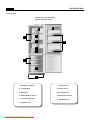
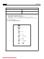
2. Interior Parts
- Features are model dependent
( Below is RF-420N model )
9
2
1
3
4
10
5
6
7
8
11
1. Refrigerator Shelves
7. Feezer Case B
2. Lamp Window
8. Freezer Case C
3. Multi Duct
9. Dairy Pocket As
4. Basket Multiple (option )
10. Refrigerator Pocket
5. Cover Vegetable Case
11. Adjustable Foot
6. Vegetable Case
2
Downloaded from Fridge-Manual.com Manuals
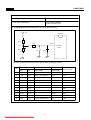
SPECIFICATIONS
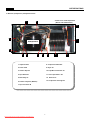
3. Machine (Compressor) Compartment View
3
- Features are model dependent
( Below is RF-420N model )
4
12
1
13
Compressor
2
5
6
7
8
9
10
1. Capacitor Run
8. Compressor Absorber
2. Power Cord
9. Dryer As
3. Suction Pipe As
10. Pipe Wire Condensor As
4. Pipe Absorber
11. Case vaporization As
5. Box Relay As
12. Drain Hose
6. Fixture Compress (Washer)
13. Compressor Cooling Fan
7. Pipe Connector B
3
Downloaded from Fridge-Manual.com Manuals
11
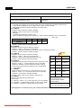
SPECIFICATIONS
4. Refrigerant Cycle
- Welding Point
Copper Welding ( Ag 5%)
6 Point
Silver Welding ( Ag 30%)
3 Point
4
Downloaded from Fridge-Manual.com Manuals
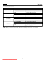
SPECIFICATIONS
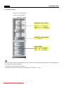
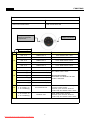
5. Temperature Diagram
* Features are model dependent
( Below model is RF-420NT )
Refrigerator Dial Mode
LOW ('1') : 3 ~ 6 degree
MID ('3') : 0 ~ 3 degree
HIGH ( '5' ) : -2 ~ 0 degree
Vegetable compartment
: 1 ~ 5 degree
Freezer Mode
HIGH : below -20 degree
MID : -18 ~ -20 degree
LOW : -16 ~ -18 degree
; The actual inner temperature varies depending on the food status, as the indicated setting temperature is a target temperature,
not actual temperature within refrigerator.
; Refrigeration function is weak in the initial time.
Please adjust temperature as above after using refrigerator for minimum 1 ~ 2 days.
5
Downloaded from Fridge-Manual.com Manuals
SPECIFICATIONS
6. Wiring Diagram
6-1. For RF-420N Models
6
Downloaded from Fridge-Manual.com Manuals
SPECIFICATIONS
6. Wiring Diagram
6-2. For RN-420N (R-600a) Models
7
Downloaded from Fridge-Manual.com Manuals
SPECIFICATIONS
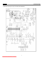
6. Main PCB Circuit Diagram ( Only for RF-420N and RN-420N Models )
8
Downloaded from Fridge-Manual.com Manuals
FUNCTIONS
1. DISPLAY
INPUT
CONTROL OBJECT
PCB Control Panel Buttons
PCB Control Panel LED
Temperature adjustment
button for refrigerator
compartment.
“Super Cool” button
Reference Page No.
10
18
11
LED DISPLAY
FUNCTION
OPERATION
LED “3” on
TEMP STEP “3”
Push “TEMP” button 1 time.
LED “4” on
TEMP STEP “4”
Push “TEMP” button 2 times.
LED “5” on
TEMP STEP “5”
Push “TEMP” button 3 times.
LED “1” on
TEMP STEP “1”
Push “TEMP” button 4 times.
LED “2” on
TEMP STEP “2”
Push “TEMP” button 5 times.
LED “S-COOL” on
TEMP S-COOL
Push “S-COOL” button 1 time.
“3” flickeringly
ERROR “R SENSOR” (R1)
“2” flickeringly
ERROR “RT SENSOR” (RT)
“1” flickeringly
ERROR “D SENSOR” (D1)
“2” & ”3” flickeringly
ERROR “DOOR S/W” (DR)
“1” & ”3” flickeringly
ERROR “CYCLE” (C1)
“1” & ”2” flickeringly
ERROR “DEFROST” (F3)
Push “S-COOL” button for continuously
and “TEMP” button 5 times.
The Priorities of Error :
R SENSOR> RT SENSOR> DR S/W>
CYCLE> DEFROST
“3” & “S-COOL” on,
“4” & ”5” flickeringly
Forced Defrost Test
Push “TEMP” button for continuously and
“S-COOL” button 5 times.
And then, push “S-COOL” button for
continuously and “TEMP” button 5 times.
“1” & “S-COOL” on
“4” & ”5” flickeringly
Pull Down Test
Push “TEMP” button 30 times.
And then, push “S-COOL” button for
continuously and “TEMP” button 5 times.
9
Downloaded from Fridge-Manual.com Manuals
FUNCTIONS
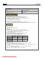
2. Temperature Control of Refrigerator Compartment
INPUT
CONTROL OBJECT
PCB Control Panel “TEMP” Buttons
PCB Control Panel LED
COMPRESSOR, FAN
R-sensor
A. “TEMP” Button
1. Temperature control of Refrigerator compartment
2. 5 step mode of successive temperature mode
3. Initial mode by power input: step “3”
4. Temperature will be set if the button doesn’t get pressed again within 5 sec.
- Whenever pressing “TEMP” button, setting is repeated in the order of
“3” → “4” → “5” → “1” → “2” (LED LAMP ON)
B. Temperature of Refrigerator Control
1. COMP and FAN will be controlled by the on/off condition of each mode.1
2. Temperature Difference of Refrigerator each step :
Temperature Step
“1”
Temp. Diff. of Each Step
“2”
2.0C
“3”
2.0C
“4”
2.0C
“5”
2.0C
3. Temperature of Refrigerator
at step “3” OFF point: is -1.4C
4. Refrigerator ON/OFF Temp.
Difference: 1.7C
C. “S-COOL” MODE
Temp
1. Press S-COOL SWITCH
and make S-COOL led lamp on.
2. COMP & FAN are on until R-sensor
reaches to “Over Refrigeration
OFF Point”, -7C
3. After the reach of -7°C , STEP “5” mode continues.
4. When “S-COOL” MODE (Quick Refrigeration Mode)
4.3 C
lasts for about 40 minutes, it returns to general
operation mode.
2.3 C
0.3 C
-1.7 C
D. Temperature of Freezer Control
-It will be only controlled by using
-3.7 C
ON
“KNOB F LOUVER” in Freezer.
2.6 C
0.6 C
-1.4 C
-3.4 C
-5.4 C
OF
Step
10
Downloaded from Fridge-Manual.com Manuals
'1'
'2'
'3'
'4'
'5'
Dial
FUNCTIONS
3. Defrost Mode
INPUT
CONTROL OBJECT
Total COMP Work Time / COMP Working Rate
Total Door Open Time / RT
Defrost Mode
Conditions of Defrost Mode
A. When total operation time of compressor becomes: 6, 8, 10, 12 hours.
- any error mode-R1, D1, F3, C1, RT/S, Door SW error- happens.
- or, running rate of COMP (per 2hrs of total operation time) is more than 80%.
- or, total door open time is over 3 minutes.
- or, ambient temperature (RT) is more than 40C.
B. Even if the above condition “A” is not satisfied,
- Defrost mode starts immediately when total operation time of COMP is 14hrs.
- or, defrost mode starts immediately as long as total time (COMP on time + COMP off time) is 60 hrs.
Defrost Mode
A. General Defrost Mode
- How to start: By conditions of defrost
- Process :
General operation“PRE-COOL” - Defrost Heater on- Pause(10 min)-General operation
; PRE-COOL: When the defrost heater works, the temp. of freezer increases.
So the COMP works for 25 min before defrost mode.
- Limited Time of Defrost Heater
; 40 minutes: Heater turns off when “D SENSOR” is OPEN or SHORT.
; 60 minutes: Heater turns off after maximum 60 minutes.
- Heater Off: When the temperature at “D SENSOR” is over 10C
PRE-COOL
Defrost
Pause
Compressor
ON
OFF
OFF
Fan
ON
OFF
OFF
Defrost
OFF
ON
OFF
B. Forced Defrost Mode
- How to start: by press “TEMP” button for continuously and “S-COOL” button 5 times.
- Process: same as General Defrost Mode except “PRE-COOL”
; Heater is supposed to be on Initial 30 seconds even though the temp. at “D SENSOR” is over 10C.
(for TEST)
- How to confirm: by press “S-COOL” button for continuously and “TEMP” button 5 times.
And then, the mode displays.
- Display : led lamps “3”& “S-COOL” on, “4” & ”5” on/off continually
11
Downloaded from Fridge-Manual.com Manuals
FUNCTIONS
3. Defrost Mode
INPUT
CONTROL OBJECT
Total COMP Work Time / COMP Working Rate
Total Door Open Time / RT
Defrost Mode
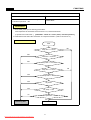
Initial Defrost
A. When initial power input or returning power failure.
if the temperature at the Defrost Sensor is below 3.5 C, Defrost Mode starts.
( It prceeds from 'PRE-COOL' ), [ PRE-COOL - Heater On - Pause (10min) - Normal Operation ]
B. Initial defrost mode starts after 'Prevention of Compressor Restart'. ( Refer to function No. 5 )
Flow Chart of Defrost Start
Start
Comp time >= 2 hours
No
Yes
Yes
Total time >= 60 hours
No
Yes
Comp time >= 14 hours
No
Comp time >= 6 hours
Yes
Yes
Comp Rate >= 80%
No
Yes
Any Error?
No
Yes
RT Temp >= 40C
No
Ye
Total door open time >= 3min?
No
Defrosting Start
END
12
Downloaded from Fridge-Manual.com Manuals
No
FUNCTIONS
4. Function of Low Ambient Temperature (RT)
INPUT
CONTROL OBJECT
RT
R-HTR
COMP
A. Condition of LOW RT
- LOW RT Period : RT sensor below 19C
- When the temperature of RT sensor is over 20C, the system comes to be “General Operation Mode”.
- When the temp. of RT sensor is between 19°C to 20C, the system keeps the previous mode.
B. Control
- When Comp. is on, R-HTR is off.
- When it passes 6 min after COMP is off, R- HTR is on.
- COMP can’t be on within 30 min after COMP is off.
; COMP doesn’t work at the steps “Heater On” and “Pause” of “Defrost Mode”.
If COMP comes to be off for “Low Room Temp” in the steps, it seems to take over 30 minutes.
- Change of “Prevention Time of COMP Restart” :
If satisfy the following conditions simultaneously, the time changes 6 minutes.
; Accumulated running time of COMP passes 20 seconds after COMP is off.
; R-Sensor is more than ‘ON’ Point TEMP.
- When it is not the mode of LOW ROOM TEMP
or RT-Sensor is on ERROR (open or short), R-Sensor HTR is off.
- Function of R-Heater Inspection:
After initial power is on, R-HTR is on/off 5times for 10 seconds.
- When Defrost Heater is on, R-Sensor Heater is on
5. Prevention of Compressor Restart
INPUT
CONTROL OBJECT
COMP
COMP. doesn’t work after COMP turns off even though R-sensor is on condition. (This is to protect comp.)
A. General operation (Temp. at the RT sensor is over 20C): The COMP can’t be on within 6 min.
B. Operation of LOW RT (Temp. at the RT sensor is below 19C):
The COMP can’t be on within 30 min.
(But the COMP can be on after 6min when the doors open more than 20 seconds.)
6. Buzzer Sound
INPUT
CONTROL OBJECT
Control Buttons / Door Switch
Initial Power Input
Buzzer
A. Whenever “PCB Control Panel” button’s pushed, the buzzer rings.
B. After 2 minutes power’s on, the buzzer rings 3 times.
C. Time of Buzzer: Forced Defrost Mode (3 times), Short Circuit Test (1 time)
D. When door opens, the buzzer rings every 1 minute for 5 minutes.
13
Downloaded from Fridge-Manual.com Manuals
FUNCTIONS
7. Time Reduction
INPUT
CONTROL OBJECT
”FAST KEY”
Buzzer
A. HOW TO REDUCE
- 1 min : Click FAST KEY one time on MAIN PCB.
- 30 min : If you press FAST KEY continuously, you can reduce 30 minutes on each 2.5 seconds with
buzzer.
B. Practice Use : Can be applied to reduce needless time on test.
EX) function of stop for 6 min
8. Demonstration Function
INPUT
CONTROL OBJECT
“TEMP” +”S-COOL” Buttons
Display Panel
A. START : by pressing “TEMP” and “S-COOL” buttons for 5 seconds.
B. CONTROL :
- All electronic compartments are off except “Display Panel”.
- When “DEMO” mode works, led lamps will be on as next steps.
[ “1” → “2” → “3” → “4” → “5” → “1”]
C. CANCEL :
Push again “TEMP” and “S-COOL” buttons for 5 seconds at “DEMO”, or turn off power and restart.
14
Downloaded from Fridge-Manual.com Manuals
FUNCTIONS
9. Control of R-sensor OFF Point
INPUT
CONTROL OBJECT
”J1” , “J2” On Main PCB
Control Resistance of R sensor OFF Point
A. LOW COOLING OPTION ( Weak Cooling )
- When the refrigeration of refrigerator is poor or weak though Fan and COMP are working continuously,
the following actions are recommended for service.
- Resistance (R47) : Default resistance (31.4Kohms)
- Resistance (R45) : Cut the “J1” off to reduce basic resistance by 1.5°C. (2Kohms up)
- Resistance (R42) : Cut the “J2” off additionally to reduce basic resistance by 1.5°C. (total 4Kohms
up)
R47 = R-SENSOR OFF point
R47 + R45 = R-SENSOR OFF point - 1.5C
R47 + R45 + R42 = R-SENSOR OFF point - 3C
R-SENSOR
R47(31.4K)
R45(2K)
J1
R42(2K)
J2
15
Downloaded from Fridge-Manual.com Manuals
FUNCTIONS
9. Control of R-sensor OFF Point
INPUT
CONTROL OBJECT
Input voltage of MICOM
R-sensor ON/OFF Point
”J3” & “R30” On Main PCB
B. Prevention OPTION of EXCESSIVE OR LOW COOLING.
5V
MICOM
R31
R32
26PIN
Va
OPTION 3
(P63)
R30
J3
CC3
; The input voltage of MICOM and R-Sensor ON/OFF point by changing J3 & R30.
TEMP. STEP “3”
APPLICATION
MICOM
ON
OFF
(MAIN PCB)
INPUT VOL.
1
0.3C
-1.4C
-
0V
STANDARD
2
-1.4C
-3.1C
J3(CUT), R30 (680ohm)
0.3V
-1.7C
3
-1.1C
-2.8C
J3(CUT), R30 (2kohm)
0.8V
-1.4C
4
-0.8C
-2.5C
J3(CUT), R30 (2.8kohm)
1.1V
-1.1C
5
-0.4C
-2.1C
J3(CUT), R30 (3.92kohm)
1.4V
-0.7C
6
-0.1C
-1.8C
J3(CUT), R30 (4.87kohm)
1.6V
-0.4C
7
0.7C
-1.0C
J3(CUT), R30 (6.65kohm)
2.0V
+0.4C
8
1.0C
-0.7C
J3(CUT), R30 (10kohm)
2.5V
+0.7C
9
1.4C
-0.3C
J3(CUT), R30 (19.6kohm)
3.3V
+1.1C
10
1.7C
0C
J3(CUT), R30 (40.2kohm)
4V
+1.4C
11
2.0C
0.3C
J3(CUT), R30(NO USE)
5V
+1.7C
NO
16
Downloaded from Fridge-Manual.com Manuals
Compared to
“STANDARD”
FUNCTIONS
9. Control of R-sensor OFF Point
INPUT
CONTROL OBJECT
Input voltage of MICOM
R-sensor ON/OFF Point
”J4” & “R23” On Main PCB
C. Changing Difference between R-sensor “On” point and “Off” point.
5V
MICOM
R25
R28
27PIN
Va
OPTION 2
(P64)
R23
J4
CC6
; The input voltage of MICOM and R-Sensor ON/OFF DIFF. by changing J4 & R23.
TEMP. STEP “3”
APPLICATION
MICOM
ON
OFF
(MAIN PCB)
INPUT VOL.
1
0.3C
-1.4C
-
0V
1.7C
2
-1.0C
-1.4C
J4(CUT), R23 (680ohm)
0.3V
0.4C
3
-0.7C
-1.4C
J4(CUT), R23 (2kohm)
0.8V
0..7C
4
-0.3C
-1.4C
J4(CUT), R23 (2.8kohm)
1.1V
1.1C
5
0C
-1.C
J4(CUT), R23 (3.92kohm)
1.4V
1.4C
6
0.7C
-1.4C
J4(CUT), R23 (4.87kohm)
1.6V
2.1C
7
1.1C
-1.4C
J4(CUT), R23 (6.65kohm)
2.0V
2.5C
8
1.4C
-1.4C
J4(CUT), R23 (10kohm)
2.5V
2.8C
9
1.8C
-1.4C
J4(CUT), R23 (19.6kohm)
3.3V
3.2C
10
2.1C
-1.4C
J4(CUT), R23 (40.2kohm)
4V
3.5C
11
2.5C
-1.4C
J4(CUT), R23(NO USE)
5V
3.9C
NO
17
Downloaded from Fridge-Manual.com Manuals
DIFFERENCE OF
ON/OFF POINT
FUNCTIONS
10. Error Display
INPUT
CONTROL OBJECT
PCB Control Panel Buttons / Door
LED Lamp
- ERROR DISPLAY
- To confirm error happens or not, push S-COOL” button for continuously and “TEMP” button 5 times.
- To stop the Error Display Set, push “TEMP” button 1 times, or wait 4 minutes.
- After operations back to normal, the displays come to be reset.
A. R1 ERROR
(It happens when R-Sensor is OPEN or SHORT)
- DISPLAY : STEP “3” LED is on & off continually.
- CONTROL :
; Controlled by the following condition of RT
; When “RT ERROR” happens at the same time, “COMP. ON/OFF Operating Time” is 16min/24min.
(Unit : min)
RT sensor TEMP
~13C
~19C
~29C
29C ~
COMP. Operating TIME
(ON/OFF)
6/34
10/30
16/24
20/20
- CANCEL : when R-Sensor is working normally.
B. RT ERROR
(It happens when RT-Sensor is OPEN or SHORT)
- DISPLAY : STEP “2” LED is on & off continually.
- CONTROL : Delete the conditions of “RT-sensor Control” and operate normally.
- CANCEL : when RT-Sensor is working normally.
flicker
C. D1 ERROR
(It happens when D-Sensor is OPEN or SHORT)
- DISPLAY : STEP “1” LED is on & off continually.
CODE
LED
ERROR
- CONTROL : Return to next limit defrost time (40 min)
- CANCEL : when D-Sensor is working normally.
R1
“3”
R sensor
D. DR ERROR
(It happens when the system senses door opens more than 1 hour.)
RT
“2”
RT sensor
- DISPLAY : STEP “2”, “3” LED Lamps are on & off continually.
- CONTROL : Deletion of function related door switch sensing
D1
“1”
D sensor
- If door switch (open & close) is sensed, the error is terminated
automatically
DR
“2”, “3” DR Switch
E. C1 ERROR
(When D-Sensor is more than -5C, Comp operates over 3 hrs)
C1
“1”, “3” Cycle
- DISPLAY : STEP “1” & “3” LED Lamps are on & off continually.
- CONTROL : The system is normally operating
F3
“1”, “2” Defrost
- CANCEL : When Comp is off, D-Sensor is less than -5C.
F. F3 ERROR
- To Confirm Errors:
Return to next step after max defrost time.
Push “S-COOL” for
( 60 minutes )
continuously and “TEMP”
6.1- DISPLAY : STEP “1” & “2” LED Lamps are on & off continually.
button 5 times.
6.2- CONTROL : At Defrost Mode, Deletion of “PRE-COOL” Mode.
- The Priorities of Error :
6.3- CANCEL : Completion of defrost returned by D-Sensor.
R1→RT→D1→DR→C1→F3
- If the appliance is normal (no error), just '4' and '5' LED flicker in Error Mode.
18
Downloaded from Fridge-Manual.com Manuals
FUNCTIONS
11. Function Key Summary Table
MODE
Forced Defrost Mode
Pull Down Mode
Error Display
Action
Button / Remark
How to enter the Mode
Temp + S-Cool button 5 times
How to terminate
After Mode ends ( about 1 hour )
Display
'3', 'S-Cool' LED ON (In Error Mode)
How to enter the Mode
Temp button 30 times
How to terminate
After Mode ends ( about 30 hour )
Display
'1', 'S-Cool' LED ON (In Error Mode)
How to enter the Mode
S-Cool + Temp button 5 times
How to terminate
emp button 1 time or after 4 minutes
Display
'4', '5' LED flicker (When no error happens)
How to enter the Mode
Temp + S-Cool button for 5 seconds
How to terminate
Temp + S-Cool button for 5 seconds
Demo Mode
LED Lamps will be on as next steps.
Display
( '1' - '2' - '3' - '4' - '5' - '1' )
In Error Mode, you can find the current mode ( What mode is operationg ) and what kinds of Error happen.
19
Downloaded from Fridge-Manual.com Manuals
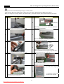
DISASSEMBLY
1. Front PCB
Procedure
No
No
1
Procedure
3
Inuput a cutter sleeve between Window FCP and Panel
F control. ( Be careful not to scratch the surface. )
Unscrew Panel F Control.
2
4
Lift up the Window FCP.
( Input cutterr deeply to lift up easily.)
Pull up the Panel and disconnect the wire connector.
2. Door Switch
2-1. RF-420N.. Models
Procedure
No
No
1
Procedure
2
Inuput a thin driver in the right part as above picture.
Move switch to left side.
And lift up to remove.
Disconnect the wire housing.
20
Downloaded from Fridge-Manual.com Manuals
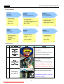
DISASSEMBLY
2-2. RN-420N.. Models
Procedure
No
No
1
Procedure
3
Remove top cover hinge screw with (+) driver.
Remove the Door Switch from the cover hinge.
2
4
Separate the Cover hinge by using driver.
Disconnect door switch connector.
Be careful not to scratch the cabniet surface.
3. Multi-Duct As ( In Freshfood Compartment )
Procedure
No
No
Procedure
1
Remove screw cap with flat driver
3
2
Unscrew 2 points
Disconnect the Lamp & Sensor wire housing.
21
Downloaded from Fridge-Manual.com Manuals
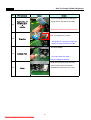
DISASSEMBLY
4. Freezer Louver As
No
Procedure
Procedure
No
1
4
Unscrew the fixing screw to remove the Louver F As
Remove 3 screws in order to disassemble Louver F As.
2
5
Remove the Louver F As pulling the top side.
When disassembling check the Knob position.
3
6
L M H
Disconnect Fan motor wire housing.
Default position is 'M'
22
Downloaded from Fridge-Manual.com Manuals
How to change Door opening Dirction (Reversable)
Below process is for RN-420N (Refrigerant type : R-600a) models.
Some parts are differ to RF-420N models. ( Hinge Cover, Door Switch, Wire Harness and Button Door Switch. )
When you change door opening direction ( RF-420N models ), please refer page 20 (Door switch Disassemlby) and below.
No
Procedure
Procedure
No
Button
1
Hidden
Wire
6
Cover Bushing
After hiding door wire harness, remove the button Door
Remove top cover hinge screw with (+) driver.
Switch and Cover Bushing.
2
7
After unscrewing the Cover Hinge Harness *T *L,
Separate the Cover hinge by using driver.
disclose the door wire harness.
Stopper
3
8
Reassemble the cover and button door switch.
And also assemble the door stopper to opposite side.
Remove the Door Switch from the cover hinge.
(Which is located the Door under Cap. )
4
9
Freezer Door
Remove the Middle Hinge.
Disconnect all wire connector and hinge.
Assemble Cover Bushing & Stopper to the opposite.
a. Change the location
(screw & division hinge cap)
5
10
Refrigerator Door Cap
b. Change the unnder hinge
Unscrew the Cover Hinge Harness *T *R
location to the opposite.
and hide the door wire harness.
23
Downloaded from Fridge-Manual.com Manuals
How to change Door opening Dirction (Reversable)
No
Procedure
No
11
Procedure
14
Screw the middle hinge to fix the Freezer Door.
Connect the wire harness to door swtich.
( Washer should be up. )
( Be careful the dircetion. )
12
15
Also assemble wire cover on the top plate. ( On the right
13
Change the plate position and separate door switch.
24
Downloaded from Fridge-Manual.com Manuals
Assemble Door and hing cover.
How To Charge R-600a Refrigerant
1. Safety Warning ( R-600a Refrigerant Models Only, RN-420N.. )
This appliance contains a certain amount of isobutane refrigerant (R600a) a natural gas with high
environmental compatibility that is, however, also combustible.
When transporting and installing the appliance, care should be taken to ensure that no parts of the
refrigerating circuit are damaged.
Refrigerant squirting out of the pipes could ignite or cause an eye injury. If a leak is detected, avoid
any naked flames or potential sources of ignition and air the room in which appliance is standing for
several minutes.
- In order to avoid the creation of a flammable gas-air mixture if a leak in the refrigerating circuit occurs, the size of the room
in which the appiance may be sited depends on the amount of refrigerant used. The room must be 1m3 in size for every 8g
of R600a refrigerant inside the appliance. The amount of refrigerant is shown on the identification plate inside the appliance.
- Never start up an appliance showing any sings of damage. If in doubt, consult your dealer.
2. Tools
25
Downloaded from Fridge-Manual.com Manuals
How To Charge R-600a Refrigerant
3. Process Summary
1st Step.
R-600a ref.
discharging
2nd Step.
Removing
the remaning refrigerant
- Connect the discharging hose to
the outdoors.
- Time : 7 min.
4th Step.
Welding
coupling pipe
3th Step.
Exchanging comp.
& dryer / pipe welding
- For removing of
remaning refrigerant.,
connect the discharging hose to
the vacuum pump
-Time : 10min
6th Step.
Charge R-600a
5th Step.
Vacuum
Coupling cap and
gas charging cap
should be
seperated before
welding.
- Exchange Comp. and Dryer
- Welding the Pipe
- Copper-Copper : 5% rod
- Copper-Steel : 30% rod
- Check the vacuum
with (mani-polder)
gauge
- Charging the ref.
on POWER ON
- Time : 60~80min
- Time : 10min
4. In Detail Precess
NO.
SVC process
1
Connecting
the
pinch-plier
&
discharging
hose
Image
Details
1. Connect the discharging hose to
the pinch-plier
OUT DOOR
2. The outlet of discharging hose should
be placed to the outdoor(window)
1. Fix the pinch-plier to the compressor
2
charging pipe.
Fix ing
the pinch-plier
&
charging pipe
2. Pinch-plier should not be moving freely.
※ If that is moving freely, it would cause
fire/explosion as leakage gas in the room.
1. Discharge the R-600a ref. to outdoor.
[Befor connecting the vacuum pump]
3
Discharging
the R-600a ref.
※ It should have enough time more than
7 minutes to discharge.
26
Downloaded from Fridge-Manual.com Manuals
How To Charge R-600a Refrigerant
NO.
S VC process
Image
Details
1. And then, connect the vacuum pump
to the outlet of discharging hose
4
Remov ing the
remaining ref.
※Vacum pump should be placed at
the outdoor where is able to clear air easily.
※ It should have enough time
more than 10 minutes to discharge.
1. Disassembe the each pipe (Del-pipe,
Suc-pipe, Capi-pipe, Dryer & Hot-pipe)
5
Remov ing the
pinch-plier & pipe
※ Caution ; A part is easily damaged
by flame so that disassemly should
be done carefully.
1. Change the comp. & dryer.
6
Ex changing comp
& dry er
※ You should check the comp. spec.
and assemble correctly.
1. Weld the each pipe.
7
8
※ O Copper-Copper welding - 5% rod
W elding
30%rod
rod
△ Copper-Steel welding - 35%
Disassembly
of charging v alv e
(Coupling pipe)
Valve Ass'y
1. Decap the couplig pipe cap and
Valve Ass'y
disassemble the vlave ass'y.
※ If you don't disassemble, the coupling
rubber would be melted.
27
Downloaded from Fridge-Manual.com Manuals
How To Charge R-600a Refrigerant
NO.
SVC process
Image
Details
1. Weld after inserting the coupling pipe
to the compressor.
9
Coupling pipe
welding
※ Use the wet cloth for preventing the
other part of machinery-room from damage.
1. Reassemble the valve ass'y with
coupling pipe to clockwise.
2. Connect the blue hose of the guage
to the coupling pipe and the yellow hose
10
Valv e reass' y
&
guage connecting
to the vacuum pump.
3. Open the blue guage lever
and start the vacuum pump
1. Be vacuumed the cycle with pump.
11
Vacuum
※ Time : 60~80min
=> If the vacuum time is less than 60min,
ref. COP & air coolong would be weak.
1. Check the guage : -76㎝Hg
12
Check
※ If the cycle is not vacuumed,
it would be leak.
1. Check the amounts of R-600a can
with scale and discharge the surplus ref.
13
※ Discharging is surely done at the outdoor
where is able to clear air.
Adjusting
the amounts of
refrigerants
(R-600a can)
※ Tip of adjusting.
- Can total weight :160g(Can 75g+Ref. 85g)
- Adapter : 145g
=> Total : 305g
- The amounts of charging : 79g
=> Discharging : 6g => Total : 299g
28
Downloaded from Fridge-Manual.com Manuals
How To Charge R-600a Refrigerant
NO.
S VC process
Image
Details
1. Conect can adapter to the coupling pipe.
14
2. Charge the ref. with open lever slowly.
Connecting of
coupling pipe
&
adapta
※ Refrigerant should never leak in the room.
1. On the power of refrigerator and then
start to charge the ref. (10min)
15
Charging
※ Charge the ref. until going out the water
vapour condensing on the can outlet.
1. Check the leakage.
16
Leakage Test
※ You must rework from Step.1
when the leakage is detected.
1. Clean and clear around the machinery
room when the service is finished.
17
Finish
2. Assemble the machinery room cover.
29
Downloaded from Fridge-Manual.com Manuals
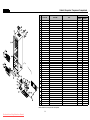
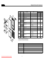
Cabinet
Cabinet / Evaporator / Compressor Compartment
NO
PART-CODE
1
2
2
3
4
5
6
7
8
9
10
10-1
10-2
10-3
11
11-1
11-2
12
13
14
15
3001416620
30143G1060
30143G1070
3001412220
3018125601
3001427720
3012929000
3001411920
3018120200
3010937710
3017065200
3012764100
3017202800
3012822000
3017068200
3012769400
3012823000
3012928900
3012105101
3001415620
3012929100
COVER M/PCB BOX AS
PCB MAIN AS
PCB MAIN AS
COVER CAB HRNS
SWITCH H/BAR DR AS
COVER *T HI AS
HINGE *T AS
COVER *T HI
SWITCH DR AS
CAP DV HI HOLE *M
EVA AS
HARNESS D SENS
FUSE TEMP AS
HEATER D AS
EVA AS
HARNESS D SENS
HEATER SHEATH AS
HINGE *M AS
FOOT ADJ AS
COVER CAB BRKT AS
HINGE *U AS
20
21
22
23
24
25
26
3014469600
3010102100
3015918110
3012532000
3011122800
3011802700
3016808900
3956158K50
3956141250
3016002500
3018131810
3018132900
3811400503
3811402100
3010101600
3010101480
3010349301
3016401160
3016401920
3011349300
3001414000
PIPE WICON AS
ABSORBER C MOTR
MOTOR C FAN
GUIDE DRN
CASE VAPORI AS
FAN AS
DRYER AS
COMPRESSOR
COMPRESSOR
SPECIAL WASHER
SWITCH P RELAY AS
SWITCH P RELAY AS
COVER RELAY
COVER RELAY
ABSORBER COMP
ABSORBER COMP AS
BASE COMP AS
CAPACITOR RUN
CAPACITOR RUN
CORD POWER AS
COVER MACH RM AS
27
28
29
30
31
32
33
34
35
PART NAME
Please check the color, some parts code color dependent.
30
Downloaded from Fridge-Manual.com Manuals
SPEC.
Q'ty
COLOR DEPENDENT
V-LAZER (RFP-340)
V-LAZER (RFP-340 R600A)
COLOR DEPENDENT
COLOR DEPENDENT
COLOR DEPENDENT
RFP-340
COLOR DEPENDENT
83430-109-19(NO.411260025)
COLOR DEPENDENT
RFP-340
RFP-340(NBC-K43-24)
SW-105T(77)
AC230V, 180W
RFP-341
PBN-43
RFP-341
RFP-340
PP(BLACK)
COLOR DEPENDENT
RFP-340
RF-430N
1
1
x
1
x
x
1
1
1
1
1
1
1
1
x
x
x
1
2
1
1
RN-430N
1
x
1
1
1
1
x
x
x
1
x
x
x
x
1
1
1
1
2
1
1
RFP-340
NR FRB-5350NT
S6112CEC01
GA, T0.4 AL
.
FAN(OD110)+CLAMP
RFM-340 OD19.05 V-LAZER
YX58LHP5 220V-50HZ
MD4A1Q-L1U 220/240V-50HZ
SK-5 T0.8
RFP-341
RFP-341 189PHB,S330
PP(SW5101SW) 40*54*45*T2.0
DS3-3NORYL S/S
NBR
FRU-541D
RFP-340(BASE COMP/T1.0)
350VAC 4UF(WIRE)
400VAC 5UF(WIRE)
16A , 250V
RFP-340
1
1
1
1
1
1
1
1
x
3
1
x
1
x
4
x
1
1
x
1
1
1
1
1
1
1
1
1
x
1
3
x
1
x
1
x
4
1
x
1
1
1
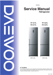
Refrigerator & Freezer Compartment
Cabinet
PART NAME
SPEC.
PART-CODE
40
3017847100
SHELF R INSERT AS
.
2
2
41
3010669900
BRACKET MULTI
GPPS
1
1
42
3017847100
SHELF R INSERT AS
.
1
1
43
3001413300
COVER V/CASE AS
COVER+KNOB
1
1
44
3011197500
CASE VEGETB
GPPS
1
1
45
3015513100
WINDOW R
MIPS
1
1
46
3013603000
LAMP
240V,25W(BLUE)
1
1
47
3001413500
COVER MULTI DUCT AS
RFP-340
1
1
47-1
3017903900
SOCKET LAMP AS
AC250V
1
1
47-2
3012764600
HARNESS R SENS
RFP-340(NBC-K43-D21)
1
1
48
4010G56012
CASE ICING
PP(J-360)
1
1
49
3012535500
GUIDE F CASE
PP
1
1
50
3011197900
CASE F B AS
CASE+WINDOW
1
1
51
3011197900
CASE F B AS
CASE+WINDOW
1
1
52
3011198000
CASE F C AS
CASE+WINDOW
1
1
RF-430N
RN-430N
53
3018927900
LOUVER F AS
RFP-341
1
1
53-1
3015918210
MOTOR F FAN
S6112CDF03
1
1
53-2
3011835900
FAN
OD100,SHAFT OD3.17
1
1
53-3
3013413500
KNOB F CONTL
PP
1
1
Some parts can be changed for improving without notice.
Date
Note
31
Downloaded from Fridge-Manual.com Manuals
Q'ty
NO
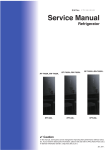
Refrigerator & Freezer Door Compartment
Cabinet
NO
PART-CODE
PART NAME
60
3019056100
POCKET DAIRY AS
61
3011190800
62
SPEC.
RN-430N
RFP-341
1
1
CASE EGG TRAY
GPPS
1
1
3019055900
POCKET BOTL
GPPS
2
2
63
3012532100
GUIDE BOTL POKT
PP
1
1
64
3019055800
POCKET JUMBO
GPPS
1
1
1
1
1
1
1
1
RFP-341(WHITE)
3000077800
65
3000077820
ASSY R DR
65-1
3012321200
GASKET R DR AS
3011783320
RFP-340
RFM-341(TWHITE)
3011783300
65-2
RFP-341(SILVER)
RFP-341(T/SILVER)
3000077840
DOOR R PRE AS
RFM-341(SILVER)
RFM-341(T/SILVER)
3011783340
66
3016307700
BUTTON DR SW
ABS
x
1
67
3014240140
PANEL F PCB AS
RFP-341(T/SILVER)
1
1
67-1
30143G1160
PCB FRONT AS
V-LAZER FRONT AS (RFP-340)
1
1
1
1
1
1
1
1
RFP-341(TWHITE)
3000077500
68
3000077510
ASSY F DR
RFP-341(T/SILVER)
3011783220
68-1
3011783220
DOOR F PRE AS
3012321100
RFP-341(T/SILVER)
RFP-341(T/SILVER)
3011783220
68-2
RFP-341(SILVER)
RFP-341(T/SILVER)
3000077520
GASKET F DR AS
RFP-340
Some parts can be changed for improving without notice.
Please check the color, some parts code color dependent.
Date
Downloaded from Fridge-Manual.com Manuals
Q'ty
RF-430N
Note
32