1
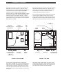
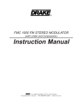
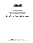
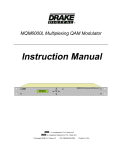
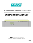
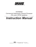
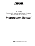
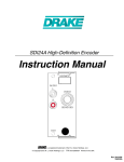
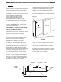
VHF CONVERTER INSTALLATION INSTRUCTIONS for R8 Series Receivers
1
CAUTION: Refer installation to qualified service technician to prevent personal injury or damage to the equipment.
Locate the Retaining Bracket and position to the edge
of the VHF Converter assembly as shown. On the
R8A/R8B be sure to re-insert the (front panel) board
shield into the slot on the retaining bracket when
installing the VHF Converter. Use the supplied #4-40 x
1/4 Pan Head Philips screw to secure the bracket to the
receiver chassis (Figure 2).
Prior to starting installation of your new VHF converter,
carefully unpack the converter PC board assembly and
its associated cables and mounting hardware. You will
need to use a Philips screwdriver during installation.
NOTE: A magnetized screwdriver facilitates the removal
and installation of screws in the procedure that follows.
Identify the following items:
(1) #1001590 VHF Converter Assembly
(1) #3711160 Coaxial Cable, 8" Length
(1) #3711168 Coaxial Cable, 26" Length
(1) #2707293 6-Conductor Cable,17" Length
*(1) #4350171 Retaining Bracket
*(1) #3320244 Screw 4-40 x 1/4" Pan Head Philips
BRACKET
*NOTE: Retaining Bracket and Screw are already
installed in an R8A/R8B receiver. Install the VHF
Converter assembly as follows:
SHIELD
DISCONNECT THE RECEIVER FROM
THE AC POWER SOURCE!
1) Remove the top cover from the receiver by removing
(5) #6-32 x 1/4" BLACK Pan Head Philips screws.
Retain the cover and screws for reassembly.
2) Remove the bottom cover from the receiver by
removing (6) 4-40 x 1/4" Pan Head Philips screws.
Retain the cover and screws for reassembly.
SCREW 4-40 X 1/4"
PAN HEAD Philips
FIGURE 2
3) Reposition any cables at the rear panel, as
necessary, to allow the converter assembly to fit at the
rear panel wall. Dress these cables away from the
SO-239 antenna input connectors and gently pull any
excess cable toward the bottom compartment of the
receiver chassis. On the R8A/R8B, the VHF Converter
Retaining Bracket is already installed in the radio,
holding the right side of a front panel area board shield.
Remove this bracket by removing the #4-40 x 1/4"
screw at the base of the bracket. Retain the bracket
and screw for later reassembly. Position the VHF
converter assembly into the chassis as illustrated
(Figure 1). The board mounted components should
face toward the outside edge of the receiver, with the
larger of the two component side shields toward the
rear panel of the receiver. Align the two tabs into the
slots located on the rear panel of the receiver.
4) Identify the 6-conductor cable (17" length) and plug it
onto the VHF converter assembly connector header
(Figure 1). Be careful to observe that the RED
conductor end of the cable connector is oriented as
shown in Figure 1.
5) Route the free end of the 6-conductor VHF converter
cable vertically down behind the front panel (near the
Volume Control) to the board assembly exposed by
removal of bottom cover. See Figure 1.
BRACKET
FRONT
PANEL
FIGURE 1, RECEIVER SIDE VIEW
SHIELD
6-CONDUCTOR CABLE
RED WIRE
TABS
REAR
PANEL
SHIELD
VHF CONVERTER ASSEMBLY
2
Installation, continued
6) Position the receiver so it rests on its left-hand side
(facing the front of the receiver). Locate the unconnected end of the 6-conductor cable and plug it onto the
synthesizer board connector header with the RED
conductor end of the cable connector oriented as
shown in Figure 3. Position the cable assembly, routing
it as shown, to keep it clear of the microprocessor and
related circuits area of the board assembly. Reduce
any excess slack of the cable near the VHF converter to
provid proper routing on its approach to the synthesizer
board connector header.
8) Position the receiver so it rests on its bottom chassis
with front panel facing towards you. Plug the unconnected end of the 26" 'REF' coaxial cable #3711168,
into the "REF IN" connector located on the VHF
converter assembly as shown in Figure 4.
9) Locate the factory installed coaxial cable connected
to the rear panel "CONV" antenna input connector.
Disconnect the terminal end of this coax from the Front
End Board connector. Plug the coax cable into the 'RF
IN' terminal of the VHF Converter as shown in Figure 4.
VHF
CONVERTER
#2707293
THIS END TO VHF
CONVERTER
ROUTE
6-CONDUCTOR
CABLE
REF
OUT
"CONV" ANT INPUT
"ANT 1"
INPUT
REAR
PANEL
SHIELD
RF
"IF IN"
RED WIRE
"RF IN"
SYNTHESIZER
BOARD
#3711160
"IF OUT"
SHIELDS
"REF IN"
THIS END TO VHF
CONVERTER
"REF IN"
CONNECTOR
#3711168
26" CABLE
FRONT
PANEL
#3711168
BRACKET
6-CONDUCTOR
CABLE ROUTE
FIGURE 3, BOTTOM VIEW
FIGURE 4, TOP VIEW
7) Connect the supplied 26" "REF" coaxial cable
#3711168 to the 'REF OUT' connector located near the
right rear corner of the synthesizer board. Position the
cable as shown in Figure 3, routing the free end of the
coax cable along the front panel (near volume control)
and up to the VHF Converter assembly end nearest the
front panel.
10) Identify the 8" Coaxial Cable, #3711160. Plug in
one end of the cable to the 'IF IN' terminal on the Front
End board assembly and plug the other end into the 'IF
OUT' terminal of the VHF Converter assembly.
Installation - Unit System Check
The VHF Converter electrical installation is complete at
this point. Prior to applying AC power to the receiver for
testing, proceed as follows:
11) Position the receiver with the bottom of the unit
facing up, front panel toward you. Place the bottom
cover on the unit oriented with the lever feet or metal
bail toward the front panel of the receiver. Secure the
bottom cover using (6) #4-40 x 1/4 " Pan Head Philips
screws that were removed in step #2.
3
The unit should automatically switch to the converter
antenna input if any frequency in the range of either 35
- 55 MHz or 108 - 174 MHz is selected. (If the above
action does not occur, check the 6-conductor cable
assembly of the VHF converter). Once proper
operation is noted, tune in a known active signal in
either the range of 35 - 55 MHz or 108 - 174 MHz.
Select the proper mode, bandwidth and other
parameters as appropriate.
NOTE: You may wish to secure the bottom cover with
(2) screws until after unit system check, but note that
AC power is active at all times in the receiver
whenever it is connected to a source of AC power.
HINT: In many areas of the U.S., the NOAA weather
stations are active on one of the following frequencies:
162.400 MHz, 162.475 MHz or 162.550 MHz. One of
those or a similar type station could be tuned in as a
convenient operational check.
12) Position the receiver with the top of the unit facing
up, front panel towards you. Install the top cover using
the (5) #6-32 x 1/4" Pan Head Philips BLACK screws
retained in step #1.
Once correct operation is verified, disconnect the
receiver from the AC Power Source. Secure the top
and bottom covers with remaining screws if this has not
already been completed in steps #11 and #12.
UNIT SYSTEM CHECK
13) Connect the receiver to a source of AC power.
Press the 'POWER' button to place the receiver in the
'ON' mode.
The receiver with VHF Converter is now ready for
operation.
VHF OPERATION
Operation of the receiver in the VHF Bands of
35-55 MHz and 108-174 MHz is accomplished by
entering the desired frequency as described in the
"DIRECT FREQUENCY ENTRY" section of the
Receiver Owner's Manual. Additionally, the receiver will
automatically tune to the 35-55 MHz band followed by
the 108-174 MHz band as the main tuning dial is tuned
above 30 MHz. All reception modes are
supported in the two VHF bands.
4
Specifications
SPECIFICATIONS:
Frequency Range:
Antenna Impedance:
Sensitivity - SSB, CW
(+10dB S+N/N):
(Apply to the operation of the VHF Converter
assembly installed in R8 series receivers).
35-55 MHz, 108-174 MHz.
50 Ohms.
Less than 0.25 µV (2.3 KHz Bandwidth).
Sensitivity - AM
(+10 dB S+N/N)
(1 KHz, 30% mod):
Less than 1.0 µV.
Sensitivity - FM
(12 dB SINAD):
Less than 0.5 µV.
Frequency Stability:
Power Requirements:
FCC Approval:
Weight:
Size:
Better than ±10 ppm, -100 to +500 C (determined by
the receiver's master reference oscillator).
+10 VDC @ 150 mA.
Part 15 Certification.
6.7 Oz. (0.2 Kg).
Length 9-5/8" (24.4 cm),
Width 2-1/2" (6.4 cm),
Height 1-1/8" (2.9 cm).
®
R.L. Drake Company
230 Industrial Drive
Franklin, Ohio 45005 U.S.A.
CUSTOMER SERVICE AND PARTS TELEPHONE: +1 (937) 746-6990
TELEFAX: +1 (937) 743-4576
WORLD WIDE WEB SITE: http://www.rldrake.com
® is a registered trademark of the R.L. Drake Company
© Copyright 2001 R.L. Drake Company
P/N: 3851590J-8-2001
Printed in U.S.A.