1
HiPath
optiPoint IP Phones
Deployment Tool V1.2.33
Administrator Manual
Contents
Contents
Introduction. . . . . . . . . . . . . . . . . . . . . . . . . . . . . . . . . . .5
Supported Phones. . . . . . . . . . . . . . . . . . . . . . . . . . . . . . . . . . . . . . . . . .
Requirements . . . . . . . . . . . . . . . . . . . . . . . . . . . . . . . . . . . . . . . . . . . . .
Operating System . . . . . . . . . . . . . . . . . . . . . . . . . . . . . . . . . . . . . . .
Screen Resolution . . . . . . . . . . . . . . . . . . . . . . . . . . . . . . . . . . . . . . .
FTP Service . . . . . . . . . . . . . . . . . . . . . . . . . . . . . . . . . . . . . . . . . . . .
5
6
6
6
6
Installing and Running the Program. . . . . . . . . . . . . .7
Installing the Program . . . . . . . . . . . . . . . . . . . . . . . . . . . . . . . . . . . . . . . 7
Starting the Program . . . . . . . . . . . . . . . . . . . . . . . . . . . . . . . . . . . . . . . . 7
Listing Connected IP Phones . . . . . . . . . . . . . . . . . . . .8
Icons and Buttons . . . . . . . . . . . . . . . . . . . . . . . . . . . . . . . . . . . . . . . . . . 9
Creating a Device List . . . . . . . . . . . . . . . . . . . . . . . . . . . . . . . . . . . . . . 10
Specifying the Number of Scans . . . . . . . . . . . . . . . . . . . . . . . . . . . 11
Hiding List Columns. . . . . . . . . . . . . . . . . . . . . . . . . . . . . . . . . . . . . 11
Moving List Columns . . . . . . . . . . . . . . . . . . . . . . . . . . . . . . . . . . . . 12
Editing a Device List . . . . . . . . . . . . . . . . . . . . . . . . . . . . . . . . . . . . . . . 12
Starting a Scan. . . . . . . . . . . . . . . . . . . . . . . . . . . . . . . . . . . . . . . . . 12
Column Contents . . . . . . . . . . . . . . . . . . . . . . . . . . . . . . . . . . . . . . . 12
Stopping a Scan . . . . . . . . . . . . . . . . . . . . . . . . . . . . . . . . . . . . . . . . 14
Resetting the Scan Result . . . . . . . . . . . . . . . . . . . . . . . . . . . . . . . . 14
Deleting an Entry from the Device List . . . . . . . . . . . . . . . . . . . . . . 15
Selecting a Device Group . . . . . . . . . . . . . . . . . . . . . . . . . . . . . . . . 15
Saving a Deployment File . . . . . . . . . . . . . . . . . . . . . . . . . . . . . . . . 15
Loading the Deployment File . . . . . . . . . . . . . . . . . . . . . . . . . . . . . . . . 16
Configuration . . . . . . . . . . . . . . . . . . . . . . . . . . . . . . . .17
Preparation . . . . . . . . . . . . . . . . . . . . . . . . . . . . . . . . . . . . . . . . . . . . . .
Configuration . . . . . . . . . . . . . . . . . . . . . . . . . . . . . . . . . . . . . . . . . . . . .
Starting Configuration . . . . . . . . . . . . . . . . . . . . . . . . . . . . . . . . . . .
Editing a Configuration. . . . . . . . . . . . . . . . . . . . . . . . . . . . . . . . . . .
Transferring a Configuration. . . . . . . . . . . . . . . . . . . . . . . . . . . . . . .
Saving and Loading Device Groups . . . . . . . . . . . . . . . . . . . . . . . . . . . .
Saving Device Groups . . . . . . . . . . . . . . . . . . . . . . . . . . . . . . . . . . .
Loading Device Groups . . . . . . . . . . . . . . . . . . . . . . . . . . . . . . . . . .
2
17
17
18
20
22
24
24
25
Contents
optiPoint types . . . . . . . . . . . . . . . . . . . . . . . . . . . . . . 27
optiPoint 400 standard H450 . . . . . . . . . . . . . . . . . . . . . . . . . . . . . . . . .
optiPoint 400 economy HFA . . . . . . . . . . . . . . . . . . . . . . . . . . . . . . . . .
optiPoint 400 standard HFA . . . . . . . . . . . . . . . . . . . . . . . . . . . . . . . . .
optiPoint 400 standard SIP . . . . . . . . . . . . . . . . . . . . . . . . . . . . . . . . . .
optiPoint 410 entry HFA, 410 economy HFA . . . . . . . . . . . . . . . . . . . .
optiPoint 410 standard HFA, 410 advance HFA . . . . . . . . . . . . . . . . . .
optiPoint 600 office HFA . . . . . . . . . . . . . . . . . . . . . . . . . . . . . . . . . . . .
optiPoint 600 officeUP0/E . . . . . . . . . . . . . . . . . . . . . . . . . . . . . . . . . . .
optiPoint 600 office SIP . . . . . . . . . . . . . . . . . . . . . . . . . . . . . . . . . . . . .
27
27
27
28
30
30
31
31
32
Help Functions . . . . . . . . . . . . . . . . . . . . . . . . . . . . . . . 33
Checking the Status . . . . . . . . . . . . . . . . . . . . . . . . . . . . . . . . . . . . . . . 33
Status Messages . . . . . . . . . . . . . . . . . . . . . . . . . . . . . . . . . . . . . . . 34
Log File . . . . . . . . . . . . . . . . . . . . . . . . . . . . . . . . . . . . . . . . . . . . . . . . . 35
Configuration Tab . . . . . . . . . . . . . . . . . . . . . . . . . . . . 36
Alert Indications . . . . . . . . . . . . . . . . . . . . . . . . . . . . . . . . . . . . . . . .
Audio/Visual Indications . . . . . . . . . . . . . . . . . . . . . . . . . . . . . . . . . .
Contacts. . . . . . . . . . . . . . . . . . . . . . . . . . . . . . . . . . . . . . . . . . . . . .
Country & Language . . . . . . . . . . . . . . . . . . . . . . . . . . . . . . . . . . . .
Dialling Codes . . . . . . . . . . . . . . . . . . . . . . . . . . . . . . . . . . . . . . . . .
Dial Plan . . . . . . . . . . . . . . . . . . . . . . . . . . . . . . . . . . . . . . . . . . . . . .
File Transfer . . . . . . . . . . . . . . . . . . . . . . . . . . . . . . . . . . . . . . . . . . .
Function Keys . . . . . . . . . . . . . . . . . . . . . . . . . . . . . . . . . . . . . . . . .
HTTP Settings . . . . . . . . . . . . . . . . . . . . . . . . . . . . . . . . . . . . . . . . .
Instant Messaging . . . . . . . . . . . . . . . . . . . . . . . . . . . . . . . . . . . . . .
IP Routing . . . . . . . . . . . . . . . . . . . . . . . . . . . . . . . . . . . . . . . . . . . .
Kerberos . . . . . . . . . . . . . . . . . . . . . . . . . . . . . . . . . . . . . . . . . . . . .
Keyset Operations . . . . . . . . . . . . . . . . . . . . . . . . . . . . . . . . . . . . . .
Key & Lamp Module 1/2 . . . . . . . . . . . . . . . . . . . . . . . . . . . . . . . . .
LDAP . . . . . . . . . . . . . . . . . . . . . . . . . . . . . . . . . . . . . . . . . . . . . . . .
Messaging Services. . . . . . . . . . . . . . . . . . . . . . . . . . . . . . . . . . . . .
Miscellaneous . . . . . . . . . . . . . . . . . . . . . . . . . . . . . . . . . . . . . . . . .
Passwords . . . . . . . . . . . . . . . . . . . . . . . . . . . . . . . . . . . . . . . . . . . .
Personal Directory . . . . . . . . . . . . . . . . . . . . . . . . . . . . . . . . . . . . . .
Presence . . . . . . . . . . . . . . . . . . . . . . . . . . . . . . . . . . . . . . . . . . . . .
Quality of Service. . . . . . . . . . . . . . . . . . . . . . . . . . . . . . . . . . . . . . .
Security . . . . . . . . . . . . . . . . . . . . . . . . . . . . . . . . . . . . . . . . . . . . . .
Selected_Dialing . . . . . . . . . . . . . . . . . . . . . . . . . . . . . . . . . . . . . . .
SIP Feature Configuration . . . . . . . . . . . . . . . . . . . . . . . . . . . . . . . .
SNMP . . . . . . . . . . . . . . . . . . . . . . . . . . . . . . . . . . . . . . . . . . . . . . .
Speech parameters . . . . . . . . . . . . . . . . . . . . . . . . . . . . . . . . . . . . .
Telephony Configuration . . . . . . . . . . . . . . . . . . . . . . . . . . . . . . . . .
Time. . . . . . . . . . . . . . . . . . . . . . . . . . . . . . . . . . . . . . . . . . . . . . . . .
36
36
36
37
37
37
38
40
40
40
41
43
44
44
44
44
45
45
46
46
47
47
48
48
48
49
50
52
3
Contents
WAP. . . . . . . . . . . . . . . . . . . . . . . . . . . . . . . . . . . . . . . . . . . . . . . . . 52
Parameters . . . . . . . . . . . . . . . . . . . . . . . . . . . . . . . . . .53
Description . . . . . . . . . . . . . . . . . . . . . . . . . . . . . . . . . . . . . . . . . . . . . . 53
Abbreviations and Technical Terms . . . . . . . . . . . .72
Administration Scenarios. . . . . . . . . . . . . . . . . . . . . .81
Configuring an FTP Server. . . . . . . . . . . . . . . . . . . . . . . . . . . . . . . . . . . 81
Installation and Configuration. . . . . . . . . . . . . . . . . . . . . . . . . . . . . . 81
Deployment Tool with TLS . . . . . . . . . . . . . . . . . . . . .83
Public Key (Asymmetric) Cryptography . . . . . . . . . . . . . . . . . . . . . . . . .
Certificates . . . . . . . . . . . . . . . . . . . . . . . . . . . . . . . . . . . . . . . . . . . . . .
TLS . . . . . . . . . . . . . . . . . . . . . . . . . . . . . . . . . . . . . . . . . . . . . . . . . . . .
Certificate File Formats . . . . . . . . . . . . . . . . . . . . . . . . . . . . . . . . . . . . .
Use of TLS by an IP Phone . . . . . . . . . . . . . . . . . . . . . . . . . . . . . . . . . .
Instructions for using the Deployment Tool with TLS . . . . . . . . . . . . . .
Operating the XML Management Interface over TLS . . . . . . . . . . .
Configuring the Deployment Tool for TLS . . . . . . . . . . . . . . . . . . . .
Installing the Deployment Tool . . . . . . . . . . . . . . . . . . . . . . . . . . . .
TLS Handshake Failure . . . . . . . . . . . . . . . . . . . . . . . . . . . . . . . . . .
Transferring Certificates to Phones . . . . . . . . . . . . . . . . . . . . . . . . . . . .
Selecting a File for Transfer . . . . . . . . . . . . . . . . . . . . . . . . . . . . . . .
Transferring a Server Key Material File . . . . . . . . . . . . . . . . . . . . . .
Transferring a Client Trusted Certificates File . . . . . . . . . . . . . . . . .
4
83
83
84
84
85
85
85
86
87
87
88
89
90
91
Introduction
Introduction
The purpose of the Deployment Tool is to allow the administrator to remotely configure optiPoint IP phones en-mass.
The primary occasion when this will be done is when a set of new devices
is deployed for the first time. However, the tool may be used at any other
time as a means of configuring a group of phones with a consistent set of
data.
In general the Deployment Tool works on the principal that the same configuration is delivered to each device, with the exception of the terminal
number (E.164 address). Every addressed device is assigned a separate
terminal number.
Supported Phones
•
•
•
•
•
•
•
•
•
•
•
•
optiPoint 400 standard Release 3
optiPoint 400 standard HFA Release 2
optiPoint 400 standard SIP V2.3/V2.4/V3.0
optiPoint 400 economy HFA
optiPoint 410 entry HFA
optiPoint 410 economy HFA
optiPoint 410 standard HFA
optiPoint 410 advance HFA
optiPoint 600 office UP0/E
optiPoint 600 office HFA
optiPoint 600 office SIP V2.3
optiPoint 600 office SIP V2.4
5
Introduction
Requirements
Operating System
•
•
•
•
Windows 98, ME
Windows NT 4
Windows 2000 or
Windows XP.
Screen Resolution
Minimum screen resolution: 1024 x 768 pixels.
FTP Service
A correctly configured FTP server is always needed for exchanging data using Æ FTP. The server program must be running on a computer
(for example PC) in the same Æ LAN as the optiPoint phones you want to
configure. To configure an FTP server, follow the instructions on
Æ page 81.
6
Installing and Running the Program
Installing and Running the Program
You should always use the latest version of the Deployment Tool. You can
download the latest update file (for example fdt_optipoint_1047194.zip)
from the following Internet address:
http://www.siemens.com/hipath → Downloads/Software.
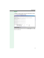
Installing the Program
1. Unpack the file fdt_optipoint_1047194.zip in a random directory.
2. Open the install.htm file in this directory
A security warning appears. Close this warning with "Grant access
for this session", for example“
.
3. Click Start Installer for Windows....
4. Click Next.
5. Confirm the licensing agreement with Next.
6. Confirm the predefined installation directory for the Deployment Tool
or select and confirm another directory.
7. Select a group and click Install.
8. Click Done to complete the installation routine.
Starting the Program
Start the program with Start → Program Files → Deployment Tool →
Deployment Tool.
7
Listing Connected IP Phones
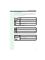
Listing Connected IP Phones
You must identify the phones you want to configure in the Deployment
Tool before you can proceed with configuration. A scan function searches
the network and creates a list of devices found. You can scan for an IP
phone on the basis of its IP address or you can scan an IP address range
for optiPoint phones.
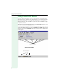
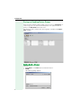
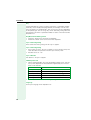
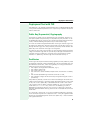
When you activate the Deployment Tool, a blank Device List appears if you
have not already saved a deployment file.
If the Deployment Tool opens with the last deployment file saved, you can
create a new deployment file by selecting New from the Edit menu on the
menu bar or by entering CTRL+N. You can also load a specific deployment
fileÆ page 16.
Menu bar
Toolbar
Column headers
Device List window
Selection boxes
8
Listing Connected IP Phones
Icons and Buttons
On-screen tips explain the meaning of interface icons or buttons when you
point directly to an object. The tip appears briefly after two seconds.
Icons in the Device_List window
For the functions New, Open and Save in the File
menu.
For the functions Add and Delete in the Edit menu.
For the functions Start and Stop in the Scan menu.
For the function Configure selected devices in the
Configure menu.
Icons in the Operations window
For the function Save in the File menu.
For the function Configure in the Operations menu.
For the functions Start and Stop in the Operations menu.
Buttons
Switch to the Device_List window.
Switch to the Operations window to configure individual devices or groups.
Switch to the Log window with the log file.
9
Listing Connected IP Phones
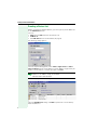
Creating a Device List
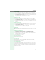
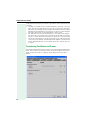
Before searching for optiPoint phones, you must specify the IP addresses
in the Add Devices mask.
Call with
• Add from the Edit menu on the menu bar or
• CTRL+A or
• the Add devices icon on the toolbar (Æ page 9)
The following dialog appears:
Click the required dialog option, either Add a single device or Add a
range of devices. Enter an IP address or an IP address range which you
want to scan for devices. Confirm you input with Add.
Overlapping ranges are not permitted. However, you can enter an IP
address as an address range, for example
192.168.1.105 to 192.168.1.105.
A table is displayed in the Device_List window.
Close the Add Devices dialog with Quit if you do not want to add any
more IP addresses.
10
Listing Connected IP Phones
Specifying the Number of Scans
You can specify the number of scans for a LAN-based scan or mark the
scan as continuous. Select the required option under Scan parameters.
You can select the maximum number of scans in the drop-down list or select "Continuous" for non-stop scanning.
There are two reasons for entering multiple scans:
1. An optiPoint is not fully installed or is in "Local mode" and is therefore
unable to answer while the scan is in progress.
2. The scan process uses the UDP protocol that does not guarantee to
forward the solicitation message or deliver a reply. Under these circumstances, multiple scans are more effective in certain network environments.
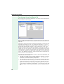
Hiding List Columns
You can hide and display columns before or after the scan. Click the View
drop-down menu on the menu bar and select or deselect the required option.
The MAC address option is not selected in this example so the column is
hidden.
11
Listing Connected IP Phones
Moving List Columns
To move a column in the list, click the column header and, holding the
mouse button down, drag the column to the new position. For example,
you could move the User ID column right and reposition it beside the Version column.
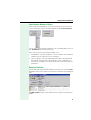
Editing a Device List
Starting a Scan
Call with
• Start from the Scan menu on the menu bar or
• the Scan Device list icon on the toolbar (Æ page 9)
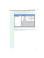
The device list is created while the scan is in progress. The number of columns depends on the options marked in the View list (Æ page 11).
The actual scan status is displayed in the table (see also Æ page 33).
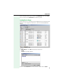
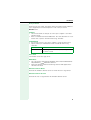
Column Contents
The "scanned" entries are sorted by IP address. You can order the list differently by briefly pointing to the column header you want to use as the
sort criteria for the table. For example, if you click the header of the Device
type column, the table will be sorted by device type.
12
Listing Connected IP Phones
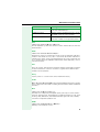
Address
The meaning of the icons in the address column is as follows:
Indicates an individual address.
Indicates the lower threshold of an IP address range.
Indicates the upper threshold of an IP address range.
Indicates a device found.
Status
The status column can contain the following values:
Not scanned
The tool made no attempt to set up a connection to
this device.
Scanning...
Temporary status during which the program tries to
set up a connection to the device.
No route
There is no IP route to this address.
No response
There was no answer from the device.
Unsuitable device An unrecognized device answered.
Ready
A recognized device answered.
MAC address
This column contains the hardware address of the device.
E.164
This column contains the terminal number for calling up the device (for example not for the UP0/E device type).
User ID
H323 ID (not read out for HiPath 4000).
Version
Specifies the current software version of the device.
13
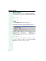
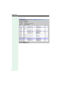
Listing Connected IP Phones
Device type
The Device type column lists the optiPoint devices each with an assigned
icon. This column could look as follows in another network:
If you hid the Device type column (Æ page 11) and the list contains different device types, the following message will prompt you to display the column after the scan:
If you do not display the Device type column, you will be unable to configure any devices as the Configure Selected Devices function will not be
available Æ page 17.
Stopping a Scan
You can interrupt a scan at any time. Call with Stop from the Scan menu
on the menu bar.
Resetting the Scan Result
If the result is unsatisfactory, for example, or if you want to change or extend the IP address range, you can reset the values in the current device
list. Call with Reset from the Scan menu on the menu bar.
14
Listing Connected IP Phones
Deleting an Entry from the Device List
If you are unable to configure a device in the list, you can delete this entry.
Select the required entry in the list with a click.
Delete with
• Delete from the Edit menu on the menu bar or
• the Delete selected Device icon on the toolbar or (Æ page 9)
• the Delete key.
The entry is deleted without further confirmation.
Selecting a Device Group
You can select three groups or use the pointer to select individual entries
at random in the device list for the operation you want to perform, such as
deletion or the Configure Selected Devices function.
Select with
• Select all Ready from the Edit menu on the menu bar or
• CTRL+R or
• Select all No Response from the Edit on the menu bar or
• Select all from the Edit menu on the menu bar or
• click a device or
• click an initial device and, holding down CTRL key, click additional randomly listed devices or
• click an initial device and, holding down the SHIFT key, select multiple
consecutive devices.
Saving a Deployment File
If you specified addresses or address range(s), you can save the result for
future use.
Save with
• Save as... from the File menu on the menu bar if you want to save the
deployment file under a specific name or Save if you want to save it
under the current name (only when changing IP addresses), or
• the Save icon on the toolbar (Æ page 9) to save the file under the current name (only when changing the IP addresses) or
• CTRL+S (only when changing the IP addresses).
The tool only saves the contents of the Address and Status columns.
15
Listing Connected IP Phones
Loading the Deployment File
The Deployment Tool opens with the last deployment file saved and displays the device list with data in the Address and Status columns only. A
blank window appears if there is no list available. You can load a specific
list if there is more than one saved.
Call with
• Open from the File menu on the menu bar or
• CTRL+O or
• the Open icon on the toolbar (Æ page 9).
The open deployment file contains the following device list, for example:
Run a scan now to enter the devices Æ page 12.
16
Configuration
Configuration
Preparation
You can configure a single device or devices that belong to the same device type. Select one or more devices of the same type Æ page 15. These
devices should be in Ready status (Æ page 13). Now, transfer the selected
devices to the Operations window:
Call with
• Configure selected devices from the Configure menu on the menu
bar or
• CTRL+C or
• the Configure selected devices icon on the toolbar (Æ page 9)
If you want to transfer additional devices to the window now, you are
asked if you want to replace existing devices or add new ones.
Configuration
Press the Operations button now to switch to the Operations window
(Æ page 9).
17
Configuration
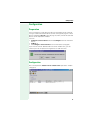
Starting Configuration
Call with
• Configure from the Operations menu on the menu bar or
• CTRL+C or
• the Configure operations icon on the toolbar (Æ page 9).
The Operations Configuration dialog for this device type appears. It contains a number of function-specific tabs.
File Transfer tab:
Tabs
Parameter value
Options
The Deployment Tool cannot read out telephone data and consequently,
does not display an existing configuration – only blank fields are shown.
18
Configuration
Dialogs for optiPoint telephones
Device-type dialogs are provided for the following optiPoint phones:
• optiPoint 400 standard Release 3 (Æ page 27)
• optiPoint 410 standard HFA (Æ page 27)
• optiPoint 400 standard SIP V2.3/V2.4/V3.0 (Æ page 28)
• optiPoint 400 economy HFA (Æ page 27)
• optiPoint 410 standard HFA (Æ page 30)
• optiPoint 410 advance HFA (Æ page 30)
• optiPoint 410 economy HFA Æ page 30
• optiPoint 410 entry HFA (Æ page 30)
• optiPoint 600 office UP0/E (Æ page 31)
• optiPoint 600 office HFA (Æ page 31)
• optiPoint 600 office SIP V2.x (Æ page 32)
19
Configuration
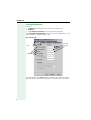
Editing a Configuration
Call up the configuration of the selected optiPoint type. Before you can enter a value in a field in the Setting column, you must mark the matching
option in the Parameter column. Values entered in the Setting column are
not sent to the devices if you did not mark the matching option in the Parameter column.
Switch to a different tab by clicking the required tab header. For information
on the tabs and parameters that you can process for a device type, see the
section on optiPoint types Æ page 27 and the section on Tabs
Æ page 36.
Example:
Confirm the dialog with OK after entering the necessary parameter values
for this device type in all tabs (Æ page 27).
Alternatively, you can use
• Reset all to delete all values in the Setting column and at the same
time remove all markings in the Parameter column.
(Reset all applies to all tabs).
• Or quit the dialog with Cancel without applying the settings.
20
Configuration
Reset and delete actions do not effect the phone and are only performed locally on the computer.
Entries in the dialog only take effect when the data is sent to the devices.
Saving settings
Save your settings with Save or Save as... before you send the configuration to the devices.
Save with
• Save from the File menu on the menu bar to save the file under the
current name or
• the Save icon on the tool bar (Æ page 9) or
• CTRL+S or
• Save as from the File menu on the menu bar to save the file under a
new name or
• the F12 function key.
Depending on the terminal type, data from the "Operations Configuration" page (all directories) is included when you perform a save.
For example, if you entered "anonymous" under "FTP username" for
optiPoint 410 Standard, "test" may appear under optiPoint 410 eco.
You can consequently create a deployment file .dep for different terminal types.
Transfer file
You can perform file transfer when the Deployment Tool is active,
for example, to update software at multiple devices simultaneously.
To do this, enter the necessary parameters for downloading the update in
the File Transfer tab and mark the option Transfer file. Specify if you want
to transfer an application or an LDAP template if applicable. Enter the number of devices for the download operation and press OK.
Proceed as described under Starting transmission Æ page 23 and confirm the following dialog:
21
Configuration
The software update activates a timer. This timer is needed to determine the update status.
The timer has different runtimes depending on the telephone type.
• 3 minutes for: optiPoint 400 standard
optiPoint 400 standard HFA
optiPoint 400 advance HFA
optiPoint 400 economy HFA
optiPoint 400 standard SIP
optiPoint 410 standard HFA
optiPoint 410 economy HFA
optiPoint 410 entry HFA
• 5 minutes for:
optiPoint 600 office UP0/E
optiPoint 600 office HFA
• 10 minutes for:
optiPoint 300 advance
Transferring a Configuration
Administrator password
You must enter the administrator password before you can transfer the
configuration to the optiPoint devices for the first time after starting up the
program.
22
Configuration
Call with
• Enter admin password from the Operations menu on the menu bar or
• CTRL+P
The following dialog appears:
Enter the password (default is 123456) and confirm your entry with OK.
Starting transfer
Start with
• Start from the Operations menu on the menu bar or
• the Perform operations icon on the toolbar (Æ page 9).
If you have not already entered the administrator password, you are now
prompted to do so (Æ page 22).
The data is sent to the devices in consecutive packets. Following transmission, completed appears in the Status column for every device. Upgrading appears in the status bar if you mark the Transfer file option under File
Transfer, for example, and perform a software update.
Stopping transfer
You can stop the transfer to devices in the network at any time.
Stop with
• Stop from the Operations menu on the menu bar or
• the Stop (Start) icon on the toolbar (Æ page 9).
Log file
An event log records actions performed with the Deployment Tool and is
saved in the "Deployment Tool\Log files" directory.
The current contents are displayed in the Log window. Use the key provided to switch to the Log window.
Verification
You can spot-check the transfer result at the individual devices using their
Web servers. To do this, open your Internet browser and enter the IP address. You can check random entries over the Administrator and Administrator Settings links.
23
Configuration
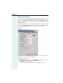
Saving and Loading Device Groups
Once you have selected a device group, you can save it in a Batch File. At
a later stage, you can select and further process this particular device
group via the Batch File in the device list.
The following shows some of the device groups available in the Operations window.
Saving Device Groups
Call with
• Save Batch... in the File menu on the menu bar or
• Ctrl+B
The following dialog appears:
24
Configuration
Select a directory and assign a name to the Batch File. Then click Save.
You can create several Batch Files for different groups.
Loading Device Groups
Create a device list or (Æ page 10) load a deployment file (Æ page 16) and
execute a scan Æ page 12). A device list similar to that displayed here
appears:
Call with
• Open Batch... in the File menu on the menu bar or
• Ctrl+B
The following dialog appears:
Select a stored Batch File with the extension ".dpb" and click Open.
25
Configuration
The relevant device group is automatically selected for further processing
in the device list.
26
optiPoint types
optiPoint types
optiPoint 400 standard H450
(Device type: 400standardH450)
Settings are made in the following tabs:
• Passwords Æ page 45
• File Transfer Æ page 38
• IP Routing Æ page 41
• Country & Language Æ page 37
• Dialling Codes Æ page 37
• Messaging Services Æ page 44
• Quality of Service Æ page 47
• Selected_Dialing Æ page 48
• SNMP Æ page 48
• Speech parameters Æ page 49
• Telephony Configuration Æ page 50
• Time Æ page 52
• Function Keys Æ page 40
optiPoint 400 economy HFA
(Device type: 400economyHFA)
Settings are made in the following tabs:
• Speech parameters Æ page 49
• Telephony Configuration Æ page 50
• Quality of Service Æ page 47
• SNMP Æ page 48
• File Transfer Æ page 38
• IP Routing Æ page 42
• Passwords Æ page 45
optiPoint 400 standard HFA
(Device type: 400standardHFA)
Settings are made in the following tabs:
• Speech parameters Æ page 49
• Telephony Configuration Æ page 50
• Quality of Service Æ page 47
• SNMP Æ page 48
• File Transfer Æ page 38
• IP Routing Æ page 42
• Passwords Æ page 45
27
optiPoint types
optiPoint 400 standard SIP
(Device type: 400 standard SIP V2.3)
Settings are made in the following tabs:
• Audio/Visual Indications Æ page 36
• Function Keys Æ page 40
• Selected_Dialing Æ page 48
• Country & Language Æ page 37
• SNMP Æ page 48
• Speech parameters Æ page 49
• Telephony Configuration Æ page 51
• Time Æ page 52
• File Transfer Æ page 38
• IP Routing Æ page 42
• Messaging Services Æ page 44
• Passwords Æ page 45
• Quality of Service Æ page 47
(Device type: 400 standard SIP V2.4)
Settings are made in the following tabs:
• Alert Indications Æ page 36
• Keyset Operations Æ page 44
• Dial Plan Æ page 37
• Country & Language Æ page 37
• Function Keys Æ page 40
• Speech parameters Æ page 49
• Telephony Configuration Æ page 51
• SIP Feature Configuration Æ page 48
• Time Æ page 52
• File Transfer Æ page 38
• IP Routing Æ page 42
• Messaging Services Æ page 44
• Passwords Æ page 45
• Quality of Service Æ page 47
• Security Æ page 47
• SNMP Æ page 48
28
optiPoint types
(Device type: 400standardSIP V3.0)
Settings are made in the following tabs:
• Passwords Æ page 45
• File Transfer Æ page 38)
• IP Routing Æ page 42
• Country & Language Æ page 37
• Quality of Service Æ page 47
• Selected_Dialing Æ page 48
• SNMP Æ page 48
• Speech parameters Æ page 49
• Telephony Configuration Æ page 51
• Time Æ page 52
• Messaging Services Æ page 44
• Function Keys Æ page 40
• Instant Messaging Æ page 40
• Contacts Æ page 36
• Kerberos Æ page 43
• Security Æ page 47
• Presence Æ page 46
29
optiPoint types
optiPoint 410 entry HFA, 410 economy HFA
(Device type: 410entryHFA, 410economyHFA)
Settings are made in the following tabs:
• Speech parameters Æ page 49
• Telephony Configuration Æ page 50
• Quality of Service Æ page 47
• SNMP Æ page 48
• File Transfer Æ page 38
• IP Routing Æ page 42
• Passwords Æ page 45
optiPoint 410 standard HFA, 410 advance HFA
(Device type: 410standardHFA, 410advanceHFA)
Settings are made in the following tabs:
• HTTP Settings Æ page 40
• WAPÆ page 52
• Miscellaneous Æ page 45
• Speech parameters Æ page 49
• Telephony Configuration Æ page 50
• Passwords Æ page 45
• Quality of Service Æ page 47
• SNMP Æ page 48
• Dialling Codes Æ page 37
• File Transfer Æ page 39
• IP Routing Æ page 42
• LDAP Æ page 44
30
optiPoint types
optiPoint 600 office HFA
(Device type: 600officeHFA)
Settings are made in the following tabs:
• Passwords Æ page 45
• Dialling Codes Æ page 37
• File Transfer Æ page 39
• IP Routing Æ page 43
• Quality of Service Æ page 47
• SNMP Æ page 48
• Speech parameters Æ page 49
• Telephony Configuration Æ page 51
• Personal Directory Æ page 46
• WAPÆ page 52
• LDAP Æ page 44
• HTTP Settings Æ page 40
optiPoint 600 officeUP0/E
(Device type: 600officeUP0/E)
Settings are made in the following tabs:
• Passwords Æ page 45
• Dialling Codes Æ page 37
• File Transfer Æ page 39
• IP Routing Æ page 43
• Quality of Service Æ page 47
• Telephony Configuration Æ page 51
• Personal Directory Æ page 46
• WAPÆ page 52
• LDAP Æ page 44
31
optiPoint types
optiPoint 600 office SIP
(Device type: 600officeSIP V2.3)
Settings are made in the following tabs:
• Passwords Æ page 45
• Dialling Codes Æ page 37
• File Transfer Æ page 39)
• IP Routing Æ page 43
• Country & Language Æ page 37
• Quality of Service Æ page 47
• Selected_Dialing Æ page 48
• SNMP Æ page 48
• Speech parameters Æ page 49
• Telephony Configuration Æ page 51
• Time Æ page 52
• Audio/Visual Indications Æ page 36
• Messaging Services Æ page 44
• Function Keys Æ page 40
• Personal Directory Æ page 46
• WAPÆ page 52
• LDAP Æ page 44
(Device type: 600officeSIP V2.4)
Settings are made in the following tabs:
• Country & Language Æ page 37
• Function Keys Æ page 40
• Key & Lamp Module 1/2 Æ page 44
• SIP Feature Konfiguration Æ page 48
• Time Æ page 52
• WAP Æ page 52
• Audio/Visual Indications Æ page 36
• Keyset Operations Æ page 44
• Dial Plan Æ page 37
• Quality of Service Æ page 47
• Security Æ page 47
• SNMP Æ page 48
• Speech parameters Æ page 49
• Telephony Configuration Æ page 51
• Dialling Codes Æ page 37
• File Transfer Æ page 39
• IP Routing Æ page 43
• LDAP Æ page 44
• Messaging Services Æ page 44
• Passwords Æ page 45
• Personal Directory Æ page 46
32
Help Functions
Help Functions
Checking the Status
The status is displayed in the header of the Device_List window before,
during, and after the scan.
Before the
scan
(example)
During the
scan
(example)
After the
scan
(example)
33
Help Functions
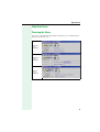
Status Messages
The following status messages may appear:
34
Ready for operations:
Number of devices available.
Connecting...
The tool is setting up a connection.
Failed to connect
The tool was unable to connect to the server.
Server busy
Device configuration is already active.
Server down
The server is unavailable.
Bad response
The device configuration service differs from the
protocol specified.
Connection lost
The connection was interrupted.
Invalid password
Incorrect password.
Operating...
Operation in progress.
Engaged
The device is in use (call or local configuration).
Rejected
The configuration service rejected the entire processing request.
Partially rejected
The configuration service partially rejected the processing request.
Upgrading...
Transferring upgrade software.
Download failed
The application download failed.
Same software
The device was upgraded without difficulty but now
has the same software version as before.
Completed
No update problems encountered.
Help Functions
Log File
Click Log. The window changes to display the current log file. This file is
automatically created and features the current system time in its name,
for example 05_Aug_2003-10_58_30.log.
You can use the current log file or create a new one for the next scan. To
create a new log file, close the current file with Close log file from the File
menu on the menu bar.
35
Configuration Tab
Configuration Tab
Alert Indications
Alert Indications (400 standard SIP V2.4, 600 office SIP V2.4)
Parameter
Setting
Alert (1 to 15)
Æ page 53
Tag (1 to 15)
Æ page 69
Ringer Melody (1 to 15)
Æ page 64
Ringer Sequence (1 to 15)
Æ page 64
Tone_Duration (secs) (1 to 15)
Æ page 69
Audio/Visual Indications
Audio/Visual Indications (400 standard SIP V2.3, 600 office SIP V2.3)
Parameter
Setting
Alert (1 to 15)
Æ page 53
Tag (1 to 15)
Æ page 69
Ringer Melody (1 to 15)
Æ page 64
Ringer Sequence (1 to 15)
Æ page 64
Tone_Duration (secs) (1 to 15)
Æ page 69
Contacts
Contacts (400 standard SIP V3.0)
36
Parameter
Setting
Admin Contacts
Æ page 53
Configuration Tab
Country & Language
Country & Language (400 standard H450, 400 standard SIP V2.x/
SIP V3.0, 600 office SIP V2.x)
Parameter
Setting
Language
Æ page 60
Country
Æ page 55
Dialling Codes
Dialling Codes (400 standard H450, 410 standard HFA,
410 advance HFA, 600 office HFA, 600 office UP0/E,
600 office SIP V2.x)
Parameter
Setting
External access code #
Æ page 57
International dial prefix #
Æ page 59
Country code #
Æ page 55
National dial prefix #
Æ page 62
Area code #
Æ page 54
Location code #
Æ page 61
Domain access code # *
Æ page 56
*.
For 400 standard H450 only.
Dial Plan
Dial Plan (400 standard SIP V2.4, 600 office SIP V2.4)
Parameter
Setting
Dialplan enabled
Æ page 56
Dial Plan
Æ page 56
Download file
Æ page 56
37
Configuration Tab
File Transfer
You can read out the current software version used by your optiPoint
phones directly at the device or over the phone’s Web server.
File Transfer (400 economy HFA, 400 standard HFA, 410 entry HFA,
410 economy HFA)
Parameter
Setting
FTP Server Address
Æ page 57
FTP account
Æ page 57
FTP username
Æ page 58
FTP password
Æ page 57
File path *
Æ page 57
Software filename
Æ page 68
Transfer file
Æ page 70
*.
For 400 standard HFA only.
File Transfer (400 standard H450, 400 standard SIP 2.x/SIP 3.0)
Parameter
Setting
FTP Server Address
Æ page 57
Fileserver address
38
FTP account
Æ page 57
FTP username
Æ page 58
FTP password
Æ page 57
File path
Æ page 57
Software filename
Æ page 68
Config filename prefix
Æ page 55
MoH filename
Æ page 62
Transfer file
Æ page 70
Configuration Tab
File Transfer (410 standard HFA, 410 advance HFA)
Parameter
Setting
FTP Server Address
Æ page 57
FTP account
Æ page 57
FTP username
Æ page 58
FTP password
Æ page 57
Software filename
Æ page 68
DSM application filename
Æ page 57
Screen saver filename
Æ page 65
LDAP filename *
Æ page 61
Java midlet filename
Æ page 59
Transfer file
Æ page 70
*.
In this case, LDAP template name.
File Transfer (600 office HFA, 600 office UP0/E, 600 office SIP V2.x)
Parameter
Setting
FTP Server Address
Æ page 57
FTP account
Æ page 57
FTP username
Æ page 58
FTP password
Æ page 57
File path
Æ page 57
Software filename *
Æ page 68
MoH filename **
Æ page 62
Loge filename **
Æ page 62
LDAP template name
Æ page 61
LDAP Folder ***
Æ page 61
Java midlet filename **
Æ page 59
JAVA Folder **
Æ page 59
Transfer file
Æ page 70
*. Not for 600 office SIP V2.4.
**. For 600 office SIP V2.4 only.
***. For 600 office HFA only.
39
Configuration Tab
Function Keys
Function Keys (400 standard H450, 400 standard SIP V2.x/SIP V3.0,
600 office SIP V2.x)
Parameter
Setting
Key (1 to 10 or 17)
Æ page 60
HTTP Settings
HTTP Settings (410 standard HFA, 410 advance HFA, 600 office HFA)
Parameter
Setting
HTTP gateway/proxy address
Æ page 58
Port Number
Æ page 63
Instant Messaging
Instant Messaging (400 standard SIP V3.0)
40
Parameter
Setting
Admin Instant Messaging
Æ page 53
IM Session Timer (secs)
Æ page 59
Preformed Instant Messages
Æ page 63
Configuration Tab
IP Routing
IP Routing (400 standard H450)
Parameter
Setting
DHCP
Æ page 56
Default gateway
Æ page 56
Route 1
Æ page 65
Gateway 1
Æ page 58
Mask 1
Æ page 62
Route 2
Æ page 65
Gateway 2
Æ page 58
Mask 2
Æ page 62
LAN port mode
Æ page 60
PC port mode
Æ page 60
41
Configuration Tab
IP Routing (400 economy HFA, 400 standard HFA, 410 entry HFA,
410 economy HFA, 410 standard HFA, 410 advance HFA,
400 standard SIP V2.x/SIP V3.0)
Parameter
Setting
DHCP
Æ page 56
Default gateway
Æ page 56
Route 1
Æ page 65
Gateway 1
Æ page 58
Mask 1
Æ page 62
Route 2
Æ page 65
Gateway 2
Æ page 58
Mask 2
Æ page 62
DNS server address
Æ page 56
Secondary DNS server address * Æ page 65
DNS domain name
Æ page 56
LAN port mode **
Æ page 60
PC port mode ***
Æ page 60
*. For 400 standard SIP V2.4 and SIP V 3.0 only.
**. Not for 400 standard SIP V3.0.
***.Not for 400 standard SIP V3.0, 410 entry HFA, 410 economy HFA, 400 economy HFA.
42
Configuration Tab
IP Routing (600 office HFA, 600 office UP0/E , 600 office SIP V2.x)
Parameter
Setting
DHCP
Æ page 56
Default gateway
Æ page 56
Route 1
Æ page 65
Gateway 1
Æ page 58
Mask 1
Æ page 62
Route 2
Æ page 65
Gateway 2
Æ page 58
Mask 2
Æ page 62
DNS server address
Æ page 56
Secondary DNS server address * Æ page 65
DNS domain name
Æ page 56
LAN port mode**
Æ page 60
*. For 400 standard SIP V2.4 and SIP V 3.0 only.
**. LAN port 1 mode and LAN port 2 mode.
Kerberos
Kerberos (400 standard SIP V3.0)
Parameter
Setting
Kerberos Server Address
Æ page 59
Kerberos Server Port
Æ page 59
Windows Domain Name
Æ page 71
Windows Domain User ID
Æ page 71
New Domain Password
Æ page 62
User Change Password
Æ page 70
43
Configuration Tab
Keyset Operations
Keyset Operations (400 standard SIP V2.4, 600 office SIP V2.4)
Parameter
Setting
Originating line preference
Æ page 62
Terminating line preference
Æ page 69
Line Key action mode
Æ page 61
Registration LEDs
Æ page 64
Rollover type
Æ page 65
Server type
Æ page 66
Key & Lamp Module 1/2
Key & Lamp Module 1/2 (600 office SIP V2.4)
Parameter
Setting
Key (1 to 16)
Æ page 60
LDAP
LDAP (410 standard HFA, 410 advance HFA, 600 office HFA,
600 office UP0/E, 600 office SIP V2.x)
Parameter
Setting
Server address
LDAP Server Addr
Æ page 61
Port number
LDAP Server Port Number
Æ page 61
Messaging Services
Messaging Services (400 standard H450, 400 standard SIP V2.x/
SIP V3.0, 600 office SIP V2.x)
44
Parameter
Setting
Message centre #
Æ page 62
Voice mail #
Æ page 71
Configuration Tab
Miscellaneous
Miscellaneous (410 standard HFA, 410 advance HFA)
Parameter
Setting
Help Internet URL
Æ page 58
Passwords
Passwords (400 standard H450, 400 standard HFA,
400 economy HFA, 400 standard SIP 2.x/SIP 3.0)
Parameter
Setting
Admin password
Æ page 53
Passwords (410 etry HFA, 410 economy HFA, 410 standard HFA,
410 advance HFA)
Parameter
Setting
Admin password
Æ page 53
Actions
Æ page 53
Passwords (600 office HFA, 600 office UP0/E, 600 office SIP V2.x)
Parameter
Setting
Admin password
Æ page 53
User password
Æ page 71
45
Configuration Tab
Personal Directory
Personal Directory (600 office HFA, 600 office UP0/E,
600 office SIP V2.x)
Parameter
Setting
Server address
Æ page 57
File path
Æ page 57
Filename
Æ page 57
Username
Æ page 58
Password
Æ page 57
Account name
Æ page 53
Import personal directory
Æ page 59
Presence
Presence (400 standard SIP V3.0)
46
Parameter
Setting
Presence Publishing
Æ page 63
Presence Watching
Æ page 63
Proximity Timer (secs)
Æ page 63
Ring Seen Timer (secs)
Æ page 65
Ring No Reply Timer (secs)
Æ page 65
Unused Timer (secs)
Æ page 70
Configuration Tab
Quality of Service
Quality of Service (400 standard H450, 400 standard HFA,
400 economy HFA, 410 entry HFA, 410 economy HFA,
410 standard HFA, 410 advance HFA, 600 office HFA,
400 standard SIP V2.x/SIP V3.0, 600 office SIP V2.x)
Parameter
Setting
Layer 3
Æ page 64
Layer 3 Signalling
Æ page 60
Layer 3 Voice
Æ page 60
Layer 2
Æ page 64
Layer 2 Signalling
Æ page 60
Layer 2 Voice
Æ page 60
Layer 2 Default
Æ page 60
VLAN Method*
Æ page 71
VLAN Id
Æ page 71
*.
Not for 400 economy HFA and 400 standard H450
Quality of Service (600 office UP0/E)
Parameter
Setting
VLAN Method
Æ page 71
VLAN Id
Æ page 71
Security
Security (400 standard SIP V2.4/SIP V3.0, 600 office SIP V2.4)
Parameter
Setting
Key Material File Management
Æ page 60
Trusted Certificates File Management Æ page 70
Probe If Allow *
*.
Æ page 63
Not for 600 office SIP V2.4.
47
Configuration Tab
Selected_Dialing
Selected_Dialing (400 standard H450, 400 standard SIP V2.3/
SIP V3.0, 600 office SIP V2.3)
Parameter
Setting
Key 1 to 10 or 17
Æ page 60
SIP Feature Configuration
SIP Feature Configuration (400 standard SIP V2.4,
600 office SIP V2.4)
Parameter
Setting
Group pickup URI
Æ page 58
Auto answer
Æ page 54
Beep on auto answer
Æ page 54
Auto reconnect
Æ page 54
Beep on auto-reconnect
Æ page 54
Permit Decline Call *
Æ page 63
*. For 600 office SIP V2.4 only.
SNMP
SNMP (400 standard H450, 400 standard HFA, 400 economy HFA,
400 standard SIP V2.x/SIP V3.0, 410 entry HFA, 410 economy HFA,
410 standard HFA, 410 advance HFA, 600 office HFA,
600 office SIP V2.x)
48
Parameter
Setting
Trap listener address
Æ page 68
SNMP password
Æ page 67
Configuration Tab
Speech parameters
Speech parameters (400 standard H450, 400 standard HFA,
400 economy HFA, 600 office HFA)
Parameter
Setting
Audio mode
Æ page 54
Jitter buffer *
Æ page 59
*.
Not for 600 office HFA.
Speech parameters (410 entry HFA, 410 economy HFA,
410 standard HFA, 410 advance HFA)
Parameter
Setting
Audio mode
Æ page 54
Compression Codec
Æ page 55
Silence Suppression
Æ page 66
Speech parameters (400 standard SIP V2.x/SIP V3.0,
600 office SIP V2.x)
Parameter
Setting
Audio mode
Æ page 54
Compression Codec
Æ page 55
Silence Suppression
Æ page 66
Jitter buffer *
Æ page 59
RTP Packet Size **
Æ page 65
*. Not for 600 office SIP V2.x.
**. For 400 standard SIP 2.x and 600 office SIP V2.4 only.
49
Configuration Tab
Telephony Configuration
Telephony Configuration (400 standard H450)
Parameter
Setting
System type
Æ page 69
Gatekeeper address
Æ page 58
Gatekeeper id
Æ page 58
H323 gateway address
Æ page 58
Gatekeeper discovery address Æ page 58
Mobility
Æ page 62
Emergency number
Æ page 57
H450 features
Æ page 58
Security profile
Æ page 66
Security window (seconds)
Æ page 66
Time to live (minutes)
Æ page 69
Migration flag
Æ page 62
Telephony Configuration (400 standard HFA, 400 economy HFA)
Parameter
Setting
PBX/Gateway Address
Æ page 63
Telephony Configuration (410 entry HFA, 410 economy HFA,
410 standard HFA, 410 advanceHFA)
50
Parameter
Setting
PBX/Gateway Address
Æ page 63
System type
Æ page 69
Emergency number
Æ page 57
Cancel mobility password
Æ page 54
Base PBX Port
Æ page 63
Location ID number
Æ page 61
Configuration Tab
Telephony Configuration (400 standard SIP V2.x/SIP V3.0,
600 office SIP V2.x)
Parameter
Setting
SIP Routing Model
Æ page 67
SIP Transport
Æ page 67
Register by name
Æ page 64
Outbound proxy
Æ page 62
SIP Server Address
Æ page 67
SIP Server Port *
Æ page 67
SIP Gateway Address
Æ page 66
SIP Gateway Port *
Æ page 66
SIP Registrar Address
Æ page 67
SIP Registrar Port *
Æ page 67
Beep On SIP Server Error
Æ page 54
Session Timer
Æ page 66
Session Duration (seconds)
Æ page 66
Registration Timer (seconds)
Æ page 64
Default domain name
Æ page 56
Realm 1
Æ page 64
Emergency number
Æ page 57
System name (max 10 ch) **
Æ page 68
*. For 600 office SIP V2.4 only.
**. For 400 standard SIP V2.x only.
Telephony Configuration (600 office HFA, 600 office UP0/E)
Parameter
Setting
PBX/Gateway Address *
Æ page 63
Status message transfer *
Æ page 68
Operating mode
Æ page 62
*. Not for 600 office UP0/E.
51
Configuration Tab
Time
Time (400 standard H450, 400 standard SIP V2.x/SIP V3.0,
600 office SIP V2.x)
Parameter
Setting
SNTP server address
Æ page 68
Timezone offset
Æ page 69
Daylight saving
Æ page 55
Time
Æ page 69
WAP
WAP (410 standard HFA, 410 advance HFA, 600 office HFA,
600 office UP0/E, 600 office SIP V2.x)
Parameter
Setting
Gateway Address/
HTTP gateway/proxy address
Æ page 58
Port Number
Æ page 63
Home page
Æ page 58
Connection type
Æ page 55
Allow JAVA MIDlet DL via web* Æ page 53
Allow WAP Push Messages** Æ page 53
*. For 410 standard HFA, 410 advance HFA and 600 office HFA only.
**. For 600 office HFA only.
52
Parameters
Parameters
Description
Account name
Name of the FTP account requested by certain FTP servers.
Actions
You can select one of the following two options for Actions:
• Factory reset, to revert to the factory settings.
• Clear user data, to delete the user data only.
Admin Contacts
Provides users with the "Contacts" function which permits access to the
contacts stored on the Microsoft LCS.
Default: disabled.
Admin Instant Messaging
Provides users with the Instant Messaging function.
Default: disabled.
Admin password
• You can change the password needed to access the administrator area
here.
• Default password 123456.
Alert
You can specify up to 15 alerts in the Audio/Visual Indications tab. Mark the
option before entering the values for an alert.
Allow JAVA MIDlet DL via web
Specify here with Yes or No whether or not JAVA MIDlets can be loaded
via the Web interface.
Allow WAP Push Messages
Specify here with Yes or No whether or not WAP push messages should
be possible.
Application filename
• Enter the name of the file containing the optiPoint 410 software.
• The file must be saved on the Æ FTP server in a specific directory.
• Possible values: 1 to 24 characters.
53
Parameters
Area code
Enter your area code here, for example 089 for Munich.
Audio Mode
The following modes can be set:
• Æ G.711 Preferred
• Compressed Codec Preferred (Æ"page"55)
• Compressed Codec Always (Æ"page"55)
Auto answer
Auto answer. You can enable or disable this function.
Auto reconnect
This function allows you to reconnect calls automatically. You can enable
or disable this function.
Beep on auto answer
Beep on auto answer. You can enable or disable this function.
Beep on auto-reconnect
Beep on auto-reconnect of queued calls. You can enable or disable this
function.
Beep On SIP Server Error
Beep on error can be enabled or disabled. The option is enabled by default.
Cancel mobility password
You can now deregister the telephone connection at the "Guest Telephone"
if you forgot to do this earlier on.
Enter the "Mobility cancel pw" and confirm your input. This reactivates the
"home connection" allowing you to make calls again.
54
Parameters
Codec
• Select the audio transfer principle you want use here.
•
Codec
Audio Mode
High Quality
Preferred
Uncompressed voice Use uncompressed voice
transmission.
transmission (Æ G.711,
Æ G.722). Suitable for
broadband intranet connections.
Use
Low Bandwidth
Preferred
Use compressed
voice transmission
preferably.
Suitable for connections
with different bandwidth
levels.
Low Bandwidth
Only/Always
Use
compressed voice
transmission only.
Suitable for connections
with low bandwidth.
Please refer to the user manuals supplied with various optiPoint
phones for information on the relevant defaults.
Compression Codec
You can currently only set the value Æ G.723.
Connection type
See Æ WAP Mode.
Config filename prefix
Name of the configuration file without extension.
Country
Select the required country in the drop-down list.
Country code
Enter your country code here, for example 049 for Germany.
Daylight saving
To enable/disable "Sommerzeit". Daylight saving is disabled by default.
• Manual definition is only necessary if this information is not automatically transmitted (for example by the Æ PBX or an Æ DHCP server).
• Activate this switch if you want the tool to switch between daylight
saving and winter time.
55
Parameters
Default domain name
Enter your Æ Domain name here.
Default Gateway
• Enter the Æ IP Address that was assigned to your Æ PBX in the Default Gateway provided this value was not assigned dynamically by a
Æ DHCP server.
• If the value was assigned dynamically, it is read-only here.
DHCP
• Enable this option if you want a Æ DHCP server to assign the necessary IP data dynamically for the phone.
• Disable this option if there is no DHCP server available in the IP network. In this case, the data for the Terminal IP Address and Terminal
Mask must be manually assigned and the Æ Default Route must be
manually set.
Dialplan enabled
Select on or off to determine whether or not a Æ Dial Plan should be used.
Dial Plan and Download file
Via Browse, scan the local file system for a Æ Dial Plan to download. Select Download file to send the required Æ Dial Plan to the telephone.
DNS server address
• Only enter the Æ IP Address of the Æ DNS server here if this was not
assigned dynamically by a Æ DHCP server and you are not operating
the optiPoint device at a Æ PBX over Æ HFA.
• Default address: Blank by default.
DNS domain name
• Only enter the name of the associated Æ Domain if you cannot operate
the optiPoint device at a Æ PBX over Æ HFA.
• Default name: Blank by default.
Download Server IP Address
Enter the Æ IP Address of the Æ FTP server here so that you can upload
and download files from/to optiPoint 410.
Domain access code
Access code for Æ Domain
56
Parameters
DSM application filename
• Can only be configured for optiPoint 410 standard/advance and is only
necessary if you are using an optiPoint 410 Display Module.
• Enter the name of the file containing the optiPoint 410 Display Module
software.
• The file must be saved on the Æ FTP server in a specific directory (FTP
path/folder).
• Possible values: 1 to 24 characters.
Emergency number
Call number automatically dialed after one second.
External access code
Enter the prefix that must be entered when dialing an external call number,
for example "0".
Filename
Name under which the file you want to load is saved on the server.
File path
•
•
Enter the path to the directory that was set up on the Æ FTP server for
uploading and downloading files.
The path can contain up to 255 characters.
Fileserver address
A correctly configured Æ FTP server (file server) is always needed for exchanging data using FTP. The server program must be running on a computer (for example PC) in the same Æ LAN as the optiPoint device. Enter
the IP address of this server.
FTP account
• Enter the Æ FTP user account for access to the FTP server.
• Possible values: 1 to 24 characters.
• Default value: blank.
FTP password
• Enter the password that was set in the Æ FTP server as the password
for accessing this server. The password must be confirmed in the following field.
• The password must match the Æ FTP user name.
• Possible values: 1 to 24 characters.
• Default password: 123456.
57
Parameters
FTP username
• Enter the name that was set in the Æ FTP server as the user for accessing this server.
• The name must match the Æ FTP password.
• Possible values: 1 to 24 characters.
Gatekeeper address
Enter the IP address of the Æ Gatekeeper if known (otherwise it is entered
by "autodiscovery").
Gatekeeper discovery address
Enter the Æ IP Address for a non-HiPath Æ Gatekeeper.
Gatekeeper id
Enter the Æ Gatekeeper identifier here.
Gateway
Enter the Æ IP Address of the first or second Æ Gateway, for example, of
a HG 1500 or HG 3530 board.
Gateway address/HTTP gateway/proxy address
• This can only be configured for optiPoint 410 standard/advance, 600 office HFA, 600 office UP0/E , 600 office SIP V2.x.
• If a Æ WAP gateway is available in the network, enter the Æ IP Address of this gateway here.
Group pickup URI
Specify a URI for group pickup here.
H323 gateway address
Enter the Æ IP Address of the Æ Gateway for Æ H.323 Standard.
H450 features
Set to on if there are non-HiPath devices in the network. Call forwarding
and transfer to non-HiPath users, however, is not permitted.
Help Internet URL
• This can only be configured for optiPoint 410 standard and advance.
• Enter the file names of the optiPoint 410 online help.
Home page
Shows the WAP page configured as the "home page".
58
Parameters
Import personal directory
This option must be marked if you want to transfer a specified file with a
personal directory to the telephones.
IM Session Timer
• Contains the length of time for which the Æ EPID address of an instant
message is valid.
• 180 seconds is set by default.
International dial prefix
Enter the international dial prefix here, for example 00.
Java midlet filename
Name of the Java application for download.
JAVA folder
Name of the download directory for the Java application.
Jitter Buffer
• Select the buffer duration here (number of data packets) that changes
the effect of Æ Jitter.
•
•
•
Short
2 packets
Medium (normal)
4 packets
Long
6 packets
The more stable the network connection, the shorter the buffer time
that can be selected (less voice delay).
This accuracy of this setting depends on the frequency of data packet
transmission by terminals (for example 20ms or 120ms).
Please refer to the user manuals supplied with various optiPoint
phones for information on the relevant defaults.
Kerberos Server Address
IP address of the Æ Kerberos server.
Kerberos Server Port
Port address of the Æ Kerberos server.
59
Parameters
Key
A programmable key can be assigned a function or a speed dial number.
Some keys have already been programmed, for example, with the functions "Disconnect" or "Loudspeaker". You can use up to 17 keys depending
on the phone type. You can assign keys in the Selected_Dialing tab or the
Function Keys tab. Enter a speed dial number or select a function from the
drop-down list.
Key Material File Management
• Write File: Send server certificate to telephone.
• Delete File: Delete server certificate on the telephone.
Layer 2 Voice/Signaling
Voice connection and signaling with Æ Layer 2 support.
Layer 3 Voice/Signaling
• You can only set this if Æ Layer 3 support is active (Æ QoS L2/L3). The
value describes the position in the Æ Layer 2 Priority value.
• Possible values: 0 ... 63.
Layer 2 Default
The default is Æ Layer 2 support.
LAN/PC port mode
• Specify the bandwidths you want the optiPoint phone to use. The necessary value depends on the bandwidth supported by the switch or
router in the network.
Bandwidth
Application
10 Mbps half dup
For 10-Mbit networks in half duplex mode.
10 Mbps full dup
For 100-Mbit networks in full-duplex mode.
100 Mbps half dup For 10-Mbit networks in half duplex1 mode.
100 Mbps full dup
For 100-Mbit networks in full-duplex2 mode.
Auto negation
•
You must restart the tool after making a change.
Language
Select your language in the drop-down list.
60
Parameters
Layer 2 Priority
• You can only set this if Æ Layer 2 support is active (Æ QoS L2/L3).
• You can set a priority value between 0 and 7 for each of the 64 positions
here (priority 7: high, 0: low).
• This additional data transmission information is used for forwarding priority decisions when data arrives in a Æ Switch.
LDAP Server Addr
Also known as "LDAP Directory Server IP address" or "Server address".
• This can only be configured for optiPoint 600 office and optiPoint 410
standard/advance HFA.
• If you are using an Æ LDAP server, enter the Æ IP Address of this server here.
LDAP template name
• Enter the name of the LDAP template file that is used in connection
with the Æ LDAP server.
• The file must be saved on the Æ FTP server in a specific directory
(Æ Download Server IP Address, Æ File path).
LDAP folder
Name of the directory on the Æ FTP server where you saved the Æ LDAP
file.
LDAP Server Port Number
• Also known as Port Number. This can only be configured for
optiPoint 600 office and optiPoint 410 standard/advance HFA.
• If you are using a Æ LDAP server, enter the Æ Port number here for
communication with this server.
• Possible values: 1 ... 65535.
Line Key action mode
Reserved for future function.
Location code
Enter the location code (the call number without extension number,
for example, of your company).
Location ID number
Contains the name or number saved for the phone on the server. This is
automatically entered in optiPoint and output on the display (also known as
local id). If a name is not available, the Location identifier number (LIN) is
output on the display.
61
Parameters
Loge filename
Enter the filename of the logo (for example logo of your company) which
should be shown on the disply.
Mask
Enter the value for the network mask for Æ Mask 1 or 2. In general, this is
255.255.255.0.
Message centre
Call number of a phone messaging system.
Migration flag
Switch the flag on or off (system switchover).
Mobility
Mark if you want to support mobility.
MoH filename
Name of the Æ MoH file.
National dial prefix
Enter the national dial prefix here, for example 0.
New Domain Password
Contains the Windows password for the telephone user.
Originating line preference
Reserved for later use.
Operating mode
The following options are available:
• Auto detect
• Direct access
• LAN access
Outbound proxy
You must enable this option if you are using a "Æ Outbound Proxy Æ Proxy
server" so that you can assign it a valid domain name.
62
Parameters
PBX/Gateway Address
Enter the Æ IP address of the Æ PBX where you want to operate the optiPoint or alternatively the Æ IP address of the gateway. Set the type used.
You can only change the E.164 address by editing "E.164" directly in the
"Operations" directory and not with "Operations Configuration".
Permit Decline Call
Permit user to provide the opportunity, to do facilities in connection with
decline incoming calls.
Port Number
• This can only be configured for optiPoint 410 standard/advance and 600
office HFA, 600 office UP0/E , 600 office SIP V2.x.
• If a Æ WAP server is available, enter the Æ Port number here for communication with this server.
Preformed Instant Messages
You can enter up to 20 preformed instant messages here which you can
later select using the "Preformed Instant Messages" function.
Default: blank.
Presence Publishing
Enable or disable the "Presence Publishing" function in conjunction with a
Microsoft LCS for displaying your own presence status.
Default: disabled.
Presence Watching
Enable or disable the "Presence Publishing" function in conjunction with a
Microsoft LCS for displaying the presence status of other contacts.
Default: disabled.
Probe If Allow
You can enable or disable test server mode.
Default: disabled.
Proximity Timer
Contains the length of time in seconds during which the user is displayed
as "Present" after the telephone was used.
Default: 5 seconds
63
Parameters
PSTN acces code
Access code for the Æ PSTN telephone network.
QoS L2/L3
• The settings are based on the Æ QoS areas Æ Layer 2 and Æ Layer 3
that control the prioritization of transmitted data.
• Æ Layer 2 Priority and Virtual LAN ID (Æ VLAN ID) can be modified for
layer 2. Æ Layer 3 Voice/Signaling can be modified for layer 3.
• The activation of Æ Layer 2 and/or Æ Layer 3 support is only recommended if the Æ Switch used can interpret this information
(for example "Æ Layer 2 switch").
Realm
Display or change the SIP Realm value. SIP realm is used to identify the
phone at the SIP server.
Register by name
If this option is enabled and a terminal name is entered, this name will appear in the display in the second line on the left. The option is disabled by
default.
Registration LEDs
The LEDs illuminate when the telephone is activated. This indicates that
you have registered correctly. You can enable or disable this function with
on and off.
Registration Timer
Use this function to specify the amount of time required for logging on to
the SIP server again. Logging on again ensures that the SIP telephone remains logged onto the SIP server. This enables you to also detect any server connection problems. The timer is preassigned the value 0 and can have
a maximum value of 72 minutes.
Ringer Melody
Select the Ringer Melody for the current alarm to be set in the Audio/Visual
Indications tab. You can set the following values:
• silent or
• level 1 to 8
Ringer Sequence
Select the Ringer Sequence for the current alarm to be set in the Audio/
Visual Indications tab. You can set the levels 1 to 3.
64
Parameters
Ring No Reply Timer
Configurable time in seconds after which the ringing status is displayed for
a telephone. When the phone rings, its status is IDLE until the Ring Seen
Timer expires. Once the timer has expired, the telephone displays its
"Ringing" status.
Ring Seen Timer
Configurable time in seconds after which the "Presence" status is displayed for the telephone. For example, if the time is set to five seconds,
this means that the "Absent" status is displayed if a call rings for more than
five seconds.
Rollover type
How should a trunk key react if a trunk is busy and the call is signalled at a
second trunk? The following options are available:
• No ring
• Alert ring
Route
Enter the first or second destination address preset for a Æ Router.
RTP Packet Size
The packet size is entered as a time unit. You can select the values auto,
10 ms and 20 ms.
Screen saver filename
• This cannot be configured for all optiPoint phones.
• Enter the name of the file that you want to use as your screen saver.
• The file must be saved on the Æ FTPserver in a specific directory.
• Valid file types: GIF, JPG.
Secondary DNS server address
Alternative address to Æ DNS server address.
65
Parameters
Security profile
You should define the Æ Security protocol setting if the optiPoint 400 standard is connected to a HiPath 5000 system.
Three settings are available:
• off (voice encryption is disabled).
• reduced (voice encryption on one side only – Æ Gatekeeper encrypts
data sent).
• on (voice encryption on both sides – Æ IP phone and Æ Gatekeeper
encrypt data sent)
Security window (seconds)
A time window is used if the IP phone is connected to a HiPath 5000 system and Æ Security profile is activated (reduced or on). The tool only accepts messages from the Æ Gatekeeper that arrive within the defined
time window. The highest value you can enter here is 120 minutes.
Server type
In the list field, specify the communication system. The following options
are available:
• Other
• HiQ8000
• Broadsoft
• Sylantro
The default is Other.
Session Duration (minutes)
Enter a maximum duration in minutes for a session here.
Session Timer
Switches the SIP Session timer on and off. The timer controls the duration of a session.
Silence Suppression
The option can be enabled or disabled.
SIP Gateway Adress
Enter the Æ IP Address of the SIP gateways if gateway mode is in use.
SIP Gateway Port
Enter the Æ Port number for communicating with the SIP Gateway.
66
Parameters
SIP Registrar Address
Enter the corresponding Æ IP Address here.
SIP Registrar Port
Enter the Æ Port number for communicating with the SIP Registrar.
SIP Routing Model
Enter the preferred routing model here. The default value is server mode.
In server mode the telephone uses the Æ IP Address entered to log on to
the SIP server. A dial tone sounds after successful logon.
In gateway mode, the telephone generates a dial tone without logon and
routes all calls to the SIP gateway configured Æ IP Address.
Æ IP Address is the only option available in direct mode. This mode is
used mainly for test purposes.
SIP Server Address
Enter the Æ IP Address of the SIP server if server mode is active.
SIP Server Port
Enter the Æ Port number for communicating with the SIP Server.
SIP_Transport
You can select the setting Æ UDP or Æ TCP for the SIP transport.
SNMP Password
• Enter the password that was set in the Æ SNMP server as the password for accessing this server.
• The password must contain between 1 and 24 characters.
• Default password: see Æ Password.
67
Parameters
SNMP Trap IP Address
This is the IP address of the SNMP Manager to which the telephone reports every new start. This is known as a Trap listener address.
• If an Æ SNMP server is available in the network, enter the Æ IP Address of this server here.
• Default address: See the description of the "default values for optiPoint"
in the various user manuals.
SNMP Trap Port
• Specify the Æ Port you want to use for transferring Æ SNMP error
messages.
SNTP Server IP Address
• If an Æ SNTP server is available in the network, enter the Æ IP Address
of this server here.
• Default address: see the description of the "default values for optiPoint"
in the various user manuals.
Status message transfer
This option controls whether or not the telephone can receive and display
status messages.
Software filename
Name of the software you want to download from the FTP server (File
server).
Possible values: 1 to 24 characters.
Subscriber Number
• Enter the subscriber number for the optiPoint phone here.
• The number can contain between 1 and 24 digits.
• This is the number that is used as the internal call number.
Subscriber Password
• Enter a Æ Password with between 6 and 20 digits.
• There is no default password set.
System name
Enter the name of the communications platform used.
68
Parameters
System type
• Enter HiPath GK if the system environment is HiPath 5000.
• Enter Non-HiPath GK if you are using a third-party Æ Gatekeeper.
• Enter Æ Gateway if you are using a HiPath HG 1500.
• Enter Direct if you are using IP dialing and no Æ Gatekeeper.
• In optiPoint 410 standard/economy/entry HFA, you can choose between HiPath 4K V1.x, HiPath 4K V2.x and HiPath 3K V4.0.
Tag
Enter the required tag for the current alarm to be set in the Audio/Visual
Indications tab.
Terminating line preference
Reserved for later use.
Time
• You should only mark this option if this information is not automatically
transmitted (for example by the Æ PBX or an Æ DHCP server).
• If this option is marked, the computer’s system time is applied.
Time to live (minutes)
Use this function to specify the interval at which the telephone should
send a signal to the Æ Gatekeeper (every time one third of the time set
elapses). If the "Time to live" value is set to three minutes, for example, the
telephone sends a signal every minute.
The highest value you can set is 4320 seconds, that is, three days.
Timezone offset
• You should only enter data here if an Æ SNTP server provides time information.
• The data describes the offset in hours compared to time information of
the SNTP server.
Tone_Duration
Enter the duration of the tone in seconds for the current alarm to be set in
the Audio/Visual Indications tab.
69
Parameters
Transfer file
This option must be marked if you want to transfer a specified file to the
telephones or from the telephones. Mark the appropriate options in the following selection.
•
•
•
•
DL Application
DL Config file
UL Config file
DL MoH file (Music on Hold)
or
•
•
•
•
DL Application
DL DSM Application
DL Æ LDAP template
DL Screen Saver
or
•
•
•
•
•
DL Application
DL DSM Application
DL Æ LDAP template
DL Screen Saver
DL JAVA Midlet
or
•
•
•
DL Application
DL Æ LDAP template
DL JAVA Midlet
or
•
DL Application
Trusted Certificates File Management
• Write File: Send trusted certificate to telephone.
• Delete File: Delete trusted certificate on telephone.
Unused Timer
Contains the length of time after which the "Presence" status is displayed
if the telephone is not used during this time.
Default: disabled.
User Change Password
The telephone user is permitted to change the user password.
Default: enabled.
70
Parameters
User password
Reset the user password. This option allows the administrator to delete a
user’s forgotten password and replace it with a new password.
Default: blank
VLAN Id
• The virtual LAN ID can only be set if Æ Layer 2 support is activated
(Æ QoS L2/L3).
• Enter a value between 0 and 4095 here. This value describes an association with a specific Æ VLAN when using Æ VLANs.
VLAN Method
• You can only set this if Æ Layer 2 support is active (Æ QoS L2/L3).
• Specify where you should retrieve the Æ VLAN Id when using
Æ VLANs.
Manual
The ID entered under Æ VLAN Id is used.
DHCP
When using a Æ DHCP server, the ID supplied by
this server is used.
Voice mail
Call number of the message server.
WAP Mode
• This can only be configured for optiPoint 410 standard and 600 office
HFA, 600 office UP0/E, 600 office SIP V2.x.
• Select the protocol used for transferring data for WAP applications:
Æ HTTP or Æ WSP.
Windows Domain Name
Name of the Windows domain server at which the user is registered.
Windows Domain User ID
Name of the user as registered at the Windows domain server.
71
Abbreviations and Technical Terms
Abbreviations and Technical Terms
You will find additional information in the relevant literature on network
technology and Æ VoIP.
Default Route
A default route is a route that is suitable for every destination address. In
other words, the route can be used for every destination address. The default route has the lowest priority and is only used if no other routes are
suitable. Essentially, a route specifies the path that the two packets should
or can travel for transport within the network. The default route is used if
a path is not prescribed or known.
DHCP
Abbreviation of "Dynamic Host Configuration Protocol."
Dynamic assignment of IP addresses for subscribers in an IP network using a central DHCP server.
Dial Plan
Contains a dial plan which can be used to determine when a call number
is complete.
DNS
Abbreviation of "Domain Name Service."
The DNS service converts an alphanumeric name query (for example
alp.dillingen.de) into an IP address.
Large InterNIC primary name servers and the national registration centers
(for example: DE-NIC for Germany) have database servers for this purpose,
in which the IP addresses are assigned host names.
Domain
A domain is a logical association of computers and can be split into subdomains. DNS servers are used for resolving domain names. An example of
a domain name is www.microsoft.com. Here, . stands for the ROOT of the
DNS server, com for the commercial top-level domain,microsoft for the
company, and www for the server area. Domain names are resolved from
right to left.
Download Firmware
• Use this function to download an updated software version from the
Æ FTP server for the optiPoint 410.
• You must set the following parameters before the download:
Æ Download Server IP Address, Æ File path, Æ Application filename,
Æ Account name, Æ FTP username, Æ FTP password
72
Abbreviations and Technical Terms
E.164
Standardized call numbers according to the ITU’s international numbering
plan with up to 15 digits. Usually composed of the parts: Country Code
(CC), National Destination Code (NDC) and Subscriber Number (SN).
EPID
Abbreviation of End Point IDentifier. Hardware address of an incoming
message.
FTP
Abbreviation of "File Transfer Protocol."
Used for transferring files in networks to update telephone software,
for example (Æ Download Firmware).
G.711
Audio protocol for uncompressed voice transmission. Requires a bandwidth of 64 Kbps.
G.722
Audio protocol for uncompressed voice transmission. Requires a bandwidth of 64 Kbps.
G.723
Audio protocol for compressed voice transmission. The quality is poorer
than Æ G.711 and Æ G.729. Requires a bandwidth of 6 Kbps.
G.729
Audio protocol for compressed voice transmission. The quality is poorer
than Æ G.711 and better than Æ G.723. Requires a bandwidth of 8 Kbps.
Gatekeeper
A gatekeeper is a logical Æ H.323 Standard component which can be implemented as Windows or UNIX software, as a router option, as part of an
Æ MCU or a Æ Gateway.
Gateway
A system (computer or board) that transfers data between different networks. Gateways coordinate different protocols as appropriate,
for example, Æ IP network and ISDN network. A gateway can contain a
Æ Router at the same time.
73
Abbreviations and Technical Terms
H.323 Standard
Consist of the following components (minimum):
• Terminals
• Æ Gateways
• Æ Gatekeeper
• Multipoint Control Units (Æ MCUs)
HFA
Abbreviation of "Hicom Feature Access“ or "HiPath Feature Access“
.
Represents the gateway-based connection (for example HG 1500 or
HG 3530) betweenÆ IP telephony and a Æ PBX.
HTTP
Abbreviation of "Hypertext Transfer Protocol."
Protocol for transmitting data in Æ IP networks.
Identification Server
The HiPath system’s Identification Server is used for the remote identification of telephones. The transport address (Æ IP Address and port) of the
Identification Server must be entered for this in the telephone. The transport address is only entered by "autodiscovery".
If an address is entered, it can only be changed into another system with
"autodiscovery" or reset to the factory default.
IP
Abbreviation of "Internet Protocol."
IP Address
Also abbreviated to "Æ IP". Unique address of a terminal in the network. It
consists of four blocks of digits from 0 to 255, separated by periods. For
ease of use, a Æ DNS can resolve spoken names into IP addresses.
IPSec
Abbreviation of Internet Protocol Security.
Jitter
Delay fluctuations when transferring data in Æ IP networks.
KDC
Abbreviation of Key Distribution Center.
74
Abbreviations and Technical Terms
Kerberos
Kerberos is an authentication mechanism. This security system uses symmetric, cryptographic encryption procedures to provide secure authentication in TCP/IP data traffic.
The Kerberos program is used to encrypt private data and eliminates the
interception or falsification of keys or data by coding the information using
the DES algorithm. The private keys are stored on the Kerberos server
which is responsible for generating and distributing the session key and for
activating the resources.
LAN
Abbreviation of "Local Area Network."
Layer 2
Layer 2 (data link layer) in the seven-layer OSI model for describing data
transmission interfaces.
Layer 2 contains the so-called network access protocol in the LAN. This
protocol controls the access mechanism (for example CSMA/CD in Ethernet) and MAC addressing.
Layer 3
Layer 3 (network layer) in the seven-layer OSI model for describing data
transmission interfaces.
Layer 3 contains the network protocol, for example IP (Internet Protocol).
This can route data packets accurately on the basis of the address. Devices
that perform this task are known as routers.
LDAP
Abbreviation of "Lightweight Directory Access Protocol."
Simplified protocol for accessing standardized directory systems,
for example, a company directory.
LCD
Abbreviation of "Liquid Crystal Display."
Digits, text or graphics display with liquid crystal technology.
LED
Abbreviation of "Light Emitting Diode."
Cool-light lamp with low power consumption and a range of colors.
75
Abbreviations and Technical Terms
Mask
The subnet mask classifies networks as A, B, and C networks. Each class
is associated with a subnet mask that hides the relevant bits. 255.0.0.0 for
class A, 255.255.0.0 for class B, and 255.255.255.0 for class C. There are
254 Æ IP Addresss available in a class C network, for example.
MAC
Abbreviation of "Medium Access Control Address."
A 48-bit address which is the unique, world-wide identification for every
terminal (for example Æ IP telephone or network card) in a network.
MCU
An MCU (Multipoint Control Unit) is used to set up a conference between
three or more remote subscribers. The MCU is a type of "star distributor"
that interconnects the terminals ("commercial systems").
MIB
Abbreviation of "Management Information Base."
Database that contains descriptions and error messages for devices and
functions in a network.
MoH
The file contains the Music on Hold.
Outbound Proxy
The "outbound proxy" is usually a SIP Æ Proxy. This means that you configure either a client, a telephone or software which uses this proxy server
for all SIP sessions. This procedure is similar to that for configuring a proxy
server for your Internet connection.
Password
For information on the default setting, please see the various optiPoint
user manuals.
76
Password
Meaning
User Password
Protects the user-specific settings on the optiPoint phone.
Administrator Password
Protects against unauthorized access to the
administration area ("Configuration" and "Diagnostic").
FTP Password
Protects against unauthorized access to the
Æ FTP server for data transmission
(for example downloading firmware).
Abbreviations and Technical Terms
Password
Meaning
HiPath Password
Protects the settings for communication
with other HiPath devices.
SNMP Password
Protects against unauthorized access to the
Æ SNMP server for fault evaluation.
Subscriber Password
Protects against unauthorized access to the
subscriber number of the optiPoint phone.
PBX
Abbreviation of "Private Branch eXchange."
Private telephone system that connects various internal devices with the
ISDN network.
PING
Abbreviation of "Packet Internet Groper."
Program for testing if a connection can be set up to a defined Æ IP destination. In the course of a test, data is sent to the destination and then returned to the source. A message documenting the success/failure of the
test is output along with additional information, where applicable, such as
transmission time.
Port
Ports are used in Æ IP networks to permit multiple simultaneous communication connections. Services are often assigned various different port
numbers for this purpose.
Proxy
A proxy server is a cache which stores information locally.
PSTN
Public Switched Telephone Network (analog telephone network or analog
ports at digital network nodes including the international public telephone
network).
QoS
Abbreviation of "Quality of Service."
Describes the subjective, perceptible quality (service) of a voice connection over Æ IP networks. QoS properties include the packet loss rate, packet delay, delay difference, reserved bandwidth, type of bit rate (variable,
constant or unspecified) and bit rate.
RAM
Abbreviation of "Random Access Memory."
Memory with read/write access.
77
Abbreviations and Technical Terms
ROM
Abbreviation of "Read Only Memory."
Memory with read-only access.
Router
Routers set up connections to gateways and have access to multiple subnets and other routers. A router uses the IP address to determine the subnet or router to which it should send data. It decides which path is currently
the most cost-effective for data transmission.
Security
The main security requirement for an Æ IP phone is to ensure that the
messages between the phone and Æ Gatekeeper cannot be tapped.
SIP
Abbreviation of "Session Initiation Protocol."
Default protocol for initializing calls in Æ IP networks.
SNMP
Abbreviation of "Simple Network Management Protocol."
The protocol is used for communication with servers that perform network
management functions. This includes logging errors that occur at network
components (SNMP-Trap).
SNTP
Abbreviation of "Simple Network Time Protocol."
The protocol is implemented between a network’s time servers and terminals for synchronizing the time of the terminals.
Switch
Switching center in a star network, for example HiPath 4000 system.
TCP
Transmission Control Protocol is the central protocol in the Internet apart
from Æ IP. It provides a connection-oriented, reliable, full-duplex service in
the form of a data stream.
TLS
Abbreviation of Transport Layer Security. Default protocol for computer authentication with certificates and encryption.
78
Abbreviations and Technical Terms
UDP
Stands for User Datagram Protocol and can be used instead of Æ TCP if
reliability is not an issue. UDP does not guarantee that packets will be delivered, nor does it ensure that packets will arrive in a certain order.
URI
Abbreviation of Uniform Resource Identifier. Content is identified in the Internet with a URI. In general, content refers to files of all possible format,
for example text, HTML, XML, video, sound to name but a few. The most
frequent form of URI is a URL. A typical URI describes:
• the mechanism for accessing the content (for example a protocol, such
as http, ftp or file)
• the computer on which the content is located
• the specific name of the content on this computer (usually a file name)
The parts are optional which is why a file name is a (relative) URI.
URL
Abbreviation of Uniform Resource Locator. A URL is the address of a file
that can be accessed over the Internet. The type of file is defined by the
access protocol (not the file type). For example, the HTTP protocol supports HTML pages, Java applets, CGI scripts, etc. A URL consists of
• the access protocol
• a computer name (the domain)
• a specific file name
VLAN
Abbreviation of "Virtual Local Area Network."
The division of an Æ IP network into autonomous administration groups
(domains). One way of indicating association with a VLAN is to use a
Æ VLAN ID.
VLAN is therefore a network structure with all the properties of a conventional LAN, but without a physical connection. The distance between stations in a LAN is limited; a VLAN, on the other hand, lets you connect even
more remote nodes to a virtual local network.
VLAN ID
With switches, VLAN divisions can exceed switch boundaries. A special
mechanism is provided for this. It allows you to send packets between the
switches and identifies them as belonging to a specific VLAN. Every VLAN
is assigned a specific VLAN ID (VID) for this.
79
Abbreviations and Technical Terms
VoIP
Abbreviation of "Voice over IP."
This means Voice transmission with Æ IP technology.
WAP
Abbreviation of "Wireless Application Protocol."
Synonym for graphic applications on mobile phones, organizers and other
suitable terminals, transferred using the protocol of the same name.
WSP
Abbreviation of "Wireless Session Protocol."
Protocol for transmitting data on Æ WAP-compliant terminals.
80
Administration Scenarios
Administration Scenarios
Configuring an FTP Server
There are various ways of uploading or downloading data for the optiPoint
device:
• using the telephone,
• using a Web interface in an Internet browser (for example
Internet Explorer 6.0),
• using the "Deployment Tool.
This option is recommended when programming a number of phones
simultaneously.
The following example describes how to configure 3Com’s "3CServer“
server program.
Installation and Configuration
1. Install the software ("3CDeamon" in the example, downloadable from
http://www.3com.com).
2. Start the server program.
3. You can set up user profiles or permit anonymous access, as in this example. This is the simpler option. You cannot assign different rights to
different users with this option, however.
Select the menu: File → Config → FTP configuration and enter a directory you want to use for data exchange under Anonymous Upload/
Download directory.
81
Administration Scenarios
4. Confirm with OK.
The connection data appears in the program’s main window as soon
as data has been exchanged.
82
Deployment Tool with TLS
Deployment Tool with TLS
The following is an attempt to explain briefly how TLS (Transport Layer Security) works and how IP phones use it. In particular, it explains the central
role of certificates.
Public Key (Asymmetric) Cryptography
Two parties A and B wish to communicate with each other. Each has its
own pair of public and private keys. Each public key only matches its corresponding private key, and vice versa. Each party keeps their private keys
secret, while distributing their public keys to the world at large.
A wishes to send B encrypted information. A encrypts the message with
B's public key. B decrypts the message with B's private key. Only B can
decrypt the message, since only B has the private key which matches the
public key with which the message was encrypted.
A wishes to sign a message sent to B. A signs the message by encrypting
a digest of the message with A's private key. B decrypts and checks the
signature using A's public key. Since only A has the private key which
matches A's public key, the message must have been sent by A.
Certificates
A message can only be verified as being signed by A if the public key used
to check the signature is known to belong to A. To this end, public keys are
distributed as certificates, which are signed by an issuing Certificate Authority (CA). Each certificate contains :• the subject's distinguished name (DN), e.g. A,
• the subject's public key,
• the issuer's DN, e.g. C,
• the certificate's serial number (unique within all certificates issued by
C),
• the calendar period during which the certificate is valid,
• the signature (a digest of the certificate, encrypted using the issuer's
private key).
The public key held by a certificate is known to belong to the certificate's
subject if the certificate's signature can be checked using the issuer's public key. The issuer's public key is obtained from the issuer's own certificate, which in turn has been issued by another CA, e.g. D. A certificate
chain forms (A -> C -> D -> etc), until a CA is reached (e.g. E) who is
deemed trustworthy by the user, e.g. B. B has a copy of E's certificate
(possibly obtained from E directly), and uses this to validate the certificate
chain ACD.
A's certificate is not that of a CA, and is termed an end-entity certificate.
A CA certificate may not have a separate issuer – it may be signed with the
private key corresponding to the certificate's public key – and is termed a
self-signed certificate.
83
Deployment Tool with TLS
TLS
TLS (Transport Layer Security) allows the encryption of existing protocols
over TCP, and allows the two parties of a connection to validate each other's identity. For efficiency, symmetric ciphers are used to encrypt the data
sent, each party using the same key to encrypt and decrypt data. The TLS
handshake, performed at the start of each TLS connection, uses public key
cryptography to create the symmetric cipher key shared by both parties,
and to allow both parties to validate each other's identity.
The TLS client opens a TCP connection to the TLS server, and initiates the
handshake by sending a Client Hello message. The server replies with a
Server Hello message, containing the server's public key certificate in a
certificate chain. The client authenticates the chain using its own copy of
a certificate of a trusted CA, and sends a Client Key Exchange message,
containing the symmetric cipher key encrypted with the server's public
key. The server decrypts the cipher key, using its own private key, and replies with a Finished message, encrypted with the symmetric cipher. The
client completes the handshake by returning a cipher-encrypted Finished
message.
Hence, a TLS server requires key material (a public key certificate (at the
end of a chain of CA certificates), and a matching private key), while a TLS
client requires a trusted CA certificate, with which to validate the server's
certificate chain. If the client does not wish to authenticate the server's
identity, it does not require the trusted certificate.
The handshake described above details server authentication by the client.
The handshake can be extended to allow the server to authenticate the client, in addition. For this, the client needs its own key material, while the
server needs a trusted certificate with which to authenticate the client's
certificate chain. The phone's TLS server does not perform client authentication.
Certificate File Formats
Certificates and private keys are encoded in ASN1 to PKCS standards. Using Microsoft Internet Explorer for reference, public key certificates (certificate chains and trusted certificates) are imported and exported as binary
(.cer) files, base64 (.cer) files and PKCS#7 (.p7b) files. The binary format
contains a single ASN1-encoded certificate. The base64 format contains
the same binary data, translated into base64-encoding (i.e. translated into
ASCII), with "begin certificate" / "end certificate" guards, i.e. PEM format.
The base64 format can contain multiple certificates, by concatenating separate base64 files together. The binary PKCS#7 files contain multiple
ASN1-encoded certificates, with additional ASN1 encoding.
Key material is imported and exported as binary PKCS#12 (.pfx or .p12)
files, containing multiple ASN1-encoded certificates, and ASN1-encoded
private keys. PKCS#12 supports password encryption of its contents,
which is necessary for securing the private keys.
84
Deployment Tool with TLS
Use of TLS by an IP Phone
An IP Phone contains both a TLS server and a TLS client. The TLS server is
used with the phone's webserver and the phone's XML management interface. The TLS client is used with the phone's telephony client. (The PC's
telephony server contains a TLS server, while the PC's web client and XML
management client are TLS clients). As discussed above, a TLS server requires its own key material (private key and public key certificate chain). A
TLS client does not require certificates, if server authentication is not required.
Key material is hard-coded into the phone software to allow the phone's
TLS server to work by default. The default key material has a two certificate
chain consisting of the end-entity certificate and a self-signed CA certificate. Since the certificate chain is transported to the client during the TLS
handshake, the client can decide to trust the self-signed certificate, and
store it locally for subsequent authentication of other phones, if the client
software permits. Key material does not normally include the trusted certificate: the phone's default key material does, as a means of distributing it.
By default, the phone's TLS client is configured not to perform server authentication, and has no default trusted certificate.
For improved security, the user can transfer their own server key material
and client trusted certificates to the phone, using the XML management
interface. The phone will use the new key material and trusted certificates,
in preference to the defaults. If the user supplies client trusted certificates,
the phone's TLS client will perform server authentication, which must be
successful to establish a TLS connection.
The key material is transferred in a single file, containing a private key and
matching public key certificate chain. The trusted certificates are transferred in a separate, single file, as an aggregate, not a chain. The phone
supports only one server key material file and one client trusted certificates file. The XML management interface allows the user to read back the
files, and delete them from the phone. The files are transferred over XML
in unencrypted PKCS#12 format.
Instructions for using the Deployment Tool with TLS
The Deployment Tool is a PC application for configuring batches of IP
Phones using the XML management interface.
Operating the XML Management Interface over TLS
The Deployment Tool is a TLS client, and authenticates the identity of the
TLS servers on the phones it configures. For this, it requires a subject DN
and a trusted CA certificate to validate the certificate chains received from
the phones during the TLS handshake. Once this is specified, no further
action is required to configure either TLS or non-TLS phones. The Tool itself determines whether or not to use TLS from the type of phone being
configured.
85
Deployment Tool with TLS
Configuring the Deployment Tool for TLS
Press the button denoted by the Certificate Icon
Pane to view the TLS Configuration Dialogue.
on the Operations
The left-side of the dialogue shows a list of the various trusted CA certificates held by the Deployment Tool to authenticate phones.
The icon
denotes a trusted certificate, while the icon
denotes a
certificate which is invalid because today’s date is outside of its valid calendar period. The right-side of the dialogue shows the details of the currently selected certificate. Any of these certificates can be used to authenticate phones. For security, the Deployment Tool controls the addition of
new trusted certificates to the list. Certificates can be readily deleted from
the list by pressing the “Delete Certificate” button, towards the bottom of
the dialogue. This removes the currently selected certificate from the list.
The bottom of the dialogue shows the subject DN expected in the end-entity certificates received from the target phones.
The same DN is used by the Deployment Tool when configuring a batch of
phones, so the name is not likely to be specific to any individual phone.
The name is a sequence of identifiers, separated by commas. The identifiers can be in any order. Whitespace is ignored. The subject DN should
not have a null value.
Exiting the dialogue prompts the user to save or undo the changes made
to the list of trusted certificates or the subject DN. The trusted certificates
and subject DN are held in files on the PC’s hard-disk.
86
Deployment Tool with TLS
Installing the Deployment Tool
After a first installation, the Deployment Tool will automatically be configured with trusted certificates and a subject DN that match the phone’s default key material. No configuration should be necessary until the phone’s
key material is changed, by transferring new key material over the XML
management interface.
On reinstalling the Deployment Tool over an existing installation, the user
is prompted whether or not to replace the file “
.keystore”
. This is the list of
CA certificates trusted by the Tool. The user can retain any changes made
to the list, or revert to the default list.
If the user wishes to revert to the default subject DN, delete the line “TargetSubjectDN=…” from the file “DeploymentTool.props” in the Tool’s installation directory.
TLS Handshake Failure
If the TLS handshake to a phone fails because the certificate chain received
by the phone cannot be validated, the Operations Pane automatically presents diagnostic information in the Handshake Failure Dialogue.
The left-side of the dialogue shows the certificates received from the
phone. For validation, the Tool attempts to form a chain from these certificates. The resulting chain, if any, is shown at the top of the left-side.
A list of additional certificates, which were received but could not be fitted
into the chain, is shown underneath. The right-side of the dialogue shows
the details of the currently-selected certificate.
87
Deployment Tool with TLS
At the top of the dialogue, an error message informs the user of one of two
scenarios:
• The Tool was unable to find a suitable end-entity certificate. This may
mean that the received certificates were all CA certificates. However,
most likely, the configured target subject DN did not match the subject
DN of the received end-entity certificate. If so, the user can reconfigure
the target subject DN, as described above, and try again.
• The Tool does not trust the received chain. This means that none of
the certificates in the chain were issued by any of the Tool’s trusted certificates. If the received chain contains CA certificates, the user can decide to trust the highest CA certificate by selecting it, and pressing the
“Trust Certificate” button at the bottom of the dialogue. The certificate
will be added to the Tool’s list of trusted certificates, and the user can
try again.
Transferring Certificates to Phones
The Phone Configuration Security Panel, accessed through the Operations
Pane, allows the user to transfer a file of server key material and a file of
client trusted certificates to a phone, and to delete these files from a
phone.
88
Deployment Tool with TLS
To select a file for writing, the user must first load the file into the Tool. Do
this by pressing the button denoted by the Open File Icon, and selecting
the file. Once loaded, the pathname of the selected file is shown in the
Security Pane, and the file’s contents can be displayed by pressing the button denoted by the Certificate Icon. Viewing the file’s contents before
transfer allows the user to avoid potential problems.
The Tool stores the pathname of the most recently loaded file on the PC’s
hard-disk. On subsequent executions of the Tool, the pathname is retrieved if the file still exists. However, the file itself is not automatically
loaded by the Tool. If the user wishes to transfer the file again, they must
first load it through the Security Panel, as before. This simplifies the user
interface in the event of a faulty file.
A user can select write or delete operations on both server and client files.
To avoid confusion, a user cannot select both write and delete operations
on the same file.
Selecting a File for Transfer
Pressing the Open File Button displays the Select File Dialogue.
Browse to the required file and press the “Open” button. PKCS#12 files
require a password, which is entered towards the bottom of the dialogue.
Diagnostic messages relating to failure to open a file are displayed at the
bottom of the dialogue.
89
Deployment Tool with TLS
Transferring a Server Key Material File
Pressing the View Certificates Button on a server key material file displays
the Key Material File Dialogue.
The certificates contained in the file are shown on the left-side of the dialogue. The details of the currently selected certificate are shown on the
right-side.
After the key material has been transferred to the phone, it will be used by
the phone to establish its next TLS connection to the Tool. To assist in
avoiding potential problems, the Tool attempts to build and validate a certificate chain from the file’s contents. The resulting chain, if any, is displayed at the top of the left-side of the dialogue. If the Tool was able to
validate the chain, the relevant trusted certificate, denoted by the Trusted
Certificate Icon, is shown at the end of the chain. Note that this certificate
is not present in the file itself, but resides in the Tool’s list of trusted certificates. Any additional certificates, which were present in the file but not
used in the chain, are listed below.
If the Tool fails to build and validate a chain, an error message informs the
user of one of two scenarios:
• The Tool was unable to find a suitable end-entity certificate. This may
mean that the certificates are all CA certificates. The Tool does not
search for a particular end-entity subject DN.
• The Tool does not trust the chain. This means that none of the certificates in the chain were issued by any of the Tool’s trusted certificates.
If the chain contains CA certificates, the user can decide to trust the
highest CA certificate by selecting it, and pressing the “Trust Certificate” button at the bottom of the dialogue. The certificate will be added to the Tool’s list of trusted certificates, while still remaining in the
file.
90
Deployment Tool with TLS
Transferring a Client Trusted Certificates File
Pressing the View Certificates Button on a client trusted certificates file
displays the Trusted Certificates File Dialogue.
The certificates contained in the file are shown listed on the left-side of the
dialogue. The details of the currently selected certificate are shown on the
right-side.
Client trusted certificates transferred to the phone are not used by the TLS
connection between phone and Tool.
91
www.siemens.com/hipath
© Siemens AG 2004
Information and Communication Networks
Hofmannstr. 51 • D-81359 München
The information provided in this document contains merely general descriptions or characteristics of performance which in case of actual use
do not always apply as described or which may change as a result of
further development of the products.
An obligation to provide the respective characteristics shall only exist if
expressly agreed in the terms of contract.
Ref. No.: A31003-A2056-A105-63-76A9
Subject to availability. Right of modification reserved.
Printed in the Federal Republic of Germany.
01.10.04