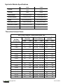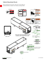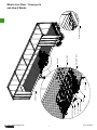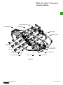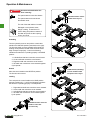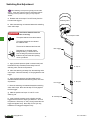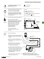
1
Owner's Manual:
i-4000 and i-6000 SERIES
TM
LIVE FLOOR
CONVEYING SYSTEMS
One-Way (i-4100/i-6100) and Two-Way (i-4200/i-6200)
West Coast USA
6605 Ammunition Road
P.O. Box 505
Tillamook, OR 97141
Ph. 800-542-5526
Ph. 503-842-8886
Fax: 503-842-4866
Central USA
8276 Hwy. 16 North
Poteet, TX 78065
Ph. 877-425-5261
Ph. 830-742-8441
Fax: 830-742-8682
Web: www.hallcoind.com Email: [email protected]
East Coast USA
480 Millrun Rd.
Salisbury, NC 28144
Ph. 800-230-0190
Ph. 704-636-4122
Fax: 704-636-1644
Doc # 99-5846-A
Hydraulic Module Specifications
i-4000
i-6000
One Way
i-4100
i-6100
Two Way
i-4200
i-6200
1.5 inch [38.1 mm]
1.5 inch [38.1 mm]
Shaft Diameter
Cylinder Diameter
Stroke
3 inches [76.2 mm]
3.5 inches [88.9 mm]
9-1/4 inches [235 mm]
9-1/4 inches [235 mm]
Maximum Pressure
3000 psi [207 Bar]
3000 psi [207 Bar]
Maximum Flow Rate
30 gal/min [114 l/min]
30 gal/min [114 l/min]
35 Ton [31 Tonne]
45 Ton [40 Tonne]
Load Capacity
Theoretical Unload Times
45 ft. [14 m] Container. Actual unload times vary.
Cycle Time
(seconds)
Convey Speed
(ft./min. [m/min.])
Unloading Time
(minutes)
Oil Flow
(GPM [LPM])
i-4000
i-6000
i-4000
i-6000
i-4000
i-6000
15 [57]
12.5
17.7
3.9 [1.19]
2.8 [ 0.84]
11.6
16.3
16 [61]
11.7
16.6
4.1 [1.26]
2.9 [0.90]
10.8
15.3
17 [64]
11.1
15.6
4.4 [1.34]
3.1 [0.95]
10.2
14.4
18 [68]
10.4
14.7
4.7 [1.42]
3.3 [1.01]
9.6
13.6
19 [72]
9.9
14.0
4.9 [1.50]
3.5 [1.06]
9.1
12.9
20 [76]
9.4
13.3
5.2 [1.58]
3.7 [1.12]
8.7
12.3
21 [79]
9.0
12.6
5.4 [1.66]
3.9 [1.18]
8.3
11.7
22 [83]
8.5
12.1
5.7 [1.74]
4.0 [1.23]
7.9
11.1
23 [87]
8.2
11.5
6.0 [1.82]
4.2 [1.29]
7.5
10.7
24 [91]
7.8
11.1
6.2 [1.90]
4.4 [1.34]
7.2
10.2
25 [95]
7.5
10.6
6.5 [1.98]
4.6 [1.40]
6.9
9.8
26 [98]
7.2
10.2
6.7 [2.06]
4.8 [1.45]
6.7
9.4
27 [102]
7.0
9.8
7.0 [2.13]
5.0 [1.51]
6.4
9.1
28 [106]
6.7
9.5
7.3 [2.21]
5.1 [1.57]
6.2
8.8
29 [110]
6.5
9.2
7.5 [2.29]
5.3 [1.62]
6.0
8.5
30 [114]
6.3
8.8
7.8 [2.37]
5.5 [1.68]
5.8
8.2
Copyright 2013
Doc # 99-5846-A
CONTENTS
SAFETY
3
What a Live Floor Conveyor Is
and How it Works
TM
6
Operation & Maintenance
9
Troubleshooting
11
Switch Rod Adjustment
13
Hydraulic Requirements
14
Parts Lists
15
Repair Guide
21
Warranty
29
30
31
32
33
35
Copyright 2013
2
Doc # 99-5846-A
Safety & Operational Decals
Before operating the LIVE FLOOR system make sure the safety and
operational decals are installed on the container per the figure below.
TM
# 99-4806
# 99-4400
# 99-4807
DANGER
!
When the floor is moving
with a load, the load and the
vehicle can crush and pin.
While moving a load
1
Keep Away From:
The Rear End of the Trailer
Under the Trailer
2
Qty 2
3
Inside the Trailer
In Front of the Tractor
Stay near the floor or PTO
controls while conveying.
Hallco Industries #99-4806
Qty 2
Qty 2
# 99-4808
4
Qty 3
1
!
KE
DA
EP
!
HA
NG
ND
DA
ER
S
AW
AY
RD
ER
À
L’ÉLES
CA MA
RT INS
GA
NG
ER
# 99-4399
6
7
AV
IS
RAP
PEL
LES EZ-V
SER BOU
OUS
PEU DESRÉS LON
VEN BOUEN S DE
GAR
TOUDE
T
ENDLON
PONDER
S T TEM T
OMM
DÉV
PS.
AGE ISSÉ
IM
!
PO
RT
AN
R
T
LE S
PON
T.
WAR
Movi
ng
Keep parts
can
out
Lock
durin crush
out
g
and
Disen - powe opera
cut.
tion.
gage
r.
PTO
befor
e enter
NING
5
4
ing.
!
AVE
RTISSE
Les
écrapièc
Se ser es
fonc
mob
tenir et coup
iles
éloig er.
Verr tionn
peuv
Déseouill emené
ent
d’en
age nt.lors
ngag
du
trer.
er alim
enta
le
PTO
tion.
avan
t
MEN
T
3
!
rea
r
AV
Res
ER
de ter loin TISSE
la
du rem de MENT
dév orq l’ar
ers ue rièr
em lors e
ent
Qty 1
2
WA
RN
Sta
y
wh clear ING
ile
unl of trai
oad ler
!
ing
AV
ER
TIS
# 99-4398
Do
not TO
conve
enter PRE
Durin yor
VEN
is the
disch
in trailer
g
opera opera
T
POS
Operaarges
or
tion, tion.
, or
go
SIBL
tor
under
Do
thedo
not
not must
perfor
E
trailer
trailer INJU
move
leave remai
opera
Alwayming
body RY
throug
floor n
movin
at
maint
tes.
s disen
while OR
systemthe
h
g
contro
or
DEA
the gageenanc
the
stand
trailer
e opera
Hallco TH
the or servic ls while
in
ting
.
the
POU
PTO
Live
while the
area
when e.
R
Floor
load
where
entrer PRÉ
vehicl
TM
the
disch
Lors yeur
dans VEN
floor
the
e is
chargdu
Hallco
arges
load
IR
foncti
system unatte
la
Liveremor LES
L’opé e est
.
nded
onnem Floor
déver
is
que
BLE
Ne rateur
not
or
MC
sée ent,
ou
pas
laissé
when
in
doit
et ne est aller SSU
use
laisse
deme où pas en
or
Toujo sans
sous RES
opéra
la
r le
when
se
ou
urer remor
la
urs survesystèm
prome tion.
lorsqu
remorOU
que
désen illance aux
LA
e la
e de contrô estner
que
MOR
gager
en ou
ou planc
remor
lorsqu
les
se
foncti
lors
T
le
tenir
lorsqu
que
PTO
deher
on. dans e le
est lorsqula foncti
e la
maint
dépla
la
onner charg
zone
e le
enanc
cée.
lorsqu e est
systèm
où
e du
la
e le déver
e de véhicu
véhicu sée.
planc
le.
le
her
est
n’est
SE
ME
NT
Ne
pas
convo
5
4
!
WARNING
Moving parts can crush and cut.
Keep out during operation.
Lockout - power.
Disengage PTO before entering.
!
pas
utilisé
AVERTISSEMENT
Les pièces mobiles peuvent
écraser et couper.
Se tenir éloigné lors du
fonctionnement.
Verrouillage - alimentation.
Désengager le PTO avant
d’entrer.
6
Rear decals should be applied so they are
completely visible with the doors open.
Trailer front
Qty 1
# 99-4401
7
Qty 1
# 99-4809
1
!
3
2
SE
ME
NT
ING r
rea
RN
WA trailer
!
of
ar ing
y cle oad
NT
Sta unl
ile
SEME
wh
TIS rière
ER
AV de l’ar
lors
!
loin ue
ter orq
Res rem ement
la ers
de
dév
du
4
NING
!
WAR
can
and
crush
tion.
KE
!
ER
NG AY
DA S AW
ND
HA
ER
NGMAINS
DALESRT
AVE
CA
T
MEN
ent
peuv
iles
mober. du
escoup lors
tion.
né
piècet
nt. enta t
Les ser éloig
eme alim avan
écra
tenir
age PTO
Se tionn
foncouill er le
Verr ngag
Désetrer.
d’en
!
cut.
parts g opera
ng
ing.
durin
Movi
r.
out
e enter
Keep - powe befor
out
PTO
Lock
gage
Disen
TM
TH
Floor
DEALive
OR
load
RY the Hallco the
INJUwhile
where
E
area
.
SIBL body
the
when
in
arges or
POS trailer
T
stand
disch nded
under
or
h
VEN go
when
load
unatte
or
the
PRE or
throug
e is
use
tion.
in
tes. while
TO trailer
move
ls
vehicl
the
T
not
opera not opera
is
in
enter
do
contro while
MOR
is
trailer the
notyor
ting
system
tion,
LA e le
e.
the n at
Do
la
floor
OU lorsqu
opera
, or
conveg opera
où
servicthe
remai
arges
RES que
e or
zone
system
Durin
la
must
when
disch tor
SSU remor dans
floorenancPTO
sée.
la
BLE
Opera leavemaint the
déver est
sous
tion. se tenir
le
notming gage.
on. e est
LES
Do
opéra ou
IR ou aller
trailer
ner foncti charg le véhicu utilisé
en
perfors disen
en
e le.
the
VEN que
pas
MC est
g
e la
prome
est
Alway
PRÉla remor
seque
lorsqu
véhicu n’est
movin
Floor
lorsqu
R
du
pas
her
les
onnere
POU dansLive nela remor
enancde planc
ent,
contrô foncti
où
Hallco
entrer
e
et
hermaint
aux
pasyeur
onnem
la
sée
urer planc
Ne
systèm
de
déverdeme e delors
convo foncti
e le
duest
ou
e
doit
cée.
lorsqu
Lors
systèm
chargrateur r le illance PTO
dépla
le est
surve
L’opé laisse
que
gager
passans
Ne
remor
désen
laisséurs e la
AV
ER
TIS
Logo sticker should be
placed on rear door.
8
EP
ER
RD L’É
GA À
RTISSE
# 99-4813
Toujo
lorsqu
ou
9
Qty 1
Extra Logo Sticker
Qty 1
Copyright 2013
3
Doc # 99-5846-A
AVOID the product hazards shown on this page
DURING FLOOR MOVEMENT or personal injury
or death WILL occur.
!
DANGER
Product Hazards
TM
The discharge end of a
Live Floor conveyor and
in front of the vehicle
during operation when a
load is at the discharge end.
The space between the front
wall and an object or pile
on the floor that is near
the front wall.
Damaged or cut hydraulic hoses,
fittings or tubing. A small hole
in a hose or fitting will produce a
stream of fluid that can pierce the
skin injecting oil into your blood.
The space between cross-drive
beams.
The space between shoe ends
and the subdeck ends.
The area between clamps.
The area between the triggers and
the switching rod bumpers.
The area between the triggers and
the surrounding framework.
The bolt hole in the hold down
blocks.
The end of the slats and the
front wall.
AVOID the product hazards listed on this page
while hydraulic FLUID IS FLOWING TO the floor
system or personal injury or death MAY occur.
Copyright 2013
4
Doc # 99-5846-A
NOTICE
Take the following actions to prevent property
damage:
Make sure the system pressure never
exceeds the maximum pressure specified
in this manual.
For warranty purposes, get approval from
the Original Equipment Manufacturer prior to
welding or drilling on their product
(trailer, etc.).
Monitor the oil temperature during
operation to prevent it from exceeding
180 deg. F (82 deg. C).
Cover the shaft chrome before welding or
painting nearby. Remove covering before
operating the system.
Operate the Live Floor in the unload mode
only when the discharge doors are open.
Support hoses and protect them against
abrasion from contact between other
components.
Install a filter in the return line as close to
the tank as possible before operating the
floor system.
Watch the space between the front wall
and the load while operating the Live Floor
in the load mode. Stop the conveyor if it is
in the load mode and the load is touching
the front wall.
Install a high pressure filter in the pressure
line between the pump and the conveyor
system before operation.
Deck bolts must be re-torqued after the first
5-10 loads! Failure to do this will result in
damage to the slats and drive unit!!!
Copyright 2013
5
Doc # 99-5846-A
What a Live Floor Conveyor Is
and How it Works
TM
A Live Floor conveyor is made of multiple slats or boards
that are as long as the conveyor. The slats are arranged
side by side and all at the same level so they cover the
entire width of the floor. They don't move up and down or
side to side, only back and forth.
Entire trailer loads are unloaded at once by: Conveying all
of the slats together in one direction for a stroke; Keeping two
thirds of the slats stationary and retracting one third at a time
under the load to their original position; Then conveying all of
the slats together again.
The slats are divided into three groups and each group is
driven by a hydraulic cylinder. There are very few moving
parts.
First Group Retract
Second Group Retract
Third Group Retract
All Groups Convey Together
Copyright 2013
6
Doc # 99-5846-A
Copyright 2013
7
Bearing
Drive Unit Frame
Control Valve
Cross Drive
Cross Drive Shoe
Slope Sheet
Sub-deck
Deck Bolt
Deck Slat
Un
it
Hydraulic Module
ve
Dri
Hold Down Block
What a Live Floor Conveyor Is
and How it Works
TM
Doc # 99-5846-A
What a Live Floor Conveyor Is
and How it Works
TM
Control (On/Off) Valve
Front Cylinder Set
Front Trigger
Rear Trigger
Switching Valve
Front
Cross-Drive
"T" - Tank/Return
Center
Cross-Drive
"P" - Pressure/Supply
Rear
Cross-Drive
Switching Rod Stop
Rear Cylinder Set
Poppet Valve
Switching Rod
Drive Unit
Copyright 2013
8
Doc # 99-5846-A
Operation & Maintenance
!
DANGER Avoid these hazards when the
floor is moving:
The space between cross-drive beams.
UNLOAD Position: Pull the
handle all the way out.
The space between shoe ends and
the subdeck ends.
The end of the slats and the front wall.
Damaged or cut hydraulic hoses,
fittings or tubing. A small hole in a
hose or fitting will produce a stream of
fluid that can pierce the skin injecting
oil into your blood.
Unloading
Turn the hydraulic power on and pull the control valve
handle to the UNLOAD position (see sketch to the right).
The floor may begin to move erratically at first while it is
clearing out air pockets, but after a few seconds should
begin to sequence properly. Look for the following
indications that the floor is operating properly in UNLOAD
position:
1. Left side/front shaft and cross-drive move forward.
2. Center shaft and cross-drive move forward.
3. Right/rear shaft and cross-drive move forward.
4. All shafts and cross-drives move rearward together.
Cycle repeats...
Neutral
LOAD Position (Two-Way):
Turn the handle forward
and push it all the way in.
Move the control handle to the NEUTRAL position:
The floor should not move.
Loading
Turn and push the control handle to the LOAD position
(two-way models only). Look for the following indications
that the floor is operating properly in LOAD position:
1. Right side/rear shaft and cross-drive move rearward.
2. Center shaft and cross-drive move rearward.
3. Left side/front shaft and cross-drive move rearward.
4. All shafts and cross-drives move forward together.
Cycle repeats...
NEUTRAL Position: Push the
handle in until it hits
the valve body
Copyright 2013
9
Doc # 99-5846-A
Operation & Maintenance
Inspect your floor regularly in order to monitor wear of your
floor and to prevent further damage, if damage has already
occurred. The following is a list of critical areas to inspect:
Socket, Flat
Head Screw
Deck Bolts:
The deck bolts connecting the deck slats to the cross
drives must be kept tight at all times! Loose deck bolts will
damage your deck and cross-drive shoes. The torque of
the deck bolts must be checked on a regular basis and at
least after the first 5 to 10 loads. Re-torque from underneath
to one of the following torques:
3/8" [9.5 mm] diameter bolts torque to 35 ft-lbs [47 N-m].
1/2" [13 mm] diameter bolts torque to 55 ft-lbs [75 N-m].
Cross-Drive
Shoe
Locknut
Deck Slat
Bearing
Seal (if applicable)
Decking:
Inspect for wear or damage.
View Looking Forward
Bearings:
Plumbing
Inspect for wear or damage.
Anchor Bolts
Tie Bolts
Hydraulic Plumbing:
Inspect the hydraulic system for leaks and abrasion.
Maintain reservoir minimum/maximum levels.
Clamp Bolts
Floor Structure:
Inspect the floor structure including hydraulic module
mount and framework, hydraulic shafts, shaft-to-cross drive
connections, cross drives, and sub-deck for damage and
wear.
Hydraulic
Module
Hydraulic Module:
Inspect the hydraulic module for leaks, loose mounting
bolts, loose manifold bolts, worn wipers and seals, and
pitted/worn/damaged shafts.
Floor Structure
Check the torque of the tie bolts, anchor bolts and clamp
bolts regularly and at least after the first 5-10 loads.
Slope Sheet Support Bracket
(Several Over the Width)
Tie Bolts Torque: 150 ft-lbs [203 N-m]
Anchor Bolts Torque: 150 ft-lbs [203 N-m]
Clamp Bolts Torque: 120 ft-lbs [163 N-m]
Slope Sheet
FWD
Sloped Sheet & Wiper:
Make sure the sloped sheet is in good condition and that
the wiper attached to the sloped sheet is keeping the gap
between the forward wall and the end of the decking clear
of material which could cause the floor to bind.
Wiper
Deck Slat
Sub-deck
Copyright 2013
10
Forward Wall
Doc # 99-5846-A
Troubleshooting
In the "Trouble" column below, find the description that
best matches the trouble you are experiencing with the
TM
Live Floor system. The Item # columns refer to the
pictures on the following page. A dark cell means that
the item is a suspected cause of the trouble described
in that row.
Switching Valve
Hose Routing (Plumbing)
8
Return Filter
7
Pressure Filter
6
Slats
Cross-Drive Beams
5
Slat ends at front wall.
Pistons/Cylinders
4
Rear Poppet #2
Control Valve
3
Rear Poppet #1
Switching Rod Bumpers
2
Front Poppet #2
Quick Connect Couplers
1
Front Poppet #1
Tank/Reservoir
Item #
Pressure Relief Valve
Trouble
Hydraulic Pump
Check the performance of each suspected component.
Verify that it meets the minimum requirements listed for
it in this manual. Check it for visible damage and/or
interference from other parts.
Drive Shoes and Sub-deck
If the suspect is a hydraulic part, measure its temperature
using an infrared thermometer or similar device while the
system is running to see if it is warmer than the other
hydraulic parts. A hydraulic component that is damaged
and bypassing oil will heat up a lot faster than the other
hydraulic parts in the system.
9 10 11 12 13 14 15 16 17 18 19
The slats won't move and the floor is loaded.
I don't want to use a shovel!
The slats move much slower than normal when
the floor is loaded. The speed looks fine when
there is no load.
The slats move seperately when they should travel
together. *
When the slats should be retracting separately, the
first cross-drive retracts, the second retracts and
the third tries to move and can't or moves very
slowly. Everything works fine when the control
valve is switched to move the load in the opposite
direction.
When the slats should be retracting separately,
the first cross-drive retracts, then the second
cross-drive tries to move and can't or moves
very slowly. Everything works fine when the
control valve is switched to move the load in the
opposite direction.
The hydraulic fluid is overheating within 15 minutes
of operation.
The slats reach their end of stroke and nothing
happens. When I shut the power to the system off
and turn it back on, the floor may cycle or move
once but it always gets stuck at one end even
though the pump sounds like it is pumping fluid at
the maximum pressure.
The slats move together all the time. It doesn't
make a difference if I push the control valve handle
all the way in or pull it all the way out.
* The load on the floor works to keep the slats all moving together. If there is no load on the floor it doesn't take much
extra friction on one cross-drive to keep it from moving with the rest. Most of the time this trouble is fixed by loading the floor.
Copyright 2013
11
Doc # 99-5846-A
Troubleshooting Pictures
1.
2.
3.
4.
5.
6.
7.
8.
9.
10.
Hydraulic Pump.
Pressure Relief Valve.
Tank/Reservoir.
Quick Connect Couplers.
Switching Rod Bumpers.
Control Valve.
Pistons/Cylinders.
Cross-Drive Beams.
Shoes and Sub-deck.
Front Poppet #1.
11.
12.
13.
14.
15.
16.
17.
18.
19.
Front Poppet #2.
Rear Poppet #1.
Rear Poppet #2.
Slat ends at front wall.
Slats.
Pressure Filter.
Return Filter.
Hose Routing (Plumbing).
Switching Valve
Hydraulic Power Supply
15
17
4
3
14
View From Underneath
16
1
2
18
9
8
10
6
11
9
5
12
13
19
7
Copyright 2013
12
Doc # 99-5846-A
Switching Rod Adjustment
TIP The switching rod stops are typically pre-set at the
factory. If the drive unit has been pre-assembled and the
switching rod stop collars are tight, you may skip this
section.
a. Release and move stops “A” and “B” away from the
front and rear triggers.
Switching Valve
b. Move the switching rod rearward toward the switching
valve until it stops.
!
DANGER Avoid these hazards when the
floor is moving:
5/8" Spacer Collar
The space between cross-drive beams.
The space between shoe ends and
the subdeck ends.
The end of the slats and the front wall.
Rear Trigger
Damaged or cut hydraulic hoses,
fittings or tubing. A small hole in a
hose or fitting will produce a stream of
fluid that can pierce the skin injecting
oil into your blood.
c. Apply hydraulic pressure (load or unload mode) until
the shafts are fully extended forward away from the
switching valve, then shut off pressure.
a. Stop "A"
d. Move the switching rod away from the switching valve
until it stops. Move and set stop “A” firmly against the rear
trigger.
e. Apply hydraulic pressure until the shafts are fully
retracted rearward towards the switching valve, then shut
off pressure.
Front Trigger
a. Stop "B"
f. Move the switching rod rearward toward the switching
valve until it stops. Move and set stop “B” firmly against
the front trigger.
g. Mark the positions of stops “A” and “B” on the
switching rod.
b. Switching Rod
h. Apply hydraulic pressure to the cylinders until the
triggers are free from the stops by at least 3/8”. Shut off
the pressure. Move stop “A” 3/8” [10 mm] toward the rear
trigger and tighten firmly. Move stop “B” 3/8” [10 mm]
toward the front trigger and tighten firmly.
Copyright 2013
13
Doc # 99-5846-A
Hydraulic System Requirements
Hydraulic
Fluid:
Anti-Wear (AW). Viscosity of ISO 46 or 68
Petroleum OR Mineral base.
Moisture content, H2O < 1%
< 180°F [82°C]
Fluid Temperature:
Pump must be a Gear, Vane or Piston type
that will pump no more than 30 gpm
[114 Lpm] at a full 3000 psi [207 Bar].
Summary:
Flow < 30 gpm [114 Lpm]
Pump must be matched to its power source.
Drive it directly or through a PTO. Consult
a hydraulic expert to determine the required
motor/engine power.
Pump:
Use a reservoir that has all of these features:
Tank/
Reservoir:
30 gal. [114] minimum capacity.
Inlet diameter greater than 1.25 in [30 mm].
Outlet diameter greater than 2 in [50mm].
Turbulence reducer on Return inlet.
Pump supply outlet near the bottom.
Whirlpool prevention on the outlet.
Filler cap with breather and filter.
Visible fluid level gage.
Visible thermometer.
Location and specification
information is shown in the sketch
to the right.
Hydraulic
Supply
Circuit
Pressure > 3000 psi [207 bar]
Power Source > Enough for the Flow and Pressure
Speed: Motor or PTO
> 6 in.
[150 mm]
Pump
Breather fill cap
with filter
High
Thermometer:
-15 to 300°F
[-26 to 150°C]
30 Gal. [114 L]
Low
Return
Antiwhirlpl
Baffles
> 2 in.
[50 mm]
To Pump
1 - 2 in.
[25 - 50 mm]
> 1.25 in.
[30 mm]
Use all of these features.
(Optional) 75 micron Pressure Filter rated
to handle the maximum system pressure
and flow.
i-4000/
i-6000
Module
Hose
Hose
Quick Connects that are matched and
rated for the maximum system pressure
and flow rate.
1 in. [25 mm]
Hydraulic Pressure Line
Tube
Tube
1-1/4 in. [32 mm]
Hydraulic Return Line
Pressure Relief Valve set at 3000 psi
[207 Bar] and rated to handle at least
the maximum pump output flow.
T
25 micron Return Filter rated to handle
more than the maximum pump flow. Place
it as close to the tank as possible. Make the
hydraulic line between the filter and the
tank at least 1-1/2" [38 mm] diameter to
prevent filter failure.
P
Tank
Pump
Hallco recommends consulting a hydraulic
specialist to design the hydraulic supply system.
Visible Pressure Gage. 0 to 5000 psi
[0 to 350 bar]. Glycerin filled.
Copyright 2013
Sight
level
gage
14
Doc # 99-5846-A
Copyright 2013
15
Hex Socket O-Ring Plug, SAE-12
# 85-3794
Hose, 3/4" x 72" Long, 3/4" Male Pipe Ends
# 86-2698
Hex Socket O-Ring Plug, SAE-12
# 85-3794
Fitting, 3/4" Adj. Male O-Ring x 3/4" Female Pipe Swivel 90_
# 85-3953
Hose, 3/4" x ___ Long, 3/4" Male Pipe Ends
# Variable
Hose, 3/4" x 90" Long, 3/4" Male Pipe Ends
# 86-4292
Hose, 3/4" x ___ Long, 3/4" Male Pipe Ends
# Variable
Fitting, 3/4" Male O-Ring x 3/4" Female Pipe Swivel
# 85-3952
One-Way Control Valve (Unload/Neutral)
# 56-5472
3/4" Hex Head O-Ring Plug
# 85-3792
Fitting, 3/4" Male O-Ring x 3/4" Female Pipe Swivel
# 85-3952
Note: These hose ends may be swapped.
Fitting, 3/4" Adj. Male O-Ring x 3/4" Female Pipe Swivel 45_
# 85-3774
Fitting, 3/4" Adj. Male O-Ring x 3/4" Female Pipe Swivel 45 _
# 85-3774
Parts Lists - Plumbing One-Way
Doc # 99-5846-A
Copyright 2013
16
Fitting, 3/4" Male Pipe x 3/4" Female Pipe Swivel 90_
# 85-2662
Hose, 3/4" x 72" Long, 3/4" Male Pipe Ends
# 86-2698
Fitting, 3/4" Adj. Male O-Ring x 3/4" Female Pipe 90_
# 85-3948
Serial Number and Model Number
are stamped into this plate.
Fitting, 3/4" Adj. Male O-Ring x 3/4" Female Pipe Swivel 45_
# 85-3774
Fitting, 3/4" Adj. Male O-Ring x 3/4" Female Pipe Swivel 90_
# 85-3953
Hose, 3/4" x ___ Long, 3/4" Male Pipe Ends
# Variable
Hose, 3/4" x 90" Long, 3/4" Male Pipe Ends
# 86-4292
Hose, 3/4" x ___ Long, 3/4" Male Pipe Ends
# Variable
Hose, 3/4" x ___ Long, 3/4" Male Pipe Ends
# Variable
Two-Way Control Valve (Unload/Neutral/Load)
# 56-3632
Fitting, 3/4" Male O-Ring x 3/4" Female Pipe Swivel
# 85-3952
Hose, 3/4" x ___ Long, 3/4" Male Pipe Ends
# Variable
Fitting, 3/4" Male O-Ring x 3/4" Female Pipe Swivel
# 85-3952
Note: These hose ends may be swapped.
Fitting, 3/4" Adj. Male O-Ring x 3/4" Female Pipe Swivel 45_
# 85-3774
Parts Lists - Plumbing Two-Way
Doc # 99-5846-A
Copyright 2013
17
Clamp Spacer
# 51-133
5/8" NC Nut, Nylon Lock
# 81-2618
Switching Rod Stop Assy:
Collar # 51-2799
Bumper # 38-2845
Washer # 81-4497
Switching Rod - P/F Style
# 51-2802
Center Frame Style
Switching Rod
Switching Valve
# 56-3964
Switching Rod - C/F Style
# 51-2801
5/16" NC Nut
# 81-2606
Washer
# 81-4497
Cap Screw 3/8" NC x 5"
# 81-2539
Torque: 30 ft-lbs [41 N-m]
3/8" Lock Washer
# 81-2650
SW VLV Stop Assy - Short
# 51-2807
O-Ring Set
# 50-2847
Rear Clamp
# 51-4689
Cross Drives
The hydraulic module
model and Serial numbers are
required for proper ID.
5/8" Spacer Collar
# 51-2800
Switching Rod Adapter
# 51-3969
Cap Screw 5/8" NC x 2.1/2"
# 81-2583
Torque: 120 ft-lbs [163 N-m]
3/4" NC Nut,
Nylon Lock
# 81-2619
Torque: 150 ft-lbs
[203 N-m]
Clamp Tie Plate
#51-4024
Front Clamp
# 51-4690
Perimeter Frame Style
Switching Rod
Hydraulic Module W/
Switching Valve
Center Frame
# 51-3048
Alternate Configuration - Block Shafts
Cap Screw 5/8" NC x 3.3/4"
# 81-2588, Torque:
120 ft-lbs [163 N-m]
Shear Plate
(If Requested)
OR
Perimeter Frame
The hydraulic module
model and Serial numbers are
required for proper ID.
Parts Lists - Drive Unit
Doc # 99-5846-A
Copyright 2013
18
Front Base Manifold
i-4k: #54-5653
i-6k: #54-5565
*O-Ring
Head Manifold
i-4k: #54-5651
i-6k: #54-5552
Shaft, Left/Right
#55-4606
Collar Shafts
i-4k: Standard
i-6k: N/A
Shaft, Center
#55-4607
Shaft, Left/Right
#55-4606
Rear Base Manifold
i-4k: #54-5652
i-6k: #54-5553
Tie Bolt
#58-3071
Poppet Valve
i-4k: #56-5654
i-6k: #56-5551
Head Manifold
i-4k: #54-5651
i-6k: #54-5552
Poppet Cap
#85-3471
* Indicates Contents of Seal Kit
i-4k: #50-5744
i-6k: #50-5564
*O-Ring, Pair, Size 2-214
#50-2847
*O-Ring, Size 2-116
Transfer Tube
#51-2819
Barrel
i-4k: #53-5655
i-6k: #53-5554
Anchor Bolt
#58-3072
3/4" NC Nut, Nylon Lock
#81-2619
Torque: 150 ft-lbs [203 N-m]
Poppet Spring
#56-2714
*Piston Seal
Piston
i-4k: #57-2823
i-6k: #57-3024
Piston Nut
#81-3223
Torque: 300 ft-lbs [407 N-m]
*Parbak
*Shaft Wear Ring
*Shaft Seal
*Shaft Wiper
Note: Poppet valves and springs
are not installed in the front head
manifold of a one-way (i-4100, i-6100).
Block Shafts
i-6k: Standard, i-4k: Optional
(Fasteners not included.)
Block Shaft, Left
#55-2722
Block Shaft, Center
#55-2723
Block Shaft, Right
#55-2724
NOTE: All parts listed here are common to both the
i-4000 and the i-6000 unless marked with i-4k (i-4000)
or i-6k (i-6000). The serial number and model number
are located on a stainless steel plate mounted on the
underside of the Rear Base Manifold. See page 16.
Parts Lists - Hydraulic Module
Doc # 99-5846-A
Parts Lists - Switching Valve
*O-Ring Pair, Size 2-214
# 50-2847
Rear End Cap
Valve Body
(Qty 5)
*O-Ring, Size 2-117
Pilot Rod
(Qty 2)
*O-Ring, Size 2-136
(Qty 4)
Cap Screw 3/8" NC x 2.1/2"
# 81-2529
Valve Spool
*Indicates Contents of Switching Valve Seal Kit
# 50-2709
Forward End Cap
1/4" NPT Plug
# 85-3489
(Qty 2)
*O-Ring, Size 2-210
(Qty 2)
*Shaft Wiper
Complete Assembly: P/N 56-3964
Note: The switching valve is only sold as a complete assembly.
Individual components are not sold separately.
Copyright 2013
19
Doc # 99-5846-A
Parts Lists - Control Valve
Retaining Ring
# 81-3031
Valve Spool
(Qty 2) 3/4" Plug, O-Ring
85-3792
(Qty 2) Fitting,
3/4" Male O-Ring x 3/4" Female Pipe Swivel
# 85-3952
Valve Body
Control Valve Spacer Collar
# 56-5473
Valve Handle
# 56-3943
3/8" Lock Washer
# 81-2650
O-Ring Pair, Size 2-214
# 50-2847
Hex Head Cap Screw, 3/8"NF x 3/4"
# 81-3255
One-Way Control Valve
Retaining Ring
# 81-3031
(Qty 4) Fitting,
3/4" Male O-Ring x 3/4" Female Pipe Swivel
# 85-3952
Valve Spool
Valve Body
Valve Handle
# 56-3943
3/8" Lock Washer
# 81-2650
Complete Assembly:
One-Way: P/N 56-5472
Two-Way: P/N 56-3632
Note: The control valve is only
sold as a complete assembly.
Individual components are not
sold separately.
Copyright 2013
O-Ring Pair, Size 2-214
# 50-2847
Hex Head Cap Screw, 3/8"NF x 3/4"
# 81-3255
Two-Way Control Valve
20
Doc # 99-5846-A
Repair Guide - Hydraulic Module
Recommended Tools for Overhaul & Repairs
Part Number
93-4333
93-5500
56-3712
86-2972
93-4311
93-4708
Description
Head Manifold Installation Tool
Hydraulic Module Rebuild Fixture, i-Series
Poppet Seating Tool, i-Series
Pressure Gauge, 0-5000 PSI
Rod Seal Insertion Tool
3/4" Tie Bolt Installation Tool
Comment
Included in tool kit, 93-4356
For bench-top overhauls
Included in tool kit, 93-4356
Included in tool kit, 93-4356
Included in tool kit, 93-4356
For quick-driving the tie bolts
Hydraulic Module Overhaul
If the hydraulic module is accessible from below, it may be
overhauled in-place. An advantage of doing this is that the
shafts are kept from rotating by the cross drive clamps.
This is useful since the piston nuts must be tightened with
300 ft-lbs [407 N-m] of torque. Some other advantages are
that no heavy lifting is required and the shafts are always
kept in proper alignment with the cross-drives.
Depending on shop equipment available and the extent of
the overhaul, it may be more convenient to remove the
entire hydraulic module. An advantage of this is that the
majority of the work would be done in a comfortable place
away from the dirty underside of the conveyor.
Hydraulic modules may be shipped to Hallco for overhaul.
Hallco recommends keeping the switching valve assembled
in order to allow Hallco to fully test the overhauled module.
The following pages illustrate the assembly of a hydraulic
module.
Copyright 2013
21
Doc # 99-5846-A
Repair Guide - Hydraulic Module Overhaul
Slip the two part piston seals into the groove on each
piston. The black base goes on first.
Apply oil to the piston seal before inserting into the barrel.
Put the bevel side of the piston into the barrel first so that
it is toward the head manifold when the barrel is placed
over the shaft and onto the head.
Use a hydraulic press or other tool to push the piston
into the barrel/cyclinder. The flat surface of the piston
should be around 1/2 inch [13mm] inside the barrel to
make space for the o-ring boss on the base manifold.
Copyright 2013
22
Doc # 99-5846-A
Repair Guide - Hydraulic Module Overhaul
Before installing any seal be sure to inspect the seal
and sealing surface/groove and remove any debris
or rough surface.
Stretch a parabolic backup ring into each o-ring boss
groove on the head and base manifolds. The cupped
surface should face toward the inside of the barrel.
O-Ring
Backup
Then stretch an o-ring into the grooves so that the o-ring
will be furthest toward the inside of the barrel. Be sure
that the o-ring is sitting down in the groove all the way
and not resting on the backup ring.
Wipe oil onto the o-rings. If they are not oiled the o-rings
could be damaged when the barrel is slid over the o-ring
boss.
Wipe oil onto the transfer tube o-rings and then insert
them into the transfer tube grooves in the head and base
manifolds.
Use the poppet seat tool and a hammer to form the seat
for the poppet to seal against.
Fold the wear rings and insert them into the wide groove
in the shaft holes.
Use the rod seal insertion tool to fold the shaft seal as
shown. Insert the seal into the next groove up from the
wear ring in the shaft holes. Orient the seal so that the
wiper lip is toward the barrels.
Copyright 2013
23
Doc # 99-5846-A
Repair Guide - Hydraulic Module Overhaul
Use the rod seal insertion tool again to fold and install
the shaft wiper seals. Orient the seal so that the wiper lip
is directed away from the barrels.
Insert the poppet, spring and cap into the poppet ports in
the head manifolds as shown. Apply oil to the poppet cap
o-rings before inserting the caps.
Clean the portion of the shafts that will be inside the
cylinder barrels. Inspect the chrome surface for dents,
missing chrome or any other defect that would damage
the seals.
Apply oil to the shaft seals and slide the heads onto the
shafts. Orient the heads so that the centerline marks both
face in the same direction.
Use the head installation tool to draw the shafts through
the shaft seals. Slide the heads onto the shafts so that
the inside face of the heads is 11-1/4" [285 mm] from the
end of the shafts.
Take a barrel with a piston installed in one of its ends and
slide the open end without the piston over a shaft and
push it over an o-ring boss. The threaded end of the shaft
will slide into the piston hole. The end of the barrel should
seat against the bottom of the o-ring boss slot. Do this on
all of the shafts.
Thread the piston nuts on the shafts and tighten to 300
ft-lbs [407 N-m] torque against the pistons. The
assembly jig is very helpful in keeping the shafts from
turning when torquing the piston nuts!
Copyright 2013
24
Doc # 99-5846-A
Repair Guide - Hydraulic Module Overhaul
Insert the transfer tubes into the head manifolds.
Insert the tie bolts through the four holes in the center of
the bases and thread them into the heads. The tie bolt
insertion tool makes it easier to turn the tie bolts. Sink
the tie bolts into the heads as far as they will go.
Insert the base manifold o-ring bosses into the barrels
and the transfer tubes into the base. Orient the bases
so that the transfer tubes from the heads line up with the
transfer tube ports in the bases.
Tighten the tie bolt nuts but do not torque them until
installing the module into the frame.
Make sure that the transfer tube is inserted
NOTICE
into both the head and the base before tightening the tie
bolt nuts!
Insert the o-rings into the switching valve ports on the
base then insert the four switching valve bolts through the
base. Orient the switching valve so that the pressure
gage port comes out toward the opposite side from the
centerline marks on the head manifolds. Slide the
switching valve onto the bolts and tighten the bolts to 30
ft-lbs [41 N-m].
Thread the switching valve stop assembly into the spool
of the switching valve. Don't worry about torquing it yet.
Apply oil to the o-rings of each fitting before installing it.
Use the plumbing illustrations on page 14 or 15 as a
guide for the placement and orientation of each fitting.
Apply teflon tape to any non-swivel pipe thread joint.
Copyright 2013
25
Doc # 99-5846-A
Repair Guide - Hydraulic Module Overhaul
Coat the steel mounting flanges with a galvanic corrosion
inhibitor such as * ECK corrosion prevention coating.
R
Move the module into place near the cross-drives. Orient
the module so that the long base manifold is closest to
the discharge end of the conveyor and the centerline
markings on the head manifolds are facing up. Loosely
fit the anchor bolts into the module before moving it into
place.
It may be necessary to cut the bridge strap on the
perimeter frame in order to install the module. If this is
necessary insure that there is very little load on the floor
in the area over the frame. Then cut the strap near the
vertical posts. After the module has been installed and
tested, the strap that was removed must be welded back
in place with reinforcement. It must be as strong as the
original configuration.
Coat this area
with ECK or other
anti-corrosion.
Cut Strap if Necessary.
Reinforce When Replacing it.
Fit the clamps over the shafts around the collars or
blocks. Loosely thread the clamp bolts into place. Insert
the anchor bolts into the mounting frame.
Torque the cross-drive clamp bolts to the value shown in
the exploded view on page 16.
Tighten the tie and anchor bolts a little at a time following
a cross pattern as illustrated so that the manifolds remain
parallel as they are pressed towards each other. Torque
the anchor bolts and tie bolts to 150 ft-lbs [203 N-m].
7
1
4
6
5
3
2
8
Tie Bolts
Anchor Bolts
Tighten the tie and anchor bolts using a cross pattern.
Thread the switching rod through the trigger nearest the
switching valve. Slide the switching rod bumper
assemblies in place as shown here. Continue threading
the switching rod through the next trigger.
Place the 5/8" [16 mm] collar onto the switching rod end
of the pilot rod. Slide the switching rod adapter (if
working on a perimeter frame) onto the switching rod and
bolt the adapter to the end of the pilot rod. Or install a
nut and washer on the end of the switching rod and
thread it into the end of the pilot rod (if working on a
center frame). The bolt on the other end of the pilot rod
may be held to keep the rod from rotating while the
switching rod is tightened onto the pilot rod.
Hang the control valve in place insuring that the plastic
spacer plate is between the steel hanger and the
aluminum valve body. Torque the bolts to 30 ft-lbs
[41 N-m].
Spacer
Plate
Attach the hydraulic hoses using the illustrations on page
14 or 15 as a guide.
* ECK is a registered trademark of VAN NAY, LLC Corp. 389 Sundown Rd S. Elgin, IL 60177
Copyright 2013
26
Doc # 99-5846-A
Repair Guide - Switching Valve Overhaul
The switching valve can be overhauled to correct
external seal leakage only — not bypass. If any of the
major components require replacement, the entire
valve will need to be replaced.
*O-Ring Pair, Size 2-214
# 50-2847
If the switching valve is a lot hotter than the other
hydraulic components during operation then a large
amount of oil is being bypassed. Send the switching
valve to Hallco for testing or replace the valve
entirely.
(Qty 2)
*Shaft Wiper
(Qty 2)
*O-Ring, Size 2-210
Disassembling the Switching Valve
Rear End Cap
Remove the cap screws which attach the end caps
to the valve body.
(Qty 2)
*O-Ring, Size 2-136
Slide the end caps away from the valve body.
Remove the pilot rod and the spool.
(Qty 5)
*O-Ring, Size 2-117
Remove the o-rings and shaft wipers.
Inspecting the Switching Valve Components
Valve Body
Inspect the spool, pilot rod, spool bore, and pilot rod
bores for scoring and burrs.
Inspect all the remaining seal areas. The seal areas
must be smooth and free of scoring and burrs.
Inspect the fasteners and threaded holes for good thread
engagement.
Valve Spool
Reassembly of the Switching Valve
Hallco recommends replacing all the switching valve
seals when overhauling the switching valve.
Pilot Rod
Lubricate the shaft wipers and o-rings with hydraulic fluid
and install them in the end caps.
Lubricate the valve spool and pilot rod with hydraulic fluid
and insert the spool into the valve body and the pilot rod
into the spool. Center them on the valve body.
Place the o-rings which go between one of the end caps
and the body in their respective seal grooves and slide on
the end cap. Note the location of the alignment pin.
Repeat for the other end cap.
Install the cap screws which hold the forward end cap on,
snug them up, then torque them to 30 ft-lbs [41 N-m].
Use two of the same size cap screws to hold the rear end
cap snug until it is ready to be installed on the hydraulic
module.
Forward End Cap
(Qty 4)
Cap Screw 3/8" NC x 2.1/2"
# 81-2529
1/4" NPT Plug
# 85-3489
*Indicates Contents of Switching Valve Seal Kit
# 50-2709
Complete Switching Valve Assembly #56-3964
Copyright 2013
27
Doc # 99-5846-A
Repair Guide - Control Valve Overhaul
The control valve can be overhauled to correct external
leakage only. If the valve has excessive internal bypass,
it will need to be replaced entirely.
Disassembling the Control Valve
Remove the cap screw and lock washer which attach
the valve handle to the spool. Note: If the spool
turns so that the screw cannot be removed, hold the
end of the spool at the opposite end beyond the
retaining ring with locking pliers or similar. Do not
grip the area which slides in the valve body.
Remove the spacer collar (one-way only).
Remove the spool by sliding it toward the retaining
ring side. Note that the retaining ring does not have
to be removed.
Remove the two o-rings from the valve body.
Reassembling the Control Valve
Prior to reassembly inspect all components for wear and
damage. Do not reinstall defective components.
Replace the two o-rings in the valve body with new
o-rings. Lubricate the o-rings with hydraulic fluid
before installing them.
Install the retaining ring on the spool, if it was
removed.
Lubricate the spool with hydraulic fluid and insert it
into the valve body.
Attach the valve handle with the cap screw and lock
washer.
Copyright 2013
28
Doc # 99-5846-A
NOTICE
Deck bolts must be re-torqued after the first 5-10 loads!
Failure to do this will result in damage to the slats and drive unit!!!
WARRANTY
- Damage occurring during shipment of the product.
(Such claims must be presented directly to the
freight company).
- Damage to the product resulting from improper
maintenance or repair, the use or installation of
parts and or accessories not manufactured by
Company, or which are not compatible with the
system, or failure to follow product warnings and
usage instructions.
- Normal wear and tear.
- Any product for which Customer does not follow
the warranty procedures stated above.
Hallco Industries, Inc. (“Hallco” or “Company”) warrants
to the original product purchaser (“Customer”) each of
the Hallco LIVE FLOORS® or its other floor systems
manufactured and sold by it or any of its authorized
distributors, when properly assembled and installed, to
be free from defects in material and workmanship. This
warranty expressly excludes deck seal, when used.
Company’s obligation to Customer under this warranty
is limited to repairing or replacing, as herein provided,
and at its sole option, any part or parts of the system
which within twelve (12) months after delivery to
Customer shall be found, upon examination by
Company, to be defective, provided that such part or
parts shall be returned, with insurance and shipping
costs at Customer’s expense, to Company’s factory at
6605 Ammunition Road, Tillamook, Oregon 97141.
Company must be notified in writing of any claim under
this warranty within 30 days of any claimed lack of
conformity of the product.
WARRANTY LIMITATIONS. THIS WARRANTY IS
MADE EXPRESSLY IN LIEU OF ANY OTHER
WARRANTIES, EXPRESSED OR IMPLIED,
INCLUDING ANY IMPLIED WARRANTY OF
MERCHANTABILITY OR FITNESS FOR ANY
PARTICULAR PURPOSE, AND OF ANY OTHER
OBLIGATION OR LIABILITY ON THE PART OF THE
MANUFACTURER.
WARRANTY SERVICE OPTIONS. For service under
this warranty, Customer must notify Company in writing
to obtain a Returned Material Authorization Number
(RMAN). When requesting your written RMAN, specify
in writing the part in question by part number &
applicable purchase order number. Customers in
countries other than the United States should contact
Company’s authorized representative in such country,
when applicable.
In no event shall Company be liable for any loss,
inconvenience or damage, whether direct, incidental,
consequential or otherwise, except for the repair or
replacement obligation as set forth herein. Some states
or countries do not allow limitation on how long an
implied warranty lasts and some do not allow exclusions
or limitations of incidental or consequential damages, so
the above limitations or exclusions may not apply to you.
This warranty will be interpreted pursuant to the laws of
the United States and the State of Oregon.
WARRANTY EXCLUSIONS. Representatives of
Company are not authorized to modify this warranty in
any way. It is the Customer's responsibility to regularly
examine the product to determine the need for normal
service or replacement. This warranty does not cover
the following:
- Products that have been modified, altered,
neglected or poorly maintained, misused, abused
or involved in accidents or natural disasters, or
repaired other than by Company in accordance with
these warranty procedures;
HALLCO INDUSTRIES, INC. - P.O. BOX 505 - TILLAMOOK, OREGON 97141
PHONE (800) 542-5526 - FAX (503) 842-4866
Copyright 2013
29
Doc # 99-5846-A