1
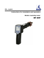
EN - english
Instructions for installation and operation
Mobile humidity meter
DP 207
Dear customers,
Thank you very much for deciding in favour of the mobile humidity measuring instrument DP 207. Please
read this installation and operation manual carefully before using your DP 207 and follow our advice. A riskless operation and a correct functioning of DP 207 are only guaranteed in case of careful observation of the
described instructions and notes.
BEKO TECHNOLOGIES GMBH
Im Taubental 7
D-41468 Neuss
Phone: +49 (0)2131 988 0
Fax: +49 (0)2131 988 900
Mail: [email protected]
Web: http://www.beko.de
2
DP 207
Table of contents
1
Safety instructions ..................................................................................................................................4
2
Field of application .................................................................................................................................6
3
Technical data ........................................................................................................................................7
4
Dimensional drawing ..............................................................................................................................8
5
Scope of delivery....................................................................................................................................9
6
Operation..............................................................................................................................................10
7
7.1
7.2
Measurements......................................................................................................................................10
Measurement with measuring chamber, connection via plug nipple ...................................................10
Measurement without measuring chamber, connection via external thread G½’’ ...............................10
8
Maintenance.........................................................................................................................................11
9
Calibration/ Adjustment ........................................................................................................................11
10
10.1
10.2
10.3
10.4
10.5
Humidity reference cells .......................................................................................................................12
Functional principle humidity reference cells .......................................................................................12
Performance features...........................................................................................................................12
Fields of application .............................................................................................................................12
Durability ..............................................................................................................................................12
Versions ...............................................................................................................................................12
11
Stabilization time ..................................................................................................................................13
12
12.1
12.2
Tables lithium chloride .........................................................................................................................13
Humidity developing .............................................................................................................................13
Dew point survey..................................................................................................................................13
13
Conformity declaration .........................................................................................................................14
DP 207
3
Safety instructions
1
Safety instructions
Please check whether this instruction corresponds with the instruments type.
Please observe all notes indicated in this instruction manual. It contains essential information
which have to be observed during installation, operation and maintenance. Therefore this instruction manual has to be read categorically by the technician as well as by the responsible
user / qualified personnel before installation, initiation and maintenance.
This instruction manual has to be available at the operation site of DP 207 at any time.
Regional respectively national regulations have to be observed in addition to this instruction
manual if necessary.
In case of any obscurities or questions with regards to this manual or to the instrument please
contact BEKO TECHNOLOGIES.
Warning !
Compressed air !
Contact with quickly or abruptly escaping compressed air or bursting plant components
may cause severe injuries or death.
Measures :
•
Do not exceed the maximum operating pressure (see type label)!
•
Only use pressure-resistant installation material!
•
Avoid persons or objects being hit by escaping compressed air!
Warning !
Supply voltage !
Contact with supply voltage carrying non-insulated parts may cause an electric shock
with injury and death.
Measures :
•
Observe all applicable regulations for electrical installations (e. g. VDE 0100)!
•
Carry out maintenance work only in disconnected state!
•
All electric works are only allowed to be carried out by authorized qualified personnel.
Warning !
Inadmissible operating parameters !
Undercutting respectively exceeding of limit values may cause danger to persons and
material and may lead to functional and operational disturbances.
Measures :
•
Do not exceed maximum operating pressure (see type label)!
•
Make sure that DP 207 is only operated within the admissible limit values indicated on the type label.
•
Careful observation of the performance data of DP 207 in connection with the application.
•
Do not exceed the admissible storage and transportation temperature.
•
Carry out maintenance and calibrations in regular intervals.
4
DP 207
Safety instructions
Further safety instructions:
•
Also the applicable national regulations and safety instructions have to be observed during installation
and operation.
•
DP 207 is not allowed to be used in explosive areas.
Additional remarks:
•
Do not overheat the instrument!
•
In case of mounting by screwing please use spanner flat (SW27)!
•
DP 207 is not allowed to be disassembled!
Attantion !
Malfunctions at DP 207
Faulty installation and insufficient maintenance may lead to malfunctions at DP 207
which may affect the measuring results and which may lead to misinterpretations.
r
Measures :
Let compressed air flow off at the sampling point before measurement in order to remove condensate and
particles. This avoids a soiling of DP 207 and the measuring chamber.
Stagnant air leads to long adjustment times.
DP 207
5
Field of application
2
Field of application
•
DP 207 is a mobile, wireless humidity measuring instrument for measurements within the admissible
operating parameters (see Technical data).
DP 207 is designed for measurements behind a compressed air dryer. In case of measurements in front
of a compressed air dryer the measuring instrument/ the sensor may be damaged.
DP 207 measures the following parameters:
Temperature
Relative humidity
Dew point up to 50 bar
Upon customer request further parameters can be programmed by BEKO TECHNOLOGIES GMBH:
ppm, g/kg, mg/m³, atmospheric dew point.
DP 207 is able to measure in the following media resp. measurable gases:
Medical gases, inert gases, non-corrosive gases, SF6...
For example DP 207 can be used in the following applications
Compressed air systems
Compressed air dryers
For functioning DP 207 requires an operating voltage (see Technical data).
DP 207 is not suitable for an application in explosive areas .
We always recommend to use a measuring chamber
Advantages:
•
•
•
•
•
•
•
•
•
6
• easy mounting and dismounting under pressure
• fast response time
Measuring chamber with internal thread G½“ and mounted plug nipple NW 7.2 for quick-lock coupling.
Use a diffusion-tight teflon cable for non-accessible sites.
DP 207
Technical data
3
Technical data
Measuring ranges
-80... 50°C td
-20... 70°C
0... 100 % RH
Upon customer request further parameters can be programmed by
BEKO TECHNOLOGIES ppmV/V, atmospheric dew point, g/m³,
mg/m³, g/kg, or °F
Pressure range
Mounting without measuring chamber: -1 to 50 bar (standard)
Mounting with measuring chamber: -1 to 16 bar
Connection measuring chamber
Internal thread G½“ / G¼“
Plug nipple NW 7,2; G¼“ external, for quick-lock coupling.
Purge air requirement
16 l/min when using the measuring chamber (for 7 bar)
Display
Single-line, resolution 0.1
Dew point (°C td)
Relative humidity (% RH)
Temperature (°C or °F), according to factory setting
Maximum 3 parameters can be chosen one after the other by means of
the scroll function "arrow down"
Display functions
Min., Max., battery condition
Outputs
Serial data interface (SDI) for PC Software
Input
Load of rechargeable battery only possible with power supply unit
Weight (without meas. chamber)
340 g
Protection class
IP 65
Accuracy
± 0.5°C td (-10... 50°C td)
typical ± 2 °C td at -40°C td
Current supply
Internal rech. batteries (4 x 1.5 NiMh AAA) for approx. 15 h operation
Indication "Low Bat." Max 2 h, remaining operation time
Charging time: Max. 2 h
Continuous operation
Continuous operation with power supply unit
Power supply unit
100 – 240 VAC – 50/ 60 Hz, 0.2 A,
24 VDC – 300 mA
Safety class 2, only for application in dry rooms
Operating temperature
-20... 70°C measuring gas temperature
0... 50°C ambient temperature
EMV
DIN EN 61326
Screw-in thread
G½“ stainless steel
Housing material
Polycarbonate
DP 207
7
Dimensional drawing
4
Dimensional drawing
Connection power supply unit (also: service connection for the manufacturer)
Measuring chamber with internal thread G½“ / G¼
Mounted plug nipple NW 7.2, G¼“ external for quick-lock coupling
Plug nipple NW 7.2; G¼“ external
8
DP 207
Scope of delivery
5
Scope of delivery
Description
Set DP 207
consisting of:
Part no.
4008214
1. Dew point meter DP 207 up to 50 bar, including rechargeable battery
2. Mobile measuring chamber up to 16 bar with quick-lock coupling
3. Diffusion-tight teflon cable, length 1m, with quick coupling and plug nipple
4. Power supply unit 24 VDC/110 - 240 VAC, 50 - 60 Hz for charging the
battery and for long-term measurements with Euro plug
5. Control and calibration set 11.3% RH
6. Transport case
DP 207
9
Operation
6
Operation
On/Off key for switching on respectively switching off the instrument
Scroll key for selection of °C dew point, % relative humidity, °C temperature
Max/Min key for indication of the maximum and minimum values since the point of time
when the instrument was switched on
7
7.1
Measurements
Measurement with measuring chamber, connection via plug nipple
1. Preparation of the measuring point
Let compressed air flow off at the sampling point before measurement in order to remove condensate and
particles. This avoids a soiling of DP 207 and the measuring chamber.
Stagnant air leads to long adjustment times.
If condensate occurs at the measuring point please check the compressed-air conditioning before measurement.
2. Switch on DP 207 and wait until the initialization has been finished.
Please observe the chapter "Operation".
3. Connect the measuring chamber screwed onto DP 207 with the plug nipple coupling of the measuring
point
4. Wait until the value in the display of DP 207 has stabilized. Depending on the position of the measuring
point this may take up to 15 minutes.
5. Disconnect the measuring chamber from the plug nipple coupling of the measuring point after measurement. Switch off DP 207 if you do not want to carry out further measurements.
7.2
Measurement without measuring chamber, connection via external thread G½’’
1. Preparation of the measuring point
Make sure that the measuring point is depressurized.
10
DP 207
Maintenance
Please check the sampling point before measurement.
If condensate occurs at the measuring point you should check the compressed-air conditioning before
measurement.
2. Screw the DP 207 (without mounted measuring chamber) into the measuring point (with internal thread
G½“). For mounting you should use the spanner flat (SW27)!
3. Switch on DP 207 and wait until the initialization has been finished.
Please observe the chapter "Operation".
4. Charge the measuring point slowly with pressure.
5. Wait until the value in the display of DP 207 has stabilized. Depending on the position of the measuring
point this may take up to 15 minutes.
6. After measurement please drain the pressure slowly from the measuring point.
7. Remove DP 207 from the measuring point. For demounting the instrument you should use the spanner flat
(SW 27)!
8. If you do not want to carry out further measurements please switch off DP 207.
8
Maintenance
Cleaning of the sensor
The sensor can be cleaned by careful swinging in distilled water or isopropanol.
Remark:
Do not touch the surface of the sensor pad.
Avoid mechanical impact to the sensor (e. g. by means of a sponge or a brush).
If the sensor is very polluted the only possibility will be an examination and maintenance by the manufacturer.
9
Calibration/ Adjustment
We recommend an annual calibration and if necessary adjustment of the measuring instrument at the manufacturer.
Please note the enclosed inspection certificate.
DP 207
11
Humidity reference cells
10 Humidity reference cells
10.1 Functional principle humidity reference cells
The humidity reference cells serve as humidity measurement standards in order to provide stable humidity
values for test purposes or for calibration of measuring instruments. The achievable accuracy is within the
range of 1 % relative humidity.
The functional principle is based on a saturated salt solution which leads to a particular relative air humidity.
The reference cells in addition contain a semi-permeable teflon membrane (diaphragm) which separates the
salt solution from the measuring area. The membrane is permeable for vaporous water molecules, but not
for the salt solution or for liquid water. The humidity value in the measuring area corresponds to the relative
air humidity above the salt solution. The membrane makes handling the cells much easier: The reference
cells can be inserted upside down. There is no risk of the salt solution leaking out and thus spoiling the test
item. Furthermore, the salt solution is protected against contamination coming from the outside. The active
membrane area is rather large compared to the inside volume which leads - after insertion of the test item to quickly stabilizing humidity values.
The cells are mechanically stable and transparent. Thus, the humidity level and the air saturation can be
monitored from the outside. The sensitive membrane is protected by a plastic insert. The humidity curve in
dependence on the temperature can be seen on the label of the containers. The temperature range is from
0 to 50° C.
10.2 Performance features
• Reference cells for relative air humidity
• 7 versions with different salt fillings from 11% RH up to 97 % RH available
• High accuracy due to chemically pure salts
• Integrated teflon membrane as separating barrier between salt solution and measuring chamber
• Optimized housing with favourable ration of membrane surface to inner volume
• Transparent design for visual controllability of saturation and liquid level
• Temperature range from 0 to + 50° C
• Made in Germany
10.3 Fields of application
Due to the high accuracy the reference cells are suitable for calibration of capacitive humidity measuring
instruments.
10.4 Durability
When applied correctly, the cells can be used for many years. If the liquid level changes just send in the cells
to our customer service department for regeneration or for refill.
10.5 Versions
The version offered is equipped with a ½“ inner thread that allows the compressed air probe or the instrument DP 207 to be directly screwed in leak-proof. The reference cell is available with seven different salt
solutions. The salts used are of the highest laboratory quality.
For further information please contact us.
12
DP 207
Stabilization time
11 Stabilization time
For testing DP 207 please screw off the cover of the reference cell and mount DP 207 carefully.
An examination of DP 207 is only allowed to be carried out after stabilization of the system, i. e. all components (salt solution, atmosphere in the calibration chamber and DP 207) have reached the same temperature and humidity values.
In practice the stabilization time for a simple examination is at least 30 minutes. For a detailed long-term
examination the stabilization time will be at least 4 hours.
The stabilization has to take place in a temperature-stable ambiance, please avoid direct solar radiation.
During the stabilization time the reference cell and the DP 207 are not allowed to be touched.
12
Tables lithium chloride
The used salt lithium chloride has nearly no interfering temperature dependency of the humidity values. The
humidity tables below indicate the temperature dependency. The temperature at the salt container has to be
measured and the humidity value in the tables has to be determined by interpolation.
12.1 Humidity developing
Filling, salt
5°C
10°C
15°C
20°C
25°C
30°C
35°C
40°C
45°C
50°C
Lithium chloride
11.26
11.29
11.30
11.31
11.30
11.28
11.25
11.21
11.16
11.10
12.2 Dew point survey
Lithium chloride ( LiCl )
Temperature
5 °C
10 °C
15 °C
20 °C
25 °C
30 °C
35 °C
40 °C
45 °C
50 °C
Relative humidity
11.26 %
11.29 %
11.30 %
11.31 %
11.30 %
11.28 %
11.25 %
11.21 %
11.16 %
11.10 %
Dew point
-22.6 °C
-18.7 °C
-14.8 °C
-10.9 °C
-7.1 °C
-3.3 °C
0.5 °C
4.2 °C
7.9 °C
11.6 °C
DP 207
13
13 Conformity declaration
Conformity declaration
BEKO TECHNOLOGIES GMBH
41468 Neuss, GERMANY
Tel: +49 2131 988-0
www.beko.de
EC Declaration of Conformity
We hereby declare that the products named below, of the type supplied by us, comply with the
requirements of the relevant standards:
Product description:
Mobile moisture meter
Type designation:
DP 207
Operating voltage:
24 VDC
EC Directives applied:
2006/95/EC
2004/108/EC
Low Voltage Directive
EMC Directive
Technical standards applied:
EN 61326:1997 +A1:1998 +A2:2001
EN 61326:1997 +A1:1998 +A2:2001
Fixing of CE marking:
08
The devices bear the depicted mark:
Neuss, 18.12.2008
BEKO TECHNOLOGIES GMBH
i.V. Christian Riedel
Head of Quality Management
DP 207
15
Index
A
Adjustment ..........................................................11
Adjustment times ............................................5, 10
C
Calibration...........................................................11
Cleaning of the sensor ........................................11
Conformity declaration........................................14
Connection via external thread G½’’ ..................10
Connection via plug nipple..................................10
D
Dew point survey ................................................13
Dimensions ...........................................................8
Measurement with measuring chamber............. 10
Measurement without measuring chamber........ 10
Measurements ................................................... 10
Measuring chamber ............................................. 6
Measuring ranges ................................................ 7
O
Operation ........................................................... 10
P
Parameters....................................................... 6, 7
ppmV.................................................................... 7
Pressure range..................................................... 7
Q
E
Qualified personnel .............................................. 4
Explosive area ......................................................6
S
F
Safety instructions............................................ 4, 5
Sampling point compressed air...................... 5, 10
Scope of delivery.................................................. 9
Stabilization times .............................................. 13
Stagnant air.................................................... 5, 10
Fahrenheit.............................................................7
Faulty installation ..................................................5
Field of application ................................................6
Functional principle humidity reference cells......12
H
Humidity developing ...........................................13
Humidity reference cells .....................................12
M
Maintenance .......................................................11
Measurable gases ................................................6
Measurement at non-accessible sites ..................6
16
T
Tables lithium chloride ....................................... 13
Technical data...................................................... 7
W
Warning compressed air ...................................... 4
Warning supply voltage........................................ 4
DP 207
DP 207
17
18
DP 207
DP 207
19
Technical changes and errors excepted.
DP 207_manual_en_2008-12