1
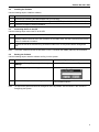
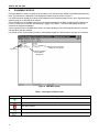
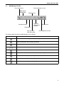
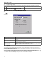
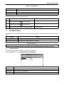
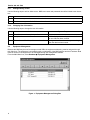
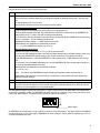
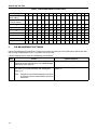
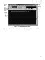
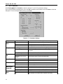
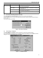
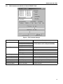
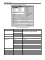
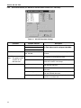
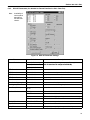
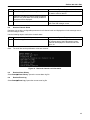
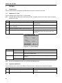
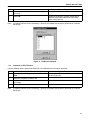
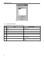
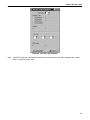
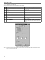
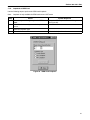
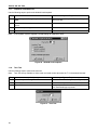
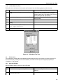
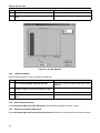
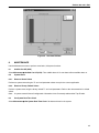
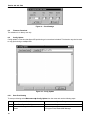
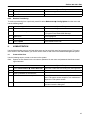
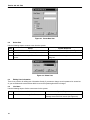
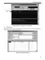
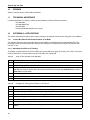
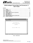
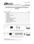
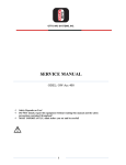
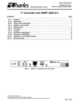
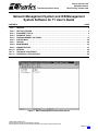
Section 360−381−S02
Telecommunications Group
Equipment Issue 2
Third Printing, October 2006
Network Management System and ICB Management
System Software for T1 User’s Guide
CONTENTS
Part 1.
Part 2.
Part 3.
Part 4.
Part 5.
Part 6.
Part 7.
Part 8.
Part 9.
Part 10.
Part 11.
Part 12.
PAGE
GENERAL . . . . . . . . . . . . . . . . . . . . . . . . . . . . . . . . . . . . . . . . . . . . . . . . . . . . . . . . . . . . . . . . . . . . . . . . . . . . . 2
GETTING STARTED . . . . . . . . . . . . . . . . . . . . . . . . . . . . . . . . . . . . . . . . . . . . . . . . . . . . . . . . . . . . . . . . . . . . 2
EQUIPMENT STATUS . . . . . . . . . . . . . . . . . . . . . . . . . . . . . . . . . . . . . . . . . . . . . . . . . . . . . . . . . . . . . . . . . . . 4
DATABASE TASKS . . . . . . . . . . . . . . . . . . . . . . . . . . . . . . . . . . . . . . . . . . . . . . . . . . . . . . . . . . . . . . . . . . . . . 7
ICB MANAGEMENT SOFTWARE . . . . . . . . . . . . . . . . . . . . . . . . . . . . . . . . . . . . . . . . . . . . . . . . . . . . . . . . 10
STATUS MENU . . . . . . . . . . . . . . . . . . . . . . . . . . . . . . . . . . . . . . . . . . . . . . . . . . . . . . . . . . . . . . . . . . . . . . . . 24
TESTING . . . . . . . . . . . . . . . . . . . . . . . . . . . . . . . . . . . . . . . . . . . . . . . . . . . . . . . . . . . . . . . . . . . . . . . . . . . . . 26
MAINTENANCE . . . . . . . . . . . . . . . . . . . . . . . . . . . . . . . . . . . . . . . . . . . . . . . . . . . . . . . . . . . . . . . . . . . . . . . 35
ADMINISTRATION . . . . . . . . . . . . . . . . . . . . . . . . . . . . . . . . . . . . . . . . . . . . . . . . . . . . . . . . . . . . . . . . . . . . . 37
VERSION . . . . . . . . . . . . . . . . . . . . . . . . . . . . . . . . . . . . . . . . . . . . . . . . . . . . . . . . . . . . . . . . . . . . . . . . . . . . . 40
TECHNICAL ASSISTANCE . . . . . . . . . . . . . . . . . . . . . . . . . . . . . . . . . . . . . . . . . . . . . . . . . . . . . . . . . . . . . 40
APPENDIX A—APPLICATIONS . . . . . . . . . . . . . . . . . . . . . . . . . . . . . . . . . . . . . . . . . . . . . . . . . . . . . . . . . 40
Figure 1. Network Management Software Main Screen
2006 Charles Industries Ltd.
All rights reserved. Printed in United States of America.
The availability of features and technical specifications herein subject to change without notice.
Page 1 of 41
Section 360−381−S02
1.
GENERAL
1.1
Document Purpose
This document describes how to install and use the Intelligent Channel Bank (ICB) Network Management software (NMS).
Note:
Before this software will communicate with an Intelligent Channel Bank (ICB), the ICB must have been
provisioned with an IP address using the craft terminal interface. See the ICB Craft Terminal User’s
Guide for more information.
1.2
Software Function
Use this software to manage the Charles ICB. The NMS system consists of PC software which provides a graphical user interface (GUI) used to provision, control, and monitor multiple 360-80 ICBs.
The PC communicates through an Ethernet interface. To communicate with remote locations, the NMS system
can use the Embedded Operations Channel (EOC) over the T1 if the T1 is using extended superframe (ESF) format. If EOC is not being used, a channel within the T1 for NMS communication must be defined (see Appendix
A—Applications).
When using the secondary T1 card in a normal mode for a Drop and Reinsert application, the NMS can communicate with up to 7 remote ICBs for every locally managed ICB. A locally managed ICB is connected directly to the
same LAN as the NMS Manager PC.
1.3
Software Location
This software should be installed on a PC running Windows 95/98, NT, 2000 or XP and connected to a Charles
360-80 ICB.
1.4
1.5
Software Features
Graphical user interface (GUI) to configure, test, and monitor operation of the system
Provision all cards in the system through on-screen menus
Real-time display of system status and alarms
Continuous update of historical reports
Performance monitoring data and testing capabilities
Reference Documents
3603−81 T1 Controller with SNMP (LT360−381−201)
360−80 ICB Craft Terminal User’s Guide (LT360−381−C01)
3608−80 Secondary T1 Unit (LT360−880−201)
2.
GETTING STARTED
2.1
System Requirements
2
IBM-compatible PC running Windows 95/98, NT, 2000 or XP
50 MB of memory available on the hard drive
8 MB of RAM
VGA display
TCP/IP
Ethernet Port
Section 360−381−S02
2.2
Installing the Software
Use the following steps to install the software:
Step
Action
1.
Insert the CD containing the NMS software into your CD drive.
2.
From the Windows start menu, select Run and type in X:\SETUP (where X is your CD drive letter).
3.
Follow the prompts to continue installation.
2.3
Connecting the PC to the ICB
Use the following steps connect the PC to the ICB:
Step
Action
1.
Using the craft interface, set the ICB’s IP address. To allow remote access outside the ICB’s LAN, the
gateway address should be set to the IP address of the LAN’s router. See the Craft Interface documentation for additional information.
2.
Connect the ICB to the PC/LAN using an Ethernet cable to the J2 rear panel network management
port.
Note:
To connect multiple ICBs see the procedure in the T1 Controller with SNMP (3603-81) documentation.
2.4
Starting the Software
Use the following steps to start the software and log in to the system:
Step
Action
System Response
1.
Select Start Menu " Programs " Charles "
NMSmgr
Opens the NMS main screen (see Figure 1).
2.
Select Setup " Supervisor Log In
Opens the following dialog box:
3.
Enter the default password 123 to log in.
You are logged in as a supervisor, and have access to all menu options.
Note:
The Supervisor password should be changed as soon as possible. See the section in this manual on
Configuring the System.
3
Section 360−381−S02
3.
EQUIPMENT STATUS
Once the software is started, it searches for the status of any ICB previously added to the NMS equipment database. The information is displayed on the Equipment Status screen as shown in Figure 2.
If no ICBs have been added yet, nothing will be displayed in the Equipment Status screen. Go to Equipment Management, page 8, to add ICBs to the system.
On the left-hand side of the NMS main screen, the equipment added to the NMS is displayed with a status icon
next to it. These icons are shown and described in Figure 2 and Table 1. The screen will display all ICBs described in the equipment database.
On the right-hand side of the NMS main screen, the system displays a list of ICB equipment which is communicating properly with the software.
If no activity occurs on the system you will be automatically logged out, and will need to log back in to continue.
Equipment communicating
properly with the software
Status icons
Equipment added
to the NMS for
management
Figure 2. NMS Main Screen
Table 1. Description of Status Icons
Icon
Meaning
Normal Operation
Communication failure with NMS
Major alarm alerted
Minor alarm alerted
Detecting the status of the equipment
4
Section 360−381−S02
3.1
NMS Manager Tool Bar
User Login/Logout
Show equipment as icons
NMS System
Configuration
Equipment list
Cascade windows
Tile windows
Open ICB
management
software
Open the editor
(look at a log file)
Reset screen
Show equipment as a list
The following table describes the NMS Manager tool bar buttons.
Button
Description
Allows a General User to log in to the system /log out the current user.
Allows the Supervisor to set up the Network Management System, method of the equipment communication and necessary parameters.
Cascade the current sub-screens.
Tile the current sub-screens.
Displays the list of the equipment.
Opens the text editor. Use the text editor to read system log files.
Displays the active equipment in the right window as icons.
Displays the active equipment in the right window as a list.
Refreshes the active equipment display (right window).
5
Section 360−381−S02
3.2
Configuring the System
Use this selection to change the supervisor password, and select the equipment communication parameters.
Step
Action
System Response
1.
Select the Editor button
on the Tool Bar
Opens an empty text editor window.
From the Main Menu bar, select Setup NMS System Configure.
OR
Click
Option
Use to...
Login Time Out
Set the amount of time the system will wait before logging the user out automatically.
Change Supervisor Password
Change the supervisor password. The Default password is 123. Maximum
password length is 6 characters.
Log file store date
Select the number of days to keep the log file. The system will automatically
delete the log file after the specified number of days.
3.3
Log Files
The log files record the operation status of the system, such as logins/logouts, the state of the connection between the equipment and the NMS, etc. These files are standard text files which may be read using a text editor,
or using the Editor button on the tool bar.
Up to three log files are generated automatically, once a day, based on system activity and saved in the
\Charles\NMSMgr directory. The file is named according to the file type and generation date with the suffix “.log
”. For example, file name el1018.log is a log file for Oct. 18. See Table 2 for file types.
6
Section 360−381−S02
Table 2. Log File Types
File Name
Stores
ELXXXX.log
ICB equipment status changes, user logins and logouts.
IADXXXX.log
Alarms and loopback changes
LUXXXX.log
NMS user logins and logouts
Use the following steps to read a system log file:
Action
Step
1.
Select the Editor button
on the Tool Bar
2.
Select the Open button
on the tool bar
3.
Select the log file you want to see and click Open
4.
System Response
Opens an empty text editor window.
Opens a list of available log files.
Opens the log file.
DATABASE TASKS
The Database item of the Main Menu Bar is grouped into two categories. Only the supervisor has access to these
items.
Category
User Management
Use to...
Add, delete or edit user information.
Equipment Management Add, delete or update equipment information.
IMPORTANT NOTE
User management tasks performed in this menu apply ONLY to the Network Management software; ICB
software user management tasks are performed from the ICB Administration menu (see page 37).
4.1
User Management
Use this dialog box to add and delete users, and to set passwords.
From the Main Menu bar, select Database User Management.
Field
Description
NAME
Shows the user name.
PASSWORD
Shows the user login password.
NOTES
Memo field (any text).
7
Section 360−381−S02
4.1.1.
Adding/Deleting a User
Use the following steps to add or delete a user. NMS user names and passwords should be limited to ten characters.
Step
Action
1.
To insert a user, press <Insert> or select + from the tool bar.
2.
To delete a user, press <Ctrl> <Del> or select − from the tool bar.
4.1.2.
Changing User Information
Use the following steps to change the user information.
Step
Action
System Response
1.
Move the cursor to the required position.
2.
Modify the data
An “I” is displayed on the first column to indicate
the user data has been modified.
3.
To save the modified data, click on the tool bar.
The sign on the first column changes to a triangle
when the data has been saved.
4.2
Equipment Management
Because the NMS may be used to manage several ICBs, the equipment addressing must be assigned through
this dialog box. The equipment is accessed through a combination of the NMS address and the IP address. Both
must be correct for the equipment to be managed through the management software.
From the Main Menu bar, select Database Equipment Management.
Figure 3. Equipment Management Dialog Box
8
Section 360−381−S02
Use the following steps to insert new ICB equipment:
Step
Action
1.
To add equipment within an existing list:
Move to the line just below where the new equipment should be added and select the + from the toolbar.
To add equipment to the end of a list:
Move past the last item in the list and a blank line will be added.
2.
IAD with Local Connection
Local connection is connected to the same LAN as the management PC.
Enter the NMS address of the ICB. The NMS address of the ICB is determined by the ADDRESS ID
switch setting of the T1 card in the ICB according to the following:
For a unit that is directly connected to the PC/LAN, the address will be the ADDRESS ID switch setting
of the T1 card plus 1. So, the following would be true:
ADDRESS ID switch setting + 1 = NMS address of the ICB
Mathematically, this statement is represented as follows:
4 + 1 = 5 (If the ADDRESS ID switch was set to 4)
IAD with Remote Connection
Remote connection is connected via a T1 to a local connected ICB.
For a remote ICB managed through a local ICB, the NMS address will be the NMS address of the local
ICB, plus the ADDRESS ID switch setting of the remote unit times16. The equation would be:
Local ICB NMS address + (Remote ADDRESS ID switch setting X 16) = NMS address of the remote
ICB
For example, if the local NMS ICB address is 5 and the ADDRESS ID of the remote switch setting is 2,
37 would be the NMS address of the ICB.
Mathematically, this statement is represented as follows:
5 + (2 X 16) = 37.
Note:
The remote ICB ADDRESS ID switch setting must be greater than 0 and less than 8.
Each remote ICB connected to the local ICB in a drop/reinsert configuration must have different ADDRESS ID switch settings.
3.
Enter a description for the new device (see Table 3). Descriptions must be unique for each ICB.
5.
Enter the IP address of the ICB connected to the LAN. For remote units that are managed through a
local ICB, enter the IP address of the local ICB. If an ICB is connected directly to a LAN it can be managed as a local unit regardless of it’s physical location.
The ADDRESS ID switch on the front panel of the T1 card is used to set an ICB NMS address for identification
of this ICB in a network of ICBs. The ADDRESS ID switch consists of 4 switches binary coded and used to set a
unique ICB NMS address. The following figure shows the value of each switch:
1
2
3
4
8
4
2
1
ON
Switch Value
An ADDRESS ID is created by moving a switch (or switches) to the ON position. The figure shows an ADDRESS
ID switch setting of 6 (4+2). The range of ADDRESS ID switch settings is from 0 (when all switches are OFF), to
15 (when all switches are ON).
9
Section 360−381−S02
Table 3. Remote NMS Address Lookup Table
Local NMS Address
1
2
3
4
5
6
7
8
9
10
11
12
13
14
15
16
Local ADDRESS ID
switch setting
0
1
2
3
4
5
6
7
8
9
10
11
12
13
14
15
1
17
18
19
20
21
22
23
24
25
26
27
28
29
30
31
32
2
33
34
35
36
37
38
39
40
41
42
43
44
45
46
47
48
3
49
50
51
52
53
54
55
56
57
58
59
60
61
62
63
64
4
65
66
67
68
69
70
71
72
73
74
75
76
77
78
79
80
5
81
82
83
84
85
86
87
88
89
90
91
92
93
94
95
96
6
97
98
99
100 101 102 103 104 105 106 107 108 109 110 111
7
113 114 115 116 117 118 119 120 121 122 123 124 125 126 127 128
Remote ADDRESS
ID Switch Setting
5.
112
ICB MANAGEMENT SOFTWARE
Use the ICB Management software to configure and monitor the cards used in the ICB system. Menus are available to set up all parameters of the T1 controller and circuit cards.
Use the following steps to open the ICB Management Software:
Step
Action
System Response
1.
Double-click the ICB equipment icon on the connected
equipment list box (right window) of the NMS Manager
main screen (see Figure 2).
Opens the ICB Management log in dialog box.
2.
Enter an ICB user name and password, or the default
user name piad (case-sensitive) and default password 1234.
Opens the main ICB management screen
(Figure 4).
Note:
10
Change the user name and password as soon
as possible. See the Administration section for
instructions.
Section 360−381−S02
Half-size
slot (Channels 25−30,
Secondary
T1)
Pull-down
menus
Card 2 slot
(channels
13−24)
Graphic display
shows which
cards are
installed in
which slots and
the status the
cards are in.
Primary
T1 slot
Message area. Check this area for messages other than alarms, including the response to status requests made from the STATUS menu.
Card 1 slot
(channels
1−12)
Alarm area. Check this area for alarm messages.
Figure 4. Main Network Management Screen
Once you have started the ICB Management System software, you can set/change parameters for any of the
cards in the system.
11
Section 360−381−S02
5.1
Set T1 Parameter
Select Settings"Set T1 Parameter to open the primary T1 card (T1-S) parameter settings.
Once you have finished configuring the card, click OK to activate the new settings, and click Close to close the
dialog box. To cancel changes without saving, click Close.
Figure 5. T1 Parameter Settings
Parameter
CGA Process
Mode
Possible Choices
Description
Normal
Carrier group alarm response characteristics per Pub 43801.
CM2
Carrier group alarm mode 2 (see T1 Controller documentation)
CM3
Carrier group alarm mode 3 (see T1 Controller documentation)
Loop Timing
Internal clock synchronized to incoming T1 signal.
External Timing
Internal clock synchronized to external clock input terminals on
rear panel.
Internal Timing
Internal clock selected as master clock.
LBO (Line BuildOut)
Short Haul: 0 to 660 ft.
Pre-equalization of signal for line conditions.
Long Haul: 0, 7.5, 15, or
22.5 dB
Receive gain control for span line attenuation.
Frame Format
SF
Superframe format
ESF
Extended Superframe format
AMI
Alternate mark inversion
B8ZS
Bit 8 zero suppression
None
No communication to remote unit (non-Charles unit)
Occupy One Channel
One 64K channel is used for communication.
Using Facility Data Links
Communication to remote over FDL (ESF format only)
Timing Source
Line Code
Remote Control
Method (to the
remote ICB)
Automatic Detect No
Mode
Yes
12
SF/ESF must be manually selected
Auto detection of SF/ESF mode, requires loop timing
Section 360−381−S02
Parameter
Operation Mode
5.1.1.
Possible Choices
Description
Normal Mode
Normal T1, or when used with the secondary T1 card allows
for Drop and Insert applications.
Dual T1 Mode
When used with a secondary T1 card, the two T1s function as
two independent T1s
Protection Mode
When used with a secondary T1 card, allows the secondary T1
to be protection for the primary T1.
Status
Protection mode only — indicates which T1 is currently in operation.
Error Second Threshold (protection mode only)
Select Settings " Error Second Threshold to open the error second threshold dialog box.
Use this dialog box to get or set the threshold that determines when the system will switch from the Primary to
the Secondary T1.
Once you have finished, click Close.
Figure 6. Error Second Threshold
5.2
Set Secondary T1 Parameter
Select Settings"Set T1 Parameter to open the secondary T1 card (ST1U) parameter settings.
Once you have finished configuring the card, click OK to activate the new settings, and click Close to close the
dialog box. To cancel changes without saving, click Close.
Figure 7. T1 Parameter Settings
13
Section 360−381−S02
Parameter
Possible Choices
Description
LBO (Line BuildOut)
Short Haul: 0 to 660 ft.
Pre-equalization of signal for line conditions.
Long Haul: 0, 7.5, 15, or
22.5 dB
Receive gain control for span line attenuation.
Bypass Mode
auto bypass
When this option is enabled, the T1 connected to the T1−S is
automatically bypassed or connected to the T1 connected to
the ST1U span when one of the following conditions occurs:
power is lost to the ICB, the T1−S or the ST1U card fails.
forced no bypass
When this option is enabled, the T1 connected to the T1−S is
not bypassed or connected to the T1 connected to the ST1U
when power is lost or there is a card failure. The timeslot allocations remain assigned for the ICB but connections on any
of the “pass through” timeslot assignments are broken if power
is lost or there is a card failure in the ICB.
Bypass button
(manual override
forcing bypass)
If this function is selected from the NMS or craft interface, the ICB will immediately go into
T1 bypass. If the ICB was being managed over a T1, control will be lost and the management screen for that ICB will log out. Re-login is only possible through the craft interface or
through a local connection to the ICB’s rear NMS interface. Restoring normal error-free operation will require removing both the T1−S and ST1U cards. The cards must then be reinserted in order, first the T1−S and then the ST1U.
Remote Control
Method (to the
remote ICB)
None
No communication to remote unit (non-Charles Industries unit)
Occupy One Channel
One 64K channel is used for communication.
Using Facility Data Links
Communication to remote over FDL (ESF mode only)
Frame Format
SF
Superframe format
ESF
Extended Superframe format
AMI
Alternate mark inversion
B8ZS
Bit 8 zero suppression
Line Code
5.3
Set Card Parameters
Parameters available on these dialog boxes will depend upon the cards you use.
Once you have finished configuring the card, click OK to activate the new settings, and click Close to close the
dialog box. To cancel changes without saving, click Close.
Note:
14
For complete descriptions of the card parameters, refer to documentation for the individual cards you are
using.
Section 360−381−S02
5.3.1.
FXO Parameters (for 3658-80 12 Channel FXO/DPT Unit)
Figure 8. FXO Parameter Settings
Parameter
Channel Selection
Possible Choices
1−12 (if in Card 1 slot)
13−24 (if in Card 2 slot)
Description
Select the channel the parameters will be applied
to Each channel can be configured individually
to.
individually.
25−30 (if in half-size slot)
Channel Type
FXO/GS
FXO—ground start
FXO/LS
FXO—loop start
DPT/NORMAL
DPT—normal
DPT/WINK
DPT—automatic wink
Forced Busy
ON or OFF
Select ON to force local channel busy
Channel Impedance
600 or 900 Ohms
Loop matching impedance
CGA Immediate
Idle or Busy
CGA—immediate conditioning
CGA Delayed
Idle or Busy
CGA—conditioning after alarm delay
TTLP Level (dBm)
−10.0 to +6.0 dBm
Transmit TLP level
RTLP Level (dBm)
+6.0 to +10.0 dBm
Receive TLP level
15
Section 360−381−S02
5.3.2.
FXS Parameters (for 3657-80 12 Channel FXS/DPO Unit)
Figure 9. FXS Parameter Settings
Parameter
Channel Selection
Possible Choices
1−12 (if in Card 1 slot)
13−24 (if in Card 2 slot)
Description
Select the channel the parameters will be applied to.
Each channel can be configured individually.
individually
25−30 (if in half-size slot)
Channel Impedance
600 ohms
Loop matching impedance
900 ohms
Ring Mode
interrupted, burst or contin- This option is available only if PLARD D3 or D4 is seuous
lected.
Channel Type
FXS/GS
Ground start
FXS/LS
Loop start
PLARD/D3
Private line automatic ringdown, D3 signaling format.
PLARD/D4
Private line automatic ringdown, D4 signaling format.
MEGACOM/GS/immediate
AT&T Megacom—ground start
MEGACOM/GS/wink
MEGACOM/LS
AT&T Megacom—loop start
DPO
Dial pulse originate
Forced Busy
ON or OFF
Select ON to force local channel busy
CGA Immediate
Idle or Busy
CGA immediate conditioning
CGA Delayed
Idle or Busy
CGA conditioning after alarm delay
TTLP Level (dBm)
−10.0 to +6.0 dBm
Transmit TLP level
RTLP Level (dBm)
−15.0 to +1.0 dBm
Receive TLP level
16
Section 360−381−S02
5.3.3.
E&M Parameters (for 3652-80 12 Channel E&M Unit)
Figure 10. E&M Parameter Settings
Parameter
Channel Selection
Possible Choices
1−12 (if in Card 1 slot)
13−24 (if in Card 2 slot)
Description
Select the channel the parameters will be applied
to Each channel can be configured individually
to.
individually.
25−30 (if in half-size slot)
Channel Type
Type 1−5
Select E&M signaling lead type
Transmission Only
No signaling leads used
Forced Busy
ON or OFF
Select ON to force local channel busy
CGA Immediate
Idle or Busy
CGA immediate conditioning
CGA Delayed
Idle or Busy
CGA conditioning after alarm delay
TTLP Level (dBm)
−19.0 to +13.0 dBm
−19.0 to +7.0 dBm
Transmit TLP level (4-wire mode)
Transmit TLP level (2-wire mode)
RTLP Level (dBm)
−19.0 to +13.0 dBm
−19.0 to +7.0 dBm
Receive TLP level (4-wire mode)
Receive TLP level (2-wire mode)
17
Section 360−381−S02
5.3.4.
OCU-DP Parameters (for 3632-80 12-Channel Office Channel Unit – Data Port)
Figure 11. OCU-DP Parameter Settings
Parameter
Channel Selection
Possible Choices
1−12 (if in Card 1 slot)
13−24 (if in Card 2 slot)
Description
Select the channel the parameters will be applied
to Each channel can be configured individually
to.
individually.
25−30 (if in half-size slot)
Data Rate
2.4K, 4.8K, 9.6K, 19.2K, 56K,
64K, SW 56K
Select the transmission data rate for any/all channel slots.
CSU/DSU
CSU
Convert non-latching DSU loopback codes from
the network to CSU loopback codes.
DSU
Normal operating position. Allows DSU loopback
codes to be sent to 4-wire loops.
Error Correction
Enable BCH error correction. Available for 19.2K,
56K and 64K data rates.
Alternate CMI Available
Enable alternate idle code. Available for SW 56K
data rates.
Zero Code Suppression
Enable suppression of zero codes. Available for
64K and SW 56K data rates.
Latching Loopback Enable
Enable send and detect latching loopback codes.
Available for all data rates.
Note:
Options
18
This option is NOT
available for the
64K data rate.
Section 360−381−S02
5.3.5.
Note:
DSU-DP Parameters (for 3633-80 12 Channel Data Service Unit—Data Port)
Availability of
some options
depends on
the data rate
chosen.
Figure 12. DSU-DP Parameter Settings
Parameter
Channel Selection
Selection
1−12 (in Card 1 slot)
13−24 (in Card 2 slot)
Description
Select the channel(s) the parameters will be applied to.
Each channel can be configured individually.
individually
25−30 (in half-size slot)
CTS Control
Enable/disable
Forces clear-to-send to selected level.
DSR Control
Enable/disable
Forces data-set-ready to selected level.
DCD Control
Enable/disable
Forces data carrier detect to selected level.
RTS Force On
Enable/disable
Forces request-to-send to ON
Error Correction
Enable/disable
BCH error correction.
Zero Code Suppression
Enable/disable
Converts a zero data byte to 18 hex sent to network.
Latching Loopback Enable Enable/disable
Enables detection of latching loopback codes.
Data Rate (Kilobits)
2.4, 4.8, 9.6, 19.2, 56
or 64
Select the transmission data rate.
Interface Mode
RS530
EIA standard serial interfaces.
V.36/RS449
EIA standard serial interfaces.
V.35
ITU standard for high-speed synchronous data exchange.
RS232
EIA standard serial interface.
ASYNC/SYNC Mode
ASYNC or SYNC
Synchronous or asynchronous data transmission.
Stop Bit Shortened
12.5% or 25%
Async mode 12.5% or 25% shortened stop bits.
Parity Bit
No or Yes
Select parity or no parity for async mode only.
19
Section 360−381−S02
Stop Bit
1 or 2
Select 1 or 2 stop bits for async mode only.
7/8 Bits Mode
7 or 8
Select 7 or 8 data bits for async mode only.
5.3.6.
ISDN Parameters (for 3638-80 Quad Circuit ISDN)
Figure 13. ISDN Parameter Settings
Parameter
Possible Choices
Description
Composite Clock
Source
Channels 1−4 (if in card 1 slot)
Channels 13−16 (if in card 2 slot)
Channels 25−26 (if in half-size
slot)
None
Select the source of the composite clock output on
the rear panel.
Channel Selection
1−4 (if in card 1 slot)
13−16 (if in card 2 slot)
25−26 (if in half-size slot)
Select the channel(s) the parameters will be applied
to. Each channel can be configured individually.
Channel Type
D
Overhead channel only.
1B + D
One data/voice channel plus overhead channel.
2B + D
Two data/voice channels plus overhead channel.
Options
Sealing Current
ON/OFF (LULT only).
Mode
LULT
RT mode.
LUNT
COT mode.
20
Section 360−381−S02
5.3.7.
56/64xN Parameters (for 3634-80 6-Circuit 56/64xN Data Service Unit—Data Port)
Figure 14. 56/64xN DSU-DP Parameter Settings
Selection
Parameter
Channel Selection
1−6 (if in card 1 slot)
13−18 (if in card 2 slot)
Description
Select the channel(s) the parameters will be applied to.
Each channel can be selected individually.
individually
25−27 (if in half-size slot)
Number of Timeslots
1−24
Depends on desired bandwidth and timeslots allocated.
Channel Type
RS530
Select serial interface connection type.
V.35
V.36/RS449
RS232
Base Setting
56K or 64K
Data rate.
Idle Mode
11111110 or 11111111
Select idle mode data pattern.
CTS Control
Enable/disable
Forces clear-to-send to selected level.
DSR Control
Enable/disable
Forces data-set-ready to selected level.
DCD Control
Enable/disable
Forces data carrier detect to selected level.
Zero Code Suppression Enable/disable
Converts a zero data byte to 18 hex sent to the network.
PRTS
Enable/disable
Permanent request-to-send forces request-to-send active
and to continuously send data.
External Clock
Enable/disable
Select external input as a clock source.
V.54 Loopback Enable
Enable/disable
Allow transmission and detection of loopback codes.
DTE’s LL Enable
Enable/disable
Allow local loop to be enabled by DTE interface.
21
Section 360−381−S02
5.3.8.
Ethernet Router Parameters (for 3641-80 and 3648-80)
Figure 15. Ethernet Router Parameter Settings
Parameter
Possible Choices
Description
Number of Timeslots
1−24
Depends on desired bandwidth and timeslots allocated.
Base Setting
56K or 64K
Data rate.
5.4
Time Slot Allocation
Use this dialog box to change the location of a channel within the T1 signal time slots. This dialog box is also
used for drop and insert applications.
Select Settings"Time Slot Allocation
Figure 16. Setting the Time Slot Allocation
22
Section 360−381−S02
Use the following steps to change time slot allocation. Time slots and chassis slots must be unallocated before
they can be allocated. The first three steps are followed to unallocate chassis slots (channels) from time slots. the
last two steps are followed to allocate chassis slots (channels) to time slots.
Step
Action
System Response
1.
Click Delete.
2.
Click on the chassis slot that you want to change
and respond Yes when asked to confirm.
3.
Repeat steps 1 and 2 for any other chassis slots
you want to unallocate.
4.
Click on the unallocated chassis slot you want to
allocate.
The selected chassis slot will turn yellow.
5.
Click on the T1 time slot you want to allocate the
chassis slot to.
The selected chassis slot and time slot(s) will turn
light green.
Note:
The chassis slot will turn white, and its corresponding T1 time slot(s) will darken.
For chassis slots that use multiple time
slots, click on the first T1 timeslot to be
used.
Note:
If a chassis slot does not have a card plugged in, the chassis slot channels will not be displayed.
5.5
Time Slot Mode (only with Secondary T1 Unit Installed)
Use this dialog box to change data that will be sent to a T1 time slot that is not allocated on the other T1. Changing the time slot mode provisioning does not affect the operation of the channel bank unless the T1 is set to normal (drop & re-insert) mode.
Note:
Time slots that are not dropped must be set to broadcast on both the Primary and Secondary T1 time
slots to pass data from one T1 to the other T1. Time slots to be blocked between T1s should have the
time slot mode set to idle on both Primary and Secondary T1 time slots.
Select Settings"Set Time Slot Mode
Figure 17. Setting the Time Slot Mode
23
Section 360−381−S02
Use the following steps to change the time slot mode:
Step
Action
1.
Select the mode you want the time slot set to.
2.
Select the time slot you want to edit.
3.
Repeat steps 1 and 2 for any other slots you want
to change.
4.
Click Close to save changes and close the dialog
box.
6.
System Response
Changes the slot information to the corresponding
color.
STATUS MENU
Use the following sections to check the system status. Once retrieved, system status will be displayed in the main
screen as shown in Figure 18.
Figure 18. Screen showing retrieved status in the Message area and the Alarm area
6.1
Retrieve T1 Parameter
Select Status"Retrieve T1 Parameter. Retrieves the parameters of the T1 card and displays them in the Message area of the main screen.
6.2
Retrieve T1 Alarm Status
Select Status"Retrieve T1 Alarm Status. Retrieves any current alarms on the T1 card and displays them in the
Alarms area of the main screen.
6.3
Retrieve Inventory Data
Retrieves basic data about any card in the system.
Use the following steps to retrieve inventory data.
24
Section 360−381−S02
Step
Action
1.
Select Status"Retrieve Inventory Data.
2.
Select the card that you want to retrieve inventory
data for. Only cards which are actually installed in
the system will be displayed.
3.
Click OK.
6.4
System Response
Opens a dialog box asking you to select the card
you want to retrieve data for.
Displays the card firmware version in the message
area of the ICB manager screen.
Retrieve Channel Status
Retrieves a list of all the configurable parameters for all channel cards and displays them in the message area of
the ICB manager screen.
Use the following steps to retrieve the channel status.
Action
Step
1.
Note:
Select Status"Retrieve Channel Status.
System Response
Displays the channel status of all installed cards in
the message area of the ICB manager screen.
Channels are displayed in numerical order. See
Figure 19.
The scroll bar can be positioned to view each channel.
Figure 19. Retrieved channel card information
6.5
Retrieve Alarm History
Select Status"Alarm History. Opens the current alarm log file.
6.6
Retrieve Event Log
Select Status"Event Log. Opens the current event log file.
25
Section 360−381−S02
7.
TESTING
7.1
Loopback Test
Use the Loopback tests to troubleshoot problems when an alarm is reported on the card.
7.1.1.
Loopback of T1 Card
Use the following steps to perform the T1 card loopback.
Note:
Loopback tests will affect the service being provided. Loopback tests will not function if there is an alarm
present on the ICB.
Step
Action
System Response
1.
Select Loopback Test " Loopback of T1 Card
2.
Select the type of loopback you want to perform
(Line or Payload)
3.
Select the loopback location (near end or far end)
4.
Select Loopback
Opens the Primary T1 Card Loopback dialog box
(see Figure 20).
Initiates the loopback. Results will be displayed in
the alarm status area of the main screen (see
Figure 18).
Figure 20. T1 Card Loopback
Parameter
Type
Location
Possible Choices
Use to...
Line
Loop T1 (24 DS0s and overhead).
Payload
Not available for Near End. Loop T1 ICB to itself (available in ESF
mode only) (24 DS0s only).
Near End
Loop local T1. This option is not available when payload loopback is
selected.
Far End
Loop T1 at remote ICB.
Note:
Far end line loopbacks will block far end ICB Remote Management.
7.1.2.
Loopback of E&M Card
Use the following steps to perform the E&M card loopback (this is a bidirectional network/local loopback).
Step
Action
System Response
1.
Select Loopback Test " Loopback of EM Card
Opens the EM Loopback/Release dialog box (see
Figure 21).
2.
Select the Loopback or Release tab.
26
Section 360−381−S02
Step
Action
System Response
3.
Check the box beside the channel number(s) you
are using.
4.
Select OK
Note:
Initiates the loopback or release. Results will be
displayed in the alarm status area of the main
screen (see Figure 18).
A loopback channel can be “forced busy”. However, a loopback test cannot be performed on a channel
that is busy.
Figure 21. E&M Card Loopback
7.1.3.
Loopback of FXO/FXS Card
Use the following steps to perform the FXO/FXS card loopback (this is a network loopback).
Action
Step
1.
Select Loopback Test " Loopback of FXO/FXS
Card
2.
Select the Loopback or Release tab.
3.
Check the box beside the channel number(s) you
are testing.
4.
Select OK
Note:
System Response
Opens the FXO/FXS Loopback/Release dialog
box (see Figure 22).
Initiates the loopback or release.
A loopback channel can be “forced busy”. However, a loopback test cannot be performed on a channel
that is busy.
27
Section 360−381−S02
Figure 22. FXO/FXS Card Loopback
7.1.4.
Loopback of OCU-DP Card
Use the following steps to perform the OCU-DP card loopback.
Step
Action
System Response
1.
Select Loopback Test " Loopback of OCU-DP
Card
2.
Select the the channel you want the loopback test
run on.
3.
Select the loopback type.
4.
Select the loopback location (near- or far-end).
5.
Set the test time. This defines the duration of the
test.
6.
Select 2047 Pattern enable or disable.
If enabled, generates a 2047 pattern to be looped
back for analysis.
7.
Select Loopback
Initiates the loopback or release. If no time slot is
assigned to the chassis slot, loopback cannot be
enabled.
28
Opens the OCU-DP Loopback/Release dialog box
(see Figure 23).
Section 360−381−S02
Figure 23. OCU-DP Card Loopback
Note:
OCU-DP far and near end loopback generators do not operate when the ICB is equipped with a Secondary T1 module in Protect mode.
29
Section 360−381−S02
7.1.5.
Loopback of DSU-DP Card
Use the following steps to perform the DSU-DP card loopback.
Action
Step
System Response
1.
Select Loopback Test " Loopback of DSU-DP
Card
Opens the DSU Loopback/Release dialog box
(see Figure 24).
2.
Select the the channel you want the loopback test
run on.
3.
Select the loopback type.
4.
Select the loopback location (near- or far-end).
5.
Set the test time. This defines the duration of the
test.
6.
Select 2047 Pattern enable or disable.
If enabled, generates a 2047 pattern to be looped
back for analysis.
7.
Select Loopback
Initiates the loopback or release. If no time slot is
assigned to the chassis slot, loopback cannot be
enabled.
Figure 24. DSU-DP Card Loopback
Note:
30
DSU-DP far and near end loopback generators do not operate when the ICB is equipped with a Secondary T1 module in Protect mode.
Section 360−381−S02
7.1.6.
Loopback of ISDN Card
Use the following steps to perform the ISDN card loopback.
Note:
Loopback is only available for ISDN cards set to LUNT mode.
Step
Action
System Response
1.
Select Loopback Test " Loopback of ISDN
Card
2.
Select the the channel you want the loopback test
run on.
3.
Select the loopback type.
4.
Select OK
Opens the ISDN Loopback/Release dialog box
(see Figure 25).
Initiates the loopback or release.
Figure 25. ISDN Card Loopback
31
Section 360−381−S02
7.1.7.
Loopback of 56/64xN Card
Use the following steps to perform the 56/64xN card loopback.
Action
Step
System Response
1.
Select Loopback Test " Loopback of 56/64xN
Card
2.
Select the the channel you want the loopback test
run on.
3.
Select the loopback type.
4.
Select Activate
Note:
Opens the 56/64xN Loopback/Release dialog box
(see Figure 26).
Initiates the loopback or release.
V.54 loopback must be engaged on 64xN settings for loopback to work.
Figure 26. 56/64xN Card Loopback
7.1.8.
Tone Test
Use the following steps to perform the tone test.
Note:
Tone Test is only available on Voice cards and sends a short tone onto the T1 in the selected channel..
Step
Action
System Response
1.
Select Loopback Test " Tone Test
2.
Select the channel number.
3.
Select OK
Opens the Tone Test dialog box (see Figure 27).
Initiates the test. Results will be displayed on a
Tone Test Results pop-up screen.
Figure 27. Tone Test
32
Section 360−381−S02
7.1.9.
1 kHz 0dbm0 Test Tone
During this test a continuous tone is present until released. Use the following steps to perform the test.
Step
Action
System Response
1.
Select Loopback Test " 1KHz 0dbm0 Test
Tone
If multiple voice cards are installed, asks you to
select which one you want to test. Go to step 2.
Otherwise, opens the 1 KHz 0dbm0 Test Tone dialog box (see Figure 28). Go to step 3.
2.
Select the card you want to test and click OK
Opens the 1 KHz 0dbm0 Test Tone dialog box
(see Figure 28).
3.
Select the Operation or Release tab.
4.
Check the box beside the channel number you are
testing.
5.
Select the direction (XMT or RCV).
Note:
6.
XMT is toward the T1.
Select OK
Initiates the test or release.
Figure 28. 1KHz 0dbm0 Test Tone
7.2
Performance
The performance monitor gathers and displays the performance history of the system over a 30-day period. Errored seconds (ES), severely-errored seconds (SES), and failed seconds (FS) are displayed graphically in
15-minute or 1-day intervals.
7.2.1.
One Day PM Data
Use the following steps to look at one day of PM data:
Step
Action
1.
Select Performance " One Day PM Data
2.
Select whether you want to check today’s data or
a previous day’s data.
System Response
Opens the One-Day PM data screen with no data
displayed.
33
Section 360−381−S02
Step
Action
System Response
3.
Click Retrieve.
Displays the data in a graph (see Figure 29).
4.
Click Close when you are done looking at the
data.
Figure 29. One Day PM Data
7.2.2.
15-Minute PM Data
Use the following steps to look at 15 minutes of of PM data:
Step
Action
5.
Select Performance " 15-Minute PM Data
6.
Select whether you want to check the current 15
minutes of data or a previous 15 minutes of data.
7.
Click Retrieve.
8.
Click Close when you are done looking at the
data.
7.2.3.
System Response
Opens the 15-minute PM data screen with no data
displayed.
Displays the data in a graph (see Figure 30).
Reset Today PM Counter
Select Performance " Reset Today PM Counter. Reset the daily performance monitor counter.
7.2.4.
Reset Current Quarter PM Counter
Select Performance " Reset Current Quarter PM Counter. Reset the 15-minute performance monitor counter.
34
Section 360−381−S02
Figure 30. 15-minute PM Data
8.
MAINTENANCE
Use the Maintenance menu to perform some basic, full-system functions.
8.1
Audible Cut Off (ACO)
Select Maintenance"Audible Cut Off (ACO). Turn audible alarm off. A new alarm will turn audible alarm on.
8.2
System Reset
8.2.1.
Reset to Stored Values
Performs a system reset using the T1 and card parameter values set up for the current application.
8.2.2.
Reset to Factory Default Values
Perform a system reset using the factory default T1 and card parameters. Refer to the documentation for default
values.
Note:
A system reset will clear all configuration information in the Community table and the Trap IP table.
8.3
Set System Real-Time Clock
Select Maintenance"Set System Real-Time Clock. Set date and time for the system.
35
Section 360−381−S02
Figure 31. Clock Settings
8.4
Firmware Download
This selection is for factory use only.
8.5
Config Update
Config update is a function that allows ICB provisioning to be saved and reloaded. This function may also be used
to copy provisioning to multiple ICBs.
Figure 32. Config Update
8.5.1.
Save Provisioning
To save provisioning select Maintenance " Config Update from the menu and use the following steps.
Step
Action
System Response
1.
Select Save System Config
A new screen will appear.
2.
Choose a directory where the file is to be
saved
The default directory is:
C:\Program Files\Charles\NMS Manager
36
Section 360−381−S02
Step
Action
System Response
3.
Enter a file name
The file name appears with the extension .dat
4.
Select Save
The file is saved.
8.5.2.
Retrieve Provisioning
To retrieve provisioning from a previously saved file select Maintenance " Config Update from the menu and
use the following steps.
Step
Action
System Response
1.
Select Load File
A new screen will appear.
2.
Choose the directory where the file is saved
The default directory is:
C:\Program Files\Charles\NMS Manager
3.
Select a file
File is highlighted.
4.
Select Open
5.
Select Update
9.
File is loaded into the ICB.
ADMINISTRATION
Use the Administration menu to add and delete users and to see which users have system access. This menu
refers ONLY to the ICB software; you cannot use this menu to add users to the Network Management system.
9.1
Create a New User
Use the following steps to create a new user on the system.
Note:
Spaces are not allowed in the user name or password. A user name and password should not exceed
eight characters.
Step
Action
System Response
1.
Select Administration " Create New User
Opens the Create New User dialog box (see Figure 33).
2.
Enter the new user’s name.
3.
Enter a password for the new user.
4.
Select the new user’s security level.
Guest= Allows access to status and performance data.
User= Full system access except for user maintenance.
Supervisor= Full system access.
5.
Select OK
Enters the new user into the system, confirms the password and closes the dialog box.
37
Section 360−381−S02
Figure 33. Create New User
9.2
Delete User
Use the following steps to remove a user from the system:
Action
Step
System Response
1.
Select Administration " Delete User
Opens the Delete User dialog box (see Figure 34).
2.
Select the user’s name from the pull-down menu.
3.
Select Delete and respond Yes to the confirmation Deletes the user from the system and closes the
screen.
dialog box.
Figure 34. Delete User
9.3
Editing User Information
There is no provision for editing user information directly. If you want to change a user’s password or access level, you must delete the user and then add the user to the system again with the changes.
9.4
List Users
Use the following steps to list the current users in the system:
Step
1.
38
Action
Select Administration " List Users
System Response
Retrieves and displays a list of the current users in the
Message area of the main screen (see Figure 35).
Section 360−381−S02
List of current
users
Figure 35. Main screen showing a list of current users
9.5
Channel Memo
Use the channel memo dialog box to store information about individual channels. Information that may be stored
includes channel name, location, and installation date.
Figure 36. Channel Memo dialog box
39
Section 360−381−S02
10.
VERSION
Select to see the version of ICB software installed.
11.
TECHNICAL ASSISTANCE
If technical assistance is required, contact Charles Industries’ Technical Services Center at:
847-806-8500
847-806-8556 (FAX)
800-607-8500
[email protected] (e-mail)
12.
APPENDIX A—APPLICATIONS
This section describes procedures which require settings to be made at more than one dialog box in the software.
12.1
Local ICB to Remote ICB Communication in SF Mode
The following procedure sets up a single channel for the NMS to communicate with remote 360-80 ICBs. This
procedure is only necessary when ESF framing is NOT being used. Perform this procedure from the local ICB
over the T1 line.
12.1.1. Switching from ESF to SF Framing
To establish communication from the local ICB to the remote ICB when using SF framing, one of the T1 time slots
must be allocated for communication from the local ICB to the remote ICB.
12.1.1.1
Verify a Time Slot that is not Allocated
Action
Step
1.
Open the ICB software for the local ICB.
2.
Select Settings " Time Slot Allocation.
3.
Verify that an open time slot exists (time slot box not green). If all time slot boxes are green, select Delete and then select a chassis slot to disconnect from the time slot (both the Chassis Slot box and the
Time Slot box will be dark).
4.
Close the dialog box.
5.
Open the ICB software for the remote ICB.
6.
Perform steps 2−4 above, selecting the same time slot you selected for the local ICB.
12.1.1.2
Configure for “Occupy One Channel” in SF Format
Action
Step
1.
Open the ICB software for the remote ICB.
2.
Select Settings " Set T1 Parameter to open the primary T1 card parameters.
3.
Under Remote Control Method, select Occupy One Channel.
4.
Select the Modify, and select the channel to use for communication. The channel must not be in use.
5.
Under Frame Format, select SF.
6.
Under Automatic Detect Mode, select NO.
7.
Click OK to close the T1 Parameter dialog box. Both the local ICB and the remote ICBs will display AR
(alarm).
40
Section 360−381−S02
8.
Open the local ICB software.
9.
Perform steps 2−7 above. All alarms should clear, and communication will be established.
12.2
Configure for “Using Facility Data Link” in ESF Format
Step
Action
1.
Open the ICB software for the remote ICB.
2.
Select Settings " Set T1 Parameter to open the primary T1 card parameters.
3.
Under Automatic Detect Mode, verify that NO is selected.
4.
Under Frame Format, select ESF.
5.
Under Remote Control Method, select Using Facility Data Link.
6.
Click OK to close the T1 Parameter dialog box. Both the local and the remote ICBs will display AR
(alarm).
7.
Open the local ICB software.
8.
Perform steps 2−6 above. All alarms should clear, and communication will be established.
41