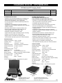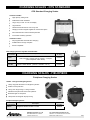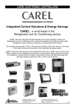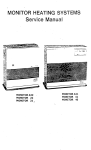
1
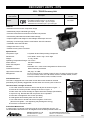
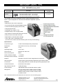
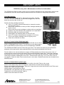
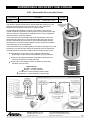
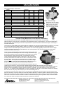
VACUUM PUMPS
CPS Vacuum Pumps – Direct Drive
Airefrig
Description
Part Number
Vacuum Pump - 2 stage
VP2DA
VP2DE
VP3DA
VP4DE
VP6DE
VP8D
VP10DA
VP10D
VP12D
Litres Per
Minute
45
Micron
H.P.
10
1/4
List Price
Ex GST
$528.00
Vacuum Pump - 2 stage
48
10
1/4
$528.00
Vacuum Pump - 2 stage
75
10
-
$742.50
Vacuum Pump - 2 stage
96
10
1/2
$742.50
Vacuum Pump - 2 stage
144
10
1/2
$973.50
Vacuum Pump - 2 stage
192
10
2/3
$1,305.00
Vacuum Pump - 2 stage
236
10
3/4
$1,961.85
Vacuum Pump - 2 stage
240
10
3/4
$1,961.85
Vacuum Pump - 2 stage
288
10
1.0
$2,198.64
Airefrig
Part Number
L340
L341
CAB001
VG200
AVT45
Vacuum Pump Oil
(945 mls)
List Price
Ex GST
$21.32
Vacuum Pump Oil
(3.78 Litre)
$42.77
Tee 1/4M/F x 1/4 Female Flare Knurl x 1/4 M/F (suit VG200)
$39.51
VPASU
Vac Pump Anti-Siphon Valve Kit (c/w 1/4,3/8,1/2MF Adaptors)
$108.24
Description
CPS A/C Power Cord for Vacuum pumps & Recovery units
CPS Vacuum Gauge with Digital Display
VG200 – Vacuum Gauge
Advanced 5 digit LCD display
Reads microns, Torr, in/hg or
mBar at a touch of a button.
Withstand 400PSI pressure.
Carry case & hook included.
P.O.A.
$640.92
AVT45
Vacuum Pump Maintenance and Service Information
The vacuum pump consists of two cascaded stages driven by a common shaft. The first stage (or roughing stage)
takes air/vapour via the inlet port, compresses it and exhausts through an exhaust port. The second stage takes
from the inside of this exhaust port and also compresses the vapour and then exhausts this vapour out through a
second exhaust port.
The purpose of a gas ballast valve (where fitted) is to bleed dry air into the second chamber at 0 PSIG or very close
to it. This way the second stage draws in vapour, it‘s pressure is reduced and vapour is removed from the
oil/vapour as the saturated vapour pressure is lowered. The second stage typically is also fed oil from the pump
reservoir and when the pump is under ballast this oil is also exposed to the reduced pressure and this assists
removal of moisture from the oil.
As the pump is working slightly harder when under ballast, more heat
is also generated so allowing the oil which is being circulated through
the second chamber to warm up and return to the reservoir so raising
the temperature of the reservoir faster. This enables the pump to
reach operating temperature faster. Remember, if the oil is cold the
moisture pulled back can blend with the cold oil, overload the oil with
moisture and in short order can wreck the pump. The idea is to get
the pump HOT, this way moisture hits hot oil and is pushed straight
out of the pump. A hot pump works better and will last longer than a
pump which is never allowed to reach operating temperature.
To start and use the pump, ensure the ballast and inlet ports are both
closed, turn the pump on. Once the pump is started open the ballast valve and leave to run like this for
approximately ½ hour. When ready to use, close the ballast and connect to the system to be evacuated, open the
suction port and evacuate the system. After the vacuum is complete, it is good practice to run the pump for a
further 10 – 15 minutes under ballast again to remove impurities from the oil. An even better practice is to actually
drain the oil from the pump, allow the pump to cool before adding fresh oil.
To drain the oil from the pump ensure it is on a level surface (preferable with the oil warm) and remove the drain
plug from the pump. You may need to unscrew the exhaust chimney or oil inlet in order to allow air into the pump to
allow oil flow. Inspect the oil for cloudiness, impurities and foreign lumps. When refilling, ensure pump is cool and
refill to the correct level. DO NOT overfill !! If water is noticed in the pump you may need to refill, run under ballast
for a short time, drain and refill in order to ensure the moisture is removed.
Not all pumps are identical in operation, always, as a first step, read the instructions that come with the pump.
AIREFRIG AUSTRALIA PTY LTD
RECOMMENDED LIST PRICES
A.B.N. 95 008 761 573
ALL PRICES ARE EXCLUSIVE OF GST
SUBJECT TO CHANGE WITHOUT NOTICE
EFFECTIVE MARCH 2014
526
VACUUM PUMP PERFORMANCE CHECK
Vacuum Pump Quick Performance Check
This document describes a simple and quick method to conduct a basic operational and performance
check on a vacuum pump.
* Please ensure that your vacuum pump is in sound electrical and mechanical
condition prior to applying electrical power and operating.
1. Check the oil level in the sight glass is between the minimum
and maximum level indicators, oil should look clean and clear if
the pump has been recently serviced. Oil colour can vary from
water clear to honey colour depending on the brand, but it should
look translucent and not be dark or opaque which could indicate
the presence of contaminants.
2. Ensure the pumps flare inlet port connection that you will be
using is clean and dry, give it a wipe with a clean dry cloth to
remove any debris.
3. Attach your ball valve (ensure the tap is closed) with the vacuum gauge directly to the inlet port.
In some cases you may require the 3/8" female to 1/4" male adaptor depending on the individual vacuum pumps
inlet configuration. In some case you may also need to use the supplied 1/4" ‗ T ‘ adaptor and cap the unused ‗ T ‘
adaptor 1/4" male port.
4. Start the pump and allow it to run for a few minutes before opening the ball valve. Allow the pump to evacuate
the ball valve and vacuum gauge assembly for a couple of minutes prior to checking the vacuum reading.
Older model vacuum pumps may require a longer warm up period due to their internal construction, be guided by
the pumps owner who should know his equipment.
5. The best practice is to always close the ball valve prior to stopping the pump to reduce the chance of oil
migrating into the vacuum gauges sensitive sensor assembly.
6. If the reading is above 400 microns the pump could be internally worn, in need of an oil change, repairs, have an
air leak or perhaps faulty port caps on unused inlets.
Setup requiring the
3/8" to 1/4" adaptor
Typical test setup
(
AIREFRIG AUSTRALIA PTY LTD
RECOMMENDED LIST PRICES
A.B.N. 95 008 761 573
ALL PRICES ARE EXCLUSIVE OF GST
SUBJECT TO CHANGE WITHOUT NOTICE
EFFECTIVE MARCH 2014
527
VG200 VACUUM GAUGE SERVICING
VG200 Vacuum Gauge Servicing
The VG200 are simple to use precision digital readout vacuum gauges able to read in Hg",
microns, Torr and mbarr selectable by pressing the units button.
In order to maintain peak performance some simple periodic maintenance is required
to ensure the units internal vacuum sensor assembly remains as clean as possible.
We recommend a quick visual inspection of the sensor assembly gasket daily and cleaning
whenever you notice any oil on the gasket. This brochure outlines this simple cleaning procedure.
Ensure you have access to a vacuum pump prior to cleaning, you will need to connect your VG200
to a vacuum pump for at least 15 minutes to evacuate moisture from the sensor immediately after cleaning.
Routine cleaning and service:
1. Remove the valve core depressor (if fitted) and the black HXG gasket with needle nose pliers.
2. Inject methylated spirits into the sensor to fill the gasket cup, a standard medical syringe is perfect for this task.
3. Hold the unit in one hand and place your thumb over the gasket cup area.
4. Using your hand to create a swirling motion will encourage the methylated spirits to enter the sensor chamber.
5. Repeat from Step 2 until the sensor is full and will not take anymore liquid.
6. Use a continuous swirl motion with the unit to create swirling effect of the solution in the housing for 15 seconds.
7. Invert and flick the unit (sensor out) to eliminate the bulk of the solution from the sensor assembly.
8. Insert a new HXG gasket (flat surface down 45˚ chamfer out) and re-fit the HXD valve core depressor if required.
Place your VG200 on a vacuum pump for at least 15 minutes to evacuate any remaining moisture.
9. When not in use store your vacuum gauge in it‘s padded protective bag. As with any electronic device if it is
going to be stored for an extended period of time consider the removal of the batteries.
Precautions with the VG200:
• There are no user serviceable parts inside the case.
• Keep away from dust, dirt and water.
• Clean the plastic case with a soft moist cloth. DO NOT USE SOLVENT BASED CLEANERS.
• Regularly inspect the HXG gasket seal for signs of oil, if oil is evident perform the above cleaning procedure.
AIREFRIG AUSTRALIA PTY LTD
RECOMMENDED LIST PRICES
A.B.N. 95 008 761 573
ALL PRICES ARE EXCLUSIVE OF GST
SUBJECT TO CHANGE WITHOUT NOTICE
EFFECTIVE MARCH 2014
528
RECOVERY UNITS - CPS
CPS - TR21E Recovery Unit
Airefrig
Part Number
List Price
Ex GST
Description
Oil–Less Refrigerant Recovery Machine
Flow Rate for Direct Vapour : Up to 56 kg/hr
Flow Rate for Direct Liquid : Up to 271 kg/hr
Flow Rate for Push Pull Liquid : Up to 768 kg/hr
TR21E
$2,678.40
Features
• Maintenance free oil-less compressor design
• Aesthetically unique industrial type styling
• Precision machined from aluminum and steel components
• Permanently lubricated and sealed main bearings
• Improved piston seal design for less leakage and deeper vacuums
• 550 psig / 37.9 Bar high pressure cutoff switch with LED indicator
• Cleanable 100 mesh inlet filter
• Weighs less than 11.3 kg
• Fastest recovery rates in its class
Specifications
Compressor Type:
2 Cylinder Oil-less Reciprocating Compressor
Dimensions:
Weight:
15cm Wide x 30cm Long x 23cm High
11.3 kg / 25 lbs.
Operating Temperature Range: 0˚C to 49˚C
Power Source:
Power Consumption:
220-240V 50/60Hz
850 W
Filtration:
Overload Protection:
Cleanable 100 - mesh screen integrated into Suction Port
Motor Thermally Protected
High Pressure Shut-Off:
Refrigerants:
550 psig / 37.9 Bar
R-12, R-134a, R-401C, R-406A, R-500, R-401A, R-409A, R-401B, R-412A,
R-411A, R-407D, R-22, R-411B, R-502, R-407C, R-402B, R408A, R-509,
R-407A, R-404A, R-402A, R-507, R-407B, R-410A
Filter Maintenance
The TR21 is equipped with a 100-mesh screen filter which should be checked
periodically as a partially clogged filter will slow down the recovery rate of this unit.
Check the filter cartridge as follows
1. Use a 5/8" socket or wrench to remove the IN port as shown in Figure – 1
2. Remove the suction port-filter cartridge as shown in Figure - 2
3. Either clean the current cartridge or replace with new cartridge (P/N CRXF3)
4. Inspect O-ring. Re-lubricate with compressor oil or equivalent
5. Place filter cartridge back into suction port fitting
6. Hand tighten this assembly back onto the TR21
7. Use a 5/8 socket or boxed end wrench to tighten 1/8 of a turn
(Do Not over tighten – over tightening may damage the O-ring)
8. Check the connection for leaks
Piston Seal Maintenance
In cases where a customer is using this unit for virgin refrigerant recovery, it is
recommended to add 0.25 ounce of refrigerant oil to the inlet port before each use.
AIREFRIG AUSTRALIA PTY LTD
RECOMMENDED LIST PRICES
A.B.N. 95 008 761 573
ALL PRICES ARE EXCLUSIVE OF GST
SUBJECT TO CHANGE WITHOUT NOTICE
EFFECTIVE MARCH 2014
529
RECOVERY UNITS - CPS
CPS – CR500E Recovery Unit
Airefrig
Part Number
List Price
Ex GST
Description
Oil-Less Refrigerant Recovery Machine
Flow Rate for Direct Vapour : Up to 20 kg/hr
Flow Rate for Direct Liquid : Up to 42 kg/hr
Flow Rate for Push Pull Liquid : Up to 187 kg/hr
CR500E
$2,386.20
The CR500E is an oil-less refrigerant recovery machine designed to pump
liquid or vapour refrigerant for commercial & residential refrigeration systems.
Features
• Maintenance free oil-less compressor
• On board SUCTION and DISCHARGE gauges.
• 0 to 55 bar discharge gauge (suit R-410A)
• Compact physical size.
• Lightweight only weighs 9.1 kg
• Integrated easy to use carrying handle.
• High Pressure manual reset button set at 38 bar.
• Easy access & secure filter accesses
• Replaceable or cleanable filter cartridge
• ―On the Run‖ SELF-CLEARING valve.
(no need to turn off the unit when switching from recovery to self-clearing)
Specifications
Compressor Type:
1/2 HP Oil-less Reciprocating Compressor
Dimensions:
20cm wide x 37cm long x 30.5cm high
Weight:
9.1 kg
Operating Range:
0°C to 49°C
Power Source:
220/240 VAC 50Hz 1Ph
Power Consumption:
500 W
Suction Pressure Gauge:
-1 to 35 bar
Discharge Pressure Gauge:
0 to 55 bar
Filtration:
Cleanable 100-mesh screen integrated into Suction Port
Shut-off Valves:
Suction piston type & Discharge diaphragm type manifold valves
Construction:
Heavy gauge aluminum chassis with high density polyethylene case
Overload Protection:
5A thermal circuit breaker
High Pressure Shut-off:
38 bar (550 psig)
Control System:
Dependable electro-mechanical interlock system
Refrigerants:
R-12, R-134a, R-401C, R-500, R-401A, R-409A,
R-401B, R-407D, R-22, R-502, R-407C, R-402B,
R408A, R-509, R-407A, R-404A, R-402A, R-507,
R-407B, R-410A
Note: CPS CR500 Recovery Unit maintenance and service info is in the following pages.
AIREFRIG AUSTRALIA PTY LTD
RECOMMENDED LIST PRICES
A.B.N. 95 008 761 573
ALL PRICES ARE EXCLUSIVE OF GST
SUBJECT TO CHANGE WITHOUT NOTICE
EFFECTIVE MARCH 2014
530
RECOVERY UNITS
CR500 Recovery Unit - Maintenance and Service Information
The CR500 and CR600 are both oil-less recovery machine designed for high performance with minimal
maintenance, there are some simple procedures which form a routine to keep peak performance.
Filter Maintenance:
The CR Series is equipped with a 100-mesh screen filter. The filter
should be checked periodically. A particularly clogged filter will slow
down the recovery rate of this unit.
Replace the filter cartridge as follows:
Use a 7/8‖ socket or boxed end wrench to loosen the suction
port as shown in fig 1.
Once loose, remove the suction port filter cartridge assembly as
shown in fig 2.
Either clean the current cartridge or replace with new cartridge.
Inspect O ring. Re-lubricate with compressor oil or equivalent.
Place filter back into suction port fitting.
Hand tighten this assembly back on to the CR unit.
Use a 7/8‖ socket or boxed wrench to tighten 1/8 of a turn.
Do not over tighten, damage to the O ring may occur.
Check the connection for leaks.
Fig 1
Service of control valves (diaphragm type)
Depending on the age of the unit the CR500 and CR 600 can use either
piston or diaphragm control valves. The service kit for the piston type is
part number MXPVO and the service kit for the diaphragm is M2XRK.
Fig 2
The CR500 and CR600 use two Teflon disc type valves. The valves are used only for the manifold
assembly valves and can be easily replaced without removing this assembly from the unit.
Peel the label on the valve knob back to expose a Phillips head screw. Remove the screw. Use a 1‖
socket wrench to remove brass valve body. Remove and discard the Mylar disc, Teflon disc, brass pin
and spring from valve cavity. Install new valve parts in the order they were removed. Tighten the brass
valve body as follows: Hand tighten, then use 1‖ socket wrench until snug. Turn 1/8 of a turn. Do not
over tighten. Check for leaks. Secure valve knob on valve stem. Detailed instructions are included in the
M2XRK packet.
Service of Control Valves (piston type)
Locate and undo the screw securing the valve handle to the shaft. Remove the screw.
Remove the handle using a 5/8‖ A/F spanner, undo the hex nut and remove assembly.
Remove the spindle from collett piece. Remove O rings and undo screw which holds in the Teflon seal.
Replace the Teflon seal and O rings.
Lightly grease O rings and screw shaft.
Re-assemble valve assembly and place in manifold.
Tighten hex nut to 25 foot pounds. (tight !!)
Attach control knob and re-fit screw.
AIREFRIG AUSTRALIA PTY LTD
RECOMMENDED LIST PRICES
A.B.N. 95 008 761 573
ALL PRICES ARE EXCLUSIVE OF GST
SUBJECT TO CHANGE WITHOUT NOTICE
EFFECTIVE MARCH 2014
531
SUBMERSIBLE RECOVERY SUB-COOLER
CPS – Submersible Recovery Sub-Cooler
Airefrig
Part Number
SC410A
List Price
Ex GST
Description
Submersible Recovery Sub-Cooler
(supplied with bucket)
The effects of ambient temperature and elevated tank pressures on the
speed of the refrigerant recovery process are in many cases more
important than the speed of the recovery machine itself.
$314.40
Integrated liquid
filled pressure
gauge
As the ambient temperature increases, the pressure in the recovery
cylinder increases, significantly reducing the recovery speed and in many
cases can lead to a high pressure shutdown as the recovery equipment
and tank pressure limits are reached.
The Pro-Set SC410A submersible sub-cooler significantly reduces the
temperature and pressure of recovered refrigerant during the recovery
process, dramatically improving the recovery speed and high ambient
performance of all commercially available recovery machines in addition
to extending the life of the equipment.
The Pro-Set SC410A is a patent pending ―Innovation in Design‖ from CPS,
intended for use with all major brands of refrigerant recovery equipment.
It is engineered for harsh field conditions and is extremely easy to use.
Dramatically improves the recovery speed & high ambient
performance of all commercially available recovery machines.
Engineered to significantly reduce temperature and pressure of
recovered refrigerants, including R-410A.
Please refer to the diagrams shown for details on the proper
operation of the SC410A.
Specifications
Gauge : PSI/Bar oil filled
Fittings : 1/4" SAE male flare
Construction: Environmentally treated metal
Dimensions: 110mm Diameter x 230mm High
AIREFRIG AUSTRALIA PTY LTD
RECOMMENDED LIST PRICES
A.B.N. 95 008 761 573
High
Performance
dual row coil
ALL PRICES ARE EXCLUSIVE OF GST
SUBJECT TO CHANGE WITHOUT NOTICE
EFFECTIVE MARCH 2014
532
CHARGING SCALES - CPS WIRELESS
CPS Wireless RF Charging Scales
Airefrig
Part Number
List Price
Ex GST
Description
CC240RF
Charging Scales Wireless RF
(110 kg weight capacity)
$805.65
CC840RF
Charging Scales Wireless RF with Solenoid Valve - Fully Auto & Programmable (110 kg)
$1,340.70
CC240RF Wireless Scale
• Operates in the international ISM band for worldwide use
• Advanced software ensures uninterrupted connectivity
between hand-held display unit & scale platform
CC840RF Wireless Scale
with Integrated Solenoid valve for
Fully Automatic programmable Operation
• Operates in the international ISM band for worldwide use
• Accuracy specification exceeds all OEM requirements for
charging accuracy
• User programmable, fully automatic operation
• Temperature compensated over the entire operating
temperature range to maintain charging accuracy under all
ambient conditions
• Advanced software ensures uninterrupted connectivity
between hand-held display unit & scale platform
• Selectable measurements in Imperial or Metric units
• Environmentally sealed strain gage beam load cell
technology first introduced by CPS in 1985
• Compatible with high pressure R-410A
• Accuracy specification exceeds all OEM requirements for
charging accuracy
• Designed to withstand overloads of 150%
• Temperature compensated over the entire operating
temperature range to maintain charging accuracy under all
ambient conditions
• High contrast wide angle LCD Display for ease of viewing
• Selectable measurements in Imperial or Metric units
• Platform can be removed from carrying case
• Magnetic back on handheld unit & hanging hook
• Environmentally sealed strain gage beam load cell
technology first introduced by CPS in 1985
• User selectable automatic power off to conserve batteries
• Designed to withstand overloads of 150%
• High contrast wide angle LCD Display for ease of viewing
SPECIFICATIONS
• Platform can be removed from carrying case
Working load capacity: 110kg / 240 lbs
• Magnetic back on handheld unit & hanging hook
Operating Temp:
-10°C to +50°C
• User selectable automatic power off to conserve batteries
Resolution:
±10 grams / ± 0.25oz
Overload Protection:
Visual, electronic and mechanical
SPECIFICATIONS
Platform Dimensions:
22.23cm x 22.23cm
Working load capacity: 110kg / 240 lbs
Weight:
kg / lb
Operating Temp:
-10°C to +50°C
Scale platform power: 4 x AA
Resolution:
±10 grams / ± 0.25oz
Display unit power:
1 x 9V battery
Overload Protection:
Visual, electronic and mechanical
Battery Life:
32 hours of continuous use
Platform Dimensions:
25.4cm x 25.4cm
Battery Indicator:
Battery symbol with 3 segment display
Weight:
9.8lb / 4.5kg
RF frequency range:
2.4 GHz, ISM band
Scale platform power: 4 x AA
RF Transmit range:
9m / 30ft
Display unit power:
1 x 9V battery
Readout:
Metric / Imperial
Battery Life:
32 hours of continuous use
Battery Indicator:
Battery symbol with 3 segment display
RF frequency range:
2.4 GHz, ISM band
RF Transmit range:
9m / 30ft
Readout:
Metric / Imperial
Accuracy:
0.05% of reading or ±0.2oz / ±5g whichever is greater
Accuracy:
0.05% of reading or ±0.2oz / ±5g whichever is greater
Removable scale
platform
AIREFRIG AUSTRALIA PTY LTD
RECOMMENDED LIST PRICES
A.B.N. 95 008 761 573
Wireless hand held
display unit
ALL PRICES ARE EXCLUSIVE OF GST
SUBJECT TO CHANGE WITHOUT NOTICE
EFFECTIVE MARCH 2014
533
CHARGING SCALES - CPS STANDARD
CPS Standard Charging Scales
CC220 and CC800
High capacity 100Kg scale
Calibrated to NIST standards
Large, easy to read 37 x 48 mm display
10g resolution
Hand held remote features 1.8m curly cord
Hanging hook and magnet supplied for remote hand piece
Full mechanical and visual overload protection
Convenient 9v battery operation
CC800 also offers:
Full programmable solenoid valve charging
Audible alert for charge complete
R410A compatible
CPS Charging Scales & Cylinder Heater Blanket
Airefrig
Description
Part Number
CC220
CC800A
CCXHBV
List Price
Ex GST
CPS Compute-A-Charge 100 Kg Capacity – Compact
(See comparison notes above)
$594.00
CCXHBV
$1,340.70
Cylinder Heater Blanket (220Vac / 340watts / +65°C)
$378.84
CHARGING SCALES - FIELDPIECE
Fieldpiece Charging Scales
SRS2C – Refrigerant Weighting Scales
Heavy duty plate aluminium for refrigerant cylinders
Rubber corner protection
100 kg max weight range - 104 Kg overload
Wireless hand piece that stows under platform
Blue back-light on hand piece
Hand piece has magnetic flip top to hang
Fieldpiece Weighing Scales
Airefrig
Part Number
SRS2C
Description
Refrigerant Wireless Scales c/w case
AIREFRIG AUSTRALIA PTY LTD
RECOMMENDED LIST PRICES
A.B.N. 95 008 761 573
List Price
Ex GST
$759.38
ALL PRICES ARE EXCLUSIVE OF GST
SUBJECT TO CHANGE WITHOUT NOTICE
EFFECTIVE MARCH 2014
534