1
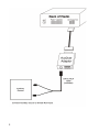
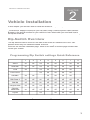
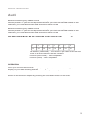
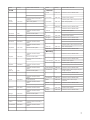
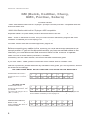
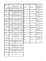
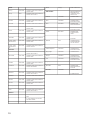
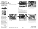
rm11.16.04
Aux2Car
Interface
Instruction Manual
Peripheral Electronics®,
a division of AAMP of America™
13160 56th Court Clearwater, Florida 33760
727-572-9255 or [email protected]
©2005 AAMP™ of Florida, Inc.
Table of Contents
CHAPTER 1
Installation Preparation (All Vehicles)
Pages
1-2
CHAPTER 2
Dip-Switch Overview (REQUIRED)
3
Acura
4
Audi
5
Ford (Ford, Lincoln, Mercury)
6-7
GM (Buick, Cadillac, Chevy, GMC,
Oldsmobile, Pontiac, Saturn)
8-10
Chrysler (Jeep, Dodge, Plymouth, Eagle)
11
Honda
12
Toyota
13
Volkswagen
14
CHAPTER 3
Troubleshooting
15
Warranty/Warnings
16
FCC and Legal Information
17
Ford Appendix
18
GM Appendix 1
19
GM Appendix 2
20
VEHICLE INSTALLATION
Intro
1
CHAPTER
Thank you for purchasing the Aux2Car interface. This interface will allow you
to connect a line level audio input to you vehicle’s factory radio without the
use of a noisy RF modulator. The Aux2Car interface is the best way to add
mobile video, satellite radio, MP3 players or other hand held media devices to
your factory radio.
Installation Preparation
This chapter provides information required for the
installation of the Aux2Car adaptor, it must be read by all users.
Thank you for purchasing the Aux2Car adaptor. Since the Aux2Car
will work in many different vehicles the following steps must be taken
to ensure that it is set up correctly for the vehicle it is being installed in.
Before Installation
To prevent damage to your vehicle and the interface, take the following precautions.
NOTE: If the vehicle is equipped with an on-board drive or navigation computer, do not disconnect the battery cable. If the battery cable is disconnected, the
computer memory may be lost. Under these conditions, use extra caution to avoid causing
a short circuit during installation. If your radio has a security code make sure you know the
code and how to enter it prior to removing the battery cable. The radio will require this code
to operate when the battery terminal is reconnected.
1.
Do not install the unit in the following locations:
A. Locations exposed to direct sunlight
B. Locations where hot air flows from the car’s heater
First Step (For All Vehicles)
The first and most important step in using the Aux2Car is setting the dip-switches on the
interface; this makes the Auxillary source compatible with the vehicle it is being installed in.
The Aux2Car adaptor will not work if this step is not followed correctly.
IMPORTANT!!! Dip Switch settings must be made while unit is unplugged from vehicle. Changes to dip switch settings will not be recognized untill unit is powered down,
then powered up again.
The dip switches can be found on the side of the interface which connects to the source.
Switches are in the “ON” position when they are switched down. Aux2Car settings for each
vehicle can be found on the vehicles installation page. Refer to the index to find the page
number within this manual that covers your vehicle.
1
2
VEHICLE INSTALLATION
2
CHAPTER
Vehicle Installation
In this chapter you will learn how to install the Aux2Car adaptor in specific vehicles.
The Aux2Car adaptor connects to your car radio using a vehicle specific cable harness.
Browse to the specific section for your vehicle to learn what cable you need and how to
set up the Aux2Car and install in your vehicle. Below is an overview of all Aux2Car settings.
Dip-Switch Overview
The dip switches can be found on the side of the Aux2Car. Switches are in the “ON”
position when they are switched DOWN. Aux2Car settings for each vehicle can be
found on the vehicles installation page. Refer to the index to find the page number that
covers your vehicle.
Programming Dip Switch settings Quick Reference
1
2
3
4
5
6
7
8
Acura
on
off
off
on
off
off
off
on
Audi/VW
on
off
off
off
off
off
off
on
Ford
off
on
off
off
off
off
off
on
Ford Focus
on
on
off
off
off
off
off
on
GM E&C
off
off
on
off
off
off
off
on
GM Class 2
on
off
on
off
off
off
off
on
GM XM
off
on
on
off
off
off
off
on
Chrysler new
off
off
off
on
off
off
off
on
Chrysler
old/Honda
on
off
off
on
off
off
off
on
Toyota
on
on
off
on
off
off
off
on
Please consult vehicle specific section for important installation instructions
3
VEHICLE INSTALLATION
Acura
Before connecting any cables to the Aux2Car you must set the dip switches to the
correct position. If you set the dip-switches after you have connected cables to the
interface, you must disconnect and reconnect them for the Aux2Car to operate.
DIP SWITCHES MUST BE SET BEFORE YOU PLUG IN THE Aux2Car !!!
SETTINGS FOR
ALL ACURAS
1
2
3
4
5
6
7
8
on
off
off
on
off
off
off
on
• All Models (1992-2002) – Connector behind the radio, use the
PX HCH2 cable and the Aux2Car settings above.
• TL 1999 to 2002 use Honda cable behind the radio
• Acura NSX, SLX, and MDX (1996 and Up) – Not Compatible.
• Acura’s with navigation are not compatible.
OPERATION
Switch to the Aux2Car adaptor by pressing the CD button on the radio. This step may take
up to three minutes for the radio to initialize. Some radio models require pressing “Seek >”
once to start playing the auxillary source.
4
VEHICLE INSTALLATION
Audi
Before connecting any cables to the Aux2Car you must set the dip switches to the
correct position. If you set the dip-switches after you have connected cables to the
interface, you must disconnect and reconnect them for the Aux2Car to operate.
Before connecting any cables to the Aux2Car you must set the dip switchs to the
correct position. If you set the dip-switches after you have connected cables to the
interface, you must disconnect and reconnect them for the Aux2Car to operate.
DIP SWITCHES MUST BE SET BEFORE YOU PLUG IN THE Aux2Car !!!
1
2
3
4
5
6
7
8
on
off
off
off
off
off
off
on
• All Models (1998-2004) – Pre-wired 13-pin cable in the left-rear
trunk of all Audi vehicles use the PXHAD1
• Audi A8 (2003-2004) – Not Compatible.
• Audi A6 (2004) – Not Compatible.
OPERATION
Once you connect the Aux2Car adaptor, turn on your radio. A CD icon will appear on the
display of your radio showing that the Aux2Car adaptor is ready to use.
Switch to the Aux2Car adaptor by pressing the CD/ Mode button on the radio.
5
VEHICLE INSTALLATION
Ford (Ford, Lincoln, Mercury)
Before connecting any cables to the Aux2Car you must set the dip switches to the
correct position. If you set the dip-switches after you have connected cables to the
interface, you must disconnect and reconnect them for the Aux2Car to operate.
if you use PXHFD1, PXHFD2 make sure that you connect the Black wire to ground and the
Yellow wire to constant 12V+. *If you don’t know the location of constant 12V+, please use a
Volt meter, or consult a Ford dealership.
DIP SWITCHES MUST BE SET BEFORE YOU PLUG IN THE Aux2Car !!!
SETTINGS FOR FORD
FOCUS & COUGAR
SETTINGS FOR ALL
OTHERS
1
2
3
4
5
6
7
8
on
on
off
off
off
off
off
on
1
2
3
4
5
6
7
8
off
on
off
off
off
off
off
on
See the next page for a full list of vehicles as well as plug location in each.
OPERATION
Switch to the Aux2Car adaptor by pressing the “CD” button on the radio.
If you would like to connect Aux2Car adaptor to 2004 - Town Car,
Grand Marquis, Marauder, LS and Ford Crown Victoria, please see
Ford appendix, page 19.
6
Model
Year(s)
IPOD Location and Notes
Ford
1995-1997
Premium Audio System
PXHFD1 (Rear Control Unit) in
the trunk.
Crown
Victoria
Crown
Victoria
Escape
Year(s)
IPOD Location and notes
Aviator
2002-2004
PXHFD3 connector behind Radio.
Continental
1995-1997
Lincoln
PXHFD2 connector behind
Radio.
Crown
Victoria
Model
PXHFD2 connector behind Radio.
PXHFD1 (Rear Control Unit) in the trunk
1995-1997
JBL / Luxury System
Continental
1995-1997
JBL / Luxury System
1998-2003
PXHFD3 connector behind
Radio.
Continental
1998-2004
PXHFD3 connector behind Radio.
LS
2000-2003
PXHFD3 connector behind Radio.
Mark VIII
1995-1998
Navigator
1997-1998
Premium Audio System
Navigator
1999-2004
PXHFD3 connector behind Radio.
Town Car
1995-1997
Town Car
1995-1997
JBL / Luxury System
Town Car
1998-2003
PXHFD3 connector behind Radio.
2001-2004
PXHFD3 connector behind
Radio.
PXHFD2 connector behind
Radio.
Econoline
1997
Premium Audio System
Econoline
1998-2004
PXHFD3connector behind Radio.
Escort
1997-2004
PXHFD2 connector behind
Radio.
Excursion
2000-2004
PXHFD3 connector behind
Radio.
PXHFD2 connector behind
Radio.
Expedition
1997-1998
Premium Audio System
Expedition
1999-2004
PXHFD3 connector behind
Radio.
PXHFD2 connector behind Radio.
1995-1997
PXHFD2 connector behind Radio.
PXHFD1 (Rear Control Unit) in the trunk.
Mercury
Grand Marquis
1995-1997
Grand Marquis
1995-1997
JBL / Luxury System
Grand Marquis
1998-2003
PXHFD3 connector behind Radio.
Mountaineer
1997
PXHFD1 (Rear Control Unit) in rear passenger side panel.
Mountaineer
1997
Premium Audio System
Mountaineer
1998-2004
PXHFD3 connector behind Radio.
6 Disc IPOD only
Sable
1996-2005
PXHFD2 connector behind
Radio.
PXHFD1 (Rear Control Unit) in
trunk/rear.
Tracer
1997-2004
PXHFD2 connector behind Radio.
Villager
1997-1998
Premium Audio System
Villager
1999-2002
PXHFD3 connector behind Radio.
Premium Audio System
1995-1997
JBL / Luxury System
Explorer
1998-2004
PXHFD3 connector behind
Radio.
PXHFD2 connector behind
Radio.
1997
Premium Audio System
1998-2004
PXHFD3 connector behind
Radio.
PXHFD4 connector behind
Radio.
Focus
2000-2003
PXHFD4 connector behind Radio.
1999-2004
Explorer
F-Series
Pick-Up
Premium Audio System
Cougar
PXHFD1 (Rear Control Unit) in
the trunk.
F-150
Pick-Up
Premium Audio System
PXHFD2 connector behind Radio.
PXHFD2 connector behind
Radio.
Explorer
Premium Audio System
HN80 Heavy
Truck
1996-1997
Premium Audio System
Mustang
2001-2004
PXHFD3 connector behind
Radio.
PXHFD2 connector behind
Radio.
Ranger
1995-1997
Premium Audio System
Ranger
1998-2004
PXHFD3connector behind Radio.
Sport Trac
2000-2004
PXHFD3 connector behind
Radio.
Taurus
1996-2005
PXHFD1 (Rear Control Unit) in
the trunk.
Thunderbird
2000-2004
PXHFD3 connector behind
Radio.
Windstar
1999-2004
PXHFD3 connector behind
Radio.
6 Disc IPOD only
PXHFD2 connector behind Radio.
Premium Audio System
PXHFD1 (Rear Control Unit) in the trunk.
PXHFD2 connector behind Radio.
PXHFD2 connector behind Radio.
7
VEHICLE INSTALLATION
GM (Buick, Cadillac, Chevy,
GMC, Pontiac, Saturn)
*PLEASE READ*
*1995-1999 Radios with built in CD player (Except Corvette) are NOT compatible with the
Aux2Car ADAPTER.
*2000-2004 Radios with built in CD player ARE compatible.
Separate OEM CD (1995-2000) must be disconnected to use the Aux2Car adaptor.
2003 – 2005: If XM mode is used, the you must not have GM factory original XM tuner
installed. If installed you must unplug it for Aux2Car adaptor to work.
Corvette: Please see GM-Corvette appendix, page # 20
Before connecting any cables to the Aux2Car you must set the dip switches to the
correct position. If you set the dip-switches after you have connected cables to the
interface, you must disconnect and reconnect them for the Aux2Car to operate.
GM’s use one of three cables (PXHGM1, PXHGM2,
PXHGM3); use the cable that fits, and follow GM table connection guide
If you use “GM-C” cable, please connect the loose Yellow wire to constant 12V+
GM has 3 protocols, please determine by GM table in this guide, your car’s protocol, and set
the Aux2Car accordingly.
DIP SWITCHES MUST BE SET BEFORE YOU PLUG IN THE Aux2Car !!!
SETTINGS FOR CLASS 2
OPERATION FOR CLASS 2
Switch to the Aux2car adaptor by
pressing the “Aux” or “Source”
button.
SETTINGS FOR XM
OPERATION FOR XM
Switch to the Aux2car adaptor by
pressing the “Band” button, until
you see XM1.
The screen will change to D1 T1
( Disc 1, Track 1)
1
2
3
4
5
6
7
8
on
off
on
off
off
off
off
on
1
2
3
4
5
6
7
8
off
on
on
off
off
off
off
on
2003 – 2005: If XM mode is used, the you must not have GM factory original XM
ttuner installed. If installed you must unplug it for Aux2Car adaptor to work.
SETTINGS FOR E & C
OPERATION FOR E&C
1
Switch to the Aux2Car adapoff
tor by pressing the “Aux” or
“Source” button.
8
2
3
4
5
6
7
8
on
on
off
off
off
off
on
Model
Year(s)
Buick
IPOD Location and Notes
Chevrolet - continue
Notes for Buick:Requires GM factory
CD data cable part # 12344003 if not
pre-wired in trunk.
Equinox
2005
PXHGM3 Cable
behind HeadunitProtocol: XM / Class 2
Impala
2000-2005
PXHGM3 Cable
behind HeadunitProtocol: Class 2
Impala
1995-1999
PXHGM1 Cable
behind HeadunitProtocol: E&C
Lumina
1996-1999
PXHGM1 Cable
behind HeadunitProtocol: E&C
Malibu
1997-2000
PXHGM1 Cable
behind HeadunitProtocol: E&C
Monte Carlo
2000-2005
PXHGM3 Cable
behind HeadunitProtocol: Class 2
Monte Carlo
1996-1999
PXHGM1 Cable
behind HeadunitProtocol: E&C
Silverado
2003-2005
PXHGM3 Cable
behind HeadunitProtocol: Class 2
Silverado
1996-2002
PXHGM1 Cable
behind HeadunitProtocol: E&C
Suburban
2003-2005
PXHGM3 Cable
behind HeadunitProtocol: Class 2
Suburban
1995-2002
PXHGM1 Cable
behind HeadunitProtocol: E&C
Tahoe
2003-2005
PXHGM3 Cable
behind HeadunitProtocol: Class 2
Tahoe
1995-2002
PXHGM1 Cable
behind HeadunitProtocol: E&C
Trailblazer
2004
PXHGM3 Cable
behind HeadunitProtocol: XM / Class 2
Venture
2004-2005
PXHGM3 Cable
behind HeadunitProtocol: XM / Class 2
Venture
1997-1999
PXHGM1 Cable
behind HeadunitProtocol: E&C
Century
1997-2003
PXHGM2 Cable in trunk.Protocol: E&C
Le Sabre
2000- 2002
PXHGM2 Cable in trunk.Protocol:
Class 2
Le Sabre
1995-1999
PXHGM2 Cable in trunk.Protocol: E&C
Park Ave
1995-2005
PXHGM2 Cable in trunk.Protocol: E&C
Rainer
2004
PXHGM3 cable behind RadioProtocol:
XM / Class 2
Regal
1995-2003
PXHGM2 Cable in trunk.Protocol: E&C
Riviera
1996-1999
PXHGM2 Cable in trunk.Protocol:
E&C
Rendezvous
2003-2005
PXHGM3 cable behind RadioProtocol:
XM / Class 2
Roadmaster
1995-1996
PXHGM2 Cable in trunk.Protocol: E&C
Skylark
1996-1998
PXHGM2 Cable in trunk.Protocol: E&C
Catera
2000-2001
PXHGM2 Cable in trunk.Protocol:
Class 2
Catera
1997-1999
PXHGM2 Cable in trunk.Protocol: E&C
DeVille
1995-1999
PXHGM2 Cable in trunk.Protocol: E&C
DeVille
2000-2001
PXHGM2 Cable Behind Glove Comp.
Protocol: E&C
DeVille
2001-2005
PXHGM2 Cable Behind Glove Comp.
Protocol: Class 2
Eldorado
1995-2002
PXHGM2 Cable in trunk.Protocol: E&C
Escalade
1999-2002
PXHGM1 Cable behind HeadunitProtocol: E&C
Escalade
2003-2005
PXHGM3 Cable behind HeadunitProtocol: Class 2
Seville
1995-2001
Location: Center Console – PXHGM2
cable; Protocol E&C
Seville
2002-2004
Location: Center Console – PXHGM2
cable; Protocol Class 2
Cadillac
Chevrolet
Astro Van
1996-2005
PXHGM1 Cable behind HeadunitProtocol: E&C
Avalanche
2003-2005
PXHGM3 Cable behind HeadunitProtocol: Class 2
Avalanche
2002
PXHGM1Cable behind HeadunitProtocol: E&C
Blazer
1998-2002
PXHGM1 Cable behind HeadunitProtocol: E&C
Camaro
1997-2002
PXHGM1Cable behind HeadunitProtocol: E&C
AM/FM/Cassette with “TAPE/AUX”
button.
Cavalier
2003-2005
PXHGM3 Cable behind HeadunitProtocol: XM
Cavalier
1996-1999
PXHGM1 Cable behind HeadunitProtocol: E&C
Corvette
1997-2004
PXHGM2 Cable in trunk.Protocol:
E&CIf cable not in trunk, please see
Corvette Notes.
9
GMC
Model
Year(s)
IPOD Location and
Notes
Jimmy
1998-2002
PXHGM1 Cable behind HeadunitProtocol: E&C
Envoy
2004
PXHGM3 Cable behind HeadunitProtocol: XM / Class 2
Envoy
1999-2001
PXHGM1 Cable behind HeadunitProtocol: E&C
Achieva
1996-1998
PXHGM3 Cable in
trunk.Protocol: E&C
Savana
1999-2000
PXHGM1 Cable behind HeadunitProtocol: E&C
Alero
1999-2000
PXHGM2 Cable in
trunk.Protocol: E&C
Sonoma
1998-2002
PXHGM1 Cable behind HeadunitProtocol: E&C
Alero
2003-2004
PXHGM3 Cable
behind HeadunitProtocol: XM
Safari
1996-2005
PXHGM1 Cable behind HeadunitProtocol: E&C
Aurora
1995-1999
PXHGM2 Cable in
trunk.Protocol: E&C
Sierra
1995-2002
PXHGM1 Cable behind HeadunitProtocol: E&C
Aurora
2001-2004
Sierra
2003-2005
PXHGM3 Cable behind HeadunitProtocol: Class 2
PXHGM2 Cable
in trunk.Protocol:
Class 2
Bravada
1997-2001
Suburban
1995-2002
PXHGM1 Cable behind HeadunitProtocol: E&C
PXHGM1Cable
behind HeadunitProtocol: E&C
Yukon; YukonDenali;YukonXL
1995-2002
PXHGM1 Cable behind HeadunitProtocol: E&C
Bravada
2004
PXHGM3Cable behind HeadunitProtocol: XM / Class 2
Yukon; YukonDenali;YukonXL
2003-2005
PXHGM3 Cable behind HeadunitProtocol: Class 2
Cutlass
1997-1999
PXHGM2 Cable in
trunk.Protocol: E&C
Cutlass Supreme
1995-1997
PXHGM2Cable in
trunk.Protocol: E&C
Pontiac
Oldsmobile
Requires GM factory
data cable Part #
12344003 if not prewired in trunk.
Aztek
2003-2005
PXHGM3 Cable behind HeadunitProtocol: XM / Class 2
Eighty-Eight
1996-1999
PXHGM2Cable in
trunk.Protocol: E&C
Bonneville
1996-1999
PXHGM1 Cable behind HeadunitProtocol: E&C
Intrigue
1998-2001
PXHGM2Cable in
trunk.Protocol: E&C
Bonneville
2000-2005
PXHGM2 Cable in trunk.Protocol:
Class 2
LSS
1996-1999
PXHGM2Cable in
trunk.Protocol: E&C
Firebird
1996-2002
PXHGM1 Cable behind HeadunitProtocol: E&C
Regency
1997-1998
PXHGM2Cable in
trunk.Protocol: E&C
Grand Am
2003-2005
PXHGM3 Cable behind HeadunitProtocol: XM /Class 2
Silhouette
2004
PXHGM3 Cable
behind HeadunitProtocol: XM
Grand Am
1996-2000
PXHGM1 Cable behind HeadunitProtocol: E&C
Silhouette
1996-1999
Montana
2004-2005
PXHGM3 Cable behind HeadunitProtocol: XM / Class 2
PXHGM1 Cable behind HeadunitProtocol: E&CRadio must
be AM/FM/CASS.
Montana
1999-2000
PXHGM1 Cable behind HeadunitProtocol: E&C
Sunfire
1996-1999
PXHGM1 Cable behind HeadunitProtocol: E&C
Sunfire
2003-2005
PXHGM3 Cable behind HeadunitProtocol: XM
TransSport
1996-1998
PXHGM1 Cable behind HeadunitProtocol: E&C
Vibe
2004-2005
PXHGM3 Cable behind HeadunitProtocol: XM / Class 2
1995-1999
PXHGM2 Cable in trunk.Protocol:
E&C
Saturn
All Models
2. If not prewired, you must use
two Saturn cables:
GM Part# 21023550 & 21023253
10
VEHICLE INSTALLATION
Chrysler (Chrysler, Jeep, Dodge, Plymouth, Eagle)
Make sure the Aux2Car adaptor is compatible with your vehicle, Check for “Disc ^” printed on
preset button “1”. If you see it, it means that your radio can control the Aux2Car adaptor.
Before connecting any cables to the Aux2Car you must set the dip switches to the
correct position. If you set the dip-switches after you have connected cables to the
interface, you must disconnect and reconnect them for the Aux2Car to operate.
Remove the radio to see which cable fits your vehicle, and then refer to settings below.
Do not force cables in.
DIP SWITCHES MUST BE SET BEFORE YOU PLUG IN THE Aux2Car !!!
SETTINGS FOR
“CHRYSLER OLD
DIN” CABLE
1
2
3
4
5
6
7
8
on
off
off
on
off
off
off
on
Use the PXHCH1 cable with vehicles 1995-1999/2000.
-Connects behind the radio
SETTINGS FOR
“CHRYSLER NEW
DIN” AND “10 PIN
CABLES
OPERATION FOR
ALL
1
2
3
4
5
6
7
8
off
off
off
on
off
off
off
on
Use the PXHCH2 cable with vehicles 1999-2001.
Use the PXHCH3cable with vehicles 2002-2004.
-Connects behind the radio
Switch to the Aux2Car adaptor by pressing the “CD” or
“MODE” button.
11
VEHICLE INSTALLATION
Honda – All Honda except Passport
Before connecting any cables to the Aux2Car you must set the dip switches to the
correct position. If you set the dip-switches after you have connected cables to the
interface, you must disconnect and reconnect them for the Aux2Car to operate.
DIP SWITCHES MUST BE SET BEFORE YOU PLUG IN THE Aux2Car !!!
SETTINGS FOR
HONDA
1
2
3
4
5
6
7
8
off
off
off
on
off
off
off
on
Compatible with Honda 1992- 2004 except:
Honda Passport
2003-2004 Accord ; 2003-2004 Element ; 2004 +
Honda S2000
Honda uses 2 cables:
1992- 1997 – PXHCH2 cable
1998-2004 – PXHHD1 cable
Connects behind the radio
OPERATION
12
Switch to the Aux2car adaptor by pressing the “CD” button.
VEHICLE INSTALLATION
Toyota / Scion / Isuzu / Honda-Passport
Before connecting any cables to the Aux2Car you must set the dip switches to the
correct position. If you set the dip-switches after you have connected cables to the
interface, you must disconnect and reconnect them for the Aux2Car to operate.
DIP SWITCHES MUST BE SET BEFORE YOU PLUG IN THE Aux2Car !!!
SETTINGS FOR
TOYOTA
1
2
3
4
5
6
7
8
on
on
off
on
off
off
off
on
Toyota 1998 – 2005 – Connects behind the radio with
PXHTY1
2003 and newer :4Runner; Sequoia; Rav4; Prius;
Sienna; Tundra; Tacoma; Highlander Must use Toyota
cable adapter, part # 08695-00370
Isuzu 1998-2003 – Connects behind the radio with
PXHTY1
Scion 2003-2005 – Connects behind the radio ( Must
use Toyota cable adapter, part #08695-00370)
Toyota Matrix uses the PXHGM3 cable with GM class
2 settings. Please see GM section.
Cars that need cable part #08695-00370, can only be
purchased from Toyota dealerships.
Call your nearest Toyota dealership, and ask for the
parts dept.
OPERATION
Switch to the Aux2Car adaptor by pressing the “CD” button.
13
TROUBLE SHOOTING
Volkswagen
Make sure you have your radio’s theft protection code before you attempt installation.
When you reconnect power to the battery, you will need to enter this code. Information
about the theft protection code can be found in your vehicle’s audio operation manual.
Before connecting any cables to the Aux2Car you must set the dip switches to the
correct position. If you set the dip-switches after you have connected cables to the
interface, you must disconnect and reconnect them for the Aux2Car to operate.
DIP SWITCHES MUST BE SET BEFORE YOU PLUG IN THE Aux2Car !!!
SETTINGS FOR
ALL VW’S
1
2
3
4
5
6
7
8
on
off
off
off
off
off
off
on
There are two different cables for Volkswagen vehicles. The
PXHVW1 cable is for pre-wired vehicles with the CD Changer
connection in the trunk. The PXHVW2 is for direct connection
behind the radio.
If you use the PXHVW2 cable make sure you connect the black and white cable to ground
If Aux2Car is not being recognized, sound is noisy and/or
Keys on radio not properly working please Disconnect the
Aux2car adapter from trunk, and plug to radio using VW
front cable directly to radio
Cause: VW prewired cable to trunk not shielded and is
causing noise from Aux2Car datalines, into audio lines
OPERATION
14
Switch to the Aux2Car adaptor by pressing the “CD” button on
the radio.
3
TROUBLE SHOOTING
CHAPTER
Symptom
Cause
Remedy
No Power
Blown fuse
Replace fuse with same
amp. Rating. If the fuse
blows again, call tech
support.
No Power
Bad connection
Check cable connection.
Alternator noise is heard
(Changes with gas)
Wrong wiring creates
ground loop.
Call tech support or ask a
local car audio shop.
Radio can’t recognize
Aux2car adaptor
Bad cables or cables are
not connected properly
between converter box and
car radio
Check connection and
cables, push in firmly.
Aux2car adaptor suddenly is
not recognized any more
Bad connection or loss of
power to interface
Unplug the black converter
box from Radio and plug
again
Radio can’t recognize
Aux2car adaptor
Wrong selection on dip
switch in the converter box
Select the right protocol for
you car. (See Page 3)
For technical support call 800-477-2267 9:30 am-6pm EST. MON - FRI
15
Warranty and Warning
One Year Limited Warranty
The quality controls used in the manufacture of this product will ensure your satisfaction.
This warranty applies only to the original purchaser of this product from an authorized
dealer.
This warranty covers any supplied or manufactured parts of this product that, upon inspection by Peripheral Electronics authorized personnel, is found to have failed in normal use
due to defects in material or workmanship. This warranty does not apply to installation
expenses.
Attempting to service or modify this unit, operating this unit under conditions other than
those recommended or voltages other than the voltage indicated on this unit, will render
this WARRANTY VOID.
Unless otherwise prescribed by law, Peripheral Electronics shall not be liable for any personal injury, property damage and or any incidental or consequential damages of any kind
(including water damage) resulting from malfunctions, defects, misuse, improper installation
or alteration of this product.
All parts of this Peripheral Electronics product are guaranteed for a period of 1 year as
follows:
Within the first 12 months from date of purchase, subject to the conditions above, Peripheral Electronics will repair or replace the product at their discretion, if it is defective in material
or workmanship providing it is returned to an Authorized Peripheral Electronics Dealer, with
PROOF OF PURCHASE from an authorized dealer.
Warning:
This equipment may be reset by unintentional electrostatic discharge during operation.
Exposure to direct sunlight or extreme heat may cause damage or malfunction.
16
Caution
1. Use of headphones while operating an automobile or moving vehicle is not recommended and is unlawful in some countries and areas.
2. Be careful and attentive on the road. Stop operation of the Aux2Car adaptor if you find it
disruptive or distracting while driving. The driver of a motor vehicle should not operate the
Aux2Car ADAPTER while driving.
FCC Class B Radio Frequency Interference Statement
This equipment has been tested and found to comply with the limits for a Class B digital
device, pursuant to Part 15 of FCC rules. These limits are designed to provide reasonable protection against harmful interference in a residential installation. This equipment
generates, uses, and can radiate radio frequency energy and, if not installed and used in
accordance with the instructions, may cause harmful interference to radio communications.
However, there is no guarantee that interference will not occur in a particular installation. If
this equipment does cause harmful interference to radio or television reception, which can
be determined by turning the equipment off and on, the user is encourages to try to correct
the interference by one or more of the following measures:
1. Reorient or relocate the receiving antenna.
2. Increase the separation between the equipment and receiver.
3. Connect the equipment into an outlet on a circuit different from that to which
the receiver is connected.
4. Consult the dealer or an experienced radio/television technician for help.
Notice 1: The changes or modifications not expressly approved by the party responsible for
compliance could void the user authority to operate the equipment.
Notice 2: Shielded interface cables, if any, must be used in order to comply with the emission limits.
Copyrights, warnings, and other information.
The illustrations, technical information, data and descriptions contained in this publication
are subject to change without notice.
This publication, together with all information contained in it, and all intellectual property
rights on this publication remain the property of Peripheral Electronics. The user may not
pass this publication on to third parties.
No liability will be accepted for any inaccuracies or omissions in this publication, although
due care has been taken to make it as complete and accurate as possible
17
FORD Appendix
Aux2Car
Car Adaptor Connection
2004 - Town Car, Grand Marquis, Marauder,
LS and Ford Crown Vic.
1. Preparing the Ford-12pin Cable
Take the PXHFD4 cable and cut off the black 12-pin plug. You will use only the cable and
big White 22 pin connector (connects to the iPod2car).
2. Connection to the Vehicle
There are two connectors located behind the radio, a 16 pin connector and a 24 pin connector.
We will first work with the 16 pin connector.
16pin Connector:
Red to 16pin connectors Orange/Black cable (Pin #9)
Blue to 16pin connectors Gray cable (Pin #10)
Green to 16pin connectors Light Green/Red cable (Pin #1)
Pink to 16pin connectors Violet cable (Pin #2)
Yellow to 16pin connectors Light Blue/Pink cable (Pin #7)
White to 16pin connectors Tan cable (Pin #8)
Brown to 16pin connectors Light Green/Black cable (Pin #6)
24pin Connector:
Gray to 24pin connectors Violet/Light Blue cable (Pin #1)
Orange to 24pin connectors Black/Light Green cable (Pin #24)
*Important Note:
Some vehicle production runs do not have a cable plugged into the 16pin pin connector
on the back of the headunit. If you are installing in this type of vehicle you can use another
cable (For example the Honda cable) and shave the plastic off of the white 22pin connector
and remove the pins inside. These pins can then be inserted into the holes on the back of
the vehicles stereo. Call technical support if you need further assistance with this option.
3. Technical Support
If you have any questions or need any support, please feel free to call 800-477-2267 from
9:30am-6pm EST.
18
GM Appendix 1
Corvette
Aux2car Adaptor Connection to
Chevrolet Corvette
Most Corvettes are pre-wired to the trunk. In case you can’t find the connector in the
trunk, please do the following:
1. Preparing the GM-A Cable
Take the PXHGM1 cable and cut off the Black and Red plug. You will then have two cables
in your hands. One cable with the big white 22 pin connector and 1 with a small white 9 pin
connector. You will use only the cable with the big White 22 pin connector (connects to the
Aux2Car).
2. Connection to the Vehicle
There are two connectors located behind the radio, one is black and the other is grey. We
will first work with the grey connector.
Grey Connector:
Blue to Connector Brown+White (Pin 11, the 1st pin)
Red to Connector Green+White (Pin 12, the 2nd pin)
Black to Connector Black+White (Pin 13, the 3rd pin)
Yellow to Connector Dark Green (Pin 15, pin 14 is empty)*
Black Connector:
Orange to Black Connector thick Orange (Pin 10, the last pin, +12v)
Brown to Black Connector Black+White (Pin 5, the middle, Ground)
3. Technical Support
If you have any questions or need any support, please feel free to call 800-477-2267 from
9:30am-6pm EST.
NOTE: CORVETTE 2005 IS NOT COMPATIBLE
19
GM Appendix 2
Cadillac; Oldsmobile; Buick that
use E&C protocol (1995 – 1999 )
- Cable in trunk can’t be found
Most 1995 – 1999 Cadillac’s, Oldsmobile’s & Buick’s are pre-wired to the trunk. In
case you can’t find the connector in the trunk, please do the following:
1. Preparing the PXHGM1 Cable
Take the PXHGM1 cable and cut off the Black and Red plug, you will then have two cables
in your hands. One cable with the big white 22 pin connector and 1 with a small white 9 pin
connector. You will use only the cable with the big White 22 pin connector (connects to the
Aux2Car).
2. Connection to the 32 pin connector behind the Radio
Yellow to 32 pin connector, Pin # 1 DK Green cable ( Data )
* Black to 32 pin connector, Pin # E9 Black +White cable (Audio GND)
* Blue to 32 pin connector, Pin # E10 Brown +White cable (Left Audio)
* Red to 32 pin connector, Pin # E11 DK Green +White cable (Right Audio)
Orange to 32 pin connector, Pin # F1 Orange cable ( 12V+ )
Brown to 32 pin connector, Pin # E16 Black + White cable (Ground)
3. Technical Support
If you have any questions or need any support, please feel free to call 800-477-2267 from
9:30am-6pm EST.
*Some cars don’t have the Brown /White cable to Pin # E10, the Dark Green/White cable to pin #E11 and the Black /White
cable to pin #E9.
In such case, please use from any other cable ( i.e. Ford cable) from the 22pin White connector, the female pin.
Just remove from the white 22 connector a Female pin and use it to connect to GM radio missing pin. It fits perfectly. To
remove pin from 22 pin connector, you can shave of the plastic with a knife until you reach the pin.
20
21
Please check out our other products including:
iPod2car
Interface that connects an iPod to most
factory radios
NeoChanger
Complete universal CD changer that connects to
most factory stereos
Peripheral Electronics®,
a division of AAMP of America™
13160 56th Court Clearwater, Florida 33760
727-572-9255 or [email protected]
©2005 AAMP™ of Florida, Inc.