1
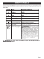
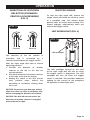
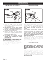
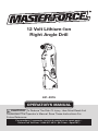
12 Volt Lithium-Ion
Right Angle Drill
241-0315
OPERATOR’S MANUAL
CAUTION: To Reduce The Risk Of Injury, User Must Read And
Understand The Operator’s Manual. Save These Instructions For
Future Reference.
For questions / comments, technical assistance or repair parts –
Please Call Toll Free: 1-866-917-4374. (M-F 8am – 6pm EST.)
table of contents
Safety Symbols. . . . . . . . . . . . . . . . . . . . . . . . . . . . . . . . . . . . . . . . . . . . . . . . . . . . . . . . . . Page 2
Safety Instructions. . . . . . . . . . . . . . . . . . . . . . . . . . . . . . . . . . . . . . . . . . . . . . . . . . . . . . . Page 3
Overview/Specifications . . . . . . . . . . . . . . . . . . . . . . . . . . . . . . . . . . . . . . . . . . . . . . . . . . Page 7
Assembly . . . . . . . . . . . . . . . . . . . . . . . . . . . . . . . . . . . . . . . . . . . . . . . . . . . . . . . . . . . . . . Page 8
Operation . . . . . . . . . . . . . . . . . . . . . . . . . . . . . . . . . . . . . . . . . . . . . . . . . . . . . . . . . . . . . . Page 9
Maintenance. . . . . . . . . . . . . . . . . . . . . . . . . . . . . . . . . . . . . . . . . . . . . . . . . . . . . . . . . . . Page 12
Troubleshooting. . . . . . . . . . . . . . . . . . . . . . . . . . . . . . . . . . . . . . . . . . . . . . . . . . . . . . . . Page 12
Warranty. . . . . . . . . . . . . . . . . . . . . . . . . . . . . . . . . . . . . . . . . . . . . . . . . . . . . . . . . . . . . . Page 14
safety symbols
Some of these following symbols may be used on this tool. Please study them and learn their
meaning. Proper interpretation of these symbols will allow you to operate the tool better and
more safely.
Symbol
Name
Designation / Explanation
V
Volts
Voltage
A
Amperes
Current
Hz
Hertz
Frequency (cycles per second)
W
Watts
Power
∿
Alternating current
Type of current
�
Direct current
Type of characteristic of current
no
No-load speed
Rotational speed at no load
Class II construction
Double insulated construction
Per minute
Revolutions, strokes, surface speed
orbits, etc., per minute
.../min
Wear safety goggles
WARNING: The operation of any
power tool can result in foreign objects
being thrown into your eyes, which can
result in severe eye damage. Before
beginning power tool operation, always
wear safety goggles or safety glasses
with side shields and a full-face shield
when needed. We recommend a Wide
Vision Safety Mask for use over eyeglasses or standard safety glasses with
side shields. Always use eye protection
which is marked to comply with
ANSI Z87.1.
WARNING: To ensure safety and reliability, all repairs should be performed by a
qualified service technician.
Page 2
safety INSTRUCTIONS
The purpose of safety symbols is to attract your attention to possible dangers. The
safety symbols and the explanations with them deserve your careful attention and
understanding. The symbol warnings do not, by themselves, eliminate any danger. The
instructions and warnings they give are no substitutes for proper accident prevention
measures.
WARNING: Be sure to read and understand all safety instructions in this manual,
including all safety alert symbols such as “DANGER,” “WARNING,” and “CAUTION”
before using this tool. Failure to follow all instructions listed below may result in electric
shock, fire, and/or serious personal injury.
SYMBOL MEANING
SAFETY ALERT SYMBOL: Indicates DANGER, WARNING, OR CAUTION.
May be used in conjunction with other symbols or pictographs.
DANGER: Indicates an imminently hazardous situation, which, if not avoided,
will result in death or serious injury.
WARNING: Indicates a potentially hazardous situation, which, if not avoided,
could result in death or serious injury.
CAUTION: Indicates a potentially hazardous situation, which, if not avoided,
could result in minor or moderate injury.
NOTICE: (Without Safety Alert Symbol) Indicates a situation that may result in property
damage.
SAVE THESE INSTRUCTIONS!
Page 3
safety INSTRUCTIONS
GENERAL SAFETY RULES
WARNING: Read all safety
warnings and instructions. Failure to
follow the warnings and instructions may
result in electric shock, fire and/or serious
injury.
Save all warnings and instructions for
future reference.
The term power tool in the warnings
refers to your mains-operated (corded)
power tool or battery-operated (cordless)
power tool.
Work area safety
1. Keep work area clean and well lit.
Cluttered or dark areas invite accidents.
2. Do not operate power tools in
explosive atmospheres, such as in the
presence of flammable liquids, gases or
dust. Power tools create sparks which may
ignite the dust or fumes.
3. Keep children and bystanders away
while operating a power tool. Distractions
can cause you to lose control.
ELECTRICAL SAFETY
1. Power tool plugs must match the
outlet. Never modify the plug in any way.
Do not use any adapter plugs with
earthed
(grounded)
power
tools.
Unmodified plugs and matching outlets
will reduce risk of electric shock.
2. Avoid body contact with earthed or
grounded surfaces such as pipes,
radiators, ranges and refrigerators. There
is an increased risk of electric shock if your
body is earthed or grounded.
3. Do not expose power tools to rain or
wet conditions. Water entering a power
tool will increase the risk of electric shock.
4. Do not abuse the cord. Never use the
cord for carrying, pulling or unplugging
the power tool. Keep cord away from
heat, oil, sharp edges or moving parts.
Damaged or entangled cords increase the
risk of electric shock.
5. When operating a power tool
outdoors, use an extension cord suitable
for outdoor use. Use of a cord suitable
for outdoor use reduces the risk of electric
shock.
6. If operating a power tool in a damp
location is unavoidable, use a ground-fault
circuit interrupter (GFCI) protected supply.
Use of a GFCI reduces the risk of electric
shock.
Personal safety
1. Stay alert, watch what you are doing
and use common sense when operating
a power tool. Do not use tool while tired
or under the influence of drugs, alcohol,
or medication. A moment of inattention
while operating power tools may result
in serious personal injury.
2. Use personal protective equipment.
Always wear eye protection. Protective
equipment such as dust mask, non-skid
safety shoes, hard hat, or hearing protection
used for appropriate conditions will reduce
personal injuries.
3. Prevent unintentional starting. Ensure
the switch is in the off-position before
connecting to power source and/or
battery pack, picking up or carrying the tool.
Carrying power tools with your finger on the
switch or energizing power tools that have
the switch on invites accidents.
4. Remove any adjusting key or wrench
before turning the power tool on. A wrench
or a key left attached to a rotating part of
the power tool may result in personal injury.
5. Do not overreach. Keep proper footing
and balance at all times. This enables
better control of the power tool in
unexpected situations.
Page 4
safety INSTRUCTIONS
6. Dress properly. Do not wear loose
clothing or jewelry. Keep your hair,
clothing and gloves away from moving
parts. Loose clothes, jewelry or long hair
can be caught in moving parts.
7. If devices are provided for the
connection of dust extraction and
collection facilities, ensure these are
connected and properly used. Use of
these devices can reduce dust-related
hazards.
6. Keep cutting tools sharp and clean.
Properly maintained cutting tools with
sharp cutting edges are less likely to bind
and are easier to control.
7. Use the power tool, accessories,
tool bits, etc. in accordance with these
instructions, taking into account the
working conditions and the work to be
performed. Use of the power tool for
operations different from those intended
could result in a hazardous situation.
Power toOl use and care
Battery toOl use and care
1. Do not force the power tool. Use the
correct power tool for your application.
The correct power tool will do the job
better and more safely at the rate for
which it was designed.
2. Do not use the power tool if the
switch does not turn it on and off. Any
power tool that cannot be controlled with
the switch is dangerous and must be
repaired.
3. Disconnect the plug from the power
source and/or the battery pack from
the power tool before making any
adjustments, changing accessories, or
storing power tools. Such preventive
safety measures reduce the risk of starting
the power tool accidentally.
4. Store idle power tools out of the
reach of children and do not allow
persons unfamiliar with the power tool or
these instructions to operate the power
tool. Power tools are dangerous in the
hands of untrained users.
5. Maintain power tools. Check for
misalignment or binding of moving parts,
breakage of parts and any other condition
that may affect the power tool’s operation.
If damaged, have the power tool repaired
before use. Many accidents are caused by
poorly maintained power tools.
1. Recharge only with the charger
specified by the manufacturer. A charger
that is suitable for one type of battery pack
may create a risk of fire when used with
another battery pack.
2. Use power tools only with specifically
designated battery packs. Use of any
other battery packs may create a risk of
injury and fire.
3. When the battery pack is not in use,
keep it away from other metal objects, like
paper clips, coins, keys, nails, screws or
other small metal objects that can make
a connection from one terminal to
another. Shorting the battery terminals
together may cause burns or a fire.
4. Under abusive conditions, liquid may
be ejected from the battery; avoid contact.
If contact accidentally occurs, flush with
water. If liquid contacts eyes, additionally
seek medical help. Liquid ejected from the
battery may cause irritation or burns.
Page 5
Service
1. Have your power tool serviced by
a qualified repair person using only
identical replacement parts. This will
ensure that the safety of the power tool
is maintained.
safety INSTRUCTIONS
SPECIFIC SAFETY
INSTRUCTIONS FOR RIGHT
ANGLE DRILL
1. Use the tool only with the battery
and charger listed below:
Battery pack
Charger
9. Release the trigger immediately when
the screws are tightened to avoid
breaking the screw.
10. For best results, your battery tool
should be charged in a location where
the temperature is more that 50°F (10°C)
but less that 104°F (40°C). Do not store
outside or in vehicles.
252-8016
252-8020
252-8017
2. Hold power tools by their insulated
gripping surfaces when performing an
operation where the cutting tool may
contact hidden wiring or its own cord.
Contact with a “live” wire will make the
exposed metal parts of the tool “live”
and shock the operator.
3. Use clamps or another practical way
to secure and support the workpiece to a
stable platform before drilling. Holding the
work by hand against your body leaves it
unstable and may lead to loss of control.
4. Always hold the tool with both hands.
If the bit jams two hands will give you
maximum control over torque reaction or
kickback.
5. Use protective gloves when removing
the bit from the tool, or first allow the
clamp to cool down. The bit may be hot
after prolonged use.
6. Use protective gloves when operating
the tool. Protective gloves can help to keep
you from being burnt and hurt.
7. Keep your hands away from the
motor-housing vents. Hot gas comes from
the vents during operation.
8. If the bit becomes bound in the
workpiece,
release
the
trigger
immediately, reverse the direction of
rotation and slowly squeeze the trigger
to back out the bit. Be ready for a
strong reaction torque. The drill body will
tend to twist in the opposite direction as
the drill bit is rotating.
Page 6
overview
Hexagonal chuck
Locking sleeve
LED worklight
Direction-of-rotation selector
Variable-speed trigger switch
Specifications
Motor
12 Volt DC
Switch
VSR (Variable Speed Reversible)
No-Load speed
Chuck
Page 7
0-700 RPM
1/4” (6.35 mm)
Maximum torque
120 in-lbs.
Drill weight (Without battery)
1 lb. 6 oz.
Specifications
1/4 in. QUICK CHUCK
LED WORKLIGHT
Quick and easy bit changes without the
need for tools.
The LED worklight, located on the front of
the right angle drill, illuminates when the
trigger switch is depressed. This feature
provides extra light for increased visibility.
VARIABLE SPEED
The variable speed trigger switch delivers
higher speed with increased trigger
pressure and lower speed with decreased
trigger pressure.
FORWARD/CENTER LOCK/REVERSE
ELECTRIC BRAKE
The electric brake will stop the bit rotation
after the operator releases the trigger
switch.
The right angle drill has a direction of
rotation selector for changing the
direction of bit rotation; it is located above
the trigger switch. Setting the trigger switch
in the OFF (center lock) position helps
reduce the possibility of accidental starting
when not in use.
ASSEMBLY
WARNING:
If any part is broken
or missing, do not attempt to attach the
battery or operate the right angle drill until
the broken or missing parts are replaced.
Failure to do so could result in possible
serious injury.
WARNING: Do not attempt to
modify this right angle drill or create
accessories not recommended for use
with this right angle drill. Any such
alteration or modification is misuse and
could result in a hazardous condition
leading to possible serious injury.
WARNING: To prevent accidental
starting that could cause serious personal
injury, always remove the battery pack
from the right angle drill when
assembling parts.
UNPACKING
This product has been shipped completely
assembled.
1. Carefully remove the tool and any
accessories from the box. Make sure
that all items listed in the packing list
are included.
2. Inspect the tool carefully to make sure
no breakage or damage occurred during
shipping.
3.Do not discard the packing material
until you have carefully inspected and
satisfactorily operated the tool.
Contents
Right angle drill, 1pc PH2 bit, nylon storage
bag and operator’s manual.
Page 8
OPERATION
TO ATTACH BATTERY PACK
(Fig. 1)
TO DETACH BATTERY PACK
(FIG. 1)
CAUTION: When placing the
battery pack in the tool, be sure that the
raised rib on battery pack aligns with the
groove on the drill and the latches snap
into place properly. Improper assembly of
the battery pack can cause damage to
internal components.
1.Depress the battery release button
located on the both sides of the battery
pack to release battery pack.
2. Pull battery pack out and remove it from
the tool.
CAUTION: Avoid the possibility of
accidental starting, always take care
not to activate the trigger switch when
you are attaching the battery pack or
performing other adjustments to the tool.
TRIGGER SWITCH (Fig. 2)
FIG. 2
FIG. 1
Variable-speed
trigger switch
Battery release
button
Direction-ofrotation selector
To turn the tool ON, depress the trigger
switch.
To turn it OFF, release the trigger.
VARIABLE SPEED (Fig. 2)
1. Align the raised portion on the battery
pack with the grooves on the bottom of
the right angle drill then attach the
battery pack to the right angle drill as
shown.
2. Make sure that the latch on the battery
pack snaps into place and battery pack
is secured to tool before beginning
operation.
Page 9
The variable-speed trigger switch delivers
higher speed with increased trigger
pressure and lower speed with decreased
trigger pressure.
OPERATION
DIRECTION-OF-ROTATION
SELECTOR (FORWARD/
CENTER LOCK/REVERSE)
(Fig. 3)
FIG. 3
ELECTRIC BRAKE
To stop the right angle drill, release the
trigger switch and allow the chuck to come
to a complete stop. The electric brake
quickly stops the chuck from rotating. This
feature engages automatically when you
release the trigger switch.
LED WORKLIGHT (Fig. 4)
FIG. 4
Forward
Reverse
LED worklight
The direction of the bit rotation is
reversible and is controlled by a
selector located above the trigger switch.
With the right angle drill held in normal
operating position:
1.Position the direction of rotation
selector to the left of the tool for
forward rotation.
2. Position the direction of rotation selector
to the right of the tool for reverse.
3. Setting the switch in the OFF (center
lock) position helps reduce the
possibility of accidental starting when
not in use.
The LED worklight located on the front
of the right angle drill will turn on when
the trigger switch is depressed. The LED
worklight will turn off when the trigger
switch is released. This provides additional
lighting on the surface of the workpiece
for operation in lower light areas.
NOTICE: To prevent gear damage, always
allow the chuck to come to complete stop
before changing the direction of rotation.
NOTICE: The drill will not run unless the
direction of rotation selector is engaged
fully to the left or right.
Page 10
OPERATION
INSTALLING BITS (Fig. 5)
FIG. 5
DRILLING (Fig. 6)
FIG. 6
Chuck
Locking sleeve
1.Lock the trigger switch by placing
the direction of rotation selector in the
OFF (center) position.
2. With one hand, pull the sleeve toward
the front of the tool, and hold it in place.
3. With the other hand, insert the 1/4-in.
bit into the hexagonal chuck.
4. Release the sleeve and check that it
returns to its original position and the
bit is securely held in place.
5.To remove an accessory, pull the
locking sleeve forward and simply
remove the bit.
WARNING: If the sleeve does not
return to its original position, the bit is
not correctly installed. To avoid loss of
control, ensure that the bit is locked in the
chuck by pulling on the bit after it has
been inserted.
When drilling hard, smooth surfaces use
a center punch to mark the desired hole
location. This will prevent the drill bit
from slipping off center as the hole is
started.
The material to be drilled should be
secured in a vise or with clamps to keep
it from turning as the drill bit rotates.
Hold the tool firmly and place the bit at
the point to be drilled. Depress the switch
trigger to start the tool.
Move the drill bit into the workpiece
applying only enough pressure to keep
the bit cutting. Do not force or apply side
pressure to elongate a hole.
DRILLING wood
When drilling hole in wood, twist bits can
be used. Twist bits may overheat unless
pulled out frequently to clear chips from
flutes.
Use a “back-up” block of wood for work that
is likely to splinter, such as thin materials.
You will drill a cleaner hole if you ease up
on the pressure just before the bit breaks
through the wood. Then complete the hole
from the back side.
Page 11
OPERATION
Drilling metal
There are two rules for drilling hard
materials. First, the harder the material,
the greater the pressure you need to
apply to the tool. Second, the harder the
material, the slower the speed you need to
operate the tool.
Here are a few tips for drilling in metal:
2. If the hole to be drilled is fairly large,
drill a smaller hole first, then enlarge
to the required size, it’s often faster in
the long run.
3. Maintain enough pressure to assure
that the bit does not just spin in the
hole. This will dull the bit and greatly
shorten its life.
1. Lubricate the tip of the bit occasionally
with cutting oil except when drilling
soft metals such as aluminum, copper
or cast iron.
maintenance
WARNING: Always wear safety
goggles or safety glasses with side
shields during power tool operation or
when blowing dust. If operation is dusty,
also wear a dust mask.
WARNING: To avoid personal
injury, always remove the battery pack
from the tool when cleaning or performing
any maintenance.
GENERAL MAINTENANCE
Avoid using solvents when cleaning
plastic parts. Most plastics are susceptible
to damage from various types of
commercial
solvents
and
may
be
damaged by their use. Use clean cloths
to remove dirt, dust, oil, grease, etc.
WARNING: Do not at any time let
brake fluids, gasoline, petroleum-based
products, penetrating oils, etc. to come in
contact with plastic parts. Chemicals
can damage, weaken or destroy plastic
which may result in serious personal
injury.
WARNING: When servicing, use
only identical replacement parts. Use of
any other parts may create a hazard or
cause product damage. To ensure safety
and reliability, all repairs should be
performed by a qualified service
technician.
troubleshooting
PROBLEM
CAUSE
SUGGESTED CORRECTIVE ACTION
The drill does not
work.
The battery is depleted.
Charge the battery.
The bit cannot be
installed.
1. The sleeve is not released.
2. Bit does not fit the sleeve.
Use the proper bit.
Page 12
notes
Page 13
12 Volt Lithium-Ion Right Angle Drill
WARRANTY
90-DAY MONEY BACK GUARANTEE:
This MASTERFORCE® brand power tool carries our 90-DAY Money Back
Guarantee. If you are not completely satisfied with your MASTERFORCE® brand
power tool for any reason within ninety (90) days from the date of purchase, return
the tool with your original receipt to any MENARDS® retail store, and we will provide
you a refund – no questions asked.
3-YEAR LIMITED WARRANTY:
This MASTERFORCE® brand power tool carries our famous No Hassle 3-Year
Limited Warranty to the original purchaser.
If, during normal use, this
MASTERFORCE® power tool breaks or fails due to a defect in material or
workmanship within three (3) years from the date of original purchase, simply bring
this tool with the original sales receipt back to your nearest MENARDS® retail store.
At its discretion, MASTERFORCE® agrees to have the tool or any defective part(s)
repaired or replaced with the same or similar MASTERFORCE® product or part
free of charge, within the stated warranty period, when returned by the original
purchaser with original sales receipt. Not withstanding the foregoing, this limited
warranty does not cover any damage that has resulted from abuse or misuse of
the Merchandise. This warranty: (1) excludes expendable parts including but not
limited to blades, brushes, belts, bits, light bulbs, and/or batteries; (2) shall be void
if this tool is used for commercial and/or rental purposes; and (3) does not cover any
losses, injuries to persons/property or costs. This warranty does give you specific
legal rights and you may have other rights, which vary from state to state. Be
careful, tools are dangerous if improperly used or maintained. Seller’s employees
are not qualified to advise you on the use of this Merchandise. Any oral
representation(s) made will not be binding on seller or its employees. The rights
under this limited warranty are to the original purchaser of the Merchandise and may
not be transferred to any subsequent owner. This limited warranty is in lieu of all
warranties, expressed or implied including warranties or merchantability and fitness
for a particular purpose. Seller shall not be liable for any special, incidental, or
consequential damages. The sole exclusive remedy against the seller will be for the
replacement of any defects as provided herein, as long as the seller is willing or
able to replace this product or is willing to refund the purchase price as provided
above. For insurance purposes, seller is not allowed to demonstrate any of these
power tools for you.
For questions / comments, technical assistance or repair parts – Please Call Toll
Free at: 1-866-917-4374. (M-F 8am – 6pm EST)
SAVE YOUR RECEIPTS
THIS WARRANTY IS VOID WITHOUT THEM
Page 14
© 2013 Menard, Inc., Eau Claire, WI 54703
Page 16
09/2013