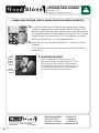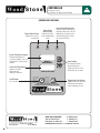
1
Installation and Operation Manual MT. CHUCKANUT MOUNTAIN SERIES Stone Hearth Oven Dual Burner, Gas-Fired Models WS-MS-4-RFG-IR, RFG-IR MT. ADAMS WS-MS-5-RFG-IR, RFG-IR MT. BAKER WS-MS-6-RFG-IR, RFG-IR-(NAP) MT. RAINIER WS-MS-7-RFG-IR, RFG-IR wood stone corporation 1801 w. bakerview rd. bellingham, wa 98226 usa tf.800.988.8103 t.360.650.1111 f.360.650.1166 woodstone-corp.com Revised May 2015 Part no: 9500-0202 Doc no: M0033.03 TABLE OF CONTENTS Mountain Series Installation and Operation Manual TABLE OF CONTENTS MOUNTAIN SERIES���������������������������������������������������������� 3 CAUTIONS AND WARNINGS���������������������������������������������� 4 UNLOADING AND MOVING������������������������������������������������ 6 INSTALLATION CLEARANCES�������������������������������������������� 7 FACADE DETAILS������������������������������������������������������������ 9 OUTDOOR INSTALLATION ���������������������������������������������� 10 GAS SPECIFICATIONS���������������������������������������������������� 11 ELECTRICAL SPECIFICATIONS ���������������������������������������� 13 OVEN VENTING ������������������������������������������������������������ 14 FLUE ADAPTER ������������������������������������������������������������ 17 VENTING DO’S AND DON’TS ������������������������������������������ 18 ASSEMBLY ������������������������������������������������������������������ 26 MANTLE MOUNTING������������������������������������������������������ 27 FRONT PANEL ASSEMBLY���������������������������������������������� 28 EXTENSION PANEL ASSEMBLY���������������������������������������� 29 STUCCO APPLICATION �������������������������������������������������� 31 CONTROLLER �������������������������������������������������������������� 32 INITIAL START-UP �������������������������������������������������������� 33 DAILY OPERATION �������������������������������������������������������� 34 FLAME HEIGHT CONTROL���������������������������������������������� 35 MAINTENANCE ������������������������������������������������������������ 36 PERIODIC THERMAL CLEANING �������������������������������������� 37 TROUBLESHOOTING GUIDE�������������������������������������������� 38 OPERATION SEQUENCE�������������������������������������������������� 39 120 VAC ELECTRICAL DIAGRAM�������������������������������������� 40 240 VAC ELECTRICAL DIAGRAM�������������������������������������� 41 INTERLOCK DIAGRAM���������������������������������������������������� 42 LIMITED WARRANTY������������������������������������������������������ 43 An ongoing program of product improvement may require us to change specifications without notice. WS-MS-(4, 5, 6, 7)-RFG-IR, Revised May 2015. Doc no: M0033.03 2 wood stone corporation 1801 w. bakerview rd. bellingham, wa 98226 usa tf.800.988.8103 t.360.650.1111 f.360.650.1166 [email protected] or visit woodstone-corp.com MOUNTAIN SERIES Mountain Series Installation and Operation Manual INSTALLATION AND OPERATION MANUAL THE WOOD STONE MOUNTAIN SERIES STONE HEARTH COOKING EQUIPMENT WS-MS-(4, 5, 6, 7)-RFG-IR MODELS (INCLUDES MS-6 NAPLES MODEL) GAS-FIRED OVEN ADDITIONAL COPIES AVAILABLE UPON REQUEST An ongoing program of product improvement may require us to change specifications without notice. WS-MS-(4, 5, 6, 7)-RFG-IR, Revised May 2015. Doc no: M0033.03 wood stone corporation 1801 w. bakerview rd. bellingham, wa 98226 usa tf.800.988.8103 t.360.650.1111 f.360.650.1166 [email protected] or visit woodstone-corp.com 3 CAUTIONS AND WARNINGS Mountain Series Installation and Operation Manual WOOD STONE MOUNTAIN SERIES GAS-FIRED OVEN OPERATING INSTRUCTIONS RETAIN THIS MANUAL FOR FUTURE REFERENCE Additional copies of this manual at woodstone-corp.com. For prompt responses to service/maintenance questions, call us at @ 1-800-988-8103. FOR YOUR SAFETY: Consult your local gas supplier for a statement outlining a procedure to be followed in the event you smell gas. Post the statement in a prominent location. READ ALL INSTRUCTIONS BEFORE INSTALLING AND USING THIS APPLIANCE Please read this entire manual before you install the oven. Failure to follow instructions may result in property damage, bodily injury or even death. Contact your local building or fire officials about restrictions and installation inspection in your area. WHEN THE OVEN IS NOT PROPERLY INSTALLED, A FIRE MAY RESULT. TO REDUCE RISK OF FIRE, FOLLOW THE INSTALLATION INSTRUCTION. FOR YOUR SAFETY: Do not store or use gasoline or other flammable vapors or liquids in the vicinity of this or any other appliance. Also, always keep the area under and around this appliance free and clear of any and all combustible materials. IN THE EVENT OF A POWER FAILURE, NO ATTEMPT SHOULD BE MADE TO OPERATE THE OVEN. IMPORTANT: It is recommended that this oven be installed, maintained and serviced by authorized professionals. An ongoing program of product improvement may require us to change specifications without notice. WS-MS-(4, 5, 6, 7)-RFG-IR, Revised May 2015. Doc no: M0033.03 4 wood stone corporation 1801 w. bakerview rd. bellingham, wa 98226 usa tf.800.988.8103 t.360.650.1111 f.360.650.1166 [email protected] or visit woodstone-corp.com CAUTIONS AND WARNINGS Mountain Series Installation and Operation Manual A MAJOR CAUSE OF OVEN RELATED FIRES IS A FAILURE TO MAINTAIN REQUIRED CLEARANCES TO COMBUSTIBLE MATERIAL. IT IS OF UTMOST IMPORTANCE THAT THIS OVEN BE INSTALLED ONLY IN ACCORDANCE WITH THESE INSTRUCTIONS. CAUTION: DISCONNECT POWER TO THE OVEN BEFORE SERVICING OR CLEANING. WARNING: Improper installation, adjustment, alteration, service or maintenance can cause property damage, injury or death. Read the installation, operating and maintenance instructions thoroughly before installing or servicing this equipment. WARNING: This product must be installed by a licensed plumber or gas fitter when installed within the Commonwealth of Massachusetts. SAVE THE INSTRUCTIONS Wood Stone’s gas-fired ovens have been tested and approved by Intertek Testing Services, and are ETL Listed to ANSI Z83.11b - 2009, CSA 1.8b-2009 and to NSF/ANSI Standard 4 - 2009. An ongoing program of product improvement may require us to change specifications without notice. WS-MS-(4, 5, 6, 7)-RFG-IR, Revised May 2015. Doc no: M0033.03 wood stone corporation 1801 w. bakerview rd. bellingham, wa 98226 usa tf.800.988.8103 t.360.650.1111 f.360.650.1166 [email protected] or visit woodstone-corp.com 5 UNLOADING AND MOVING Mountain Series Installation and Operation Manual LIFTING THE OVEN 1. USING A CRANE The oven arrives with four lifting eyes attached. When craning a Wood Stone oven, use a spreader bar with a two-legged sling rigged on each end. The spreader bar should be of a sufficient length to keep the sling from contacting the oven. NOTE: Once lifting eyes are no longer needed, remove the lifting eyes one at a time AND BE SURE TO REPLACE THE BOLTS THAT ATTACH THE OVEN TO THE STAND. 2. USING A FORKLIFT Be sure to use a forklift rated, and forks the minimum length, as shown in the table below. If necessary, fork extensions must be used so the forks extend through the fork lift pockets to the opposite side of the stand. Lift from either side as shown. Do not lift from the front or back. The oven is very top heavy, so spread the forks as far apart as possible. Model WS-MS-4 WS-MS-5 WS-MS-6 WS-MS-7 Oven Mt. Chuckanut Mt. Adams Mt. Baker Mt. Rainier Approximate shipping weight 2,400 lbs. 3,600 lbs. 4,600 lbs. 6,000 lbs. Minimum fork length required 4' 5' 6' 7' Required forklift capacity 5,000 lbs. 6,000 lbs. 6,000 lbs. 9,000 lbs. 3. USING A PALLET JACK Once the oven has been removed from the delivery vehicle, it can easily be moved on flat surfaces using a pallet jack. To lift the oven with a pallet jack, remove the front and rear angle iron stabilizers from the base of the oven stand and place a stout 4x4 post through the fork pocket as shown. THE OVEN IS VERY TOP-HEAVY. MOVING THE OVEN UP OR DOWN A RAMP OR INCLINE ON A PALLET JACK IS NOT SAFE! 4x4 post DO NOT TURN THE OVEN ON ITS SIDE! Contact Wood Stone if the oven must be turned on its side for specific instructions. Moving a Wood Stone oven can present challenges to even the most experienced riggers. Take your time, use your head, secure the proper equipment and make safety your first priority. Please don’t hesitate to call the factory for technical support. DELIVERY NOTE: The customer will receive an Oven Shipping Notification when the oven leaves the Wood Stone factory. This will include a PRO# and a trucking company contact number. Wood Stone recommends that you confirm the delivery date/time with the trucking company before committing to heavy equipment and/or labor. Our goal is a smooth and safe delivery. An ongoing program of product improvement may require us to change specifications without notice. WS-MS-(4, 5, 6, 7)-RFG-IR, Revised May 2015. Doc no: M0033.03 6 wood stone corporation 1801 w. bakerview rd. bellingham, wa 98226 usa tf.800.988.8103 t.360.650.1111 f.360.650.1166 [email protected] or visit woodstone-corp.com INSTALLATION CLEARANCES Mountain Series Installation and Operation Manual CLEARANCES 1. The Wood Stone gas-fired oven must have a minimum 1" clearance to combustibles from all sides, and 14" clearance to combustibles from the top (see INSTALLATION CLEARANCES section on next page). If building a facade that will contact the oven, use completely non-combustible materials*. Please note that standard Drywall (or Sheetrock) is considered a combustible. 2. Any facade materials 6" to either side of the oven doorway and above must be constructed of non-combustible building materials. 3. Install this oven only on a non-combustible floor surface. (Cet appareil doit être installé sur une surface de plancher non-combustible.) The non-combustible floor surface should extend 36" out in front of the oven, and extend 30" to either side of the oven doorway. *When non-combustible building materials contact the body of the appliance, the clearances to combustibles are transferred to those non-combustibles. NOTICE: For stucco-ready appliances (model numbers ending in “-S”), the same clearances as described above apply. Non-combustible stucco mix must be used and applied to a minimum thickness of 1". IF THIS OVEN IS NOT PROPERLY INSTALLED A FIRE MAY RESULT. TO REDUCE THE RISK OF FIRE, FOLLOW THESE INSTALLATION INSTRUCTIONS. A MAJOR CAUSE OF OVEN RELATED FIRES IS FAILURE TO MAINTAIN REQUIRED CLEARANCES (AIR SPACES) TO COMBUSTIBLE MATERIALS. IT IS OF UTMOST IMPORTANCE THAT THIS OVEN BE INSTALLED ONLY IN ACCORDANCE WITH THESE INSTRUCTIONS. WARNING: DO NOT PACK REQUIRED AIR SPACES WITH INSULATION OR OTHER MATERIAL. ! WARNING: Installation and servicing of this product could expose you to glasswool/ceramic fibers as well as calcium silicate dust. ALWAYS WEAR RESPIRATORY AND EYE PROTECTION WHEN INSTALLING OR SERVICING THIS APPLIANCE. Please read this entire manual before you install the oven. Failure to follow instructions may result in property damage, bodily injury or even death. Contact your local building or fire officials about restrictions and installation inspection in your area. PLEASE READ THIS ENTIRE MANUAL BEFORE YOU INSTALL THE OVEN. FAILURE TO FOLLOW INSTRUCTIONS MAY RESULT IN PROPERTY DAMAGE, BODILY INJURY OR EVEN DEATH. CONTACT YOUR LOCAL BUILDING OR FIRE OFFICIALS ABOUT RESTRICTIONS AND INSTALLATION INSPECTION IN YOUR AREA. An ongoing program of product improvement may require us to change specifications without notice. WS-MS-(4, 5, 6, 7)-RFG-IR, Revised May 2015. Doc no: M0033.03 wood stone corporation 1801 w. bakerview rd. bellingham, wa 98226 usa tf.800.988.8103 t.360.650.1111 f.360.650.1166 [email protected] or visit woodstone-corp.com 7 INSTALLATION CLEARANCES Mountain Series Installation and Operation Manual THE FOLLOWING CLEARANCE INFORMATION APPLIES TO ALL WOOD STONE MOUNTAIN SERIES OVENS 14" top clearance to combustible building materials. 14" Any facade materials 6" to either side of the doorway and above must be NONCOMBUSTIBLE. 1" side clearance to combustible building materials. Note: 0" side and top clearance to noncombustible materials. However, the respective clearances to combustibles are transferred to those noncombustibles. For use only on noncombustible floors (installér sur un plancher incombustible seulement). Non-combustible floor surface AND provided with a noncombustible floor covering at least 30" to each side of, and 36" in front of the door opening. Combustible building material Non-combustible building material Any facade wall 6" to either side of the oven doorway and above MUST be of non-combustible construction with no exceptions. An ongoing program of product improvement may require us to change specifications without notice. WS-MS-(4, 5, 6, 7)-RFG-IR, Revised May 2015. Doc no: M0033.03 8 wood stone corporation 1801 w. bakerview rd. bellingham, wa 98226 usa tf.800.988.8103 t.360.650.1111 f.360.650.1166 [email protected] or visit woodstone-corp.com FACADE DETAILS Mountain Series Installation and Operation Manual Wood Stone Mountain Series (MS-) ovens carry an ETL Sanitation listing. The oven interior only is ETL listed to NSF/ ANSI Standard 4. This means that the surfaces of the oven which are meant to be left exposed after the facade has been put in place have been evaluated from the standpoint of sanitation and food safety and found to comply with NSF/ ANSI Standard 4. To operate the oven in accordance with NSF/ANSI Standard 4, only pizza and bread products may be cooked directly on the floor of the oven. Other types of food may be cooked on or in pans, or other suitable containers to prevent spillage onto the oven deck. Go to www.woodstone-corp.com for detailed instructions for constructing a facade around a Wood Stone oven. If using an exhaust hood over the oven, make sure your facade allows proper access for removal of the hood filters. A removable Service Panel or storage box allows access for service of gas and electrical components. If this panel is not used, access and air intake of equivalent dimensions MUST be provided at the front of the oven. Hatched areas shall not be exposed after installation of facade. Any facade wall 6" to either side of the oven doorway and above MUST be of non-combustible construction with no exceptions. An ongoing program of product improvement may require us to change specifications without notice. WS-MS-(4, 5, 6, 7)-RFG-IR, Revised May 2015. Doc no: M0033.03 wood stone corporation 1801 w. bakerview rd. bellingham, wa 98226 usa tf.800.988.8103 t.360.650.1111 f.360.650.1166 [email protected] or visit woodstone-corp.com 9 OUTDOOR INSTALLATION Mountain Series Installation and Operation Manual OUTDOOR INSTALLATIONS The Mountain Series (MS-) model ovens are ETL approved for outdoor installation. When installed outdoors, the open area beneath the oven must be enclosed, with the exception of the perforated area on the front Service Panel (or storage box) for air intake. The oven may be installed in a weatherproof enclosure. If so be sure to maintain all clearances and adhere to the installation requirements included in this manual. KEEP THE AREA AROUND AND BENEATH THE OVEN CLEAR OF GRASS, LEAVES AND OTHER COMBUSTIBLE MATERIALS. Wood Stone also offers the following options to enclose the area beneath the oven Lower Lagging Kit Stand Wrap Kit An ongoing program of product improvement may require us to change specifications without notice. WS-MS-(4, 5, 6, 7)-RFG-IR, Revised May 2015. Doc no: M0033.03 10 wood stone corporation 1801 w. bakerview rd. bellingham, wa 98226 usa tf.800.988.8103 t.360.650.1111 f.360.650.1166 [email protected] or visit woodstone-corp.com GAS SPECIFICATIONS Mountain Series Installation and Operation Manual The Wood Stone Gas ovens are equipped with a 3/4" NPT gas connection located at the rear left of the oven. Have a licensed gas installer provide the hook-up and test all fittings and pipe connections for leaks. Use approved gas leak detectors (soap solutions or equivalent) over and around the fittings and pipe connections. DO NOT USE FLAME TO TEST FOR LEAKS! SV-1 is the gas control valve that operates the Underfloor Infrared (IR) burner. The manifold pressure test port is 1/8: NPT pugged tap located on the IR burner manifold. SV-2 is the gas control valve that operates the interior radiant burner. SV-2 is located at the rear left beneath the oven. The manifold pressure test port for the radiant burner is a 1/8" NPT plugged tap located at the base of the T-junction between the SV-2 and the radiant/interior burner. NOTE: Gas valves are shipped in the ON position. The burner manifold pressure has been adjusted and tested at the factory. A variety of factors can influence this pressure, so be sure to test the burner manifold pressure and adjust the valve as necessary to achieve the specified pressure. NOTE: Maximum inlet gas pressure: 1/2 psi (14 inches W.C.) This oven requires no modifications or adjustments for use at high altitudes. Factory specified individual burner manifold pressures (W.C.) for RFG-IR models equipped to burn Natural Gas (NG) Model WS-MS-4-RFG-IR-NG WS-MS-5-RFG-IR-NG WS-MS-6-RFG-IR-NG WS-MS-7-RFG-IR-NG SV-1 SV-2 3.5" 3.5" 3.5" 3.5" 5" 4.75" 4.75" 4.6" Factory specified individual burner manifold pressures (W.C.) for RFG-IR models equipped to burn Propane (LP & HLP) Model WS-MS-4-RFG-IR-LP WS-MS-5-RFG-IR-LP WS-MS-6-RFG-IR-LP WS-MS-7-RFG-IR-LP SV-1 SV-2 9" 9" 9" 9.2" 7" 8" 8" 9.5" An ongoing program of product improvement may require us to change specifications without notice. WS-MS-(4, 5, 6, 7)-RFG-IR, Revised May 2015. Doc no: M0033.03 Model WS-MS-4-RFG-IR-HLP WS-MS-5-RFG-IR-HLP WS-MS-6-RFG-IR-HLP WS-MS-7-RFG-IR-HLP wood stone corporation 1801 w. bakerview rd. bellingham, wa 98226 usa SV-1 SV-2 9" 9" 9" 9.2" 7" 8" 8" 9.5" tf.800.988.8103 t.360.650.1111 f.360.650.1166 [email protected] or visit woodstone-corp.com 11 GAS SPECIFICATIONS Mountain Series Installation and Operation Manual Hourly Natural Gas (NG) BTU/hr input rates for Wood Stone RFG-IR models Model WS-MS-4-RFG-IR-NG WS-MS-5-RFG-IR-NG WS-MS-6-RFG-IR-NG WS-MS-6-RFG-IR-NAP-NG WS-MS-7-RFG-IR-NG BTU/hr Input Rate 125,000 188,000 188,000 218,330 220,000 Note: For MS-4, 5, 7-RFG-IR-NAP-NG models there is no change in BTU/hr. Hourly Propane (LP & HLP) BTU/hr input rates for Wood Stone RFG-IR models Model WS-MS-4-RFG-IR-LP WS-MS-5-RFG-IR-LP WS-MS-6-RFG-IR-LP WS-MS-6-RFG-IR-NAP-LP WS-MS-7-RFG-IR-LP BTU/hr Input Rate 110,000 159,000 159,000 218,330 227,000 Model WS-MS-4-RFG-IR-HLP BTU/hr Input Rate WS-MS-5-RFG-IR-HLP WS-MS-6-RFG-IR-HLP WS-MS-6-RFG-IR-NAP-HLP WS-MS-7-RFG-IR-HLP 125,000 188,000 188,000 218,330 227,000 Note: For MS-4, 5, 7-RFG-IR-NAP-LP models there is no change in BTU/hr. Wood Stone recommends that the appliance’s individual shutoff valve (supplied by others) be left readily accessible. Wood Stone also recommends that inspection and maintenance of the burners and gas piping connections of this appliance be performed at regularly scheduled intervals and only by professional gas appliance service agencies. GAS CODE LIMITATIONS The installation of this appliance must conform with local codes, or in the absence of local codes, with the National Fuel Gas Code, ANSI Z223.1 or The Natural Gas installation Code CAN/CGA-B149.1 as applicable, including: The appliance and its individual shutoff valve (supplied by others) must be disconnected from the gas supply piping system during any pressure testing of that system at test pressures in excess of 1/2 psi (3.45 kPa). The appliance must be isolated from the gas supply piping system by closing its individual manual shutoff valve (supplied by others) during any pressure testing of the gas supply piping system at test pressure, equal to or less than 1/2 psi (3.45 kPa). An ongoing program of product improvement may require us to change specifications without notice. WS-MS-(4, 5, 6, 7)-RFG-IR, Revised May 2015. Doc no: M0033.03 12 wood stone corporation 1801 w. bakerview rd. bellingham, wa 98226 usa tf.800.988.8103 t.360.650.1111 f.360.650.1166 [email protected] or visit woodstone-corp.com ELECTRICAL SPECIFICATIONS Mountain Series Installation and Operation Manual Incoming power should be connected to the terminal strip located in the Transformer Junction Box beneath the oven (see diagram below). The standard oven model comes configured for connection to a 120 VAC circuit. The oven can be ordered configured for connection to a 240 VAC circuit. Always refer to the equipment data plate beneath the oven to verify the proper voltage. The voltage is also specified on the transformer box cover. Never connect an oven rated 120 VAC to a 240 VAC circuit or vice versa. It is recommended that the oven be connected to its own individual branch circuit. Have a licensed electrician connect the oven to the appropriate 120 VAC or 240 VAC circuit. Electrical diagrams are located directly to the right, behind the removable service/intake panel of the appliance as well as inside the control box. Electrical diagrams are also located near the end of this manual. See the FRONT PANEL ASSEMBLY section of this manual for the location of the transformer housing. ELECTRICAL RATINGS 120 VAC, 1.1A, 50/60 Hz 240 VAC, 1.1A, 50/60 Hz ELECTRICAL CODE LIMITATIONS Electrical Grounding: This appliance must be electrically grounded in accordance with local codes, or in the absence of local codes, with the National Electrical code, ANSI/NFPA 70 or the Canadian Electrical Code, CSA C22.1 as applicable. Terminal Strip location An ongoing program of product improvement may require us to change specifications without notice. WS-MS-(4, 5, 6, 7)-RFG-IR, Revised May 2015. Doc no: M0033.03 wood stone corporation 1801 w. bakerview rd. bellingham, wa 98226 usa tf.800.988.8103 t.360.650.1111 f.360.650.1166 [email protected] or visit woodstone-corp.com 13 VENTING Mountain Series Installation and Operation Manual The following are the manufacturer’s recommendations for venting the Wood Stone MS (Mountain Series) RFG-IR ovens. It is never appropriate to use “B vent” in any part of an exhaust system connected to a Wood Stone oven. All duct material must be manufactured to the specifications of a grease duct. Submit your venting plans to your local authorities before proceeding with your installation, as there may be additional requirements in your area. All non-solid fuel venting systems should be inspected and cleaned at least every 3 months. There are three venting options. VENTING OPTION 1 Direct Connection: A Listed building heating appliance chimney, also listed as a grease duct as described in NFPA 96, connected directly to the oven flue collar and provided with a power ventilator listed for restaurant appliance exhaust. The power ventilator should be rated for a minimum of 300 °F. Wood Stone does not recommend the use of an in-line fan. A field built grease duct, constructed and installed to the specifications of a grease duct as detailed in NFPA 96 or the International Mechanical Code, may also be used. A static pressure of -0.1 inches water column is necessary at the oven flue collar to ensure that flue gas temperatures do not exceed 300 °F at the fan inlet. This measurement may be taken by inserting the probe of the magnahelic gauge through the oven doorway, upwards to the oven flue collar. NOTE: Double door ovens (models ending in “-DD”), have two flue collars. Both must be connected and a static pressure of negative 0.1 inches must be maintained at each collar. See table below for CFM required to attain the specified static pressure. CFM REQUIREMENTS Model CFM required WS-MS-4-RFG-IR WS-MS-5-RFG-IR WS-MS-6-RFG-IR WS-MS-7-RFG-IR 400 450 450 450 Install the venting system in accordance with the duct manufacturer’s instructions and in accordance with all local codes. All field built components should be built to the applicable codes and standards and are subject to the approval of the authority having jurisdiction. NOTE: If your MS-5, MS-6 or MS-7 oven is ordered from Wood Stone without a hood, it will have a round flue adapter installed to facilitate direct connection to a round duct. If the oven is to be installed under a hood, it MAY be necessary to remove the round adapter to properly position the hood. This is done by removing the screws that attach the adapter to the oven. Please contact Wood Stone if you have any questions. Collar I.D. Model WS-MS-5 WS-MS-6 WS-MS-7 Flue adapter An ongoing program of product improvement may require us to change specifications without notice. WS-MS-(4, 5, 6, 7)-RFG-IR, Revised May 2015. Doc no: M0033.03 14 Oven Flue Collar I.D. (nominal) Mt. Adams Mt. Baker Mt. Rainier 10 inch 10 inch 10 inch NOTE: MS-4 ovens come standard with a round 8" O.D. collar and do not require the flue adapter for a direct connection. wood stone corporation 1801 w. bakerview rd. bellingham, wa 98226 usa tf.800.988.8103 t.360.650.1111 f.360.650.1166 [email protected] or visit woodstone-corp.com OVEN VENTING Mountain Series Installation and Operation Manual INSTALLATION VIEWS OF A WOOD STONE HOOD Flat face hood Curved face hood Allow sufficient opening between any facade and the inside edge of the front of the hood to allow for filter removal and hood cleaning. Any front facade wall should not be built any higher than the top of the oven to allow for access to the filter. VENTING OPTION 2 A Listed Type 1 exhaust hood or one that is constructed and installed in accordance with all relevant Local and National Codes. Wood Stone offers eyebrow-type hoods designed specifically for Wood Stone ovens. See specification sheet on ventilators for Wood Stone ovens. Note that the notch of the hood is even with the front edge of the oven. The hood must be installed in accordance with the hood manufacturer’s instructions, and with the Standard for Ventilation Control and Fire Protection of Commercial Cooking Operations, NFPA 96 and/or the applicable local and national codes. Refer to the exhaust hood manufacturer’s recommendations for inspection, maintenance and cleaning. VENTING OPTION 3 Exhaust from Wood Stone gas-fired ovens (RFG-IR models) can be vented using one of the previously mentioned methods OR, when vented with a hood, can be combined with exhaust from other equipment, assuming the common duct meets the construction requirements listed in Option 1. The system must be properly engineered to provide proper airflow to hood serving the oven. It is never appropriate to use “B vent” in any part of an exhaust system connected to a Wood Stone oven. All duct material must be manufactured to the specifications of a grease duct. Due to the possibility of sparks entering the duct, exhaust systems serving solid fuel equipment MUST NOT be combined with exhaust systems serving other (nonsolid fuel) equipment. VERY IMPORTANT! WOOD STONE RECOMMENDS THAT YOU CONSULT WITH A QUALIFIED MECHANICAL ENGINEER AND SUBMIT YOUR VENTING PLANS TO LOCAL CODE AUTHORITIES BEFORE PROCEEDING WITH INSTALLATION. An ongoing program of product improvement may require us to change specifications without notice. WS-MS-(4, 5, 6, 7)-RFG-IR, Revised May 2015. Doc no: M0033.03 wood stone corporation 1801 w. bakerview rd. bellingham, wa 98226 usa tf.800.988.8103 t.360.650.1111 f.360.650.1166 [email protected] or visit woodstone-corp.com 15 OVEN VENTING Mountain Series Installation and Operation Manual FIRE SUPPRESSION Check with your local code officials to see if fire suppression is required in your area. If fire suppression is required, you must vent the oven using a Type 1 hood constructed and installed in accordance with NFPA 96. If fire suppression is required, Wood Stone recommends providing protection for the hood duct collar and plenum. The fusible link in the hood must be rated at 450 °F minimum. Wood Stone offers Listed exhaust hoods for our ovens that are pre-piped for ANSUL R-102 fire suppression. Wood Stone does not recommend aiming any fire suppression nozzles into the cooking chamber of the oven. All installations are subject to the approval of the local authority having jurisdiction. An ongoing program of product improvement may require us to change specifications without notice. WS-MS-(4, 5, 6, 7)-RFG-IR, Revised May 2015. Doc no: M0033.03 16 wood stone corporation 1801 w. bakerview rd. bellingham, wa 98226 usa tf.800.988.8103 t.360.650.1111 f.360.650.1166 [email protected] or visit woodstone-corp.com FLUE ADAPTER Mountain Series Installation and Operation Manual MOUNTAIN SERIES OVENS: FLUE ADAPTER The flue adapter unit is designed to facilitate connection to a round duct. Use the stainless steel screws and sealant provided to attach the flue adapter to the exhaust outlet on the oven if it is not already installed. NOTE: MS-4 ovens come standard with a round 8" O.D. collar and do not require the flue adapter for a direct connection. Note: If using a Selkirk or other modular-type duct, attach according to the manufacturer’s instructions. Otherwise, the duct must be attached with a full perimeter weld. All duct must be grease-rated duct. If the oven is going to be enclosed, the flue adapter and exhaust outlet must be wrapped with an insulating material approved for use with a grease-duct. Flue adapter Flue adapter attached to oven flue collar If the oven is to be enclosed, wrap with an approved insulation. An ongoing program of product improvement may require us to change specifications without notice. WS-MS-(4, 5, 6, 7)-RFG-IR, Revised May 2015. Doc no: M0033.03 wood stone corporation 1801 w. bakerview rd. bellingham, wa 98226 usa tf.800.988.8103 t.360.650.1111 f.360.650.1166 [email protected] or visit woodstone-corp.com 17 VENTING DO’S AND DON’TS Mountain Series Installation and Operation Manual VENTING DO’S AND DON’TS When installing a Wood Stone Mountain Series oven there are some basic guidelines to follow regarding oven venting that will help ensure proper operation and performance of the gas burners on the oven. These guidelines will also help prevent damage to the oven's gas and electrical components due to improper venting and installation. Damage caused by improper venting and installation is not covered by the oven warranty. This information applies to all Wood Stone Mountain Series (MS) ovens equipped with one or more gas burners. Most Wood Stone Mountain Series ovens are built into some sort of wall structure or enclosure. This creates the potential for different venting scenarios that can be detrimental to the operation and performance of the oven burners. Here are some basic rules that to follow that will ensure a properly functioning oven installation. Illustrated examples are included on the following pages. RULE 1 The ONLY pathway for air to enter the space beneath the oven should be at the front of the oven at the perforated opening in the oven Service Panel provided with the oven, or on ovens equipped with an optional Storage Box, through the perforations provided on the oven Storage Box. This will eliminate the chance of air movement or cross drafts beneath the oven that can disrupt the oven burners. RULE 2 DO NOT block the flow of air through the front Service Panel. It is required to provide necessary combustion air to the oven burners. Airflow and service access MUST be provided from the front of the oven only at this Service Panel. DO NOT relocate the oven air intake (see Rule 1). RULE 3 To ensure proper venting of the oven, you must use an appropriate exhaust fan as described in this manual. There must also be an adequate source of make-up air provided to your kitchen space—the room that the oven opens into. The make-up air supply should not point directly at the oven. Other than the oven Service Panel, do not provide make-up air or other ventilation into an enclosure that surrounds the oven (see Rule 1). Without proper make-up air the oven, (or any gas equipment), will not vent and operate correctly. Please review the illustrations on the following pages. An ongoing program of product improvement may require us to change specifications without notice. WS-MS-(4, 5, 6, 7)-RFG-IR, Revised May 2015. Doc no: M0033.03 18 wood stone corporation 1801 w. bakerview rd. bellingham, wa 98226 usa tf.800.988.8103 t.360.650.1111 f.360.650.1166 [email protected] or visit woodstone-corp.com VENTING DO’S AND DON’TS Mountain Series Installation and Operation Manual DIRECT CONNECT VENTING EXAMPLES Equal air pressure inside and outside of oven room Stud wall Facade surface Air intake area on removable Service Panel properly exposed Exhaust flow direction is normal Example 1 shows a proper installation. The enclosure around the oven is completely sealed so that the only air entering the space beneath the oven comes through the oven Service Panel. Intake air flows through designed intake vents in the Service Panel to oven burners 1 Acceptable venting Equal air pressure inside and outside of oven room Facade material improperly placed over oven air intake Exhaust flow direction is normal Example 2 is not acceptable because the combustion air intake is blocked, preventing combustion air from reaching the oven burners. The burners will not function properly, and will lead to damage of oven components. Insufficient combustion air resulting in burner problems & poor oven performance 2. Unacceptable venting An ongoing program of product improvement may require us to change specifications without notice. WS-MS-(4, 5, 6, 7)-RFG-IR, Revised May 2015. Doc no: M0033.03 wood stone corporation 1801 w. bakerview rd. bellingham, wa 98226 usa tf.800.988.8103 t.360.650.1111 f.360.650.1166 [email protected] or visit woodstone-corp.com 19 VENTING DO’S AND DON’TS Mountain Series Installation and Operation Manual DIRECT CONNECT VENTING EXAMPLES Neutral room air pressure Equal air pressure inside and outside of oven room Low pressure is created by HVAC or any air moving equipment outside the oven room Exhaust flow direction is reversed Exhaust air is pulled backwards through oven burners An added vent intended to increase air supply Airflow to oven is altered as air moves from normal to low pressure Example 3 shows an incorrect installation where an additional vent was added to the wall behind the oven, creating an air pressure difference causing air movement beneath the oven and disrupting the operation of the oven burners. This air movement can be so severe as to cause a downdraft, pulling the exhaust down the oven flue and backwards through the burners, leading to heat damage of oven components. 3. Unacceptable venting Low pressure area Air flow False ceiling Exhaust flow direction is reversed Combustion air is diverted from oven burners because room is open to a low pressure area. Exhaust air is pulled backwards through oven burners. Example 4 shows an incorrect installation where the enclosure surrounding the oven is open to the attic space above the ceiling. Air can move rapidly through the space enclosing the oven to the lower pressure area within the attic space. This can cause a downdraft situation at the oven, pulling air and heat backwards through the oven burners, leading to damage of oven components. 4. Unacceptable venting An ongoing program of product improvement may require us to change specifications without notice. WS-MS-(4, 5, 6, 7)-RFG-IR, Revised May 2015. Doc no: M0033.03 20 wood stone corporation 1801 w. bakerview rd. bellingham, wa 98226 usa tf.800.988.8103 t.360.650.1111 f.360.650.1166 [email protected] or visit woodstone-corp.com VENTING DO’S AND DON’TS Mountain Series Installation and Operation Manual DIRECT CONNECT VENTING EXAMPLES Low pressure area Air flow Equal air pressure inside and outside of oven room Exhaust flow direction is nomal False ceiling Addition of an oven room ceiling isolates the oven from low pressure areas thus equalizing air pressure and allowing normal airflow to the oven burners. Example 5 shows a correct installation where a ceiling has been added to the enclosure surrounding the oven to correct an improper installation. 5 Acceptable venting An ongoing program of product improvement may require us to change specifications without notice. WS-MS-(4, 5, 6, 7)-RFG-IR, Revised May 2015. Doc no: M0033.03 wood stone corporation 1801 w. bakerview rd. bellingham, wa 98226 usa tf.800.988.8103 t.360.650.1111 f.360.650.1166 [email protected] or visit woodstone-corp.com 21 VENTING DO’S AND DON’TS Mountain Series Installation and Operation Manual HOOD INSTALLATIONS In addition to the information given for installations using the direct connect venting method, the following information applies to installations where the oven is being vented using a Listed Type 1 hood. Also refer to the OVEN VENTING section earlier in this manual. PROPER MOUNTING POSITION FOR THE WOOD STONE HOOD 1. Center the hood from side to side on the oven (A). Note that in an MS-5, 6 or 7 model, the oven may have the round flue adapter attached. The adapter can prevent the proper positioning of the hood. The flue adapter is attached with screws. Simply remove the screws to remove the adapter if it is in the way. 2. Pull the hood forward so that the notch (B), as viewed from the side of the hood, lines up with the front edge of the top of the oven. 3. Secure the hood to the top of the oven using #10 self-tapping screws. The flanges on the hood are pre-drilled (C). Screw directly into the top of the oven to secure the hood. 4. Attach grease-rated duct to the outlet on the hood. The hood captures over the oven flue collar and oven doorway. No connection is made to the oven flue collar. An ongoing program of product improvement may require us to change specifications without notice. WS-MS-(4, 5, 6, 7)-RFG-IR, Revised May 2015. Doc no: M0033.03 22 wood stone corporation 1801 w. bakerview rd. bellingham, wa 98226 usa tf.800.988.8103 t.360.650.1111 f.360.650.1166 [email protected] or visit woodstone-corp.com VENTING DO’S AND DON’TS Mountain Series Installation and Operation Manual HOOD INSTALLATION WITH DECORATIVE FACADE WALL/OVEN ENCLOSURE For installations where a hood is being used with a decorative facade wall or oven enclosure, it will be necessary to both seal the gap between the facade wall and the top of the oven, and the gaps at the sides of the hood between the facade wall and the front of the oven. This will prevent air from being pulled up the sides of the oven from below by the hood. It will also prevent debris, etc. from falling into the facade wall. Flashing piece by installer Acceptable venting Additional flashing detail Wall stud Shield flashing to be flush with top of oven Note that the hood extends out beyond the face of the oven. DO NOT extend the oven facade wall into the oven hood. The wall beneath the hood must stop at the top of the oven. To allow for proper function of the hood, filter removal and hood maintenance, you must provide a minimum of 8 inches of clearance between the front face of the facade wall and the front of the hood. Acceptable venting An ongoing program of product improvement may require us to change specifications without notice. WS-MS-(4, 5, 6, 7)-RFG-IR, Revised May 2015. Doc no: M0033.03 wood stone corporation 1801 w. bakerview rd. bellingham, wa 98226 usa tf.800.988.8103 t.360.650.1111 f.360.650.1166 [email protected] or visit woodstone-corp.com 23 VENTING DO’S AND DON’TS Mountain Series Installation and Operation Manual Incorrect installation. No flashing has been installed so air being pulled up the sides of the oven from beneath. Unacceptable venting Exhaust stack Stud wall Side view of properly installed hood Hood Airflow shield Facade surface Acceptable venting An ongoing program of product improvement may require us to change specifications without notice. WS-MS-(4, 5, 6, 7)-RFG-IR, Revised May 2015. Doc no: M0033.03 24 wood stone corporation 1801 w. bakerview rd. bellingham, wa 98226 usa tf.800.988.8103 t.360.650.1111 f.360.650.1166 [email protected] or visit woodstone-corp.com VENTING DO’S AND DON’TS Mountain Series Installation and Operation Manual CLEARANCES The Type 1 hood requires an 18-inch clearance to combustible construction. Clearances to limited combustibles may be reduced per NFPA 96 and/or your local codes. Approved clearance reduction methods may also be used, per NFPA 96 and/or your local codes. (These reductions are applicable to the hood and/or duct only, NOT to the oven.) Consult with your local inspector regarding approved methods. Any facade wall 6" to either side of the oven doorway and above MUST be of non-combustible construction with no exceptions. Shaded areas must be of non-combustible construction. Maintain 18" clearance to combustible construction from hood. Clearance reduction methods described in NFPA 96 may be used subject to the approval of the authority having jurisdiction. Any facade wall six inches from either side of the doorway and above (as shown in green) must be of noncombustible construction. All installations subject to the approval of the local authority having jurisdiction. Wood Stone recommends you submit your venting plans in advance to your local authority for approval. An ongoing program of product improvement may require us to change specifications without notice. WS-MS-(4, 5, 6, 7)-RFG-IR, Revised May 2015. Doc no: M0033.03 wood stone corporation 1801 w. bakerview rd. bellingham, wa 98226 usa tf.800.988.8103 t.360.650.1111 f.360.650.1166 [email protected] or visit woodstone-corp.com 25 ASSEMBLY Mountain Series Installation and Operation Manual 1. Mount the oven mantle (if provided) using the hardware provided. Please refer to the MANTLE MOUNTING section. 2. Mount the stainless steel toe kick to the front of the oven stand, angle side down using the large self tapping screws. The holes are pre-drilled in the stand. If your oven is equipped with a Service Panel extension or storage box, a toe kick is not necessary. Refer to assembly diagrams in the pages that immediately follow. 3. Mount the service/intake panel to the brackets on the front of the stand, directly below the doorway, using the screws provided. See the FRONT PANEL ASSEMBLY section. If your oven was shipped with the optional facade extensions, see EXTENSION PANEL ASSEMBLY section. NOTE: This panel is the only access for servicing the gas and electrical components of the oven so it must be left accessible and removable. Do not obstruct the flow of combustion and ventilation air through the perforation provided on the front panel. 4. The following applies to stucco finish ovens only (models ending with “-S”): Once the oven has been set in place, cover wire mesh and metal lathing with no less than 1 inch of stucco (see STUCCO APPLICATION section for diagram and stucco formula). An ongoing program of product improvement may require us to change specifications without notice. WS-MS-(4, 5, 6, 7)-RFG-IR, Revised May 2015. Doc no: M0033.03 26 wood stone corporation 1801 w. bakerview rd. bellingham, wa 98226 usa tf.800.988.8103 t.360.650.1111 f.360.650.1166 [email protected] or visit woodstone-corp.com MANTLE MOUNTING MANTLE MOUNTING Mountain Series Installation and Operation Manual The initial steps are the same for mounting either a stainless mantle or a bracket for a granite mantle. 1. Begin by installing the threaded studs into the clip nuts below the oven doorway (3 or 4 turns is sufficient). 2. Position the mantle (or bracket) on the oven, making sure the rear flange rests on the floor of the oven (you may need an extra pair of hands). 3. Place one stainless steel washer and a cap nut onto each stud. Tighten the cap nuts so the mantle is securely held in place. 4. Using the high temperature silicone (provided), fill any gaps between the oven hearth and the mantle flange. Gaps between the mantle flange and the stainless steel doorway frame may also need to be filled with a small amount of the silicone sealant. Clean up any sealant before it dries. INSTALLATION OF GRANITE After completing the steps outlined above, apply a generous amount of silicone adhesive (provided) to the top of the steel mantle bracket. Put the stone in place and apply light pressure to seat it properly. Make sure that the angle in the granite lines up with the angle in the bracket. Allow the sealant to set for several hours before filling any gap between the stone slab and the metal bracket with the silicone sealant (provided). Clean up any sealant before it dries. An ongoing program of product improvement may require us to change specifications without notice. WS-MS-(4, 5, 6, 7)-RFG-IR, Revised May 2015. Doc no: M0033.03 wood stone corporation 1801 w. bakerview rd. bellingham, wa 98226 usa tf.800.988.8103 t.360.650.1111 f.360.650.1166 [email protected] or visit woodstone-corp.com 27 FRONT PANEL ASSEMBLY Mountain Series Installation and Operation Manual STANDARD FRONT PANEL AND TOE KICK ASSEMBLY INSTRUCTIONS Flame Height Control Knob Controller D D B C D C B D D D D A A D A Service Panel Transformer Box Contains terminal strip for incoming power supply. NOTE: Have licensed electrician make this electrical connection. A Hex-head self-tapping screw. Used to attach Toe Kick. 5 total. B Phillips head 1/4-20 screw. Used to attach Service Panel to Controller bracket. 2 total. C Phillips head #10 screw. Used to attach Service Panel to Throttle Knob Bracket. 2 total. D Phillips head self-tapping screw. Used to secure the sides of the Service Panel. 8 total. SERVICE PANEL THROTTLE ASSEMBLY The Flame Height Control Knob position can be adjusted inward or outward by loosening the Clamp and sliding the throttle knob assembly to the desired position. Be sure to retighten the Clamp once the Flame Height Control Knob is in the desired position. An ongoing program of product improvement may require us to change specifications without notice. WS-MS-(4, 5, 6, 7)-RFG-IR, Revised May 2015. Doc no: M0033.03 28 Throttle Valve Throttle Bracket (already attached) Clamp Cotter Pin EMT Throttle Rod Extension wood stone corporation 1801 w. bakerview rd. bellingham, wa 98226 usa Pointer Collar/ Pointer Flame Height Control Knob tf.800.988.8103 t.360.650.1111 f.360.650.1166 [email protected] or visit woodstone-corp.com EXTENSION PANEL ASSEMBLY Mountain Series Installation and Operation Manual OPTIONAL LOWER EXTENSION, THROTTLE ROD AND CONTROLLER ASSEMBLY INSTRUCTIONS 1.After the oven has been leveled, remove the Extension Panel Throttle Assembly which has been attached to the inside of the stand for shipping. Position the Lower Extension Assembly onto the front of the oven. It will rest on the guides that are welded to the oven legs. Attach the assembly to the oven legs using the supplied 1/4-20 nuts, bolts and washers. 2.Remove the Front Access Panel. Throttle Valve Extension Panel Throttle Assembly 3.Attach the Controller to the mounting bracket of the Extension using the 1/4-20 bolts provided. Throttle Bracket (Attached to Extension) Cotter Pin EMT Throttle Rod Extension Clamp Pointer Assembly: Pointer & Pointer Collar Flame Height Control (Throttle) Knob 4.Remove the Flame Height Control Knob & Pointer Assembly from the Throttle Assembly. Slip the Clamp off of the Throttle Knob Assembly and slide it over the EMT throttle rod extension. Slip the front of the EMT Throttle Rod through the Throttle Rod Bracket at the front of the oven, then slip the other end of the EMT onto the Throttle Valve at the back of the oven. Note: The end of the EMT that goes over the Throttle Valve is drilled to accept a Cotter Pin. Attach the EMT Throttle Rod Extension to the Throttle Valve using the Cotter pin and open the end of the pin slightly to prevent it from falling out. Make certain the valve is in the full OPEN position by turning the attached Throttle Rod Extension counterclockwise until it stops. Continued An ongoing program of product improvement may require us to change specifications without notice. WS-MS-(4, 5, 6, 7)-RFG-IR, Revised May 2015. Doc no: M0033.03 wood stone corporation 1801 w. bakerview rd. bellingham, wa 98226 usa tf.800.988.8103 t.360.650.1111 f.360.650.1166 [email protected] or visit woodstone-corp.com 29 EXTENSION PANEL ASSEMBLY Mountain Series Installation and Operation Manual OPTIONAL LOWER EXTENSION, THROTTLE ROD AND CONTROLLER ASSEMBLY INSTRUCTIONS 5.Pass the Throttle Rod through the Throttle Bracket (already attached). Position the Pointer in approximately the 2 o’clock position. Slide the Clamp on the EMT over the end of the Throttle Rod/Knob assembly and attach the Throttle Rod to the EMT Throttle Rod Extension using the compression Clamp (5/16" nut). On curved Facade Extensions, make to leave at least 1/8" of space between the end of the Pointer and the Bracket when it is set to a horizontal position. 6.Reinstall the Front Panel. Secure the Controller with a 1/4-20 screw at the top and bottom. Use (2) #10 stainless steel sheet metal screws to secure the Front Panel to the Throttle Bracket. 1/8" minimum clearance between Pointer & Bracket Pointer Collar Set Screws An ongoing program of product improvement may require us to change specifications without notice. WS-MS-(4, 5, 6, 7)-RFG-IR, Revised May 2015. Doc no: M0033.03 30 7. CALIBRATING THE POINTER Loosen the Pointer Collar Set Screws using a 3/16" Allen wrench. Position the attached Pointer to “5” on the Flame Height Index Scale. Tighten the Pointer Collar in this position. Make certain the tip of the Pointer is at least 1/8" away from the Index Scale at the tightest point of the rotation of the Knob so it does not scrape. wood stone corporation 1801 w. bakerview rd. bellingham, wa 98226 usa tf.800.988.8103 t.360.650.1111 f.360.650.1166 [email protected] or visit woodstone-corp.com STUCCO APPLICATION Mountain Series Installation and Operation Manual This figure depicts the application of stucco on a Wood Stone oven. Use no less than one inch of stucco coating to cover all exposed metal lathing on the oven. Maintain a minimum of 14" clearance from top and 1" from side of the appliance to all combustible surfaces. TRADITIONAL STUCCO MIX 1 part masonry cement 1 part regular cement 5 parts sand Stucco premix is available at your local lumber yard or building supply store. Follow stucco manufacturer’s instructions for correct mixing information. MINIMUM STUCCO APPLICATION IS 1" An ongoing program of product improvement may require us to change specifications without notice. WS-MS-(4, 5, 6, 7)-RFG-IR, Revised May 2015. Doc no: M0033.03 wood stone corporation 1801 w. bakerview rd. bellingham, wa 98226 usa tf.800.988.8103 t.360.650.1111 f.360.650.1166 [email protected] or visit woodstone-corp.com 31 CONTROLLER Mountain Series Installation and Operation Manual CONTROLLER FUNCTIONS Power indicator light Indicates the oven is turned ON. Dome Flame indicator light Indicates the pilot for the radiant flame has lit. Hearth Heat indicator light Indicates that the pilot for the Underfloor IR burner is lit. This light will go off whenever the hearth temperature is above the Hearth Set Point. POWER DOMEHEARTH FLAMEHEAT Hearth Temperature display Displays temperature of oven floor (hearth). Sensor is embedded 1" below hearth surface. HEARTH TEMPERATURE Hearth Set Point display Indicates set point temperature of Underfloor IR burner On/Off button Press to turn oven on/off HEARTH SET POINT Push ON/OFF button to light burners. Presser le bouton ON/OFF pour allumer le bruleur. ON OFF Push ON/OFF button to turn burners off. Presser le bouton ON/OFF pour arreter le bruleur. F C WAIT 5 MINUTES BEFORE RELIGHTING ATTENDRE 5 MINUTES AVANT DE RÉALLUMER 1-800-988-8103 An ongoing program of product improvement may require us to change specifications without notice. WS-MS-(4, 5, 6, 7)-RFG-IR, Revised May 2015. Doc no: M0033.03 32 Arrow buttons Pressing appropriate directional arrow to adjusts Hearth Set Point temperature up or down. Temperature unit selector Toggles between Fahrenheit and Celsius temperature scales in display screens www.woodstone-corp.com wood stone corporation 1801 w. bakerview rd. bellingham, wa 98226 usa tf.800.988.8103 t.360.650.1111 f.360.650.1166 [email protected] or visit woodstone-corp.com INITIAL START-UP Mountain Series Installation and Operation Manual INITIAL OVEN START-UP PROCEDURE IMPORTANT: If at any time you feel that either or both of the burners are not operating properly, turn the oven off and call for service. Before servicing, disconnect the electrical supply at the breaker and turn off the gas supply at the appliance’s individual gas shutoff valve. In the event of a power failure, no attempt should be made to operate the oven. Your oven was cured at the factory. However in the course of shipment, storage on site, etc. the ceramic materials will have absorbed moisture. It is critical that the procedure below be followed to ensure that this moisture is driven from the ceramic in a controlled fashion. This will minimize cracking and prevent damage to the oven that could otherwise occur by bringing the oven to temperature rapidly the first time it is used. This initial procedure need only be followed the first time the oven is fired and/or if the oven has not been used for an extended period of time. BEFORE GETTING STARTED 1. Make sure main gas supply is on (valve parallel with gas line). 2. Make sure the switches on the Honeywell control gas valves are in the ON position. These are located beneath the oven. 3. Make sure that the venting system has been tested and approved for operation and is on. FIRST DAY 1. Remove the Night Heat Retention Door(s). Push the ON/OFF button on Controller. It may take awhile for the gas to purge all the air from the gas lines. 2. Allow oven to operate at the factory settings for 1 hour (Hearth Set Point at 100 °F, radiant flame at its lowest setting). Leave the Hearth Set Point at 100° F throughout the entire first day. 3. After one hour, raise radiant flame to 25% (~6 inch flame, “2” on the Flame Height Index Scale) using the Flame Height Control Knob. Hold this setting for 4 hours. 4. After 4 hours at 25% flame, raise to 50% flame (“3” on the Flame Height Index Scale) using the Flame Height Control Knob and hold for at least another 4 hours or until the temperature reaches 500 °F. 5. Once the temperature reaches 500 °F the oven is ready for use. If you will be shutting the oven down, see the instructions that follow. TURNING OFF THE OVEN 1. Push ON/OFF button. All gas will go off, including the pilots. Put the Night Heat Retention Door(s) in place to retain heat. NOTE: Always wait 5 minutes before restarting the oven. Never run the oven with the Night Heat Retention Door(s) in place. NOTE: Small “crazing” cracks will occur with normal heating and cooling. They will not effect the performance or durability of the oven. If cracks of 1/8" or more develop, contact Wood Stone for evaluation. An ongoing program of product improvement may require us to change specifications without notice. WS-MS-(4, 5, 6, 7)-RFG-IR, Revised May 2015. Doc no: M0033.03 wood stone corporation 1801 w. bakerview rd. bellingham, wa 98226 usa tf.800.988.8103 t.360.650.1111 f.360.650.1166 [email protected] or visit woodstone-corp.com 33 DAILY OPERATION Mountain Series Installation and Operation Manual DAILY OVEN OPERATION OVERVIEW THIS OVEN IS NOT FOR USE WITH SOLID FUEL DAILY OPERATION 1. Remove the Night Heat Retention Door(s). 2. Push ON/OFF button, adjust the Hearth Set Point on the Controller to the desired floor temperature. Using the Flame Height Control Knob, turn the radiant flame to its highest setting. Check your temperature after approximately one hour. If you are close to your desired temperature, reduce your flame to the holding flame setting that corresponds to your desired temperature. See the FLAME HEIGHT CONTROL section that follows to determine the proper setting that will correspond to your desired temperature. Note: It is only possible to program the Hearth Set Point for the underfloor IR burner to temperatures from 100–800 °F. Once proper temperatures for your application have been established, there should be little or no need to change the Hearth Set Point. The Hearth Temperature readout will display “LO” until the oven floor reaches 100 °F. ADJUSTING THE RADIANT (DOME) FLAME To adjust the radiant flame: The radiant flame is always on (when the oven is operating) and can be adjusted to any flame intensity between its highest and lowest setting. Simply turn the Flame Height Control Knob located to the lower left of the doorway, beneath the mantle. This burner is the primary heat source for the oven. The infrared underfloor IR burner acts as an assist, to maintain desired floor temperatures during periods of high food production. TURNING OFF THE OVEN 1. Push the ON/OFF button. All gas will go off, including the pilots. 2. Put the Night Heat Retention Door(s) in place to retain heat. Note: Always wait 5 minutes before restarting the oven. Never run the oven with the Night Heat Retention Door(s) in place. DURING THE FIRST FEW DAYS OF OPERATION, SMALL AMOUNTS OF WATER MAY APPEAR DRIPPING FROM THE OVEN. THIS IS NORMAL AND WILL STOP WITHIN A FEW DAYS. An ongoing program of product improvement may require us to change specifications without notice. WS-MS-(4, 5, 6, 7)-RFG-IR, Revised May 2015. Doc no: M0033.03 34 wood stone corporation 1801 w. bakerview rd. bellingham, wa 98226 usa tf.800.988.8103 t.360.650.1111 f.360.650.1166 [email protected] or visit woodstone-corp.com FLAME HEIGHT CONTROL Mountain Series Installation and Operation Manual DETERMINING THE APPROPRIATE FLAME HEIGHT For each specific configuration of oven there is a system that determines what the desired flame height will be. Each flame height corresponds to a saturated floor temperature. Several factors need to be accounted for in order to determine this relationship for each oven. USING THE FLAME HEIGHT INDICATOR SCALE Heat Up Flame: Set the Flame Height Pointer at “5” (highest setting) on the Flame Height Index Scale until desired temperature is reached. Holding Flame: Using the Flame Height Control Knob, set the flame height to “3” (~8–9" flame) on the Flame Height Index Scale for desired temperature of 570–600 °F. Set the flame height to “2” (~5–6" flame) for desired temperature of 450–480 °F. Cooking Flame: After introducing the pizza/product into the oven, visually raise the flame to approximately 3 inches higher than the Holding Flame. Return the Flame Height Control Knob to the Holding Flame position after removing the pizza/product from the oven. THE COOKING FLAME HAS TWO PURPOSES: 1. To bake the top of the pizza/product as fast as the bottom of the pizza/product. 2. To help replace heat to the floor (hearth) that is lost during production cooking. Note: The settings recommended on the Flame Height Index Scale for specific flames are based on ovens that have been installed according to specifications. Individual results may vary slightly. FLAME HEIGHT INDICATOR Comprised of two parts Flame Height Index Scale Flame Height Control Knob An ongoing program of product improvement may require us to change specifications without notice. WS-MS-(4, 5, 6, 7)-RFG-IR, Revised May 2015. Doc no: M0033.03 For more information regarding Flame Height Control, go to the Resource Center section of our web site at: www.woodstone-corp.com wood stone corporation 1801 w. bakerview rd. bellingham, wa 98226 usa tf.800.988.8103 t.360.650.1111 f.360.650.1166 [email protected] or visit woodstone-corp.com 35 MAINTENANCE Mountain Series Installation and Operation Manual CLEANING THE OVEN Clean as needed—multiple times per hour depending on production. Wood Stone recommends the use of long-handled brushes for sweeping up surface debris that will accumulate on the floor of the oven during use. Use a natural fiber brush, always brushing away from the radiant burner well to the doorway where it can be easily removed with a dough cutter or spatula. For deeper cleaning, use a brass bristled brush. The oven floor can be then cleaned with a damp (not wet) rag wrapped around the brush head. Wood Stone offers an assortment of oven brushes available through your dealer. Specification sheets may be viewed on the Wood Stone website under Tools & Accessories. NEVER PLACE ANYTHING IN OR ABOVE THE RADIANT FLAME. NEVER SWEEP DEBRIS INTO THE RADIANT BURNER. THIS CAN CAUSE THE BURNER TO CUT OUT, DAMAGE BURNER COMPONENTS, AND/OR EFFECT BURNER PERFORMANCE. PROBLEMS CAUSED BY DEBRIS IN THE RADIANT BURNER WILL NOT BE COVERED BY THE OVEN WARRANTY. NEVER USE ICE, EXCESSIVE WATER, ANY LIQUID, OR ANY TYPE OF CLEANING CHEMICAL ON THE OVEN FLOOR. DOING SO CAN SEVERELY DAMAGE THE OVEN CERAMIC AND THIS DAMAGE WILL NOT BE COVERED UNDER WARRANTY. NIGHT HEAT RETENTION DOORS The door(s) are used for nighttime heat retention. Do not operate the oven with doors in place. Night Heat Retention Doors An ongoing program of product improvement may require us to change specifications without notice. WS-MS-(4, 5, 6, 7)-RFG-IR, Revised May 2015. Doc no: M0033.03 36 wood stone corporation 1801 w. bakerview rd. bellingham, wa 98226 usa tf.800.988.8103 t.360.650.1111 f.360.650.1166 [email protected] or visit woodstone-corp.com PERIODIC THERMAL CLEANING Mountain Series Installation and Operation Manual ESTABLISHING A THERMAL CLEANING SCHEDULE Wood Stone ovens are typically operated at temperatures which preclude the need for cleaning of the interior walls and ceiling (the dome) of the oven. If, however, you routinely operate the oven at floor temperatures lower than 450 °F, you may notice a buildup on the interior walls and/or ceiling of the oven. If this is the case, use the following procedure to periodically clean the oven. The frequency of thermal cleaning will be determined by the amount of buildup experienced. THERMAL CLEANING If a Wood Stone gas-fired oven is operated at low temperatures (below 450 °F), it is possible that grease from food could condense on the walls and ceiling of the oven. To remove the grease that has accumulated on the walls and ceiling of the oven, simply turn the radiant flame to its highest setting. Monitor the floor temperature displayed on the Controller. When the floor reaches 600 °F, lower the flame slightly so as to maintain the oven floor temperature near 600 °F for about an hour. Once the oven dome appears clean, allow the oven to return to normal operating temperatures and continue normal operation. An ongoing program of product improvement may require us to change specifications without notice. WS-MS-(4, 5, 6, 7)-RFG-IR, Revised May 2015. Doc no: M0033.03 wood stone corporation 1801 w. bakerview rd. bellingham, wa 98226 usa tf.800.988.8103 t.360.650.1111 f.360.650.1166 [email protected] or visit woodstone-corp.com 37 TROUBLESHOOTING GUIDE Mountain Series Installation and Operation Manual PROBLEMCAUSE/SOLUTION Controller will not turn on 1. Incoming power to oven turned off. Check circuit breaker for circuit supplying the oven. Check that any wall switches external to the oven that control oven power are turned on. Check that any interlocks external to the oven are turned on. 2. If Controller still does not turn on, please contact Wood Stone for assistance. Radiant flame does not light 1. Is gas turned on to the oven? Is gas shut-off valve turned all the way on? 2. Debris in burner. Burner may require cleaning. Contact Wood Stone for assistance. 3. Damaged igniter or gas valve. Contact Wood Stone for assistance. If the oven is being started for the first time: Has all air been bled from the gas line? Is the switch on the SV-2 valve in the ON position? NOTE: Valve is located beneath the oven at the rear, towards the side where the radiant burner is located. Underfloor burner is not running. “Hearth Heat” light is off. Hearth temperature is above the Hearth Set Point. Hearth Temperature is above the Hearth Set Point. This is normal. Radiant (dome) flame can drive the temperature over the Hearth Set Point. The Hearth Set Point only controls the underfloor (hearth) IR burner. Turn down the dome flame if needed. “Chec” display on Controller Underfloor IR burner did not fire when the floor temperature dropped below the Hearth Set Point. Contact Wood Stone for assistance. Please contact Wood Stone at 1-800-988-8103 should service be necessary, or if you have any questions about your oven. Our service hours are 8am to 4:30pm Pacific Time. Follow the recorded instructions for Emergency Service if you require assistance during non-business hours. A Wood Stone technician will promptly respond to your call. An ongoing program of product improvement may require us to change specifications without notice. WS-MS-(4, 5, 6, 7)-RFG-IR, Revised May 2015. Doc no: M0033.03 38 wood stone corporation 1801 w. bakerview rd. bellingham, wa 98226 usa tf.800.988.8103 t.360.650.1111 f.360.650.1166 [email protected] or visit woodstone-corp.com OPERATION SEQUENCE Mountain Series Installation and Operation Manual BURNER OPERATION SEQUENCE RFG-IR OVEN - TYPE 2 CONTROLLER Power on. SV-2 valve powers Igniter and opens Pilot valve to Radiant (rear) burner. Pilot lights. Pilot does not light, SV-2 times out. SV-2 senses Pilot flame – Igniter off, SV-2 opens, Burner lights, Dome Flame Indicator light comes on. Floor temperature above Hearth Set Point – No action. Floor temperature below Hearth Set Point – Controller sends power to SV-1 valve, SV-1 powers Igniter and opens Pilot valve. Pilot does not light – SV-1 times out, Controller flashes “chec”. Radiant burner remains on until oven Controller is turned off. Pilot lights, SV-1 senses Pilot flame, Igniter off, SV-1 opens, Underfloor IR Burner lights, Hearth Heat light on. Floor reaches the Hearth Set Point temperature, Controller turns off power to SV-1 to turn off Underfloor IR Burner. An ongoing program of product improvement may require us to change specifications without notice. WS-MS-(4, 5, 6, 7)-RFG-IR, Revised May 2015. Doc no: M0033.03 wood stone corporation 1801 w. bakerview rd. bellingham, wa 98226 usa tf.800.988.8103 t.360.650.1111 f.360.650.1166 [email protected] or visit woodstone-corp.com 39 120 VAC ELECTRICAL DIAGRAM Mountain Series Installation and Operation Manual RFG-IR 120 VAC MODELS WIRE DIAGRAM TYPE 2 CONTROLLER IR w/ RFG Temperature Controller Control Panel Type 2 Thermo Couple 2 5 P 8 4 6 TB1 Red Yellow red orange pink white brown yellow TB4-R TB4-Y TB3-2 TB3-5 TB4-P TB4-8 TB3-4 TB3-6 GND green TB-A L N G TB3 TB1-2 TB1-6 TB1-4 TB1-5 Red 2 6 4 4 5 Yellow Brown SV1 Infrared XFMR TB4-8 CB 4A TB4-P TB4 TB1-R TB1-Y GND 110-120 VAC 50-60Hz wired by others TB1-8 XFMR XFMR R Y 8 8 P Brown Thermo Couple TB1-P Orange White SV2 Radiant White Brown DIAG #: DATE: Bellingham, WA +1(360)650-1111 www.woodstone-corp.com An ongoing program of product improvement may require us to change specifications without notice. WS-MS-(4, 5, 6, 7)-RFG-IR, Revised May 2015. Doc no: M0033.03 40 wood stone corporation 1801 w. bakerview rd. bellingham, wa 98226 usa WD064 Rev. 0 3/28/2014 tf.800.988.8103 t.360.650.1111 f.360.650.1166 [email protected] or visit woodstone-corp.com 240 VAC ELECTRICAL DIAGRAM Mountain Series Installation and Operation Manual RFG-IR 240 VAC MODELS WIRE DIAGRAM IR w/ RFG EM-2V Temperature Controller Control Panel Type 2 TB1 Red Yellow 2 red 5 orange P pink 8 white 4 brown 6 yellow Thermo Couple green TB-A L N G TB4-R TB4-Y TB3-2 TB3-5 TB4-P TB4-8 TB3-4 TB3-6 GND TB3 TB1-2 TB1-6 TB1-4 TB1-5 Red 2 6 4 4 5 Yellow Brown SV1 Infrared XFMR TB4-8 Fuse F1 - 5A TB4-P TB4 TB1-R TB1-Y GND 220-240 VAC 50-60Hz wired by others TB1-8 XFMR XFMR R Y 8 8 P Brown Thermo Couple TB1-P Orange White White SV2 Radiant Brown DIAG #: DATE: Bellingham, WA +1(360)650-1111 www.woodstone-corp.com An ongoing program of product improvement may require us to change specifications without notice. WS-MS-(4, 5, 6, 7)-RFG-IR, Revised May 2015. Doc no: M0033.03 wood stone corporation 1801 w. bakerview rd. bellingham, wa 98226 usa WD065 Rev. 0 7/17/2014 tf.800.988.8103 t.360.650.1111 f.360.650.1166 [email protected] or visit woodstone-corp.com 41 INTERLOCK DIAGRAM Mountain Series Installation and Operation Manual INTERLOCK OF OVEN CONTROL TO AN EXHAUST FAN This connection is intended to interrupt power to the oven until the fan is turned on. Wired by others 120 VAC Oven Circuit 120 VAC Fan Circuit S1 120 VAC to Oven 120 VAC to Fan S1 is a Double Pole, Single Throw (DPST) switch provided by others. S1 is a double pole, single throw switch (provided by others) that interrupts in-coming power to both the oven and the fan. The intent is to prevent the operation of the oven’s gas burner in the event the fan is shut off. Any interruption of the power to the oven will cause the oven (including all burners and pilots) to shut off, and it will be necessary to restart the oven by pressing the start switch once power is restored. For additional interlock options, see the Wood Stone Interlock Options supplement in the Manuals section on the website, woodstone-corp.com, or contact Wood Stone for additional information. An ongoing program of product improvement may require us to change specifications without notice. WS-MS-(4, 5, 6, 7)-RFG-IR, Revised May 2015. Doc no: M0033.03 42 wood stone corporation 1801 w. bakerview rd. bellingham, wa 98226 usa tf.800.988.8103 t.360.650.1111 f.360.650.1166 [email protected] or visit woodstone-corp.com LIMITED WARRANTY Mountain Series Installation and Operation Manual ALL WARRANTY SERVICE MUST BE PRE-APPROVED BY WOOD STONE Wood Stone warrants its equipment to the original purchaser against defects in material or manufacture for a period of one year from the original date of purchase, subject to the following exclusions and limitations. Please contact the factory first at 1.800.988.8103 or 1.360.650.1111, seven days a week. Our normal business hours are 8am to 4:30pm PST Monday–Friday. If calling during non-business hours, follow the recorded instructions for emergency service and a Wood Stone technician will get back to you promptly. EXCLUSIONS The warranties provided by Wood Stone do not apply in the following instances: 1. In the event that the equipment is improperly installed. Proper installation is the responsibility of the installer; proper installation procedures are prescribed by the Wood Stone Installation and Operation Manual. 2. In the event the equipment is improperly or inadequately maintained. Proper maintenance is the responsibility of the user; proper maintenance procedures are prescribed in the Wood Stone Installation and Operation Manual. Burner problems resulting from debris or ash in the burner well will not be covered by the warranty. Call with questions regarding maintenance frequency. 3. In the event that the failure or malfunction of the appliance or any part thereof is caused by abnormal or improper use or is otherwise not attributable to defect in material or manufacture. 4. In the event that the appliance, by whatever cause, has been materially altered from the condition in which it left the factory. 5. In the event that the rating plate has been removed, altered or obliterated. 6. On parts that would be normally worn or replaced under normal conditions. 7. Normal cracking due to expansion and contraction stress relief in the ceramic firebox. 8. In wood-fired equipment configurations, in the event that pressed log products of any type have been burned in the equipment. 9. In coal-fired oven configurations, in the event any type of coal other than anthracite coal fuel has been used. 10.Damage resulting from the use of chemical cleaning products in the oven, as well as any damage from liquids or chemicals, including water, being poured or sprayed into the oven. If any oral statements have been made regarding this appliance, such statements do not constitute warranties and are not part of the contract of sale. This Limited Warranty constitutes the complete, final and exclusive statement with regard to warranties. THIS LIMITED WARRANTY IS EXCLUSIVE AND IN LIEU OF ALL OTHER WARRANTIES WHETHER WRITTEN, ORAL OR IMPLIED, INCLUDING, BUT NOT LIMITED TO, ANY WARRANTY OF MERCHANTABILITY OR FITNESS FOR PARTICULAR PURPOSE OR WARRANTY AGAINST LATENT DEFECTS. LIMITATIONS OF LIABILITY In the event of warranty claim or otherwise, the sole obligation of Wood Stone shall be the repair and/or replacement, at the option of Wood Stone, of the appliance or component or part thereof. Such repair or replacement shall be at the expense of Wood Stone with the exception of travel over 100 miles or two hours, overtime, and holiday charges which shall be at the expense of the purchaser. Any repair or replacement under this warranty does not constitute an extension of the original warranty for any period of the appliance or for any component or part thereof. Parts to be replaced under this warranty will be repaired or replaced at the option of Wood Stone with new or functionally operative parts. The liability of Wood Stone on any claim of any kind, including claims based on warranty, expressed or implied, contract, negligence, strict liability or any other theories shall be solely and exclusively the repair or replacement of the product as stated herein, and such liability shall not include, and purchaser specifically renounces any rights to recover, special, incidental, consequential or other damages of any kind whatsoever, including, but not limited to, injuries to persons or damage to property, loss of profits or anticipated profits, or loss of use of the product. TO SECURE WARRANTY SERVICE If you claim a defect covered by this Limited Warranty, contact: Wood Stone Corporation, Attn: Service Department, 1801 W. Bakerview Rd., Bellingham, WA 98226 USA Phone 1.800.988.8103 or 1.360.650.1111 An ongoing program of product improvement may require us to change specifications without notice. WS-MS-(4, 5, 6, 7)-RFG-IR, Revised May 2015. Doc no: M0033.03 wood stone corporation 1801 w. bakerview rd. bellingham, wa 98226 usa tf.800.988.8103 t.360.650.1111 f.360.650.1166 [email protected] or visit woodstone-corp.com 43