1
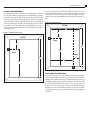
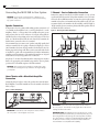
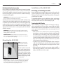
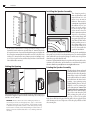
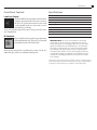
High Performance
Thin Bezel
In-Wall Subwoofer
Instruction Manual
IW-28 SUB
2
Safety Precautions
IW-28 SUB In-Wall Subwoofer
Table of Contents
2 Model IW-28 SUB
2 Unpacking the Speaker
2Description
3
3
Location Considerations
Connection Considerations
4
4
4
5
Speaker Connection
Home Theater with a Monoblock Amplifier Connection
2-Channel – Passive Subwoofer Connection
Distributed Audio Connection
5
5
6
6
6
Removing and Installing the Grille
Treating the Wall Cavity
Cutting the Opening
Installing the Speaker Assembly
Painting the Speaker Assembly
4 Connecting the IW-28 SUB to Your System
5 Mounting the IW-28 SUB
5 Installation of the IW-28 SUB
7 Front Panel Controls
7
7
Low-Pass Control
IR Knockout
7Specifications
Model IW-28 SUB
In-Wall Thin Bezel Subwoofer
Thank you for purchasing Atlantic Technology products. Our speaker systems have been designed to deliver exceptional sound and value. We hope
you like what you hear, and are happy with your decision to buy them.
Please take a few moments to read these instructions. They’re intended not
only to tell you how to mount the speaker, but how to get the best performance from it.
Unpacking the Speaker
Use care when unpacking the speaker. Remember to save all packing
materials until you are certain that the speaker has suffered no damage in
shipment. If you find such damage, either visible or internal, contact your
dealer immediately.
If you can do so, save the carton, packing pieces, and plastic bags that came
with your speakers. They will be useful in case you move or have to ship
your loudspeaker for any reason.
Description
The IW-28 SUB is a thin bezel, in-wall, passive subwoofer that has dual
8” long throw woofers, a ¾” reinforced MDF baffle and a switchable LowPass crossover that will provide you years of enjoyment. The IW-28 SUB is
designed to be used with either a monoblock amplifier, such as our SA-180
in a home theater application or as a passive subwoofer connected in parallel with the L/R speaker in a traditional 2 channel audio system. It may
also be used in a distributed audio system to add dynamic range that most
people are missing in today’s whole house installations.
For Future Reference
Record your serial numbers and date of purchase here:
Model Number
Serial Number
Date of Purchase
The serial number is found on the back panel.
Copyright © 2014 Atlantic Technology International.
Specifications are those in effect at the time of printing. Atlantic Technology reserves the
right to change specifications or designs at any time without notice.
3
Speaker Placement
Instruction Manual
Location Considerations
Choosing the location for the subwoofer is a very important consideration.
Since the IW-28 SUB can't easily be moved once it’s installed (!), very careful consideration should be given to its placement. In general, the cleanest
and most articulate delivery of bass energy into the room occurs when the
subwoofer is placed asymmetrically with respect to the room’s dimensions
and is located along the same wall as the left and right speakers. If this is
not possible, try to locate it within the front half of the room. (see fig. 1).
Such placement generally results in the best overall balance of bass impact
vs.‘one-note boom.’
If you are using two IW-28 SUB modules, follow the same advice: locate
them asymmetrically within the room and asymmetrically with regard
to each other (i.e. one near a corner, one towards the middle of a wall) to
smooth out the bass and minimize random standing wave patterns. (see
fig. 2)
Figure 2 – Dual Sub Placement
FRONT
14'
5'
Figure 1 – Asymmetrical Placement
FRONT
Good
5'
18'
13'
Good
Good
18'
13'
3'
11'
Connection Considerations
Choosing how you connect the IW-28 SUB is dependent upon your application. In a Home Theater it should be powered by an external monoblock
amplifier, such as Atlantic Technology’s SA-180 with its EQ circuit that was
specifically designed to get the very best performance out of the IW-28 SUB.
In a traditional 2 Channel System it may be used as a passive subwoofer
if your receiver does not have “sub out” and/or an additional monoblock
amplifier is not desired. In a Distributed Audio system it can be used either
way depending upon your system. We will cover each of these applications
separately.
4
Connections
IW-28 SUB In-Wall Subwoofer
Connecting the IW-28 SUB to Your System
WARNING: To prevent risk of electrical shock or damage to your
equipment, always switch off the amplifier or receiver when making
any system connections.
Speaker Connection
It’s important to observe polarity while making speaker connections: red
(+) terminals on the amplifier to red (+) on the speaker, black (–) on the
amplifier to black (–) on the speaker. Look carefully at the wires you are
using and note that one of the conductors of each pair will typically be
identified by either color, printing on the outer jacket, ridges on the outer
jacket, or a thread intertwined with the wire strands. By convention, the
marked wire is connected to the red (+) terminal.
We recommend that you connect your speakers using high quality dual
conductor stranded wire of 16 gauge or heavier, for lengths up to 25 feet
(8m). Remember, the lower the gauge number, the heavier the wire. Use
heavier gauge wire for longer runs. Please contact your audio/video dealer
or installer for specific cable recommendations and further information
regarding special circumstances. The terminals themselves are designed
to allow the use of very heavy speaker wire or connectors.
Strip about ½" (13 mm) of insulation from the connecting wires. Connect
them to the appropriate push terminal, being careful to observe polarity
(positive to the red terminal, negative to the black terminal).
2 Channel – Passive Subwoofer Connection
Remove the jumpers from the IW-28 SUB’s terminals (see fig. 4). Run
speaker wires from the receiver’s left speaker terminals to one set of terminals on the IW-28 SUB. Run another set from the receiver’s right speaker
terminals to the other set of terminals on the IW-28 SUB. (see fig. 5) It does
not matter which set of terminal on the IW-28 SUB is considered ‘right’ or
‘left’. Be careful to observe consistent polarity with all the speakers. All reds
and blacks should be consistent.
Figure 4 – Removing the IW-28 SUB jumpers
Figure 5 – Connecting as a Passive Bass Module
WARNING: Before turning on the amplifier, be certain that no stray
wire strands are touching across any terminals as this might damage
your amplifier.
Home Theater with a Monoblock Amplifier
Connection
Leaving the jumpers in place, connect the speaker wires from the Monoblock amplifier to one black terminal and one red terminal on the IW-28
SUB. (see fig 3)
Figure 3 – IW-28 SUB jumpers
+
–
LEFT
IMPORTANT! Set the IW-28 SUB’s front-panel Low-Pass switch to
the “off” position. This will bypass its crossover.
+
–
RIGHT
IMPORTANT! Set the IW-28 SUB’s front-panel Low-Pass switch to
the “on” position. This will filter out any signals above 200 Hz from
reaching the IW-28 SUB module.
IMPORTANT NOTE: Each individual woofer in the IW-28 SUB is 8 ohms;
when connecting them in parallel with your front L/R speakers (as you do
when using the IW-28 SUB passively), the front L/R speakers should also
be 8 ohms minimum, so that their combined paralleled impedance does
not fall below 4 ohms. Consult your receiver’s instruction manual for
more information on its impedance drive capability.
Installation
Instruction Manual
Distributed Audio Connection
How to install the IW-28 SUB with a distributed audio system is dependent
upon your specific system. If your source has “sub out connection” follow
the “monoblock amplifier connection” instructions. You may use a channel from your amplifier to power the subwoofer or Atlantic Technology’s
SA-180 monoblock amplifier.
IMPORTANT! Set the IW-28 SUB’s front-panel Low-Pass switch to
the “off” position. This will bypass its crossover.
Alternately, remove the jumpers from the IW-28 SUB’s terminals (see fig.
4). Run speaker wires from the amplifier’s left speaker terminals to one set
of terminals on the IW28 SUB. Run another set from the amplifier’s right
speaker terminals to the other set of terminals on the IW-28 SUB. (see fig.
5) It does not matter which set of terminal on the IW-28 SUB is considered
‘right’ or ‘left’. Be careful to observe consistent polarity. All reds and blacks
should be consistent.
IMPORTANT! Set the IW-28 SUB’s front-panel Low-Pass switch to
the “on” position. This will filter out any signals above 200 Hz from
reaching the IW-28 SUB module.
IMPORTANT NOTE: Each individual woofer in the IW-28 SUB is 8
ohms. Consult your amplifier’s instruction manual for more information on its impedance drive capability.
Mounting the IW-28 SUB
NOTE: We recommend a
professional be involved in
the installation of In-wall
speakers, if at all possible.
The IW-28 SUB woofer module
can be easily mounted in most
any standard wall material, from
½ to 1½ inches thick. Its rotating
wall clamps (sometimes called
“dog legs”) firmly fix it to the wall
surface after the proper cutout
has been made.
IMPORTANT! Keep the sides of the mounting hole at least 1½ inches
away from beams or studs to ensure that the clamps have adequate
room to rotate into position. A stud or other obstruction that’s too
close will stop them from properly doing their job.
5
Installation of the IW-28 SUB
Removing and Installing the Grille
Remove the grille from the speaker using the enclosed tool, an awl or the
point of a drywall screw in a grille opening near one of the grille corners.
Slowly pry the grille away from the frame, being careful not to damage the
speaker’s frame or its finish.
To re-install the grille later, press it carefully into position, over the frame
assembly. The grille is secured by magnets in the frame and fits snugly.
Please take your time and use care when installing the grille.
Treating the Wall Cavity
The IW-28 SUB does not require a back-box. It is designed to work properly in a standard full-sized wall cavity. This is commonly called an “infinite
baffle” installation. However even though there is no back-box, you should
exercise good acoustic/mechanical common sense, and prepare the wall
cavity as follows:
• Make sure there are no extraneous house electrical wires, plumbing,
junction boxes, or other loose items that could rattle or vibrate from the
IW-28 SUB’s output. Seal all the holes in the cavity with flexible caulking. A subwoofer moves a considerable amount of air, and if something
can rattle, it probably will rattle. It’s much, much easier to ‘button everything down’ securely before you install the sub then it is to try to hunt
down an intrusive buzz or rattle later on.
• Seal all the stud-to-drywall seams with a flexible silicone construction
caulk. This will help keep the drywall itself from flexing and rattling
against the studs, and it helps form a more airtight “enclosure” for the
IW-28 SUB.
• Fill the wall cavity loosely with acoustic speaker stuffing (“polyfill” or
unfaced fiberglass insulation). Do not pack the stuffing in the cavity
tightly, as that will reduce the bass output.
6
Installation
IW-28 SUB In-Wall Subwoofer
Installing the Speaker Assembly
• If this is new construction, we strongly recommend using 5⁄8” or ¾”
drywall. It’s heavier and more expensive than ½” material, but it’s far,
far superior in terms of acoustic/mechanical integrity and rigidity. We
also strongly recommend that the drywall be screwed to the studs every
6 inches or so, instead of the more common practice of nailing it every
12-18”. Use screws for at least a full stud bay on either side of where the
IW-28 SUB will be mounted.
Cutting the Opening
20 3⁄8”
(518mm)
11 1⁄8”
(283mm)
IW-30
LCR & IW-28
IWTS-30
LCRSUB
Mounting
Mounting Template
Template
Mount frame as shown,
with IR knockout in
upper-right corner.
Remove scrim before
painting grille.
After determining the best location for the speaker as outlined earlier, use a
level with the template to mark out the hole. Then using care, cut the proper
size hole. (11 1/8” x 20 3/8”)
WARNING: Exercise extreme care before making any wall cuts to
ensure that you will not cut through any wires, pipes, or other items
that may be in the wall. You may sometimes, but not always, be able
to determine the approximate location of wires and pipes by looking
at the locations of nearby outlets and plumbing. But their location or
absence is never an assurance that there is not something within the
wall cavity.
The clamping mechanism accommodates wall
material from ½ to 1½
inches (13 to 38 mm) in
thickness. There must be
a minimum depth behind
the wall face of 3-5⁄8” (92
mm). As noted earlier,
be sure to keep the edges
of the cutout at least 1½
inches (38mm) away from
any stud or obstruction,
as the rotating clamps will
not operate properly if you
don’t. There are holes in the
baffle providing access to
the rotating clamp screws
(See fig left). There is no
need to disassemble the
speaker for installation.
Insert the speaker assembly into the cutout and using a level carefully align
the speaker so it is level. Loosen the mounting screws ½ turn, then tighten
them, which will cause the attached clamps to unlock, rotate and position
themselves properly behind the wall.
Continue to tighten until the frame is snug in the wall.You want the bezel to
conform to the wall surface, and the frame not to rattle from the speaker’s
vibration, but be very careful not to over tighten the screws.
Painting the Speaker Assembly
The white plastic frame and metal
grille may be left as is, or painted to
match your décor.You can paint the
frame before or after it is installed
in the wall.You will need to remove
the baffle from the frame before
painting. Spray painting (using
slightly thinned paint) is the best
method to use for painting the
grille. Be sure to remove the
scrim cloth before painting the
grille. Start at one corner and gently peel the scrim from the grill.
After painting the grille, use air
pressure to “blow out” any grille
holes that are filled in with paint. When the grille is dry, re-apply the scrim
cloth. You may need to use a light coat of low tack spray adhesive to hold
the scrim in place.
Specifications
Instruction Manual
Front Panel Controls
Low-Pass Control
The IW-28 SUB has a front-mounted control that selects
or bypasses the speaker’s built-in Low-Pass crossover. Set
this to the “off” position when connected to the SA-180
or other amplifier. In this case, the receiver is used to
control the low pass filtering.
Set it to “on” only when using it in the “passive” mode, powered by 2 channels of amplification.
IR Knockout
There is an IR “knockout” plug in the upper right corner
of the baffle behind the logo. If you need, you can install
a standard IR receiver in the knockout hole.
Should you have any questions or problems please contact us at 781-7626300 or through our web site, www.atlantictechnology.com.
7
Specifications
IW-28 SUB
Overall Dimensions (W x H x D)
12 5⁄8 x 217⁄8 x 3 7⁄8" (319 x 554 x 100mm)
Cut-out Dimensions (W x H) 111⁄8 x 20 3⁄8” (283 x 518mm)
Drivers/Design Dual 8” (203mm) long-throw, 40mm voice coils
Frequency Response 38-200 Hz +/- 3dB, passive response
Recommended Amplifier Power 30-200 Watts RMS
Low-pass Filter Frequency 200 Hz
Sensitivity 89dB
Impedance Each individual woofer 8 ohm; paralleled 4 ohms
IMPORTANT NOTE: The power recommendation for this speaker
assumes that you will not operate your amplifier/receiver in a way
that produces distortion. Even rugged speakers like ours can be damaged by an amplifier driven into audible distortion. The harsh amplifier distortion (“clipping”) that occurs in this situation will eventually
cause damage to the speaker system. This type of damage may be
cumulative and can build up over time, as the amplifier is driven into
overload again and again. Such damage is easily identifiable through
examination of the damaged speaker’s voice coil and is not covered
by the warranty.
Specifications are those in effect at the time of printing. As part of our ongoing program of
continuous product improvement, Atlantic Technology reserves the right to change specifications
or appearance at any time without notice or obligation to modify existing product..
Warranty
First, we’d like to thank you for purchasing an Atlantic Technology product. We wish you
many years of enjoyment and satisfaction from it.
Second, be aware that you don’t have to send in any Warranty card to be covered by the
Limited Warranty. All you need to do is keep your original Invoice or Bill of Sale for proof of
purchase, meet the stated requirements, and follow the instructions listed within that Warranty. Please attach your Original Invoice or Bill of Sale to this manual as proof of purchase
and keep them in a safe place.
VERY IMPORTANT NOTE: PLEASE NOTE THAT ATLANTIC TECHNOLOGY PRODUCTS
CARRY ONLY A 90 DAY LIMITED WARRANTY. YOU MUST MEET ALL THE BELOW
REQUIREMENTS AND REGISTER ONLINE IN ORDER TO BE COVERED BY THE FREE
EXTENDED SERVICE AGREEMENT TO ASSURE EXTENDED FREE PROTECTION!!
Free Extended Service Agreement
Atlantic Technology offers a free Extended Service Agreement that provides enhanced
protection against product defects. In order to qualify for the free Extended Service Agreement you must:
1. Have purchased your Atlantic Technology products from an Authorized Atlantic Technology Reseller or Installer.
2. Go to www.atlantictechnology.com and click on Support>Register Your Warranty.
Fill out the required information. Be sure to have your home address, name, address
and invoice from the business you purchased, and the serial numbers of all Atlantic
Technology products purchased. THIS MUST BE DONE WITHIN 30 DAYS OF
PURCHASE.
3. If you purchased multiple Atlantic Technology products you will be able to enter them
all using one online form. Model and Serial numbers can be found on the back of each
unit and on the outside of their respective boxes.
Once all the criteria have been met, you qualify for a free Extended Service Agreement that
entitles you to additional coverage against defects in workmanship and manufacturing for
a period of up to 5 years on passive speakers and up to 1 year on powered speakers (including subwoofers). This coverage is in addition to the 90 Day Limited Warranty included with
all Atlantic Technology products.
If you are not able to register your product using the internet, please call customer service
at 781.762.6300.
Limited Warranty
Statement of Warranty: Atlantic Technology International Corp. warrants Atlantic Technology
Products to be free from defects in material and workmanship for 90 days from the time of original purchase. This Warranty covers the original retail purchaser of this product only and is valid
only in the Continental United States, Alaska, and Hawaii and all US Possessions.
To obtain Warranty service: Please contact your local Atlantic Technology reseller to determine if they are an Authorized Repair Center for Atlantic Technology products.You will need
your original Invoice or Bill of Sale to prove Warranty eligibility. If your local dealer is not
an Authorized Warranty Center you may contact us at 781-762-6300 for further help or to
send the product back to us for service and repair.You must first get a Return Authorization
Number from us to ship the product back, so it is imperative that you call us first.
What we are responsible for: We will pay for all labor and parts for covered items. If the
repairs are eligible for coverage under the terms of this Warranty we will also pay for return
shipping charges to you.
What you are responsible for: You must pack the product properly for safe shipping to your
Authorized Dealer or us. You are responsible to pay for all packing, shipping, and insurance
costs to get the unit(s) back to Atlantic Technology or your Authorized Dealer.
Optional replacement: We, at our option, may replace rather than repair your Atlantic Technology product with a new or reconditioned one of the same or similar design. The repair
or replacement will be warranted for 90 days from date of receipt back to you. All details
in terms of eligibility for an Extended Service Agreement will carry over from the original
purchase to the replacement item.
What this Warranty does not cover: This Warranty does not cover defects resulting from
accidents, damage while in transit, alterations, unauthorized repair, failure to follow instructions, misuse, fire, flood, and Acts of God. This Warranty will be void if the product’s serial
number has been altered or removed or if the product has been modified or defaced.
Exclusions and Limitations: Implied warranties, including those of fitness for a particular
purpose and merchantability (an unwritten warranty that the product is fit for ordinary use)
are limited to the period of any Warranty granted hereby. We will not pay for loss of time,
inconvenience, loss of use, or property damage caused by your Atlantic Technology product
or its failure to work, or any other incidental or consequential damages.
State law rights: Some states do not allow the exclusion or limitation of incidental or consequential damages, so the above limitation or exclusion may not apply to you. This Warranty
gives you specific legal rights, and you may have other rights which vary from state to state.
This Warranty is valid only when Atlantic Technology products are purchased from an Authorized Atlantic Technology Reseller in the Continental United States, Alaska, and Hawaii and all
US Possessions. If you purchase Atlantic Technology products outside the United States please
consult your local distributor or reseller for applicable Warranty coverage and restrictions.
Should you have any questions or problems please feel free to contact us at 781-762-6300 or
through our web site, www.atlantictechnology.com.
Extended Service Agreement (only available in the Continental United States,Alaska, and
Hawaii and all US Possessions): You must complete the Extended Service Agreement application, and meet all of the purchase criteria stated on that application, to receive an Extended
Service Agreement that covers your Atlantic Technology products well beyond the standard 90
day Warranty.
343 Vanderbilt Avenue Norwood, MA 02062 (781) 762-6300 www.atlantictechnology.com
015-1028