1
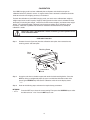
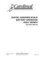
Cardinal
®
Cardinal Scale Manufacturing Co.
DIGITAL HANGING SCALE
BATTERY OPERATED
HSDC SERIES
Operation Manual
8551-M256-O1 Rev J
06/05
PO BOX 151, WEBB CITY, MO 64870
PH 417-673-4631 • FAX 417-673-5001
Web site-http://www.cardinalscale.com
Printed in USA
2
Office, Washington, DC 20402; Stock No. 004000-00345-4.
TABLE OF CONTENTS
Introduction .................................................... 1
Specifications ................................................. 1
Battery Installation ......................................... 2
Scale Operation ............................................. 3
Tare Weight Entry ........................................... 4
Display Codes ................................................ 5
Calibration ...................................................... 6
Setup Review ................................................ 10
Sealing .......................................................... 10
Do’s And Don’ts ............................................. 10
In Case Of Difficulty ...................................... 11
INTRODUCTION
Congratulations on selecting a Cardinal Series
HSDC digital hanging scale. This precision
weighing instrument is designed to provide
years of trouble-free operation while
maintaining a high degree of weighing
accuracy. This manual contains information on
the proper care and use of this instrument.
Before using the instrument, read
this manual and pay special
attention to all “Warning”
Symbols.
Serial Number_________________________
Date Of Purchase______________________
Purchased From_______________________
_____________________________________
Retain This Information For Future Use
NOTICE
WARNING! This equipment generates and uses
radio frequency energy and if not installed and
used properly, that is, in strict accordance with
the manufacturer’s instructions, may cause
interference to radio and television reception. It
has been type tested and found to comply with
the limits for a Class B computing device in
accordance with the specifications in Subpart J
of Part 15 of FCC Rules, which are designed to
provide reasonable protection against such
interference in a residential installation.
However, there is no guarantee that interference
will not occur in a particular installation. If this
equipment does cause interference to radio or
television reception, the user is encouraged to
try to correct the interference by one or more of
the following measures:
All rights reserved. Reproduction or use of
editorial or pictorial content, in any manner,
without written, expressed permission is
prohibited. No patent liability is assumed with
respect to the use of the information contained
herein. While every precaution has been taken
in the preparation of this book, the Seller
assumes no responsibility for errors or
omissions. Neither is any liability assumed for
damages resulting from the use of the
information contained herein. All instructions
and diagrams have been checked for accuracy
and ease of application; however, success and
safety in working with tools depends to a great
extent upon individual accuracy, skill and
caution. For this reason, the Seller is not able
to guarantee the result of any procedure
contained herein. Nor can they assume
responsibility for any damage to property or
injury to persons occasioned from the
procedures. Persons engaging the procedures
do so entirely at their own risk.
1. Reorient the receiving antenna.
2. Relocate the instrument with respect to the
receiver.
3. Move the instrument away from the
receiver.
4. Plug the instrument into a different outlet
so that the instrument and receiver are on
different branch circuits.
SPECIFICATIONS
Capacity ......................... see table
Graduation size .............. see table
Tare/Rezero capacity ..... 4% or 100% of scale
capacity
Operating temperature ... -10˚ to +40˚C,
14˚ to 104˚F
Storage temperature ...... -10˚ to +60˚C,
14˚ to 140˚F
Display type .................... 4 digit, 1" high LCD
Battery requirements ...... 6 each “C” size
alkaline
Weight ............................ 5 lb
Ultimate safe overload .... 200%
If necessary, the user should consult the dealer
or an experienced radio/television technician for
additional suggestions. The user may find the
following booklet prepared by the Federal
Communications Commission helpful: “How to
Identify and Resolve Radio-TV Interference
Problems.” This booklet is available from the U.S.
Government Printing.
1
SPECIFICATIONS, Cont.
Model
HSDC-200
HSDC-100
HSDC-40
HSDC-20
HSDC-500
HSDC-100KG
HSDC-40KG
HSDC-20KG
Capacity
Graduation
200 lb
100 lb
40 lb
20 lb
500 lb
100 kg
40 kg
20 kg
200 x 0.1 lb
99.95 x 0.05 lb
40 x 0.02 lb
20 x 0.01 lb
500 x 0.2 lb
99.95 x 0.05 kg
40 x 0.02 kg
20 x 0.01 kg
OFF
G
GROSS
T
TARE
N
NET
ON
ZERO 0
BATTERY INSTALLATION
Before weighing operations can begin it will be necessary to install the batteries in the HSDC
hanging scale. This same procedure should also be followed when battery replacement becomes
necessary. Make certain that only “C” size alkaline batteries are used as replacements.
NOTE! Exposure of batteries to high temperatures (above 140° F) will decrease
their capacity resulting in shorter operation time.
Step 1
Using a screwdriver, remove the two retaining screws from the back of the instrument. Remove the
battery compartment cover.
Battery Compartment
Cover
Remove these screws
Step 2
Remove the old batteries, if present. Insert six new “C” cells making certain that each cell is
correctly positioned. Refer to the next diagram for proper battery placement.
2
BATTERY INSTALLATION, Cont.
Battery Pack
Battery
Battery Compartment Cover
Step 3
Replace the battery compartment cover and retaining screws.
NOTE! If the HSDC scale fails to operate after battery replacement check to
make certain that each of the six cells has been installed correctly. One cell
installed backward will prevent the scale from operating.
SCALE OPERATION
Before weighing operations can begin it will be necessary to install batteries in the scale. Refer to
the battery installation section of this manual for additional information.
Hang the scale from a support that is strong enough to support the weight of the scale PLUS the
weight of the material that is to be weighed.
Hang the load receiving element on the hook on the bottom of the scale and press the ON/ZERO
key. Look at the weight display. If the display does not indicate zero weight, press the ON/ZERO
key again to reset the display to zero.
Place the material to be weighed in the receiving element and read the weight in the scale display.
Refer to the figure below for the identification of scale components:
Weight Display
Window
Net Annunciator
Low Battery
Indicator
OFF Key
OFF
G
GROS
S
T
TARE
N
ON
NET
ZERO 0
Zero Indicator
GROSS, TARE
and NET Keys
ON/ZERO Key
3
SCALE OPERATION, Cont
Scale Component Identification
Press to turn the scale off. The auto-shutoff feature will turn the scale off automatically after
a preselected time of inactivity (no motion).
OFF
Press to place the scale in the gross weight display mode (net indicator off).
G
GROSS
Press to enter a new tare weight value equal to the current scale weight. The scale will
automatically enter the net weight display mode (net indicator on).
T
TARE
Press to enter the net weight display mode without entering a new tare weight value (net
annunciator on).
N
NET
Press to turn the scale on. If on, press to zero the weight display up to the preset zero limit
(4% or 100% of the scale capacity).
ON
ZERO
0
The membrane keyboard is not to be operated with pointed objects (pencils, pens,
fingernails, etc). Damage to keyboard resulting from this practice will NOT be covered
under warranty.
Annunciators
•
NET
•
•
LO BAT Illuminated to signal that the batteries should be replaced.
Illuminated to indicate the scale is in the net weight mode. If it is off, it indicates that
the scale is in the gross weight mode.
ZERO
Illuminated to show that the scale weight is within 1/4 graduation of the center of zero.
TARE WEIGHT ENTRY
The HSDC has an automatic tare feature that allows you to enter tare weight up to the three least
significant digits of the scale capacity. This tare weight feature is often used to subtract the empty
container weight or other unwanted fixed weight values from the weight reading. See the PUSH
BUTTON TARE setup mode section to activate this feature.
The following table lists the maximum tare weight allowed for each model of the HSDC scale.
MODEL
HSDC-500
HSDC-200
HSDC-100
HSDC-40
HSDC-20
HSDC-100KG
HSDC-40KG
HSDC-20KG
CAPACITY
500 lb X 0.2 lb
200 lb x 0.1 lb
99.95 lb x 0.05 lb
40 lb x 0.02 lb
20 lb x 0.01 lb
99.95 kg x 0.05 kg
40 kg x 0.02 kg
20 kg x 0.01 kg
TABLE 1
4
MAXIMUM TARE WT
99.8 lb
99.9 lb
9.95 lb
9.98 lb
9.99 lb
9.95 kg
9.98 kg
9.99 kg
TARE WEIGHT ENTRY, Cont.
Pressing the TARE key will cause the currently displayed gross weight to be stored as the new tare
weight and cause the scale to enter the net weight display mode. The net weight display mode is
indicated by turning on the net annunciator. For example, on a HSDC-20, if the displayed gross
weight is 2.00 lb and you press the TARE key, the 2.00 lb would be entered as the new tare weight.
The scale would then enter the net weight mode and subtract the 2.00 lb tare value from the gross
weight displaying a net weight of 0.00 lb. If you added another 2.00 lb to the platform, the display
would indicate 2.00 lb of net weight. Pressing the GROSS key would return the scale to the gross
weight display 4.00 lb. NOTE: Remember the scale will only weigh to its maximum capacity. Any
combination of NET plus TARE weights over the scale capacity will result in a overload condition
and display ot. For example, using the HSDC-20 from above, with tare weight of 2.00 lb, adding
19.00 lb to the platform will cause an overload condition. This is because 2.00 lb tare weight plus
19.00 lb load weight equals 21.00 lb gross weight, which exceeds the capacity of the scale.
DISPLAY CODES
During operation of the HSDC hanging scale you may encounter a special display message. The
following lists display codes and their meaning.
DISPLAY
MEANING
-oC-
Scale overloaded, remove excess load to resume operation.
UnSt
Motion is present when attempting to power-up, zero the weight display or enter a
tare value.
UnLd
The weight on the scale exceeds the zero range on power-on. Remove the load.
LoAd=
The scale load is less than the zero range on power-on.
-oF-
Attempting to display a negative number less than -999.
CALb
Indicates that the scale has not been calibrated or has been interrupted during the
calibration process.
Err
Disallowed keyboard entry: attempted to zero with the weight outside the zero
range.
5
CALIBRATION
Your HSDC hanging scale has been calibrated prior to shipment and should not require recalibration before it is placed in service. A regular check of the instrument’s calibration should be
made to ensure that its weighing accuracy is maintained.
To check the calibration of your HSDC hanging scale, you must have a calibrated test weight or
weights equal to the scale’s capacity. Begin by making certain that the scale is unloaded and that
the display is indicating zero weight. Load the scale with the test weight(s) and observe the weight
display. If the displayed weight is different from the total test weight value, calibration may be
necessary. Note that a qualified scale technician should be consulted before any attempt at
calibration is made.
NOTE! This scale is provided with a means of attaching a seal to prevent access
to the calibration switch.
Calibration Procedure
Step 1.
Remove the seals (if present) from the calibration cover plate, then remove the two
retaining screws and cover plate.
Retaining Screw
Cover
Plate
Seals
Underside of
Scale
Step 2.
Hang the scale from a suitable support and attach the load receiving device. Press the
OFF key. Using a straightened paper clip, press and hold the calibration switch while
pressing the ON/ZERO key. Release the calibration switch when the display shows
int=.
Step 3.
Refer to the following steps and enter the required setup parameters.
INTERVAL
int=
Press the NET key to show the current setting. Then press the ON/ZERO key to select
the desired value: 1-2-5. Press the NET key to save.
6
CALIBRATION, Cont.
DECIMAL POINT
Press the NET key to show the current setting. Then press the ON/ZERO key to
dPP=
select the desired value:
0=XXXX
1=XXX.X
2=XX.XX
3=X.XXX
Press the NET key to save.
CAPACITY
Press the NET key to show the current capacity setting. Then press the ON/ZERO
CAP=
key to advance the flashing digit from 0 through 9 (200.0). Select the value then
press the TARE key to advance to the next digit location (200.0). Repeat the
process until the capacity has been entered. Press the NET key to save.
WEIGHING UNITS
Press the NET key to show the current setting. Then press the ON/ZERO key to
Unt=
select the desired value: 1-2 where 1=Pounds Only and 2=Kilograms Only. Press
the NET key to save it.
(Please note, although selection 3 will display and can be selected, it is INVALID
for the HSDC scale.)
CALIBRATION WEIGHT
Press the NET key to show the current calibration weight. Then press the ON/
Lod=
ZERO key to advance the flashing digit of calibration weight from 0 through 9
(150.0). Select the value then press the TARE key to advance to the next digit
location (150.0). Repeat the process until the calibration weight has been
entered. Place this amount of calibration test weights on the scale, then press the
NET key. The display will show ---- then:
Remove the test weights and press the NET key. The display will show ---UnLod
then proceed to the next prompt.
ZERO TRACKING RANGE
Press the NET key to show the current division setting. Values of 0 through 9 and
trA=
0.5 are valid for the zero tracking range. Press the ON/ZERO key to step through
and select 0.5 as the division value, then press the NET key to save. If a zero
tracking range division of 0 through 9 is desired, first press the ON/ZERO key to
select 0, then press the TARE key to advance to the next digit location and press
the ON/ZERO key to select 0 through 9 divisions. Press the NET key to save.
4% ZERO TRACKING LIMIT
Press the NET key to show the current setting. Then press the ON/ZERO key to
trL=
toggle between yes and no. YES=4% limit, no=100% limit. Press the NET key to
save. (NOTE: 4% limit is for Canadian use)
POWER UP ZERO
Press the NET key to show the current setting. Then press the ON/ZERO key to
PUO=
toggle between yes and no. YES=enable, no=disable. Press the NET key to save.
FILTERING
FLt=
F=
Press the NET key to show the current level of filtering. Then press the ON/ZERO
key to select the desired value:
0=no filtering
1=minimal filtering
2=moderate filtering
3=custom filtering
Press the NET key to save setting.
If you select level 3 then:
Press NET to show current filter weight setting. Press ON/ZERO to select filter
weight level (1 through 99,-99 being the greatest filtering and 1 the least). Press
the NET key to save setting.
7
CALIBRATION, Cont
BREAKPOINT
b=
Press NET to show the current break point setting. Press ON/ZERO to select
break point setting (1 through 99). Press the NET key to save setting.
MOTION RANGE
Press the NET key to show the current motion range in divisions. Then press the
UnS=
ON/ZERO key to select the number of digits to change before motion: 0 through
9. Press the NET key to save.
SAMPLE RATE
Sr=
Press the NET key to show the current sample rate setting. Values of 1 through
12 are valid for the sample rate. Press the ON/ZERO key to select 1 through 9
samples per second, then press the NET key to save. If a sample rate of 10
through 12 is desired, first press the ON/ZERO key to select 0 through 2, then
press the TARE key to advance to the next digit location and press the ON/ZERO
key to select 10 through 12 samples per second. Press the NET key to save.
AUTOMATIC SHUTOFF
Press the NET key to show the current setting. Then press the ON/ZERO key to
ASh=
disable the feature or to select the number of minutes of inactivity before turning off
the scale. 0= disable, 1 to 9= minutes of inactivity before shutoff. Press the NET
key to save it.
SLEEP MODE
SLP=
Press the NET key to show the current setting. Then press the ON/ZERO key to
disable the feature or to select the number of minutes at zero before going to sleep.
0=disable, 1 to 9=minutes of inactivity before sleeping. Press the NET key to save
it.
PUSH BUTTON TARE
Press the NET key to show the current setting. Then press the ON/ZERO key to
Pbt=
toggle between yes and no. YES=enable, no=disable. Press the NET key to save.
The display will display the software revision number and then the gross weight. The setup and
calibration process has been completed and the scale is ready to weigh. Place the test weight back
on the scale to verify calibration.
8
CALIBRATION, Cont
Calibration Switch
Front of Instrument
Underside of Scale
Model
HSDC
500
200
100
40
20
100kg
40kg
20kg
Table 1 -- Setup Settings for HSDC Models
int=
2
1
5
2
1
5
2
1
dPP=
1
1
2
2
2
2
2
2
CAP=
5000 2000 9995 4000 2000 9995 4000 2000
Unt=
1
1
1
trA=
0.5
0.5
trL=
no
PUO=
1
1
1
1
1
0.5
0.5
0.5
0.5
0.5
0.5
no
no
no
no
no
no
no
no
no
no
no
no
no
no
no
FLt=
1
1
1
1
1
1
1
1
UnS=
1
1
1
1
1
1
1
1
Sr=
trL= YES is for Canadian
use
Skip if FLt= 1 or 2
ASh=
2
2
2
2
2
2
2
2
SLP=
1
1
1
1
1
1
1
1
Pbt=
y
y
y
y
y
y
y
y
End of Calibration Section. Go to Setup Review/Fine Span.
9
SETUP REVIEW
The HSDC allows several operational parameters to be reviewed and changed as necessary
without having to break the calibration seal and enter the setup and calibration mode. The setup
review allows changes to be made to the power up zero setting, the automatic shutoff and sleep
mode delay times, push button tare.
To enter the setup review mode, simply turn the HSDC off, then press and hold any key other than
ON/ZERO or the OFF keys and press the ON/ZERO key. The display will prompt for the power up
zero selection. Refer to the instructions listed in the Calibration Procedure section of this manual for
information on how to change these parameters.
The parameters in the setup review will be processed in the following sequence:
POWER UP ZERO
AUTOMATIC SHUTOFF TIME
SLEEP MODE TIME
PUSH BUTTON TARE
Fine Span
The span can be fine-adjusted while the indicator is on by pressing and holding the calibration
switch and pressing the ON/ZERO or NET key:
Calibration Switch + ON/ZERO = increase
Calibration Switch + NET = decrease
Go to Sealing Instructions
SEALING INSTRUCTIONS
To attach the seals, first make certain the two cover plate retaining screws are snug then thread the
seal wires through the hole in the screw heads as shown in the calibration section of this manual.
DO’S and DON’TS
1. DO hang the scale from a support that is strong enough to support the weight of the scale plus
the weight of the material to be weighed. The more rigid the support the better.
2. DON’T shock load your HSDC hanging scale with weights greater than 10 percent of the scale’s
capacity by throwing the weight on the scale.
3. DO replace batteries as soon as the weight display shows the low battery signal.
4. DON’T hose down or submerse the scale in any liquid.
5. DO use only a damp cloth and mild detergent to clean the outside of the scale.
6. DON’T disassemble the scale. There are no user-serviceable components within the scale.
10
DO’S AND DON’TS, Cont.
7. DO use only high quality Alkaline “C” size replacement batteries.
8. DON’T use sharp objects to press the keys. Use only your finger tip.
9. DO check scale calibration regularly to ensure that the high degree of weighing accuracy is
maintained.
10. DON’T modify or replace the loading hook or hanging eye with lower capacity parts.
11. DO remove loads which produce the over capacity (-oC- ) display as soon as possible.
IN CASE OF DIFFICULTY
Your HSDC hanging scale has been designed to provide years of trouble free service. Should you
encounter a problem with your scale refer to the chart below before contacting your scale
technician.
Problem
Possible Cause/Solution
1. Scale seems dead
A. Batteries improperly installed, make certain each of the six batteries
is correctly installed.
No display
2. Incorrect weight
display
B. Batteries are discharged completely, replace with fresh batteries.
A. Scale not at zero prior to applying weight, remove load and reset
to zero by pressing ON/ZERO key.
B. Scale is not calibrated. Refer to Calibration Section of this manual.
C. Scale in net mode. Press the GROSS key.
If you are unable to resolve the difficulty, contact the Cardinal Scale representive from whom you
purchased the scale. He will be able to provide you with information concerning the return and
repair of your scale. Make certain that you obtain a return authorization number prior to returning
the scale. This number should appear on the shipping carton and all correspondence referencing
the repair. Failure to obtain a return authorization number will result in unnecessary delay.
11
2
2
GNED
I
S
E
D
TURED
AC
&
M ANUF
.
A
I N U .S .