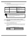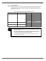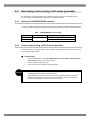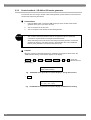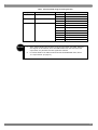
1
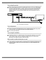
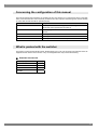
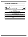
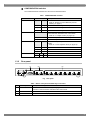
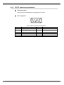
HDMI Switcher VD-1673 Instruction Manual Ver 1.10 HDMI Switcher VD-1673 Instruction Manual 2009.5 Ver1.10 ASTRODESIGN,Inc CONTENTS INTRODUCTION................................................................................................................................................ v SAFETY PRECAUTIONS................................................................................................................................... v In order to ensure safe operation ............................................................................................................ v Concerning the power cord ..................................................................................................................... v Concerning foreign matter....................................................................................................................... v Concerning this product ..........................................................................................................................vi Concerning impact ..................................................................................................................................vi Concerning the installation ......................................................................................................................vi When trouble or malfunctioning has occurred .........................................................................................vi Concerning the configuration of this manual .....................................................................................................vii What is packed with the switcher ......................................................................................................................vii Chapter 1 CONCERNING THE VD-1673 ................................................................................................................ 1 1.1 General description ................................................................................................................................. 1 1.2 Features.................................................................................................................................................. 1 1.3 Panel parts and their functions................................................................................................................ 2 1.3.1 Front panel................................................................................................................................... 2 1.3.2 Rear panel ................................................................................................................................... 3 1.4 Sequence of settings............................................................................................................................... 4 1.5 Examples of connections ........................................................................................................................ 5 Chapter 2 2.1 CONTROL METHODS (CONTROL MODES)......................................................................................... 7 Exercising control using the switcher’s front panel switches ................................................................... 7 2.1.1 Setting the CONFIGURATION switches ...................................................................................... 7 2.1.2 Control method ............................................................................................................................ 8 2.2 Exercising control using the switcher’s EXT I/F connector...................................................................... 8 2.2.1 Setting the CONFIGURATION switches ...................................................................................... 8 2.2.2 Control method ............................................................................................................................ 9 2.3 Exercising control using a VG series generator .................................................................................... 10 2.3.1 Setting the CONFIGURATION switches .................................................................................... 10 2.3.2 Control method using a VG-870 series generator...................................................................... 10 2.3.3 Control method - VG-849 or 859 series generator..................................................................... 12 Chapter 3 3.1 DESCRIPTION OF FUNCTIONS.......................................................................................................... 15 Output mode ......................................................................................................................................... 15 3.1.1 SELECTION mode..................................................................................................................... 15 3.1.2 DISTRIBUTION mode................................................................................................................ 15 3.2 Input port selection................................................................................................................................ 16 3.3 Output port selection ............................................................................................................................. 16 3.4 Pre-emphasis level................................................................................................................................ 16 3.5 Operations during power OFF............................................................................................................... 17 i Chapter 4 4.1 PRODUCT SPECIFICATIONS.............................................................................................................. 19 Main specifications................................................................................................................................ 19 4.1.1 Input/output specifications ......................................................................................................... 19 4.1.2 EXT I/F specifications ................................................................................................................ 19 4.1.3 General specifications................................................................................................................ 20 4.2 Connector specifications ....................................................................................................................... 21 4.2.1 HDMI connector specifications .................................................................................................. 21 4.2.2 EXT I/F connector specifications................................................................................................ 22 4.3 Precautions ........................................................................................................................................... 23 Concerning the performance of the VD-1673........................................................................................ 23 Concerning the CONFIGURATION switches ........................................................................................ 23 Concerning the CEC line....................................................................................................................... 23 Concerning the pre-emphasis level....................................................................................................... 23 Concerning the “DISTRIBUTION” output mode .................................................................................... 23 ii Updated version history Ver. Date 1.00 2009/03/16 1.10 2009/04/07 Page Section no. Description of changes made Initial version 10 2.3.2 23 4.3 -- -- Added “Control method - VG-870 series generator.” Added “Concerning the CONFIGURATION switches.” Errors corrected, etc. iii iv BEFORE OPERATION INTRODUCTION Thank you very much for purchasing this HDMI switcher. This manual contains details on the operation procedures to be followed when the VD-1673 is used, the checkpoints and precautions to be observed, and so on. Improper handling may result in malfunctioning so before using the VD-1673, please read through these instructions to ensure that you will operate the switcher correctly. Keep this manual in a safe place for future reference. SAFETY PRECAUTIONS Malfunctioning or trouble may result if this product is not handled properly. Before proceeding to operate the product, be absolutely sure to read the safety precautions set forth below to ensure proper operation. In order to ensure safe operation Do not subject the switcher to impact or throw it. Doing so may cause the switcher to malfunction, explode or generate abnormally high levels of heat, possibly resulting in a fire. Do not use the switcher where there is a danger of ignition or explosions. Do not place the switcher inside a microwave oven or other heating kitchen appliance or inside a high pressure vessel. Doing so may heat up the switcher to abnormally high levels, cause smoking, running the risk of the switcher’s catching fire and/or damaging the circuit components. This switcher contains some high-voltage parts. If you touch them, you may receive an electric shock and burn yourself so do not attempt to disassemble, repair or remodel the switcher. If there is a thunderstorm while the switcher is being used outdoors, immediately turn off its power, disconnect the power cable from the main unit, and move the switcher to a safe place. Concerning the power cord Always take hold of the molded part of the plug when disconnecting the power cord. Do not use force to bend the power cord or bunch it up for use. Doing so may cause a fire. Do not place heavy objects on top of the power cord. Doing so may damage the cord, causing a fire or electrical shock. Concerning foreign matter Do not spill liquids inside the monitor or drop inflammable objects or metal parts into it. Operating the switcher under these conditions may cause a fire, electric shocks and/or malfunctioning. v Concerning this product When connecting this product to another unit (such as a TV set or DVD player), use the FG cable provided or a similar cable to connect the frame ground (FG) terminal on the other unit to the frame ground (FG) terminal on the VD-1673 switcher. Failure to connect these terminals may cause the product to fail or malfunction. EX T I/F Fig. IN1 IN2 OUT 1 OUT2 OUT3 OUT 4 OUT5 OUT 6 OUT 7 OUT8 Connecting the FG terminals Concerning impact This is a precision instrument and, as such, subjecting it to impact may cause malfunctioning. Take special care when moving the switcher. Do not drop the switcher. Concerning the installation Install the switcher in a stable location. Do not stand the switcher on one of its sides. Doing so may cause the switcher’s temperature to rise due to heat generation, possibly resulting in malfunctioning. When trouble or malfunctioning has occurred vi In the unlikely event that trouble or malfunctioning should occur, disconnect the switcher’s power cable, and contact your dealer or an ASTRODESIGN sales representative. Concerning the configuration of this manual This manual contains the instructions for operating the VD-1673 switcher. It is configured as shown in the table below, and it describes the control methods, precautions and other aspects. Read through the manual carefully to ensure that the switcher will be operated properly. Chapter Description INTRODUCTION This chapter describes the safety precautions, configuration of the manual and what is packed with the switcher. 1 CONCERNING THE VD-1673 This chapter gives an overview of the VD-1673 and describes its features. 2 CONTROL METHODS This chapter describes the methods used to control the VD-1673. 3 DESCRIPTION OF FUNCTIONS This chapter describes the VD-1673’s functions. 4 PRODUCT SPECIFICATIONS This chapter describes the VD-1673’s specifications. What is packed with the switcher The switcher comes with the following items. Be absolutely sure to use only the genuine accessories which are supplied with this switcher since the use of any non-designated items may cause malfunctioning. Standard accessories Accessory supplied Quantity VD-1673 main unit 1 VD-1673 instruction manual 1 Power cable 1 FG cable 1 vii viii 1 1.1 CONCERNING THE VD-1673 General description The model VD-1673 is an HDMI signal switcher which is provided with two HDMI input ports and eight output ports. It enables the input ports to be switched for TVs which have a multiple number of HDMI inputs without having to change the cable connections. When it is used together with a generator in the VG series, it enables the signals of the input ports to be monitored easily. The switcher makes it possible to distribute the TMDS signals among the HDMI input signals, and output them when HDCP is not going to be executed. 1.2 Features HDMI input selection One of the two HDMI signals supplied to the VD-1673 can be selected and output. HDMI output selection Any one of the eight ports for outputting the signals from the VD-1673 can be selected. HDMI output distribution When HDCP is not going to be executed, it is possible to distribute the TMDS signals among the HDMI input signals supplied to the VD-1673, and output them. Control method selection Three control methods are available to establish the settings to be used for selecting and distributing the HDMI input and output signals: The first method exercises control using the switches on the VD-1673 unit, the second exercises external control (TTL level) from the general-purpose connectors, and the third exercises external control from a VG series generator. Connection with a VG series generator By using the VD-1673 in combination with a VG series generator, control over the VD-1673 can be registered as a series of programmed settings in the VG series generator. 1 1.3 Panel parts and their functions 1.3.1 Front panel (1) (2) (3) 1 OUTPUT SELECT (4) (5) (6) HDMI SWITCHER INPUT SELECT P OWE R | 1 3 5 7 ON CONTROL 1 2 3 4 5 1 2 O FF O FF 2 2 4 6 8 OFF 1 2 3 4 5 ON O FF O FF ON SW No . Table OUTP UT 3 SW No . FRO NT SW O FF SEL ECTIO N EXT I/F ON DISTRIBUTIO N VG Fig. 2 VD-1673 VG P RE-E MP HA S IS 5 6 SW No . O FF O FF 0dB O N O FF 3dB O FF O N 6dB Front panel Names of the parts and what they are used for No. Name of part Description of setting 1 INPUT SELECT switch This is used to select the input ports when “front panel switches” control has been selected as the control mode. 2 INPUT SELECT LED These indicate the currently selected input port. (The lighted LED indicates the corresponding port which is currently selected.) 3 OUTPUT SELECT switch This is used to select the output ports when “front panel switch” control has been selected as the control mode. 4 OUTPUT SELECT LED These indicate the output ports which are currently selected. (The lighted LEDs indicate the corresponding ports which are currently selected.) 5 CONFIGURATION switches Refer to “CONFIGURATION switches” below (on page 3). 6 POWER switch This used to turn the power of the VD-1673 on and off. ○ Chapter 1 CONCERNING THE VD-1673 CONFIGURATION switches The CONFIGURATION switches have the functions described below. Table Name of function Switch no. CONTROL 1 OUTPUT CONFIGURATION switches Description 2 Used to set the control mode. * Refer to “Chapter 2 Control Methods (Control Modes)” (on page 7). (OFF) (OFF) Control is exercised using the “front panel switches.” (ON) (OFF) Control is exercised using the “EXT I/F connector.” (OFF) (ON) Control is exercised using a “VG series generator.” 3 Used to set the output mode when “front panel switch” control has been selected as the control mode. * Refer to “3.1 Output modes” (on page 15). (OFF) The switcher operates in the switching mode. (ON) PRE-PMPHASIS Reserve 1.3.2 The switcher operates in the distribution mode. 4 5 Used to set the pre-emphasis level of the TMDS signals. * Refer to “3.4 Pre-emphasis level” (on page 16). (OFF) (OFF) 0 dB (ON) (OFF) 3 dB (OFF) (ON) 6 dB 6 7 8 OFF OFF OFF Set all of these three switches to OFF. Rear panel (7) (8) (9) A C IN (100-240V)T 3. 15A EXT I /F IN1 IN2 OUT1 Fig. Table OUT2 OUT3 OUT4 OUT5 OUT6 OUT7 OUT8 Rear panel Names of the parts and what they are used for No. Name of part Description of setting 7 EXT I/F connector Used to control the VD-1673 by inputting signals to this connector when “EXT I/F connector” control has been selected as the control mode. 8 INPUT These are the HDMI input ports of the VD-1673. 9 OUTPUT These are the HDMI output ports of the VD-1673. 3 1.4 Sequence of settings Follow the sequence of steps below when using the VD-1673. (1) Set the control mode. Select the control mode, and set it using the CONFIGURATION switches on the front panel of the VD-1673. (2) Connecting the units Connect the units to the HDMI input and output ports of the VD-1673. (3) Setting the input ports Select the input ports in line with the control mode selected. (4) Setting the output ports Select the output ports in line with the control mode selected. (5) Setting the output mode Select the output mode in line with the control mode selected. (6) Set the pre-emphasis level. Set the pre-emphasis level of the TMDS signals. 4 Chapter 1 1.5 CONCERNING THE VD-1673 Examples of connections When controlling the switcher from the EXT I/F connector AC IN(100-240V)T3.15A EXT I/F IN1 Remote control unit or other jig リモコン等の治具 When controlling the switcher from the VG series generator Source unit Source機器1 Source unit 2 Source機器2 A C IN(100-240V)T3. 15A EXT I /F IN1 IN2 OUT1 OUT2 OUT3 OUT4 OUT5 OUT6 OUT7 OUT8 Sink units Sink機器 5 When using the SELECTION mode as the HDMI output mode VGシリーズ VG series generator A C IN(100-240V)T3. 15A EXT I /F IN1 IN2 OUT1 OUT2 OUT3 OUT4 OUT5 OUT6 OUT7 OUT8 HDCP OK EDID OK CEC OK Sink機器 Sink units When using the DISTRIBUTION mode as the HDMI output mode (* only when HDCP is OFF) VGシリーズ VG series generator A C IN(100-240V)T3. 15A EXT I /F IN1 IN2 OUT1 OUT2 OUT3 OUT4 Sink units Sink機器 6 OUT5 OUT6 OUT7 OUT8 2 CONTROL METHODS (CONTROL MODES) The following three control methods (control modes) are available for the VD-1673. Table Control modes Control mode Description Details Front panel switches The switcher is controlled using the switches on 2.1 Exercising control using the its front panel. switcher’s front panel switches EXT I/F connector The switcher is controlled by inputting signals to 2.2 Exercising control using the the EXT I/F connector. switcher’s EXT I/F connector VG series generator The switcher is controlled using the menus of a VG series generator. 2.3 Exercising control using a VG series generator Once the control method has been set, the switches of the VD-1673 must be used to set the switcher’s operations in line with the control method selected. 2.1 Exercising control using the switcher’s front panel switches The VD-1673 can be controlled using the CONFIGURATION switches, INPUT SELECT switch and OUTPUT SELECT switch on its front panel. 2.1.1 Setting the CONFIGURATION switches In order to enable control to be exercised using the switches on the switcher’s front panel, CONFIGURATION switches no. 1, 2 and 3 on the front panel must be set to the positions shown in the table below. Table CONFIGURATION switch settings Switch no. Name of function Setting 1 CONTROL OFF 2 3 OFF OUTPUT Refer to “2.1.2 Control methods” below. 7 2.1.2 Control method Set the CONFIGURATION switch, INPUT SELECT switch and OUTPUT SELECT switch on the switcher’s front panel to the positions shown in the table below. Table Control method selected using the front panel switches Setting item Operation Description Input port selection Press the INPUT SELECT switch. Each time the switch is pressed, the input port is switched. (Input 1 → input 2 → input 1) Output port selection Press the OUTPUT SELECT switch. Each time the switch is pressed, the output port is switched. (Output 1 → output 2 → output 3 ... output 8 → output 1) *1 Output mode selection CONFIGURATION switch no.3 OFF SELECTION mode *2 ON DISTRIBUTION mode *2 CAUTION 2.2 *1 When “SELECTION mode” has been set as the output mode, the TMDS, DDC and CEC signals are all switched; when “DISTRIBUTION mode” has been set as the output mode, only the DDC and CEC signals are switched. *2 For further details on the SELECTION mode and DISTRIBUTION mode, refer to “3.1 Output modes” (on page 15). Exercising control using the switcher’s EXT I/F connector The VD-1673 can be controlled using the EXT I/F connector on its rear panel. 2.2.1 Setting the CONFIGURATION switches In order to enable control to be exercised using the EXT I/F connector on the switcher’s rear panel, CONFIGURATION switches no.1 and 2 on the front panel must be set to the positions shown in the table below. Table Switch no. Name of function Setting 1 CONTROL ON 2 8 CONFIGURATION switch settings OFF Chapter 2 2.2.2 CONTROL METHODS (CONTROL MODES) Control method Set the signals of the EXT I/F connector as shown in the table below. For details on the connector pin positions, refer to “4.2.2 EXT I/F connector” (on page 22); for details on the input levels, refer to “4.1.2 EXT I/F” (on page 19). Table Control method selected using the EXT I/F connector Setting item Pin no. Setting *1 Description Output port selection *2 3-1 (OUT_SEL[2-0]) 111b Output port 1 Input port selection 6 (IN_SEL) Output mode selection CAUTION 7 (SW_DIV) 110b Output port 2 101b Output port 3 100b Output port 4 011b Output port 5 010b Output port 6 001b Output port 7 000b Output port 8 1b Input port 1 0b Input port 2 1b SELECTION mode *3 0b DISTRIBUTION mode *3 *1 At the “1” setting, input a high-level signal or leave the pin open; at the “0” setting, input a low-level signal. *2 When “SELECTION mode” has been set as the output mode, the TMDS, DDC and CEC signals are all switched; when “DISTRIBUTION mode” has been set as the output mode, only the DDC and CEC signals are switched. *3 For further details on the SELECTION mode and DISTRIBUTION mode, refer to “3.1 Output modes” (on page 15). 9 2.3 Exercising control using a VG series generator By connecting a VG series generator to the switcher’s input 1 port (IN1), the operations of the VD-1673 can be controlled using the interface of a VG series generator. 2.3.1 Setting the CONFIGURATION switches In order to enable control to be exercised using a VG series generator, CONFIGURATION switches no.1 and 2 on the front panel of the VD-1673 must be set to the positions shown in the table below. Table Switch no. Name of function Setting 1 CONTROL OFF 2 2.3.2 CONFIGURATION switch settings ON Control method using a VG-870 series generator To control the VD-1673 using a VG-870 series generator, proceed with the connections and control in the sequences given below. CAUTION 10 Connections 1. Using the HDMI cable, connect the HDMI output port of the VG-870 series generator to be used to the input 1 port of the VD-1673. 2. Turn on the power of the VD-1673. 3. Turn on the power of the VG-870 series generator. * The VG-870 series generator will not recognize the VD-1673 unless the connections are performed in the sequence described above. * When exercising control over the VD-1673 using a VG series generator, connect the generator to the input 1 port of the VD-1673. (The switcher cannot be controlled in this way if the generator is connected to the input 2 port.) Chapter 2 CONTROL METHODS (CONTROL MODES) Control When the VG-870 series generator is operated in the sequence shown below, the “VD-1673 (HDMI SWITCHER)” control screen appears on the display. MENU → select “Program Edit” → SET → select “OUTPUT” → SET → select “Digital OUTPUT” → SET → select “HDMI” → SET → select “VD-1673” → SET Fig. VG-870 series generator front panel display 1: VD-1673 setting For each of the generator’s output ports, the following settings are available. Table Setting item Description Mode Output mode selection In Input port selection Out *1 CAUTION Control method using VG-870 series generator Output port selection Setting Description 0 SELECTION mode *2 1 DISTRIBUTION mode *2 1 Input port 1 2 Input port 2 1 Output port 1 2 Output port 2 3 Output port 3 4 Output port 4 5 Output port 5 6 Output port 6 7 Output port 7 8 Output port 8 *1 When “SELECTION mode” has been set as the output mode, the TMDS, DDC and CEC signals are all switched; when “DISTRIBUTION mode” has been set as the output mode, only the DDC and CEC signals are switched. *2 For further details on the SELECTION mode and DISTRIBUTION mode, refer to “3.1 Output modes” (on page 15). 11 2.3.3 Control method - VG-849 or 859 series generator To control the VD-1673 using a VG-849 or 859 series generator, proceed with the connections and control in the sequences given below. CAUTION Connections 1. Using the HDMI cable, connect the HDMI output port of the VG-849 or 859 series generator to the input 1 port of the VD-1673. 2. Turn on the power of the VD-1673. 3. Turn on the power of the VG-849 or 859 series generator. * The VG-849 or 859 series generator will not recognize the VD-1673 unless the connections are performed in the sequence described above. * When exercising control over the VD-1673 using a VG series generator, connect the generator to the input 1 port of the VD-1673. (The switcher cannot be controlled in this way if the generator is connected to the input 2 port.) Control When the VG-849 or 859 series generator is operated in the sequence shown below, the “HDMI Switcher Setting” control screen appears on the display. FUNC → 3 → SET → TIMING → SHIFT → B or C (* Press the number which will result in displaying “HDMI Switcher Setting” on the bottom level of the front panel display.) Timing Edit: B (0 - B) HDMI Switcher Setting Fig. → VG-849/859 series generator front panel display 1: Timing data selection SET Mode: Selection (0/1) In: 1 (1/2) Out: 1 (1-8) Fig. 12 VG-849/859 series generator front panel display 2: HDMI Switcher Setting Chapter 2 Table CAUTION CONTROL METHODS (CONTROL MODES) Control method using VG series generator Setting item Description Mode Output mode selection In Input port selection Out *1 Output port selection Setting Description 0 SELECTION mode *2 1 DISTRIBUTION mode *2 1 Input port 1 2 Input port 2 1 Output port 1 2 Output port 2 3 Output port 3 4 Output port 4 5 Output port 5 6 Output port 6 7 Output port 7 8 Output port 8 *1 When “SELECTION mode” has been set as the output mode, the TMDS, DDC and CEC signals are all switched; when “DISTRIBUTION mode” has been set as the output mode, only the DDC and CEC signals are switched. *2 For further details on the SELECTION mode and DISTRIBUTION mode, refer to “3.1 Output modes” (on page 15). 13 14 3 DESCRIPTION OF FUNCTIONS The VD-1673 can select any one of the input and output ports and output signals or it can distribute the signals from a multiple number of output ports, and output them. These functions are described in more detail below. 3.1 Output mode The VD-1673 can output the HDMI signal of the input port selected from the two input ports through its output ports. Two modes are used for outputting the signals. 3.1.1 SELECTION mode When “SELECTION mode” has been selected as the output method setting, one of the VD-1673’s output ports can be selected for outputting the signals. HDMI signals are not sent through the output ports which are not selected. (The same status is established as when the power of the source unit is OFF.) Use the “SELECTION mode” setting if the TMDS signals input to the VD-1673 have been encoded by the content protection function using HDCP. CAUTION 3.1.2 *1 The DDC and CEC signals among the HDMI signals are also switched. *2 If the connection of the sink unit cannot be verified by the hot plug signal, the TMDS output of the unit’s port concerned is set to OFF. DISTRIBUTION mode When “DISTRIBUTION mode” has been selected as the output method setting, the TMDS signals are output from all the VD-1673’s output ports. Use the “SELECTION mode” setting if the TMDS signals input to the VD-1673 are encoded by the content protection function using HDCP. CAUTION * The DDC and CEC signals among the HDMI signals take effect only for those output ports selected. * If “DISTRIBUTION mode” has been selected when TMDS signals encoded using HDCP have been input, the signals will be output normally only through the output ports selected. * If the connection of the sink unit cannot be verified by the hot plug signal, the TMDS output of the unit’s port concerned is set to OFF. 15 3.2 Input port selection One of the VD-1673’s two input ports can be selected for inputting the signals. CAUTION 3.3 * The DDC and CEC lines take effect only for the input port which has been selected. The DDC and CEC signals of the port which has not been selected are cut off. Output port selection One of the VD-1673’s eight output ports can be selected or signals can be distributed to all of its output ports and then output. CAUTION 3.4 * In the “DISTRIBUTION mode,” only the TMDS signals are distributed. The DDC and CEC signals take effect only for the output ports which have been selected. * If the connection of the sink unit cannot be verified by the hot plug signal, the TMDS output of the unit’s port concerned is set to OFF. Pre-emphasis level The pre-emphasis level of the TMDS output can be changed by the VD-1673. Set switches no.4 and 5 among the CONFIGURATION switches on the front panel of the switcher to the positions shown in the table below. Table CONFIGURATION switch settings Switch no. CAUTION 16 * Pre-emphasis level 4 5 OFF OFF 0 dB OFF ON 3 dB ON OFF 6 dB The rated values for the TMDS characteristics as defined under the HDMI standard are satisfied only when the pre-emphasis level setting is “0 dB.” Chapter 3 3.5 DESCRIPTION OF FUNCTIONS Operations during power OFF When no power is supplied to the VD-1673, the operations of the DDC line items are performed in the modes below. Table CAUTION Operations during power OFF Setting item Description Input port selection Input port 1 Output port selection Output port 1 * The TMDS signals are OFF both for input and output. * The CEC signals are set to the status in which the input and output connections have been cut off. * The CEC signals are set to the cut-off status for both input ports 1 and 2. 17 18 4 PRODUCT SPECIFICATIONS 4.1 Main specifications 4.1.1 Input/output specifications Table Item 4.1.2 Input/output specifications Specification Input 2 inputs Output 8 outputs Signal formats TMDS, CEC, DDC, hot plug, 5 V, etc. Frequency supported 1.65 GHz (1080p60: 24 bpp, 1080i60: 36 bpp supported) EXT I/F specifications Specifications Table EXT I/F connector signal specifications Item Specification Polarity Low active VIH 2.0 V to 5.25 V or open VIL 0 V to 0.6 V Input circuit VCC VCC +3.3V 47Ω EXT I/F Pin Fig. VCC EXT I/F input circuit 19 4.1.3 General specifications Table 20 General specifications Item Specification Supply voltage AC100 V to 240 V Power line frequency 50/60 Hz Power consumption 10 W External dimensions 140 mm × 370 mm × 44 mm Weight 1.32 kg Ambient operating temperature 5°C to 40°C Ambient operating humidity 30% to 80% RH (no condensation) Chapter 4 4.2 Connector specifications 4.2.1 HDMI connector specifications 19 1 18 2 Fig. Table PRODUCT SPECIFICATIONS HDMI connector HDMI connector pin assignment Pin no. Signal Pin no. Signal 1 TMDS Data 2+ 11 TMDS Clock Shield 2 TMDS Data 2 Shield 12 TMDS Clock - 3 TMDS Data 2- 13 CEC 4 TMDS Data 1+ 14 Reserved (N.C. on device) 5 TMDS Data 1 Shield 15 SCL 6 TMDS Data 1- 16 SDA 7 TMDS Data 0+ 17 DDC/CEC Ground 8 TMDS Data 0 Shield 18 +5 V Power 9 TMDS Data 0- 19 Hot Plug Detect 10 TMDS Clock + -- -- 21 4.2.2 EXT I/F connector specifications Connector used D-Sub 9-pin female (CD6109SA1F0-E (receptacle)) or equivalent Pin assignment Table 22 5 1 9 6 EXT I/F connector pin assignment Pin no. Signal Pin no. Signal 1 OUT_SEL[0] 6 IN_SEL 2 OUT_SEL[1] 7 SW_DIV 3 OUT_SEL[2] 8 Reserve 4 Reserve 9 Ground 5 Ground -- -- Chapter 4 4.3 PRODUCT SPECIFICATIONS Precautions Concerning the performance of the VD-1673 • Depending on the signals which are input to the VD-1673, it may not be possible to output the output signals properly. • It is not recommended that the VD-1673 be used at multiple stages. Concerning the CONFIGURATION switches • The reserve bits must be set to OFF without fail. Concerning the CEC line • CEC communication is possible only using the input port selected and the output port or ports selected. (The CEC line for the input and output ports not selected is cut off.) • While the switcher’s power is OFF, the CEC line for the input port and output port is cut off. (While the power is OFF, CEC communication with the VD-1673 in between units on either side is not possible.) Concerning the pre-emphasis level • When the pre-emphasis level has been set to “3 dB” or “6 dB,” the TMDS characteristics will not satisfy the ratings under the HDMI standard. Concerning the “DISTRIBUTION” output mode • The DDC and CEC signals among the HDMI signals take effect only for those output ports selected. • If “DISTRIBUTION mode” has been selected when TMDS signals encoded using HDCP have been input, the signals will be output normally only through the output ports selected. 23 24 VD-1673 Instruction Manual NOTICE ● An incorrectly collated manual or a manual with missing pages will be replaced. ● All copyrights pertaining to this product are the property of ASTRODESIGN. ● This manual may not be copied in whole or in part without written permission. ● The contents of this manual are subject to change without prior notice due to improvements. ● The manufacturer will not be liable for any effects caused by incorrect operation. ● All inquiries concerning this product should be addressed to your dealer or to the manufacturer at the contact numbers given below. ● The products and product names mentioned in this manual are the trademarks and registered trademarks of the companies concerned. T0160