1
OWNER'S MANUAL
A SERIES, AC11 SERIES, ES SERIES,
F SERIES, AND G SERIES
MULTIPORT CONTROLLERS
524A
524AP
528A
528AP
5218AP
524AC11
524AC11P
528 AC11
528 AC11P
5218AC11P
524ES
524ESP
528ES
528ESP
5218ESP
524F
524FP
525FP
528FP
5218FP
524G
525GP
528G
529GP
5218GP
524NB
524NBP
528NB
528NBP
BayTech publication #U140E085-01
Copyright 1993 - 1998 by Bay Technical Associates, Inc.
IBM PC, IBM PC/AT, IBM PC/XT are products of International Business
Machines Corporation.
All products or company names are trademarks of their respective holders.
Thank you for selecting a BayTech multiport controller.
The data provided in this Owner's Manual explains the various ways you can
operate your unit and configure it to your own computer system. We suggest that
you read this manual carefully before attempting to install your multiport
controller and that you place special emphasis on correct cabling and
configuration. If you have any problems with your installation, please contact a
BayTech applications engineer for assistance toll-free at 1-800-523-2702.
BayTech also manufactures other data communications devices that provide port
sharing and expansion, networking, port contention, buffered and non-buffered
printer sharing, and multiplexing. If you would like information on any of these
models, please contact BayTech Customer Service.
The information in this document is subject to change without notice. The
statements, configurations, technical data, and recommendations in this
document are believed to be accurate and reliable, but are presented without
express or implied warranty. Users must take full responsibility for their
applications of any products specified in this document. The information in this
document is proprietary to Bay Technical Associates, Inc.
In the interest of improving internal design, operational function, and/or
reliability, Bay Technical Associates, Inc reserves the right to make changes to
the products described in this document without notice.
Bay Technical Associates, Inc does not assume any liability that may occur due
to the use or application of the product(s) or circuit layout(s) described herein.
We welcome any comments you may have about our multiports. And we hope
that you will continue to look to BayTech for your data communications needs.
ii
Table of Contents
GENERAL INFORMATION
1
A SERIES
3
AC11 SERIES
4
ES SERIES
5
F SERIES
6
G SERIES
7
SPECIFICATIONS
8
INSTALLATION
11
UNPACKING
11
POWER
11
FACTORY DEFAULT CONFIGURATION
11
CABLING
13
OPERATION
15
OPERATING PROCEDURE
A SERIES
PERIPHERAL PORT SELECTION
BINARY MODE
CASCADING - THE MODEL 5218C
AC11 SERIES
ES SERIES
F SERIES
G SERIES
USER-PROGRAMMABLE OPERATIONS
ALL 524 AND NON-PROGRAMMABLE 528 MODELS
ALL 525, 528, 529, AND 5218 MODELS (EXCEPT 525FP AND 528FP)
THE SERIAL PORT CONFIGURATION
THE CONTROL CHARACTER
528AC11P AND 5218AC11P - THE MESSAGE TERMINATING
CHARACTER
528ESP AND 5218ESP - SET DATA BLOCK LENGTH
525FP AND 528FP
THE SERIAL PORT CONFIGURATION
THE SIGN ON/SIGN OFF CHARACTER
OUTPUT MESSAGE STRINGS
DATA FLOW CONTROL
All 524, 528, 5218 MODELS
15
15
15
16
17
17
18
19
20
21
21
21
21
21
22
22
22
22
22
23
23
23
iii
524NB(P) AND 528NB(P) NON-BUFFERED UNITS
STANDARD 525/529 MODELS
CONFIGURATION
ALL 524 MODELS - CONFIGURATION PROCEDURE
HOST PORT CONFIGURATION
ALL 524 MODELS EXCEPT 524F(P) - PERIPHERAL PORT
CONFIGURATION
STATUS
SET SERIAL PORT CONFIGURATION
524F(P) PERIPHERAL PORT CONFIGURATION
STATUS
SET SERIAL PORT CONFIGURATION
24
25
27
27
27
29
29
29
31
31
32
ALL 528 NON-PROGRAMMABLE MODELS - CONFIGURATION
PROCEDURE
34
HOST PORT CONFIGURATION
PERIPHERAL PORT CONFIGURATION
528 PERIPHERAL PORT - STATUS
528 PERIPHERAL PORT - SET SERIAL PORT CONFIGURATION
34
36
37
38
ALL 525, 528(x)P, 529, AND 5218 MODELS (EXCEPT 525FP, 528FP, AND
5218FP) - CONFIGURATION PROCEDURE
40
528AP, 5218AP - MAIN CONFIGURATION MENU
528AC11P, 5218AC11P - MAIN CONFIGURATION MENU
528ESP, 5218ESP - MAIN CONFIGURATION MENU
525GP/529GP/5218GP - MAIN CONFIGURATION MENU
STATUS
SET SERIAL PORT CONFIGURATION
SET CONTROL CHARACTER
528AC11P, 5218AC11P MODELS - SET MESSAGE TERMINATING
CHARACTER
528ESP, 5218ESP MODELS - SET
ALL 528/5218AP, AC11P, ESP MODELS XON/XOFF HANDSHAKING
EXIT
525FP AND 528FP - CONFIGURATION PROCEDURE
MAIN CONFIGURATION MENU
STATUS
PORT CONFIGURATION
OUTPUT MESSAGE STRINGS
SIGN ON/SIGN OFF CHARACTER
EXIT
47
47
48
48
49
49
49
50
52
54
54
5218FP CONFIGURATION PROCEDURE
55
5218FP - STATUS
5218FP - SERIAL PORT CONFIGURATION
55
55
NON-VERBOSE MODE
ALL 524 MODELS EXCEPT 524F(P) iv
40
40
41
42
42
44
46
57
58
524F(P) - NON-VERBOSE MODE CONFIGURATION PROCEDURE
ALL NON-PROGRAMMABLE 528 MODELS
ALL 528 AP, AC11P, ESP, AND NBP MODELS 528AP, 528NBP, 5218AP - NON-VERBOSE MODE CONFIGURATION
MENUS
528AC11P, 5218AC11P - NON-VERBOSE MODE CONFIGURATION
MENUS
528ESP, 5218ESP - NON-VERBOSE MODE CONFIGURATION MENUS
5218FP - NON-VERBOSE CONFIGURATION PROCEDURE
NON-VERBOSE MODE EXAMPLE
MAINTENANCE
59
59
60
60
62
63
64
65
67
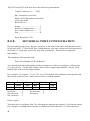
RETURNS TO THE FACTORY
67
REPACKING FOR SHIPPING
67
TECHNICAL SUPPORT/ORDERING
68
FEDERAL COMMUNICATIONS COMMISSION RADIO
FREQUENCY INTERFACE STATEMENT*
69
INDEX
70
v
1
GENERAL INFORMATION
IMPORTANT: Please verify which specific model multiport controller
you have purchased (i.e., Type A, Type AC11, Type ES, etc.). Please see
the packing list that came with your unit for the specific model type.
There is a label on the rear panel indicating the series type. Also verify
what hardware type you have purchased (i.e., 524, 525, 528, etc.). The
hardware type is indicated on the front panel. Determine if you have
purchased any options with your unit.
NOTE: If your multiport controller has a "P" suffix at the end of the
model type, this indicates the unit is equipped with non-volatile memory
and will be referred as a programmable unit. If you change any factory
default settings via the menu-driven configuration mode, the changes will
be retained if power is lost. When a specific item in this manual applies to
both programmable and non-programmable units, we will denote the
model type with "(P)" (e.g., 524A(P), 528ES(P)).
NOTE: If your multiport controller does not have a label on the back
panel indicating the series type, you may assume you have purchased a
524NB(P) or 528NB(P). Please see the packing list to confirm.
The following sections apply to all models: Section 2 (Specifications),
Section 3 (Installation), Section 4 (Cabling), Section 7 (Maintenance),
Section 8 (Technical Support/Ordering), and Section 9 (FCC Statement).
You may skip subsections that do not pertain to the multiport you have
purchased. Most subsections are titled with the specific model and/or
hardware type. Please see TABLE A on the following page for a guide to
which subsections apply to specific models.
1
TABLE A - MODEL/SUBSECTION GUIDE
Model
2
Applicable Subsections
524A(P)
1.1, 5.1.1, 5.2.1, 5.3.1, 6.1, 6.6
528A
1.1, 5.1.1, 5.1.1.1, 5.2.1, 5.3.1, 6.2
528AP
1.1, 5.1.1, 5.2.2, 5.3.1, 6.3, 6.6
5218AP
1.1, 5.1.1, 5.2.2, 5.3.1, 6.3, 6.6
524AC11(P)
1.2, 5.1.2, 5.2.1, 5.3.1, 6.1, 6.6
528AC11
1.2, 5.1.2, 5.2.1, 5.3.1, 6.2
528AC11P
1.2, 5.1.2, 5.2.2, 5.3.1, 6.3, 6.6
5218AC11P
1.2, 5.1.2, 5.2.2, 5.3.1, 6.3, 6.6
5218C
1.1, 5.1.1.3, 5.2.2, 5.3.1, 6.3, 6.6
524ES(P)
1.3, 5.1.3, 5.2.1, 5.3.1, 6.1, 6.6
528ES
1.3, 5.1.3, 5.2.1, 5.3.1, 6.2
528ESP
1.3, 5.1.3, 5.2.2, 5.3.1, 6.3, 6.6
5218ESP
1.3, 5.1.3, 5.2.2, 5.3.1, 6.3, 6.6
524F(P)
1.4, 5.1.4, 5.2.1, 5.3.1, 6.1.1, 6.1.3, 6.6
525FP
1.4, 5.1.4, 5.2.3, 5.3.3, 6.4
528FP
1.4, 5.1.4, 5.2.3, 5.3.1, 6.4
5218FP
1.4, 5.1.4, 5.2.2, 5.3.1, 6.5, 6.6
524G
1.5, 5.1.5, 5.2.1, 5.3.1, 6.1, 6.6
525GP
1.5, 5.1.5, 5.2.2, 5.3.3, 6.3
528G
1.5, 5.1.5, 5.2.1, 5.3.1, 6.2
529GP
1.5, 5.1.5, 5.2.2, 5.3.3, 6.3
5218GP
1.5, 5.1.5, 5.2.2, 5.3.1, 6.3
524NB(P)
1.1, 5.1.1, 5.2.1, 5.3.2, 6.1, 6.6
528NB
1.1, 5.1.1, 5.2.1, 5.3.2, 6.2
528NBP
1.1, 5.1.1, 5.2.2, 5.3.2, 6.3, 6.6
1.1
A SERIES
The A Series multiport controllers are microprocessor-controlled units that allow one
EIA-232C serial port on a computer to access up to 17 devices on a single unit and up to
96 devices by cascading units. Separate input/output buffers and UARTS enable the user
to receive and transmit data simultaneously on all ports, and mix and match devices of
different configurations. Port selection is accomplished through software control.
The 524A(P) models have one host port and four peripheral ports. The 528A(P) models
have one host port and eight peripheral ports. The Model 5218AP has one host port and
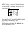
seventeen peripheral ports. Figure 1 below shows a typical application using an A Series
multiport controller.
Figure 1: A Series Application
The serial port configuration (baud rates, word size, stop bits and parity) is userselectable for each individual port on all A Series models. In addition, the control
character and XON/XOFF handshaking are programmable on the 528AP and 5218AP
models. These features are easily programmed via the menu-driven configuration mode
or by DIP switch settings (see Section 6).
NOTE: The 524NB(P) and 528NB(P) models are virtually identical to the 524A(P) and
528A(P) models except they have no buffer and pass handshake lines through the unit
(see Section 5.3.2).
NOTE: The control character and XON/XOFF handshaking are options to order (Option
2 and Option 6 respectively) on the 524A(P), 524NB(P), and 528A models if the factory
default values are not acceptable. The factory default control character is ASCII
Control-T (14 hex) and XON/XOFF handshaking is disabled from the factory.
Please contact BayTech for ordering information (See Section 8).
3
1.2
AC11 SERIES
BayTech's AC11 Series multiport controllers connect directly to a host computer and
provide multiplexing of messages from peripheral devices. Data is buffered until a
terminating character is received indicating the end of a message or until the buffer is
full. The messages are then sent to the host device preceded by a port identification
number.
The host device can select individual peripheral ports to transmit data to while
simultaneously receiving messages from all peripheral ports.
The 524AC11(P) models have one host port and four peripheral ports. The 528AC11(P)
models have one host port and eight peripheral ports. The Model 5218AC11P has one
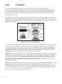
host port and seventeen peripheral ports. Figure 2 on the following page shows a typical
application using an AC11 Series multiport controller.
Figure 2: AC11 Series Application
The serial port configuration (baud rates, word size, stop bits and parity) is userselectable for each individual port on all AC11 Series models. In addition, the message
terminating character, the control character, and XON/XOFF handshaking are
programmable on the 528AC11P and 5218AC11P models. These features are easily
programmed via the menu-driven configuration mode or by DIP switch settings (see
Section 6).
NOTE: The control character and XON/XOFF handshaking are options to order (Option
2, and Option 6 respectively) on the 524AC11(P) and 528AC11 models if the factory
default values are not acceptable. The factory default control character is ASCII
Control T (14 hex) and XON/XOFF handshaking is disabled from the factory.
Please contact BayTech for ordering information (see Section 8).
4
1.3
ES SERIES
BayTech's ES Series multiplexers are designed to interface directly with a host computer
and provide automatic time-division multiplexing of data from multiple peripheral
devices thereby reducing the software overhead of the host system.
The 524ES(P) models have one host port and four peripheral ports. The 528ES(P)
models have one host port and eight peripheral ports. The Model 5218ESP has one host
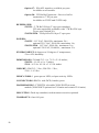
port and seventeen peripheral ports. Figure 3 below shows a typical application using an
ES Series multiport controller.
Figure 3: ES Series Application
The serial port configuration (baud rate, word size, stop bits, and parity) is user-selectable
for each individual port on all ES Series models. In addition, the data block length, the
control character, and XON/XOFF handshaking are programmable on the 528ESP and
5218ESP models. These features are easily programmed via the menu-driven
configuration mode or by DIP switch settings (see Section 6).
NOTE: The control character, and XON/XOFF handshaking are options to order
(Option 2 and Option 6 respectively) on the 524ES(P) and 528ES models if the factory
default values are not acceptable. The factory default control character is ASCII
Control-T and XON/XOFF handshaking is disabled from the factory. Please call
BayTech for ordering information (see Section 8).
5
1.4
F SERIES
The F Series multiports allow you to create a local "star" network capable of
any-port-to-any-port communication. A full duplex communication link is established
between any two connected EIA-232 ports. The 525FP and 528FP also feature a host
port control feature that will allow the host device to make or break any connection
between two devices.
The 524F(P) and 525FP models have one host port and four peripheral ports. The Model
528FP has one host port and eight peripheral ports. The Model 5218FP has one host port
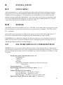
and seventeen peripheral ports. Figure 4 shows a typical application using an F Series
multiport controller.
Figure 4: F Series Application
The serial port configuration (baud rate, word size, stop bits, and parity) is user-selectable
for each individual port on all F Series models. In addition, XON/XOFF handshaking,
the output message strings, and the sign-on/sign-off character are programmable on the
525FP and 528FP models. These features are easily programmed via the menu-driven
configuration mode or by DIP switch settings (see Section 6).
NOTE: The control character and XON/XOFF handshaking are options to order (Option
2 and Option 6 respectively) for the 524F(P) and 5218FP models if the factory default
values are not acceptable. The factory default control character is ASCII Control-T
and XON/XOFF handshaking is disabled from the factory. Please see Section 8 for
ordering information.
NOTE: For all models, there is a disconnect time guard option to order (Option 7). This
option will prevent an erroneous disconnect in the case that the sign-off character
followed by a carriage return is sent as data. The disconnect time guard option requires
a two (2) second delay between the last transmitted character and the sign-off character.
Please see Section 8 for ordering information.
6
1.5
G SERIES
The G Series multiports allow a host computer device to simultaneously broadcast the
same message out to multiple peripheral ports while receiving data from an individual
selected peripheral port. The G Series multiports can also operate in a mode identical to
the A Series (i.e., a port expansion mode where the host device can individually select a
single peripheral at time to communicate with in full duplex).
The 524G and 525GP models have one host port and four peripheral ports. The 528G
and 529GP models have one host port and eight peripheral ports. The Model 5218GP has
one host port and seventeen peripheral ports. Figure 5 below shows a typical application
using a G Series multiport controller.
Figure 5: G Series Application
The serial port configuration (baud rate, word size, stop bits, and parity) are userselectable for each individual port an all G Series models. In addition, XON/XOFF
handshaking and the control character are programmable for the 525GP and 529GP
models. These features are easily programmed via the menu-driven configuration mode
or by DIP switch setting (see Section 6).
NOTE: The control character and XON/XOFF handshaking are options to order
(Options 2 and 6 respectively) on the 524G and 5218GP models if the factory default
values are not acceptable. The factory default control character is ASCII Control-T
(14 hex) and XON/XOFF handshaking is disabled from the factory. Please see
Section 8 for ordering information.
7
2
SPECIFICATIONS
INTERFACE: EIA-232C (CCITT V.24), -12v mark, +12v space. Optional
EIA-422A (Option 17) and Current Loop (Option 12).
TRANSMISSION: Asynchronous.
FACTORY-SET POWER-UP DEFAULT CONFIGURATION - ALL
MODELS EXCEPT AS NOTED:
Baud rate: 9600.
Word size: 8 bits.
Parity: None.
Stop bits: 1.
XON/XOFF: Disabled.
Control character: ^T (14 Hex).
Data block length (ES only): 32 characters.
Terminating character (AC11 Series only): Carriage
Return (0D Hex) .
Sign-On/Sign-off character (F Series only): ^T
(14 Hex).
Output Messages (F Series only):
On Line Message: ^M^JOn line^G^M^J;
Off Line Message: ^M^JOff line^M^J;
Busy Message: ^M^JBusy^M^J .
NOTE: The ^ symbol represents a control character.
USER-PROGRAMMABLE CONFIGURATION ALL MODELS EXCEPT AS NOTED:
Reconfigurable in menu-driven mode through the host port:
Port 5 of the 524 and 525 units, Port 9 of the 528 and 529
units, and Port 18 of the 5218 units. Saved in non-volatile
memory to become the new power-up default configuration
for all programmable units.
NOTE: Baud rate, word size, parity, and stop bits for the host
port of 524 and non-programmable 528 units are programmed
via DIP-switch settings.
Baud rate: 110, 135, 300, 600, 1200, 2400,
4800, 9600. 19,200 is available on 524 and 525
units only. Other rates optional.
Word size: 5, 6, 7 or 8 bits (7 or 8 bits for 524
models).
Parity: Even, odd or none.
Stop bits: 1, 1 1/2 or 2 (1 or 2 for 524 models).
XON/XOFF: Enabled or disabled (Option to
order on 524 models).
8
Contr ol character: Any code from 00 Hex to
7F Hex (option to order on 524 units).
Terminate character (528AC11P and 5218AC11P models
only): Any code from 00
Hex to 7F Hex.
Data block length (528ESP and 5218ESP models only): 1
to 250 characters.
AVAILABLE OPTIONS:
Option 2: Custom Control Character - Control
character required to select between ports. Available on all
524 models, all non-programmable 528 models, 5218FP, and
5218GP. Programmable feature on all other models.
Option 2H: Request for Message Command: ^T
followed by capital S releases a message from any one of the
peripheral ports.
Available on 524AC11P only.
Option 2I: Same Control and Configuration
Character - Single control character to switch between ports
and to configure peripheral ports.
Available on all 524 models except 524F(P). Standard feature
on all other models.
Option 3C: Custom Connectors - DTE, DB-25 male
connectors available per port.
Available on all models.
Option 4: 230 VAC power - Power supply to use 230
VAC power.
Available on all models.
Option 6: XON/XOFF Flow Control - Enables
XON/XOFF handshaking on all ports.
Available on 524AP, 524AC11P, 524ESP, 524FP, 5218FP,
and 5218GP.
Option 7: Disconnect Time Guard - With this option, a
2-second delay is required before the disconnect sequence.
Available on 524FP, 525FP, and 528FP.
Option 12: Current Loop - EIA-232 Current Loop
interface available per port. Please specify active or passive
transmit and active or passive receive. Available on all
models.
9
Option 17: EIA-422 interface available per port.
Available on all models.
Option 20: 525 Buffer Expansion - Receive buffer
expansion to 7.7K per port.
Available on 525FP and 525GP only.
BUFFER SIZE:
525/529 - 3.7K Rx/256 byte Tx per port standard;
525 units optionally available with 7.7K Rx/256 byte
Tx per port (Option 20).
524/528/5218 - 256-byte Rx/256-byte Tx per port.
POWER:
524\525 - 115 VAC, 50/60 Hz, maximum .2A.;
optional 230 VAC, 50/60 Hz, maximum .1A;
528/529/5218 - 115 VAC, 50/60 Hz., maximum .3A.;
optional 230 VAC, 50/60 Hz., maximum .2A.
ENVIRONMENT: 0 degrees to 50 degrees C temperature;
5% to 95% humidity.
DIMENSIONS: 524 and 525 - 8 x 7 1/2 x 2 1/4 inches;
528/529 - 10 1/8 x 8 x 3 inches;
5218 - 16 3/4 x 10 1/8 x 3 1/2 10 inches.
WEIGHT: 524/525 - 3 lbs.; 528/529 - 5 lbs.,
5218 - 9 1/2 lbs.
INDICATORS: 1 green power LED; red port-activity LEDs.
CONNECTORS: DB-25s with DCE (female) ports.
HANDSHAKING: CTS/DTR; selectable XON/XOFF on some
models (XON/XOFF optional on 524 units and certain 5218 units).
MOUNTING: Desk-top standard; rack-mount accessories optional.
WARRANTY: One full year.
10
3
INSTALLATION
3.1
UNPACKING
After opening the box, check the packing list that comes with your multiport to ensure
that you have received all components and to determine the specific multiport model
number you have purchased. At a minimum, you should have received the unit, this
manual, and any applicable addendums. Also check the unit to make certain that it did
not receive damage during shipping. If items are missing or damage did occur, please
contact BayTech technical support at 1-800-523-2702.
3.2
POWER
All models come with standard 115VAC, 50/60 Hz. power and a three-prong power cord.
Do not attempt to operate the unit with a two-prong socket or adapter. 230 VAC, 50/60
Hz. is optional.
All models power-up when you depress the power switch on the back of the unit to "1".
Power-on is indicated on the front panel by the illuminating of a green LED .
CAUTION: Power should be turned off anytime cables are to be installed or removed.
Make sure the power is turned off and the unit is unplugged before removing the cover
and attempting to make any internal changes.
3.3
FACTORY DEFAULT CONFIGURATION
NOTE: Before you proceed with installation, make certain that the device connected to
the host port is setup to have the same configuration as the multiport's host port. The host
port and all other ports on all series of multiports are factory configured as follows except
as noted:
Serial ports power up from the factor y at:
9600 baud rate
8 word size
1 stop bit
No parity
XON/XOFF disabled (optional for 524 units and some
5218 units)
Control character: ^T (14 Hex).
Sign-On/Sign-off character (F Series only): ^T (14
Hex).
Output Messages (F Series only):
On Line Message: ^M^JOn line^G^M^J;
Off Line Message: ^M^JOff line^M^J;
Busy Message: ^M^JBusy, no port available^M^J.
Data block length (ES Series units only): 32 characters.
11
If the factory default configuration for all ports is not satisfactory for your application,
you may then reconfigure the multiport by entering the configuration mode (see Section
6).
The controlling or host device is connected via cable to the host port on all models. This
is Port 5 of the 524 and 525 units, Port 9 of the 528 and 529 units, and Port 18 of the
5218 units.
Peripheral devices are connected via cable to any of the remaining ports. They need not
be installed in any specific order. Peripheral ports not used may be left empty.
12
4
CABLING
IMPORTANT: Before you proceed with cabling, you must know whether the devices
you are connecting to your multiport are DTE (Data Terminal Equipment) or DCE (Data
Communication Equipment). The following devices are generally DTE: terminals,
printers, and computers like the IBM PC. The following devices are DCE: modems and
some computers.
If your device transmits data on Pin 2 and receives data on Pin 3, it is DTE. If your
device receives data on Pin 2 and transmits data on Pin 3, it is DCE. However, to verify
the interface requirements for your device, please refer to the Owner's Manual for that
device.
BayTech's standard configuration of its multiports is all ports DCE with DB-25 female
connectors. DCE ports use the following signals for communication:
DCE PORT SIGNALS
Pin
EIA-232
Signal
Direction
Description
1
PGND
----
2
TX
Input
3
RX
Output
4
RTS
Input
Internally enabled if no wire connected
(normally not used).
5
CTS
Output
-12V when DCE device's buffer is full.
6
DSR
Output
+12V when DCE device powers-up.
7
SGND
----
20
DTR
Input
Protective ground
Data in
Data out
Signal ground
Transmit enabled when +12 V.
13
If you are interfacing a DCE device to a DTE device, you must use a one-to-one straight
cable as in Figure 6. If you are interfacing a DCE device to a DCE device, or a DTE
device to a DTE device, you must use a crossed cable as in Figure 7. Input handshaking
lines are enabled if nothing is connected, allowing the system to operate with only Tx, Rx
and GND connected.
500 MODEL - DCE
MALE DB-25
1
PGND
2
TXD
3
RXD
4
RTS
5
CTS
6
DSR
7
SGND
8
DCD
20
DTR
DTE DEVICE
FEMALE DB-25
<
>
1
TXD
2
RXD
3
RTS
4
>
CTS
5
>
DSR
6
SGND
7
DCD
8
DTR
20
<
>
<
PGND
Figure 6 - 500 Series (DCE) to DTE Device
500 MODEL - DCE
MALE DB-25
1
PGND
2
TXD
3
RXD
4
RTS
5
DCE DEVICE
FEMALE DB-25
PGND
< TXD
RXD
3
<
< RTS
4
CTS
CTS
5
6
DSR
DSR
6
7
SGND
SGND
7
20
DTR
<
< DTR
Figure 7 - 500 Series (DCE) to DCE Device
14
1
<
2
20
5
OPERATION
BayTech's A, AC11, ES, F, and G Series are user-programmable, multi-function devices
that allow serial port expansion/software activated switching (A Series), message
multiplexing (AC11 Series), time division multiplexing (ES Series), star networking (F
Series), and message broadcasting (G Series).
The A, AC11, ES, F, and G Series are ideal for adapting small computers like the IBM
PC to industrial process control and data gathering applications.
5.1
OPERATING PROCEDURE
5.1.1
A SERIES
BayTech's A-series multiport controllers are designed for those computer system
applications requiring serial port expansion. These are code-activated, switching devices
that increase input/output capabilities by interfacing EIA-232C peripheral devices to a
single port on a computer device.
An A-model has one host or common controlling port and either 4, 8 or 17 peripheral
ports. The host port is usually connected to a computer, and the peripheral ports are
usually connected to devices such as printers, modems, terminals, cash registers, digital
instruments, bar code readers, digital scales, numerical machines, etc.
5.1.1.1
PERIPHERAL PORT SELECTION
To connect to a particular peripheral device, the host device sends to the multiport the
current control character (factory default is Control-T) followed by the peripheral port
number to which the desired peripheral device is connected. This is a one-digit number
for the 524A(P) and 528A(P) and a two-digit number for the 5218AP. After receiving
the control character and the port number, the multiport will provide full duplex
communication between the host device and the selected peripheral device.
NOTE: The control character and the port number are trapped and not transmitted to the
peripheral device. If you wish to send the control character to the peripheral device, it
must be sent twice. The first control character is trapped and the second is passed
through the multiport.
Another method of passing the control character to the selected peripheral device is to
enter the binary mode of operation (see Section 5.1.1.2).
The host device and the selected peripheral device will remain connected until another
port is selected. This is accomplished by sending from the PC the control character
followed by the new port number.
When switching ports, there may be some question as to which is the last character
received from the current port and which is the first character received from the new port.
15
A way to avoid this confusion when selecting a new port is to wait two character times
between the control character and the port number. When the multiport receives control
character, it stops the transmitting of data to the host UART from the current peripheral
port. However, since the UART has some buffer, up to two characters may still be sent
to the host device. The multiport does not start loading data from the new peripheral port
into the host UART until the new port number is received.
A method of accomplishing this delay is to send a string of ASCII zeros (30 Hex)
between the control character and the new peripheral port number.
For example, suppose you are transmitting and receiving data from Port 1 of a 524A-P,
and you wish to switch to Port 2.
1.
Send from the host device the control character.
2.
Wait two character times.
3.
Read host device input buffer.
4.
If there are no characters in the host device's input
buffer, send ASCII "2". This will switch the host
device to Port 2. If there are characters in the host
device's input buffer (which come from Port 1), you
may send ASCII "1" to continue communicating with
Port 1 or "2" to switch to Port 2. Any characters
received after sending the new port number will be
from the new port.
NOTE: When looking for a control character, the multiport masks the 8th or parity bit.
Therefore, either Control-T with parity bit off (14 Hex) or ^T with parity bit on (94 Hex)
will appear the same (assuming the factory default control character is used).
5.1.1.2
BINARY MODE
NOTE: Only the 528AP and 528NBP models support binary mode.
The binary mode allows all data entered through the host port, including the control
character, to be transparent to the multiport and passed through to the peripheral device.
Note that in both the normal and binary modes, data is transparent in the opposite
direction - from a peripheral device to the host device.
To access the binary mode, send through the host port Control-T (or the current control
character) followed by ASCII capital B.
Note that while in the binary mode, the configuration mode cannot be accessed nor can
the user select a new port. The host device will remain connected to the last peripheral
port selected while in the binary mode of operation.
16
To get back to the normal mode of operation, a Break condition must be detected by the
host port of the multiport.
5.1.1.3
CASCADING - THE MODEL 5218C
The Model 5218C is a cascading unit allowing a single user to access up to 96 peripheral
ports.
Ports 1 through 16 operate the same as a basic Model 5218AP. Port 17 is the cascading
port and is hooked to Port 18 of the next cascaded unit. Port 18, the host port, of the first
unit is connected to the host device.
To select any port up to 96, the user sends the control character (Control-T) followed by
the desired port number (01 to 96). The host port will examine the port number. If is 16
or less, that port will be selected. If it is greater than 16, the cascaded multiport will
subtract 16 and transmit Control-T and the remainder of the port number onto the next
cascaded unit.
For example, if the host port receives a Control-T followed by a "34", the first multiport
subtracts 16 and transmits Control-T followed by an "18" to the second multiport. The
second multiport subtracts 16 and transmits Control-T followed by "2" to the third
multiport. The third multiport connects to Port 2.
After a port has been selected and the user wishes to be connected to another port, he
sends Control-T to the host port of the first cascaded unit. If that unit is connected to Port
17, it will pass the Control-T through with no further action until it reaches a unit that is
not connected to Port 17. That unit will disconnect its host UART from the input port.
The user must now wait until all data has been transmitted to the host device prior to
sending the new port number. This allows the cascading multiports to clear all data from
their buffers and UARTs. Once all buffers are clear, the user may send the new port
number.
NOTE: If any characters are in the transmit buffers when the Control-T is sent, the
Control-T is stacked behind these characters and will not disconnect until all data has
been transmitted through.
5.1.2
AC11 SERIES
The AC11 models allow communication by interfacing a single port on a computer to 4,
8 or 17 EIA-232C serial peripheral devices. They provide multiplexing to the host port
of messages from all peripheral ports. These units also allow the host port to select and
send data to individual peripheral ports
The host or common port is usually connected to a computer, and the peripheral ports are
usually connected to devices such as cash registers, digital instruments, bar code readers,
digital scales, numerical machines, printers, modems, terminals, etc.
17
To transmit data from the host device to a peripheral device, send the control character
followed by the desired port number (single-digit number for the 524AC11(P) and
528AC11(P); two-digit number for the 5218AC11). The host device remains connected
to that peripheral device for communication until another device is selected.
The control character and the port number are trapped and, therefore, not transmitted to
the peripheral device. If you wish to send the control character to the peripheral device,
you must send it twice. The first control character is trapped; the second is passed
through the multiport.
The 8th or parity bit is masked from the control character before it is examined, allowing
you to send the control character with odd or even parity. Therefore, in a binary mode,
when 8 data bits are being sent, a 94 Hex will appear as a control character and must be
sent twice to pass through the multiport (assuming the factory default value is used).
Data received from the peripheral devices is treated as a message. A message begins
when a peripheral port receives a character and is completed when a terminating
character (factory set to Carriage Return) is received or when the buffer is full. Either
condition will cause data to be transferred to the host device a message at a time, with the
multiport inserting the port number as the first character of the message for port
identification.
Messages will be sent to the host device in a round-robin fashion (i.e., if the multiport is
sending a message from Port 1, Port 2 will be examined next for a complete message,
then Port 3, etc.).
5.1.3
ES SERIES
The ES Series provides time-division multiplexing.
The internal processor continuously scans all peripheral ports checking for characters in
the receive buffers. If a receive buffer contains characters, the data is transmitted through
the host port preceded by a port identification code (the current control character
followed by the port number).
Transmission continues until the buffer is empty or until a user-defined maximum data
block length has been transmitted. After transmission is completed, the multiport will
continue its scanning sequence.
If the current control character is received by the multiport from a peripheral device, a
second control character is added automatically. This technique allows you to detect the
control character as a data character when it is sent through the multiport.
NOTE: Transmitting and receiving of data is totally independent. Therefore, the
multiport may be receiving data on any port regardless of which port is transmitting.
To transmit data from the host device to a peripheral device, send the control character
followed by the desired port number (single-digit number for the 524ESP and 528ES;
18
two-digit number for the 5218ES). The host device remains connected to that peripheral
device with communication until another device is selected.
NOTE: The control character and the port number are trapped and not transmitted to the
selected peripheral device. If you wish to send the control character to the peripheral
device, you must send it twice. The first control character is trapped; the second is
passed through the multiport.
When looking for a control character, the multiport masks the 8th or parity bit.
Therefore, either Control-T with parity bit off (14 Hex) or Control-T with parity bit on
(94 Hex) will appear the same (assuming the factory default control character is used).
The 94 Hex must still be sent twice by the host device to enable one 94 Hex to be sent out
to the connected peripheral port.
5.1.4
F SERIES
Any of the ports on the F-Series multiport may have full duplex communication with any
one of the other ports. With the 524F(P) and the 525FP, as many as two pairs of ports
may be communicating simultaneously. With the 528FP, as many as four pairs of ports
may be communicating simultaneously. The 5218FP will allow up to nine pairs of ports
to communicate simultaneously.
A connection between two ports may be initiated by either device that wishes to
communicate. Either device must send the sign-on character (factory default is ControlT) followed by the desired port number. An On Line message is sent back to the device
requesting connection. The connection will remain until a sign-off request is received by
the multiport by either device.
If a device requests a connection and the desired port is busy, a Busy message is sent back
to the requesting device.
Disconnection may be accomplished by either of the two connected devices. The device
requesting disconnection sends to the multiport the sign-off character (factory default is
Control-T) followed by Carriage Return. An Off line message is sent back to the device
requesting disconnection.
A Disconnect Time Guard option (Option 7) is available to prevent erroneous
disconnections in case the sign-off character is transmitted as data. The disconnect time
guard requires a delay of two seconds before the sign-off character and Carriage Return
are sent.
In addition, the 525FP and the 528FP feature host port control in which the host device
(the device connected to the host port - Port 5 on the 525FP, Port 9 on the 528FP) may
also connect or disconnect between other ports at any time.
To make a connection between two ports, the host device sends to the multiport through
the host port the current sign-on character followed by ASCII capital T and the two port
19
numbers. For example, if the host device wishes to connect Ports 2 and 5, it would send
the current sign-on character followed by T25.
To force two ports to disconnect, the host device sends to the multiport through the host
port the current sign-off character followed by ASCII capital D and the two port
numbers.
NOTE: When the host device has initiated a connection, the connected devices make
also break the connection themselves by following the standard disconnect procedure.
If any non-connected device wishes to review the connection status of all ports, it may
send the current sign-on character followed by ASCII capital S. The multiport will
respond with a graphic similar to the following depicting port connection. Note that "N"
equals no connection.
Port
Connect
5.1.5
1 2 3 4 5
2 1 N 5 4
G SERIES
The G Series units power-up in the broadcast mode. Any data received by the host port is
transmitted to all of the peripheral port buffers simultaneously. In the other direction,
only one peripheral port can send data to the host port.
To operate properly in the broadcast mode, it is recommended that all ports have the
same baud rate, word size, stop bits and parity. If the baud rates on the peripheral ports
need to be different, have the host device select the peripheral port with the slowest baud
rate so no transmitted characters will be lost. Or, limit the number of characters you
transmit at one time to 240, then delay before sending more characters.
The host device may select which port it will receive data from (power-up default is Port
1). The selected port is indicated by the red LED that is lit under the corresponding port
number.
For the host device to select a peripheral port, it must send Control-T (or current control
character) followed by the desired port number (single digit for the 524G, 525GP, 528G,
and 529GP, and a double digit number for the 5218GP). Any data received by this port
will be transmitted to the host device.
The host device may instruct the G Series multiport to enter into a non-broadcast mode.
In this mode, the unit operates identically to an A Series unit (see Section 5.1.1).
To enter the non-broadcast mode, send a Control-T (or current control character)
followed by the capital letter M.
To exit the non-broadcast mode and return to the broadcast mode, send a Control-T (or
current control character) followed by the capital letter O.
20
5.2
USER-PROGRAMMABLE OPERATIONS
5.2.1
ALL 524 AND NON-PROGRAMMABLE 528
MODELS
The multiport will translate for devices using different configurations, allowing you to
mix-and-match devices of different configurations. You may set the baud rate, word size,
stop bits, and parity for each individual port.
Factory default configuration on all ports is 9600 baud rate, 8 bit word size, 1 stop
bit and no parity.
NOTE: The serial port parameters for the host port is configured via DIP-switches (baud
rate, word size, stop bits, and parity; please see Section 6.1.1). The peripheral ports are
software programmable from the host port (see Sections 6.1.2 and 6.2.2). The baud rate
for the peripheral ports of non-programmable 528 models may be set via DIP switch.
5.2.2
ALL 525, 528, 529, AND 5218 MODELS
(EXCEPT 525FP AND 528FP)
5.2.2.1
THE SERIAL PORT CONFIGURATION
The multiport will translate for devices using different configurations, allowing you to
mix-and-match devices of different configurations. You may set the baud rate, word size,
stop bits, parity, and XON/XOFF handshaking for each individual port.
NOTE: The 5218FP and 5218GP do not support XON/XOFF handshaking as a standard
feature. You may purchase Option 6 for the 5218FP or 5218GP to enable XON/XOFF
handshaking.
Factory default configuration on all ports is 9600 baud rate, 8 bit word size, 1 stop
bit, parity, and XON/XOFF handshaking disabled.
5.2.2.2
THE CONTROL CHARACTER
To select a peripheral port, the host device sends the control character to the multiport
followed by the peripheral port number. The control character is also used to access the
configuration mode. The control character may consist of any single character from 00
Hex to 7F Hex.
NOTE: The control character is not a programmable feature for the 5218FP.
The Factory default is Control-T (14 Hex).
21
5.2.2.3
528AC11P AND 5218AC11P - THE MESSAGE
TERMINATING CHARACTER
This is a single character that indicates a completed message to the multiport for the
AC11 Series. Data is held in the buffer of the multiport until either this message
terminating character is received from the peripheral device or the buffer fills, causing the
data to be transmitted out of the host port of the multiport preceded by a port
identification number. The single message terminating character is in the form of any
two-digit hexadecimal character from 00 Hex to 7F Hex.
Factory default is Carriage Return (0D Hex).
5.2.2.4
528ESP AND 5218ESP - SET DATA BLOCK
LENGTH
The data block length is the maximum number of characters per message transmitted out
of the host port of the ES Series. You may select a data block length of 1 to 250
characters.
The factory default data block length is 32 characters.
5.2.3
525FP AND 528FP
5.2.3.1
THE SERIAL PORT CONFIGURATION
The multiport will translate for devices using different configurations, allowing you to
mix-and-match devices of different configurations. You may set the baud rate, word size,
stop bits, parity, and XON/XOFF handshaking for each individual port.
Factory default configuration on all ports is 9600 baud rate, 8 bit word size, 1 stop
bit, parity, and XON/XOFF handshaking disabled.
5.2.3.2
THE SIGN ON/SIGN OFF CHARACTER
To select a peripheral port, the host device sends the sign-on/sign-off character to the
multiport followed by the peripheral port number. The sign-on/sign-off character is also
used to access the configuration mode. The sign-on/sign-off character may consist of any
single character from 00 Hex to 7F Hex.
The Factory default is Control-T (14 Hex).
22
5.2.3.3
OUTPUT MESSAGE STRINGS
The output message strings are messages sent from the multiport to a device requesting
connection or disconnection. They include the On line message, which is sent when a
connection takes place; the Off line message, which is sent when a disconnection takes
place; and the Busy message, which is sent when the requested port is busy. The
multiport may also be programmed to send no message.
These message strings may consist of up to 32 characters maximum, entered in hex
notation or ASCII string.
Factory default on the output message strings are:
sign-on message - ^M^JOn line^G^M^J;
sign-off message - ^ M^JOff line^M^J;
busy message - ^ M^JBusy^M^J.
NOTE: The ^ symbol represents a control character. ^M gives a carriage return, ^J
gives a line feed, and ^G gives a warning bell.
5.3
DATA FLOW CONTROL
NOTE: When XON/XOFF is enabled, the multiport will continue to support hardware
handshaking lines. If this is not desired, you may disconnect the handshaking lines
entirely.
5.3.1
All 524, 528, 5218 MODELS
Host-to-multiport-to-peripheral communication
When the host device transmits data to a peripheral device through the multiport's host
port, the data is received and stored in a 256- character transmit buffer which in turn
retransmits it to a peripheral device through a peripheral port. During transmission, after
the buffer receives 236 characters, the multiport will make the host port's CTS
(Clear-To-Send) line low (negative voltage), signaling the host device that it cannot
accept more data (however, in reality it can accept another 20 characters before
overflowing the buffer).
If XON/XOFF handshaking is enabled and the host device does not respond, 8 characters
later the multiport will send an XOFF character, signaling the computer that it cannot
accept more data (however, in reality it can accept another 12 characters before
overflowing the buffer).
When the multiport's buffer empties, the multiport will make the CTS line high (positive
voltage) and send an XON character (if XON/XOFF is enabled), signaling the host
device that it can accept more data.
23
When the multiport retransmits the data to the peripheral device through a peripheral
port, and the peripheral device cannot receive any more data, the multiport will expect to
see a low on the DTR (Data Terminal Ready) line or receive an XOFF character (if
XON/XOFF is enabled). When the peripheral device can receive more data, the
multiport will expect to see a high on the DTR line or receive an XOFF character (if
XON/XOFF is enabled).
Peripheral-to-multiport-to-host communication
When a peripheral device transmits data to host device through the
multiport's peripheral port, the data is received and stored in a 256-character receive
buffer which in turn retransmits it to the computer through the host port. After the buffer
receives 236-characters, the multiport will make the peripheral port CTS (Clear-To-Send)
line low (negative voltage), signaling the peripheral device that it cannot accept more
data (however, in reality it can accept another 20 characters before overflowing the
buffer).
If XON/XOFF is enabled and the peripheral device does not respond, 8 characters later
the multiport will send an XOFF character, signaling the peripheral device that it cannot
accept more data. (However, in reality it can accept another 12 characters before
overflowing the buffer.)
When the buffer empties, the multiport will make the CTS line high (positive voltage)
and send an XON character, signaling the peripheral device that it can accept more data.
When the multiport is sending data to the host device through the host port and the host
device cannot receive any more data, the multiport will expect to see a low on the DTR
line or receive an XOFF character (if XON/XOFF is enabled).
NOTE: The Model 525FP and 528FP pass certain handshake lines through the unit. In
particular, the RTS line of a connected port is passed through to the DSR line of the other
connected port and vice-versa.
5.3.2
524NB(P) AND 528NB(P) NON-BUFFERED
UNITS
The 524NB(P) and 528NB(P) units do not have any buffer and pass data flow control
lines through the unit.
Host-to-multiport-to-peripheral communication:
When the multiport is transmitting data from the host device to a peripheral device and
the peripheral port detects a low (negative voltage) on the DTR line, the multiport will
stop transmitting data to the peripheral device In addition, the multiport will make the
host port's CTS line low and send an XOFF character (if XON/XOFF is enabled).
When the peripheral port detects a high (positive voltage) on the DTR line, the multiport
will resume transmitting data to the peripheral device. In addition, the multiport will
24
make the host port's CTS line high and send an XON character (if XON/XOFF is
enabled).
Peripheral-to-multiport-to-host communication:
When a peripheral device is transmitting data to the host device and the host port detects
a low (negative voltage) on the DTR line, the multiport will stop transmitting data to the
host device In addition, the multiport will make the peripheral port's CTS line low and
send an XOFF character (if XON/XOFF is enabled).
When the host port detects a high (positive voltage) on the DTR line, the multiport will
resume transmitting data to the host device. In addition, the multiport will make the
peripheral port's CTS line high and send an XON character (if XON/XOFF is enabled).
5.3.3
STANDARD 525/529 MODELS
Host-to-multiport-to-peripheral communication:
When the host device transmits data to a peripheral device through the multiport's host
port, the data is received and stored in a 256-character transmit buffer which in turn
retransmits it to a peripheral device through a peripheral port. During transmission, after
the buffer receives 236 characters, the multiport will make the host port CTS
(Clear-To-Send) line low (negative voltage), signaling the host device that it cannot
accept more data (however, in reality it can accept another 20 characters before
overflowing the buffer).
If XON/XOFF handshaking is enabled and the host device does not respond, 8 characters
later the multiport will send an XOFF character, signaling the computer that it cannot
accept more data (however, in reality it can accept another 12 characters before
overflowing the buffer).
When the multiport's buffer empties, the multiport will make the CTS line high (positive
voltage) and send an XOFF character (if XON/XOFF is enabled), signaling the host
device that it can accept more data.
When the multiport retransmits the data to the peripheral device through a peripheral
port, and the peripheral device cannot receive any more data, the multiport will expect to
see a low on the DTR (Data Terminal Ready) line or receive an XOFF character (if
XON/XOFF is enabled). When the peripheral device can receive more data, the
multiport will expect to see a high on the DTR line or receive an XOFF character (if
XON/XOFF is enabled).
Peripheral-to-multiport-to-host communication:
When a peripheral device transmits data to the host device through a peripheral port, the
data is received and stored in a 3740-character receive buffer (or 7740 receive buffer for
525 units with Option 20) which in turn retransmits it to the host device through the host
port. After the buffer receives 3720 characters (or 7720 characters for 525 units with
25
Option 20), the multiport will make the peripheral port CTS (Clear-To-Send) line low
(negative voltage), signaling the peripheral device that it cannot accept more data
(however, in reality it can accept another 20 characters before overflowing the buffer).
If XON/XOFF is enabled and the peripheral device does not respond, 8 characters later
the multiport will send an XOFF character, signaling the peripheral device that it cannot
accept more data. (However, in reality it can accept another 12 characters before
overflowing the buffer.)
When the buffer empties, the multiport will make the CTS line high (positive voltage)
and send an XOFF character (if XON/XOFF is enabled), signaling the peripheral device
that it can accept more data.
When the multiport is sending data to the host device through the host port and the host
device cannot receive any more data, the multiport will expect to see a low on the DTR
line or receive an XOFF character.
26
6
CONFIGURATION
NOTE: Most ports on all models may be configured via software commands by
following a menu-driven configuration procedure (verbose mode). Some models also
allow you to download a character string to configure the multiport without having to
follow configuration menus (non-verbose mode). Please see Section 6.6 for a list of
models that support non-verbose mode and instructions.
6.1
ALL 524 MODELS - CONFIGURATION
PROCEDURE
IMPORTANT: Before you proceed, you must know the configuration of the devices
that you are going to connect to your 524 unit (i.e., baud rate, word size, stop bits and
parity). For your devices to communicate properly, the configuration of each port must
match exactly the configuration of the device connected to that port.
6.1.1
HOST PORT CONFIGURATION
The host port of the 524 units are factory-configured at 9600 baud, 8 bit word size, 1 stop
bit and no parity. If the device you connect to the host port does not match this
configuration, then you may reconfigure the host port via a set of internal DIP-switches.
Use the following procedure to program the host port on 524 units:
1)
2)
3)
4)
5)
6)
Turn off the power switch and disconnect the AC power cord;
Lift the cover of your 524 unit by removing the screw in each corner;
Locate the internal DIP-switches.
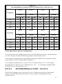
Consult Table B on the following page to determine the correct setting of the
DIP-switches.
NOTE: If Switch 6 is "on" (parity disabled), the setting of Switch 5 (parity
even or odd) will have no effect on the operation of the 524.
Replace Cover;
Host port configuration is now complete. The 524 will read the positions of the
DIP-switches upon power-up. You may now reconfigure your peripheral ports
if necessary.
27
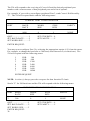
TABLE B - 524 HOST PORT DIP-SWITCH SETTINGS
Baud Rate
Switch 1
Switch 2
Switch 3
150
Off
Off
Off
300
On
Off
Off
600
On
Off
On
1200
Off
Off
On
2400
On
On
Off
4800
Off
On
Off
9600
Off
On
On
19200
On
On
On
Stop Bits
Switch 4
2
Off
1
On
Parity
Switch 5
Even
Off
Odd
On
Parity
Switch 6
Enable
Off
Disable
On
Word Size
Switch 7
8 Bits
Off
7 Bits
On
NOTE: Switch #8 has no effect on the host port's configuration.
28
6.1.2
ALL 524 MODELS EXCEPT 524F(P) PERIPHERAL PORT CONFIGURATION
To access the configuration mode of the multiport, connect a dumb terminal (or a PC
running a terminal emulation program) to the host port, Port 5 of the 524.
You may review the 524's current status by sending an ASCII Control-R followed by 0.
You may also reconfigure an individual peripheral port's serial port parameters by
sending ASCII Control-R followed by the desired peripheral port number, i.e., 1 through
4, depending on which peripheral port you want to reconfigure.
6.1.2.1
STATUS
The 524 unit will respond to the receiving of Control-R followed by 0 with a table similar
to the following which shows the current serial port configuration for the peripheral
ports:
Bay Technical Associates
Model 524 Port Expander, Rev. x.xx
Copyright 198x
CURRENT PORT CONFIGURATION
PORT
BAUD
RATE
WORD
SIZE
STOP
BITS
PARITY
1
9600
8
1
NONE
2
9600
8
1
NONE
3
9600
8
1
NONE
4
9600
8
1
NONE
If the current port configuration does not match your application, then you must
reconfigure the appropriate peripheral port as described in Section 6.1.2.2.
6.1.2.2
SET SERIAL PORT CONFIGURATION
You may reconfigure individual peripheral ports by sending ASCII Control-R followed
by the desired peripheral port number (1 through 4).
29
The 524 will respond to the receiving of Control-R and the desired peripheral port
number with a current status of that peripheral port and a list of options.
For example, if you wish to reconfigure peripheral Port 3, send Control-R followed by
"3". The 524 will respond back with the following menu:
CURRENT PORT CONFIGURATION
PORT
BAUD
RATE
WORD
SIZE
STOP
BITS
PARITY
3
9600
8
1
NONE
QUIT.........………….......1
SET BAUD RATE..….....2
SET WORD SIZE..…......3
SET STOP BITS.....4
SET PARITY......…5
ENTER REQUEST:
You may now reconfigure Port 3 by selecting the appropriate option (1-5) from the menu.
For example, to change the baud rate to 300 baud, send character 2 (set baud rate). The
524 will respond with the following menu:
1
2
3
4
5
6
7
FOR
FOR
FOR
FOR
FOR
FOR
FOR
300
600
1200
2400
4800
9600
19200
ENTER REQUEST:
NOTE: A colon (:) always precedes a request for data from the 524 unit.
Send a "1" for 300 baud rate and the 524 will respond with the following menu:
CURRENT PORT CONFIGURATION
PORT
BAUD
RATE
WORD
SIZE
STOP
BITS
PARITY
3
300
8
1
NONE
QUIT...........……….......1
SET BAUD RATE.…....2
SET WORD SIZE..........3
ENTER REQUEST:
30
SET STOP BITS.....4
SET PARITY....…..5
If there are no other changes for this port, send a "1" to exit the serial port configuration
mode for Port 3. The programmable 524s (i.e., 524s with a "P" suffix) will respond with
the following message:
Save Changes Permanently? (Y/N):
If you answer "Y" (yes), the new configuration for that port will be stored permanently in
non-volatile memory, and the multiport will subsequently power-up at the new
configuration.
If you answer "N" (no), the new configuration will be stored in RAM, and on the next
power-up, the multiport will revert to the previous configuration.
NOTE: Menu selection is case sensitive. Be sure to enter Capital Y or Capital N in
response to the prompt.
The programmable 524 will now return to the operations mode.
NOTE: Non-programmable 524s (i.e., 524s without a "P" suffix) will return to
operations mode immediately after you respond with "1" (Quit) from the Current Port
Configuration menu above.
NOTE: Please see Section 2 for a list of available options on the 524AP, 524AC11P,
and 524ESP.
6.1.3
524F(P) PERIPHERAL PORT
CONFIGURATION
To access the configuration mode of the multiport, connect a dumb terminal (or a PC
running a terminal emulation program) to the host port, Port 5 of the 524F(P).
To review the configuration of all peripheral ports on the Model 524(F), send from the
Host Port an ASCII Control-T followed by a capital "K".
To reconfigure peripheral Port 1, send a Control-T followed by an "A". To reconfigure
peripheral Port 2, send a Control-T followed by a "B". To reconfigure peripheral Port 3,
send a Control-T followed by a "C". To reconfigure peripheral Port 4, send a Control-T
followed by a "D".
6.1.3.1
STATUS
The 524F(P) will respond to the receiving of Control-T followed by capital K with a table
similar to the following which shows the current serial port configuration for the
peripheral ports:
31
Bay Technical Associates
Model 524 Port Expander, Rev. x.xx
Copyright 198x
CURRENT PORT CONFIGURATION
PORT
BAUD
RATE
WORD
SIZE
STOP
BITS
PARITY
1
9600
8
1
NONE
2
9600
8
1
NONE
3
9600
8
1
NONE
4
9600
8
1
NONE
If the current port configuration does not match your application, then you must
reconfigure the appropriate peripheral port as described in Section 6.1.3.2.
6.1.3.2
SET SERIAL PORT CONFIGURATION
You may reconfigure individual peripheral ports by sending ASCII Control-T followed
by ASCII Capital A, B, C , or D for peripheral ports 1 through 4 respectively.
The 524F(P) will respond to the receiving of Control-T and the appropriate peripheral
port letter with a current status of that peripheral port and a list of options.
For example, if you wish to reconfigure peripheral Port 3, send Control-T followed by
"C". The 524F(P) will respond back with the following menu:
CURRENT PORT CONFIGURATION
PORT
BAUD
RATE
WORD
SIZE
STOP
BITS
PARITY
3
9600
8
1
NONE
QUIT............……….....1
SET BAUD RATE........2
SET WORD SIZE.........3
ENTER REQUEST:
32
SET STOP BITS.....4
SET PARITY.....….5
You may now reconfigure Port 3 by selecting the appropriate option (1-5) from the menu.
For example, to change the baud rate to 300 baud, send character 2 (set baud rate). The
524F(P) will respond with the following menu:
1
2
3
4
5
6
7
FOR
FOR
FOR
FOR
FOR
FOR
FOR
300
600
1200
2400
4800
9600
19200
ENTER REQUEST:
NOTE: A colon (:) always precedes a request for data from the 524F(P) unit.
Send a "1" for 300 baud rate and the 524F(P) will respond with the following menu:
CURRENT PORT CONFIGURATION
PORT
BAUD
RATE
WORD
SIZE
STOP
BITS
PARITY
3
300
8
1
NONE
QUIT...........………......1
SET BAUD RATE........2
SET WORD SIZE.........3
SET STOP BITS.....4
SET PARITY..…....5
ENTER REQUEST:
If there are no other changes for this port, send a "1" to exit the serial port configuration
mode for Port 3. The 524FP will respond with the following message:
Save Changes Permanently? (Y/N):
If you answer "Y" (yes), the new configuration for that port will be stored permanently in
non-volatile memory, and the multiport will subsequently power-up at the new
configuration.
If you answer "N" (no), the new configuration will be stored in RAM, and on the next
power-up, the multiport will revert to the previous configuration.
NOTE: Menu selection is case sensitive. Be sure to enter Capital Y or Capital N in
response to the prompt.
The 524FP will now return to the operations mode.
33
NOTE: The 524F (non-programmable) will return to operations mode immediately after
entering "1" (Quit) from the Current Port Configuration menu.
NOTE: Please see Section 2 for available options on the 524F(P).
6.2
ALL 528 NON-PROGRAMMABLE MODELS
- CONFIGURATION PROCEDURE
IMPORTANT: Before you proceed, you must know the configuration of the devices
that you are going to connect to your 528 unit, i.e., baud rate, word size, stop bits and
parity. For your devices to communicate properly, the configuration of each port must
match exactly the configuration of the device connected to that port.
6.2.1
HOST PORT CONFIGURATION
The host port of the 528 units are factory-configured at 9600 baud, 8 bit word size, 1 stop
bit and no parity. If the device you connect to the host port does not match this
configuration, then you may reconfigure the host port via a set of internal DIP-switches.
Use the following procedure to program the host port on 528 units:
1)
2)
3)
4)
5)
6)
34
Turn off the power switch and disconnect the AC power cord;
Lift the cover of your 528 unit by removing the screw in each corner;
Locate the DIP-switches on the back panel. DIP switch bank A is used to
configure the host port.
Consult Table C on the following page to determine the correct settings of the
DIP-switch bank A.
NOTE: If Switch A7 is "on" (parity disabled), the setting of Switch 5 (parity
even or odd) will have no effect on the operation of the 528.
Replace Cover;
Host port configuration is now complete. The 528 will read the positions of the
DIP-switches upon power-up. You may now reconfigure your peripheral ports
if necessary.
TABLE C - 528 HOST PORT DIP-SWITCH SETTINGS
Baud Rate
Switch A1
Switch A2
Switch A3
110
Off
Off
Off
135
Off
Off
On
300
Off
On
Off
600
Off
On
On
1200
On
Off
Off
2400
On
Off
On
4800
On
On
Off
9600
On
On
On
Word Size
Switch A5
8 Bits
On
7 Bits
Off
Stop bits
Switch A6
2
On
1
Off
Parity
Switch A7
Enable
On
Disable
Off
Parity
Switch A8
Odd
Off
Even
On
35
6.2.2
PERIPHERAL PORT CONFIGURATION
The peripheral ports of the non-programmable 528 units may be configured via DIP
switch settings or by software configuration.
NOTE: Only the baud rate for the peripheral ports may be configured by DIP switch
settings. You are given four possible baud rate selections using this method: 300, 1200,
4800, and 9600. If you wish to reconfigure the baud rate to a value other than the four
specified or if you wish to change the word size, stop bits, or parity, you must use the
software method.
NOTE: If you change the baud rate for any of the peripheral port by using DIP switch
settings, the multiport will power up with those baud rates in effect. If you change any
serial port settings using the software method, the changes will be lost when the multiport
is powered off.
Peripheral Port Configuration Using DIP Switches
If you wish to reconfigure the peripheral ports using DIP switch settings, use the
following procedure:
1)
2)
3)
4)
5)
6)
36
Turn off the power switch and disconnect the AC power cord;
Lift the cover of your 528 unit by removing the screw in each corner;
Locate the DIP-switches on the back panel. DIP switch banks B and C are used
to configure the peripheral ports.
Consult Table D to determine the correct settings of the DIP-switch banks B and
C.
Replace Cover;
Peripheral port configuration is now complete. The 528 will read the positions
of the DIP-switches upon power-up.
TABLE D
528 PERIPHERAL PORT BAUD RATE DIP-SWITCH SETTINGS
Port 1
Port 2
Port 3
Port 4
Switch
Switch
Switch
Switch
Baud Rate
B1
B2
B3
B4
B5
B6
B7
B8
300
Off
Off
Off
Off
Off
Off
Off
Off
1200
Off
On
Off
On
Off
On
Off
On
4800
On
Off
On
Off
On
Off
On
Off
9600
On
On
On
On
On
On
On
On
Port 5
Port 6
Port 7
Port 8
Switch
Switch
Switch
Switch
Baud Rate
C1
C2
C3
C4
C5
C6
C7
C8
300
Off
Off
Off
Off
Off
Off
Off
Off
1200
Off
On
Off
On
Off
On
Off
On
4800
On
Off
On
Off
On
Off
On
Off
9600
On
On
On
On
On
On
On
On
528 Peripheral Port Software Configuration
To access the software configuration mode of the 528 multiport, connect a dumb terminal
(or a PC running a terminal emulation program) to the host port, Port 9.
To review the configuration of all peripheral ports on the Model 528, send from the Host
Port an ASCII Control-T followed by a capital "K".
To reconfigure peripheral Port 1, send a Control-T followed by an "A"; to reconfigure
peripheral Port 2, send a Control-T followed by a "B"; ...; to reconfigure peripheral Port
8, send a Control-T followed by a "H".
6.2.2.1
528 PERIPHERAL PORT - STATUS
The 528 will respond to the receiving of Control-T followed by capital K with a table
similar to the following which shows the current serial port configuration for the
peripheral ports:
37
Bay Technical Associates
Model 528 Port Expander, Rev. x.xx
Copyright 198x
CURRENT PORT CONFIGURATION
PORT
BAUD
RATE
WORD
SIZE
STOP
BITS
PARITY
1
9600
8
1
NONE
2
9600
8
1
NONE
3
9600
8
1
NONE
4
9600
8
1
NONE
5
9600
8
1
NONE
6
9600
8
1
NONE
7
9600
8
1
NONE
8
9600
8
1
NONE
If the current port configuration does not match your application, then you must
reconfigure the appropriate peripheral port as described in Section 6.2.2.2.
6.2.2.2
528 PERIPHERAL PORT - SET SERIAL
PORT CONFIGURATION
You may reconfigure individual peripheral ports by sending ASCII Control-T followed
by ASCII Capital A, B, C , D, E, F, G, or H for peripheral ports 1 through 8 respectively.
The 528 will respond to the receiving of Control-T and the appropriate peripheral port
letter with a current status of that peripheral port and a list of options.
For example, if you wish to reconfigure peripheral Port 3, send Control-T followed by
"C". The 528 will respond back with the following menu:
38
CURRENT PORT CONFIGURATION
PORT
BAUD
RATE
WORD
SIZE
STOP
BITS
PARITY
3
9600
8
1
NONE
QUIT....……….............1
SET BAUD RATE........2
SET WORD SIZE.........3
SET STOP BITS.....4
SET PARITY.….....5
ENTER REQUEST:
You may now reconfigure Port 3 by selecting the appropriate option (1-5) from the menu.
For example, to change the baud rate to 300 baud, send character 2 (set baud rate). The
528 will respond with the following menu:
1
2
3
4
5
6
7
8
ENTER
FOR
110
FOR
135
FOR
300
FOR
600
FOR
1200
FOR
2400
FOR
4800
FOR
9600
REQUEST:
NOTE: A colon (:) always precedes a request for data from the 528 unit.
Send a "1" for 300 baud rate and the 528 will respond with the following menu:
CURRENT PORT CONFIGURATION
PORT
BAUD
RATE
WORD
SIZE
STOP
BITS
PARITY
3
300
8
1
NONE
QUIT....……….............1
SET BAUD RATE........2
SET WORD SIZE.........3
SET STOP BITS.....4
SET PARITY…......5
ENTER REQUEST:
If there are no other changes for this port, send a "1" to exit the serial port configuration
mode for Port 3 and the 528 will now return to the operations mode.
39
6.3
ALL 525, 528(x)P, 529, AND 5218 MODELS
(EXCEPT 525FP, 528FP, AND 5218FP) CONFIGURATION PROCEDURE
All configuration changes must be made through the host port. This is Port 9 on the 528
models and Port 18 on the 5218 models.
To access the configuration mode of the multiport, connect a terminal (or a PC running a
terminal emulation program) to the host port. Send from this device the current control
character (factory default is Control-T) followed by ASCII capital C (43 Hex).
NOTE: For illustration purposes, we will use the configuration menus of the 528AP,
528AC11P, 528ESP, and 529GP.
6.3.1
528AP, 5218AP - MAIN CONFIGURATION
MENU
The multiport will respond to the receiving of the control character and capital C with an
identification block and a configuration menu of the options available, similar to the
following:
Bay Technical Associates
Model 528A Multiport Controller
Copyright 1984
Revision 2.05
Status.................................…….....1
Set Serial Port Configuration.........2
Set Control Character.....................3
Set XON/XOFF Handshaking........4
Exit .....................................………X
Enter Request:
NOTE: Menu selection is case sensitive. It is recommended that your keyboard be in the
CAPS LOCK position.
6.3.2
528AC11P, 5218AC11P - MAIN
CONFIGURATION MENU
The multiport will respond to the receiving of the control character and capital C with an
identification block and a configuration menu of the options available, similar to the
following:
40
Bay Technical Associates
Model 528AC11 Multiport Controller
Copyright 1984
Revision 2.05
Status.......................……........…........1
Set Serial Port Configuration..……....2
Set Control Character..…….........…...3
Set Message Terminate Character.......4
Set XON/XOFF Handshaking.............5
Exit .......….…......……...........….........X
Enter Request:
NOTE 1: Menu selection is case sensitive. It is recommended that your keyboard be in
the CAPS LOCK position.
NOTE 2: In the configuration mode, some characters are displayed with a Hex notation
since all combinations from 00 Hex to 7F Hex may be selected, some of which are not
printable characters.
6.3.3
528ESP, 5218ESP - MAIN CONFIGURATION
MENU
The multiport will respond to the receiving of the control character and capital C with an
identification block and a configuration menu of the options available, similar to the
following:
Bay Technical Associates
Model 528ES Multiport Controller
Copyright 1984
Revision 2.05
Status.........….…….......…......….....1
Set Serial Port Configuration...........2
Set Data Block Length.....................3
Set Control Character.......................4
Set XON/XOFF Handshaking..........5
Exit ...................………....................X
Enter Request:
NOTE 1: Menu selection is case sensitive. It is recommended that your keyboard be in
the CAPS LOCK position.
NOTE 2: In the configuration mode, some characters are displayed with a HEX notation
since all combinations from 00 Hex to 7F Hex may be selected, some of which are not
printable characters.
41
6.3.4
525GP/529GP/5218GP - MAIN
CONFIGURATION MENU
The multiport will respond to the receiving of the control character and capital C with an
identification block similar to the following and a menu of the configuration options
available:
Bay Technical Associates
Model 525G Broadcast Controller
Copyright 1986
Revision 2.01
Status...............................…......1
Set Port Configuration...............2
Set Control Character................3
Exit ..................................…......X
Enter Request(1-3,X):
6.3.5
STATUS
By responding to the Enter Request: message at the end of the main configuration menu
with "1" (Status), you may see the status of all ports and the current operation protocol.
The multiport will respond with:
Port
1
2
3
4
5
6
7
8
9
Baud
Rate
9600
9600
9600
9600
9600
9600
9600
9600
9600
Word
Size
8
8
8
8
8
8
8
8
8
Press Any Key to Continue
42
Stop
Bits
1
1
1
1
1
1
1
1
1
Pariity
None
None
None
None
None
None
None
None
None
Xon/
Xoff
Off
Off
Off
Off
Off
Off
Off
Off
Off
The 528AP and 5218AP will also show the following information:
Control Character is .......14H
XON/XOFF Handshaking is.....(Off)
Status..............................…….......1
Set Serial Port Configuration........2
Set Control Character....................3
Set XON/XOFF Handshaking…...4
Exit ...............................…….........X
Enter Request:
The 528AC11P and 5218AC11P will also show the following information:
Current Control Character is ..…...14H
Current Terminate Character is .....0DH
XON/XOFF Handshaking is..........(Off)
Status..............................…………......1
Set Serial Port Configuration......….....2
Set Control Character..................….....3
Set Message Terminate Character........4
Set XON/XOFF Handshaking..............5
Exit ............................…………...........X
Enter Request:
The 528ESP and 5218ESP will also show the following information:
Current Block Length is.....…........32
Current Control Character is ...…..14H
XON/XOFF Handshaking is..........(Off)
Status..........................………..........1
Set Serial Port Configuration...........2
Set Data Block Length.....................3
Set Control Character.......................4
Set XON/ XOFF Handshaking...…...5
Exit ..............................……….........X
Enter Request:
43
The 525G and 529G will also show the following information:
Control Character is .......14H
Bay Technical Associates
Model 525G Broadcast Controller
Copyright 1986
Revision 2.01
Status......................................1
Set Port Configuration............2
Set Control Character.............3
Exit ...................................…..X
Enter Request(1-3,X):
6.3.6
SET SERIAL PORT CONFIGURATION
By responding to the Enter Request: message at the end of the main configuration menu
of any unit with "2" (Set Serial Port Configuration), you may change the configuration of
each port (i.e. baud rate, word size, stop bits, and parity). Each port is configured
individually.
The multiport will respond with:
Enter Port Number (0=Exit),Return:
You should then enter the number of the port that you wish to reconfigure, followed by
Carriage Return. On the 528 models, this will be a single-digit number. On the 5218
models, this will be a two-digit number.
For example, if you enter "3" (or "03" on a 5218 model), the multiport will respond with
the current status of Port 3 and a menu of the available options:
Port
3
Baud
Rate
9600
Exit/Save………1
Set baud rate…...2
Set word size…..3
Word
Size
8
Stop
Bits
1
Pariity
None
Xon/
Xoff
Off
Set stop bits…..4
Set parity……..5
Enter request:
You may now reconfigure Port 3 by selecting the appropriate option (1-6) from the menu.
For example, to change the baud rate to 2400 baud, send character "2" (Set baud rate).
44
NOTE: The 525GP or 529GP will show Set XON/XOFF as an additional item (6) in the
submenu above which allows XON/XOFF handshaking to be enabled or disabled for
individual ports.
The multiport will respond with:
1
2
3
4
5
6
7
8
For
For
For
For
For
For
For
For
110
135
300
600
1200
2400
4800
9600
Enter request:
NOTE: The 525GP will a different set of baud rate options with the maximum being
19200.
Enter "6" for 2400 baud rate, and the multiport will respond with the reconfigured status
of the port and the menu of options:
Port
3
Baud
Rate
9600
Exit/Save………1
Set baud rate…...2
Set word size…..3
Word
Size
8
Stop
Bits
1
Pariity
None
Xon/
Xoff
Off
Set stop bit…..4
Set parity…….5
Enter request:
If there are no other changes for this port, enter "1" (Exit/Save), and the multiport will
respond with:
Save Changes Permanently? (Y/N):
NOTE: When changing the configuration of the host port, the multiport will also respond
with:
Change Device to NEW Configuration
Before Answering This Request.
This reminds you to make sure that the new configuration of the host port matches the
configuration of the host device. If they do not match, the multiport will be unable to
45
interpret the command, and, therefore, the user will be unable to access any multiport
function.
Change the host device's serial parameters to match the new configuration of the host
port before answering "Y" (yes) or "N" (no).
If you answer "Y" (yes), the new configuration for that port will be stored permanently in
non-volatile memory, and the multiport will subsequently power-up at the new
configuration.
If you answer "N" (no), the new configuration will be stored in RAM, and on the next
power-up, the multiport will revert to the previous configuration.
The multiport will now return to the main configuration menu.
6.3.7
SET CONTROL CHARACTER
NOTE: This section does not pertain to the 5218GP.
By responding to the Enter Request: message at the end of the main configuration menu
with "3" for the 528/5218AP or 528/5218AC11P or with "4" for the 528/5218ESP (Set
Control Character), you may user-define the control character.
CAUTION: BayTech advises you to log your new control character. If it is forgotten,
you will not be able to control the unit or access the configuration mode.
The multiport will respond with:
Current Control Character is ...............14H
Enter Control Character in Hex.............:
You may now enter the new control character that you want in Hex (00-7F Hex). For
example, if you enter "15" (Control-U), the multiport will respond with:
Current Control Character is ...............15H
Save Changes Permanently? (Y/N):
If you answer "Y" (yes), the new control character will be saved in non-volatile memory,
and the multiport will respond only to that character.
The multiport will respond with:
Are You Sure? (Y/N):
This message gives you a second chance to consider this change and reminds you to log
your new control character.
46
If you answer either question with "N" (no), the new control character will be stored in
RAM and lost upon next power-up. The multiport will return to the main configuration
menu.
6.3.8
528AC11P, 5218AC11P MODELS - SET
MESSAGE TERMINATING CHARACTER
By responding to the Enter Request: message at the end of the configuration menu for the
528AC11P or 5218AC11P with a "4" (Set Terminate Character), you may custom set the
terminating character.
The multiport will respond with:
Current Terminate Character is ............0DH
Enter Terminate Character in Hex..........:
Enter the terminating character that you wish in the form of a two-digit hexadecimal
number. The multiport will then respond with:
Save Changes Permanently? (Y/N):
If you enter a "Y", the change will be saved in non-volatile memory, and the multiport
will subsequently power-up with that terminating character in effect.
If you enter a "N" (no), the terminating character will be stored in RAM only, and on the
next power-up, the multiport will revert to the previous terminating character.
The multiport will now return to the main configuration menu (see Section 6.3.2).
6.3.9
528ESP, 5218ESP MODELS - SET DATA
BLOCK LENGTH
By responding to the Enter Request: message at the end of the main configuration menu
for the 528ESP or 5218ESP with a "3" (Set Data Block Length), you may change the
maximum length of the data block transmitted to the host device.
The multiport will respond with:
Current Block Length is ...............32
Enter Block Length (1 to 250):
Enter the number of characters that you wish as a maximum length for the data block.
The multiport will respond with:
Save Changes Permanently? (Y/N):
47
If you enter "Y" (yes), the change will be saved in non-volatile memory and the multiport
will subsequently power-up with the change(s) in effect.
If you enter "N" (no), the change will be stored in RAM, and on the next power-up, the
multiport will revert to the previous configuration.
The multiport will now return to the main configuration menu (see Section 6.3.3).
6.3.10
ALL 528/5218 AP, AC11P, ESP MODELS SET XON/XOFF HANDSHAKING
By responding to the Enter Request: message at the end of the main configuration menu
with "4" for the 528/5218AP or with "5" for the 528/5218AC11P or 528/5218ESP (Set
Xon/Xoff Handshaking), you may enable or disable XON/XOFF.
NOTE: CTS/DTR handshaking will be in effect regardless of whether XON/XOFF is
enabled or disabled.
The multiport will respond with:
Xon/Xoff handshaking is ...............(OFF)
Xon/Xoff handshaking? (Y/N):
You should enter "Y" (yes) if you want XON/XOFF handshaking enabled on all ports.
You should enter "N" (no) if you want XON/XOFF disabled on all ports.
The multiport will respond with:
Save Changes Permanently? (Y/N):
If you enter "Y" (yes), the change will be saved in non-volatile memory, and the multiport
will subsequently power-up with the change in effect.
If you enter "N" (no), the change will be stored in RAM only and will be lost upon
power-down.
The multiport will now return to the main configuration menu.
6.3.11
EXIT
By responding to the Enter Request: message at the end of the main configuration menu
with "X" (exit), you may exit the configuration mode and return to the operation mode.
48
6.4
525FP AND 528FP - CONFIGURATION
PROCEDURE
All configuration changes must be made through the host port. This is Port 5 on the
525FP and Port 9 on the 528FP.
To access the configuration mode of the multiport, connect a terminal (or a PC running a
terminal emulation program) to the host port. Send from this device the current
sign-on/sign-off character (factory default is Control-T) followed by ASCII capital C (43
Hex).
NOTE: For illustration purposes, we will use the 528FP's configuration menus. The
only differences between models is the actual number of ports shown, the title block
preceding the configuration options, and noted differences.
6.4.1
MAIN CONFIGURATION MENU
The multiport will respond to the receiving of the sign-on/sign-off character and Capital
C with an identification block and a menu of the configuration options available, similar
to the following which applies to the 528FP:
Bay Technical Associates
Model 528F Multiport Controller
Copyright 1983, 1986, 1987
Revision 2.08
Configuration status......…....1
Port configuration..................2
Output message strings..........3
Sign-on/sign-off character.....4
Exit .............................……....X
Enter request(1-4,X):
6.4.2
STATUS
By responding to the Enter Request(1-4,X): message at the end of the configuration menu
with "1" (Configuration status), you may review the current configuration of the
multiport.
Note: This status is not to be confused with the port connection status (see Section 5.1.4).
The multiport will respond with:
49
Port
1
2
3
4
5
6
7
8
9
Baud
Rate
9600
9600
9600
9600
9600
9600
9600
9600
9600
Word
Size
8
8
8
8
8
8
8
8
8
Stop
Bits
1
1
1
1
1
1
1
1
1
Pariity
None
None
None
None
None
None
None
None
None
Xon/
Xoff
Off
Off
Off
Off
Off
Off
Off
Off
Off
Hit any key to continue
Current Sign-on/sign-off character is: 14H
Output messages
On-line message : ^M^JOn line^G^M^J
Off-line message: ^M^JOff line^M^J
Busy message : ^M^JBusy^M^J
Hit any key to continue
Configuration status..……....1
Port configuration.......……...2
Output message strings…......3
Sign-on/sign-off character….4
Exit ...........………….............X
Enter request(1-4,X):
You may now make whatever changes are necessary by responding to the above menu.
The Exit function will return you to the Operations mode.
6.4.3
PORT CONFIGURATION
By responding to the Enter Request(1-4,X): message at the end of the configuration menu
with "2" (Port configuration), you may change the baud rate, word size, stop bits and
parity and also enable or disable XON/XOFF for each port. Each port is configured
individually, allowing the user to mix devices of different configurations.
The multiport will respond with:
Enter the port number(0-9,X):
Enter the number of the port that you wish to reconfigure, followed by Carriage Return.
If you enter "0" (zero), you may review the configuration status of all ports.
50
If, for example, you entered "3" and Carriage Return, the multiport will respond with the
current configuration status of Port 3 and a menu of the available options:
Baud
Rate
9600
Word
Size
8
Port
1
Exit/Save………..1
Set Baud rate……2
Set Word Size…..3
Stop
Bits
1
Pariity
None
Xon/
Xoff
Off
Set Stop Bits……...4
Set Parity…………5
Set XON/XOFF…..6
Enter request:
You may now reconfigure Port 3 by selecting the appropriate option (1-6) from the menu.
For example, to change the baud rate to 2400 baud, send character "2" (Set baud rate).
The multiport will respond with this menu:
1
2
3
4
5
6
7
8
For
For
For
For
For
For
For
For
110
135
300
600
1200
2400
4800
9600
Enter:
NOTE: If you are configuring a 525FP, this configuration menu will show different
choices for baud rates with 19,200 being the maximum. Please see Section 2 for a list of
supported baud rates for the 525FP.
Send "6" for 2400 baud rate, and the multiport will respond with the reconfigured status
of the port:
Port
1
Baud
Rate
9600
Word
Size
8
Stop
Bits
1
Pariity
None
Xon/
Xoff
Off
Exit/Save......1 Set Stop Bits....4
Set Baud rate..2 Set Parity.......5
Set Word size..3 Set XON/XOFF.....6
Enter request:
You may now proceed to make whatever other changes are necessary for Port 3.
51
If there are no other changes for this port, send " 1" (Exit/Save), and the multiport will
respond with:
Save permanently? (Y/N):
NOTE: When changing the configuration of the host port, the multiport will also respond
with:
Change Host Device to NEW Configuration
Before Answering This Request.
Change the host device's serial parameters to match the new configuration of the host
port before answering "Y" (yes) or "N" (no).
If you answer the Save permanently? (Y/N): prompt with "Y" (yes), the new configuration
for that port will be stored permanently in non-volatile memory, and the multiport will
subsequently power-up at that configuration.
If you answer "N" (no), the new configuration will be stored in RAM, and on the next
power-up, the multiport will revert to the previous configuration.
The multiport will now return to the main configuration menu (see Section 6.4.1).
6.4.4
OUTPUT MESSAGE STRINGS
By responding to the Enter request(1-4,X): message at the end of the configuration menu
with "3" (Output message strings), you may change the on-line, off-line and busy
messages that the multiport sends to a device.
The multiport will respond with:
On line message...….......1
Off line message..….......2
Busy message….....…....3
Return to main menu......X
Enter request(1-3,X):
NOTE: The "On line" message indicates the message sent from the multiport to a
device requesting connection. The "Off line" message indicates the message sent from
the multiport to a device requesting disconnection. The "Busy" message indicates the
message sent from the multiport to a device requesting connection when the requested
port is busy.
52
Enter the number (1-3) of the message that you wish to change.
For example, if you enter "1" (On line message), the multiport will respond with:
Current message: ^M^JOn line^G^M^J
Modify (Y/N)? :
NOTE: The ^ symbol represents a control character. ^M or OD Hex indicates line feed.
^J or 0A Hex indicates carriage return. ^G or 07 Hex indicates a warning bell.
If you enter a "N" (no), the current message will be retained, and the multiport will return
you to the Output Message Strings menu.
If you enter a "Y" (yes), the multiport will respond with:
Enter characters in hex notation or by an ASCII string
(32 characters maximum, 00H-FEH, FFH-End or 'string'):
Current character: ODH
Enter character or string:
The multiport will prompt you character by character until the message is completed.
Enter the character or string that you wish. Characters may be entered by sending two
ASCII Hex characters (00-FF Hex), followed by a Carriage Return. A string may also
be entered, but it must be delimited by apostrophes at the beginning and at the end of the
string, followed by a Carriage Return.
NOTE: If you wish to have no message sent, enter an FF Hex only, which programs no
characters into that message.
When you are finished, you must enter FF Hex to terminate the configuration of the
on-line message. The multiport will respond with:
Save permanently? (Y/N):
If you enter "Y" (yes), the new message will be saved in non-volatile memory, and the
multiport will subsequently power-up with the new message in effect.
If you enter "N" (no), the new message will be stored in RAM, and on the next power-up,
the multiport will revert to the previous message.
The multiport will then return you to the Output Message Strings menu. If you wish to
change another message, answer the Enter request (1-3,X): prompt with the appropriate
number. If you do not wish to make additional changes, enter an "X" (Return to main
menu), and the multiport will return you to the main configuration menu (see Section
6.4.1).
53
6.4.5
SIGN ON/SIGN OFF CHARACTER
By responding to the Enter request(1-4, X): message at the end of the configuration menu
with a "4" (Sign-on/sign-off character), you may change the sign-on/sign-off character to
a user-defined character.
The multiport will respond with:
Current Sign-on/Sign-off character is: 14H
Modify (Y/N)? :
If you enter a "N" (no), the current sign-on/sign-off character will be retained, and the
multiport will return to the main configuration menu (see Section 6.4.1).
If you enter a "Y" (yes), the multiport will respond with:
Remember, sign-off als o requires a carriage return
to complete the disconnect sequence.
Enter the new character in hex format(00H-7FH):
Enter the new sign-on/sign-off character that you want in hex. Any single-digit character
from 01 Hex to 7F Hex may be selected. The multiport will respond with:
Save permanently? (Y/N):
CAUTION: BayTech advises you to log your new sign-on/sign-off character. If it is
forgotten, you will be unable to control the unit or access the configuration mode.
SIGN-ON/SIGN-OFF CHARACTER_____________DATE_______BY______
SIGN-ON/SIGN-OFF CHARACTER_____________DATE_______BY______
SIGN-ON/SIGN-OFF CHARACTER_____________DATE_______BY______
If you enter "Y" (yes), the new sign-on/sign-off character will be saved in non-volatile
memory, and the multiport will subsequently respond to that character only.
If you enter "N" (no), the new sign-on/sign-off character will be stored in RAM, and on
the next power-up, the multiport will revert to the previous sign-on/sign-off character.
The multiport will now return to the main configuration menu (see Section 6.4.1).
6.4.6
EXIT
To exit the configuration mode, send an "X", and the multiport will return to the
operating mode.
54
6.5
5218FP CONFIGURATION PROCEDURE
All configuration changes must be made through the host port. This is Port 18.
To access the configuration mode of the multiport, connect a terminal (or a PC running a
terminal emulation program) to the host port. To review the configuration status of all
ports, send from this device ASCII Control-T (14 Hex), capital C, followed by 00. To
reconfigure a particular port, send ASCII Control-T, capital C, followed by the desired
peripheral port number (01 to 18).
6.5.1
5218FP - STATUS
The 5218FP will respond to the receiving of Control-T, capital C, and 00 from the host
device with the following menu:
Bay Technical Associates
Model 5128F Network Controller
Copyright 1983
Revision 2.03
PORT
1
2
3
4
5
6
7
8
9
10
11
12
13
14
15
16
17
18
BAUD RATE
9600
9600
9600
9600
9600
9600
9600
9600
9600
9600
9600
9600
9600
9600
9600
9600
9600
9600
6.5.2
WORD SIZE
8
8
8
8
8
8
8
8
8
8
8
8
8
8
8
8
8
8
STOP BITS
1
1
1
1
1
1
1
1
1
1
1
1
1
1
1
1
1
1
PARITY
NONE
NONE
NONE
NONE
NONE
NONE
NONE
NONE
NONE
NONE
NONE
NONE
NONE
NONE
NONE
NONE
NONE
NONE
5218FP - SERIAL PORT CONFIGURATION
You may reconfigure individual peripheral ports by sending ASCII Control-T (14 Hex),
capital C, followed by a two-digit port number (01 to 18).
55
The 5218FP will respond to the receiving of Control-T, capital C, and the appropriate
port number with a current status of that peripheral port and a list of options.
For example, if you wish to reconfigure peripheral Port 3, send Control-T, C, followed
by 03. The 5218FP will respond back with the following menu:
CURRENT PORT CONFIGURATION
PORT
BAUD
RATE
WORD
SIZE
STOP
BITS
PARITY
3
9600
8
1
NONE
QUIT………………..1
SET BAUD RATE… .2
SET WORD SIZE…..3
SET STOP BITS.....4
SET PARITY...…...5
ENTER REQUEST:
You may now reconfigure Port 3 by selecting the appropriate option (1-5) from the menu.
For example, to change the baud rate to 300 baud, send character 2 (set baud rate). The
5218FP will respond with the following menu:
1
2
3
4
5
6
7
8
FOR
FOR
FOR
FOR
FOR
FOR
FOR
FOR
110
135
300
600
1200
2400
4800
9600
ENTER REQUEST:
NOTE: A colon (:) always precedes a request for data from the 5218FP unit.
Send a "3" for 300 baud rate and the 5218FP will respond with the following menu:
56
CURRENT PORT CONFIGURATION
PORT
BAUD
RATE
WORD
SIZE
STOP
BITS
PARITY
3
300
8
1
NONE
QUIT.............……….....1
SET BAUD RATE.........2
SET WORD SIZE..........3
SET STOP BITS.....4
SET PARITY....…..5
ENTER REQUEST:
If there are no other changes for this port, send a "1" to exit the serial port configuration
mode for Port 3. The 5218FP will respond with the following message:
Save Changes Permanently? (Y/N):
NOTE: When changing the configuration of the host port, the multiport will also respond
with:
Change Host Device to NEW Configuration
Before Answering This Request.
Change the host device's serial parameters to match the new configuration of the host
port before answering "Y" (yes) or "N" (no).
If you answer "Y" (yes), the new configuration for that port will be stored permanently in
non-volatile memory, and the multiport will subsequently power-up at the new
configuration.
If you answer "N" (no), the new configuration will be stored in RAM, and on the next
power-up, the multiport will revert to the previous configuration.
NOTE: Menu selection is case sensitive. Be sure to enter Capital Y or Capital N in
response to the prompt.
The 5218FP will now return to the operations mode.
6.6
NON-VERBOSE MODE
Multiports power-up in the verbose or menu-driven mode. Only in the menu-driven
mode can changes be saved permanently in non-volatile memory.
The non-verbose mode, however, may be preferable in some instances. When
configuring a multiport using non-verbose mode, no menus are sent from the multiport
which allows you to program the unit by downloading an ASCII character string. This
mode applies only to configuration and does not affect operations.
57
NOTE: Changes made using non-verbose mode are not saved in non-volatile memory
and will be lost upon power-down, whereupon the power-up default configuration will
again be in effect.
The following models support non-verbose mode: 524x(P), 524F(P), 524G, 528G, all
528x(P) units (x = A, AC11, ES, or NB), 5218AP, 5218AC11P, 5218ESP, and the
5218FP.
6.6.1
ALL 524 MODELS EXCEPT 524F(P) NON-VERBOSE MODE CONFIGURATION
PROCEDURE
For these models, non-verbose mode is selected by sending ASCII Control-R followed by
"5" to the host port. Your ASCII character string would start off with: ^R5^RX<...>,
where ^R represents Control-R, X is the number of the port (1 to 4) you wish to
configure, and ... indicates the remainder of your character string which would consist of
choices selected from the following menus:
A. MAIN MENU
Quit....................................1
Set Baud Rate....................2
Set Word Size....................3
Set Stop Bits......................4
Set Parity...........................5
Exit ....................................X
B. SET BAUD RATE MENU
300..................1
600..................2
1200................3
2400................4
4800................5
9600................6
19200..............7
C) SET WORD SIZE MENU
5....................1
6....................2
7....................3
8....................4
D) SET STOP BITS MENU
1....................1
1 1/2..............2
2....................3
58
E) SET PARITY MENU
None.................1
Even.................2
Odd..................3
To return to the verbose mode, send the multiport Control-R followed by ASCII "6". If
no other changes are needed, you may begin operations with your multiport controller.
Please see Section 6.6.6 for an example using non-verbose mode.
6.6.2
524F(P) - NON-VERBOSE MODE
CONFIGURATION PROCEDURE
Non-verbose mode for the 524F(P) is selected by sending ASCII Control-T followed by
capital I. Your ASCII character string would start off with: ^TI^TX<...>, where ^T
represents Control-T, X is the letter corresponding to the desired peripheral port (A to D
for Port 1 to Port 4) and ... indicates the remainder of your character string which would
consist of choices selected from the menus shown on the previous page.
To return to the verbose mode, send the multiport ASCII Control-T followed by capital J.
If no other changes are needed, you may begin operations with your multiport controller.
Please see Section 6.6.6 for an example using non-verbose mode.
6.6.3
ALL NON-PROGRAMMABLE 528 MODELS
Non-verbose mode for all non-programmable 528 models is selected by sending ASCII
Control-T followed by capital I. Your ASCII character string would start off with:
^TI^TX<...>, where ^T represents Control-T, X is the letter corresponding to the desired
peripheral port (A to H for Port 1 to Port 8) and ... indicates the remainder of your
character string which would consist of choices selected from the following menus:
A. MAIN MENU
Quit....................................1
Set Baud Rate....................2
Set Word Size....................3
Set Stop Bits......................4
Set Parity...........................5
Exit ....................................X
59
B. SET BAUD RATE MENU
135..................1
150..................2
300..................3
600..................4
1200................5
2400................6
4800................7
9600................8
C) SET WORD SIZE MENU
5....................1
6....................2
7....................3
8....................4
D) SET STOP BITS MENU
1....................1
1 1/2..............2
2....................3
E) SET PARITY MENU
None………….1
Even…………..2
Odd.…...............3
To return to the verbose mode, send the multiport ASCII Control-T followed by capital J.
If no other changes are needed, you may begin operations with your multiport controller.
Please see Section 6.6.6 for an example using non-verbose mode.
6.6.4
ALL 528 AP, AC11P, ESP, AND NBP
MODELS - NON-VERBOSE MODE
CONFIGURATION PROCEDURE
Non-verbose mode for these models is selected by sending ASCII Control-T followed by
capital I. Your ASCII character string would start off with: ^TI^TC<...>, where ^T
represents Control-T and ... indicates the remainder of your character string which would
consist of choices selected from the menus shown in the following subsections:
6.6.4.1
528AP, 528NBP, 5218AP - NON-VERBOSE
MODE CONFIGURATION MENUS
Refer to the following menus to configure the 528AP, 528NBP, or 5218AP when using
non-verbose mode.
60
A. MAIN MENU
Status..................………….......1
Set Serial Port Configuration....2
Set Control Character.......….....3
Set Xon/Xoff Handshaking.......4
Exit ..........................…………..X
B. SET SERIAL PORT CONFIGURATION MENU
Enter port number.
Exit/Save.....................………...1
Set baud rate..................……….2
Set word size.................……….3
Set stop bits.................………...4
Set parity....................………....5
a) SET BAUD RATE MENU
110..................1
135..................2
300..................3
600..................4
1200................5
2400................6
4800................7
9600................8
b) SET WORD SIZE MENU
5....................1
6....................2
7....................3
8....................4
c) SET STOP BITS MENU
1....................1
1 1/2..............2
2....................3
d) SET PARITY MENU
None................1
Even.................2
Odd..................3
C. SET CONTROL CHARACTER
Enter control character in HEX.
D. SET XON/XOFF HANDSHAKING
Xon/Xoff Handshaking? (Y/N)
61
To return to the verbose mode, send the multiport ASCII Control-T (or current control
character) followed by capital "J". If no other changes are needed, you may begin
operations with your multiport controller.
Please see Section 6.6.6 for an example using non-verbose mode.
6.6.4.2
528AC11P, 5218AC11P - NON-VERBOSE
MODE CONFIGURATION MENUS
Refer to the following menus to configure the 528AC11P or 5218AC11P when using
non-verbose mode.
A. MAIN MENU
Status.............…………..........……1
Set Serial Port Configuration.…….2
Set Control Character..………........3
Set Message Terminate Character...4
Set Xon/Xoff Handshaking......…...5
Exit .......................…………….......X
B. SET SERIAL PORT CONFIGURATION MENU
Enter port number.
Exit/Save......................1
Set baud rate.................2
Set word size................3
Set stop bits ..................4
Set parity......................5
a) SET BAUD RATE MENU
110..................1
135..................2
300..................3
600..................4
1200................5
2400................6
4800................7
9600................8
b) SET WORD SIZE MENU
5....................1
6....................2
7....................3
8....................4
62
c) SET STOP BITS MENU
1...................1
1 1/2.............2
2...................3
d) SET PARITY MENU
None................1
Even.................2
Odd..................3
C. SET CONTROL CHARACTER
Enter control character in HEX (2-digit).
D. SET MESSAGE TERMINATE CHARACTER
Enter message terminate character in HEX (2-digit).
E. SET XON/XOFF HANDSHAKING
Xon/Xoff Handshaking? (Y/N)
To return to the verbose mode, send the multiport ASCII Control-T (or current control
character) followed by capital "J". If no other changes are needed, you may begin
operations with your multiport controller.
Please see Section 6.6.6 for an example using non-verbose mode.
6.6.4.3
528ESP, 5218ESP - NON-VERBOSE MODE
CONFIGURATION MENUS
Refer to the following menus to configure the 528ESP or 5218ESP when using nonverbose mode.
A. MAIN MENU
Status.......................…………...1
Set Serial Port Configuration.….2
Set Data Block Length.......….....3
Set Control Character.....….…....4
Set Xon/Xoff Handshaking.........5
Exit ................…………..............X
B. SET SERIAL PORT CONFIGURATION MENU
Enter port number.
Exit/Save........................1
Set baud rate...................2
Set word size..................3
Set stop bits .......….........4
Set parity............…........5
63
a) SET BAUD RATE MENU
110..................1
135..................2
300..................3
600..................4
1200................5
2400................6
4800................7
9600....…........8
b) SET WORD SIZE MENU
5....................1
6....................2
7....................3
8....................4
c) SET STOP BITS MENU
1....................1
1 1/2..............2
2....................3
d) SET PARITY MENU
None................1
Even.................2
Odd..................3
C. SET DATA BLOCK LENGTH
Enter desired data block length (1 to 250 characters). Insert Carriage
Return if less that three digits are entered.
D. SET CONTROL CHARACTER
Enter control character in HEX (2-digit).
E. SET XON/XOFF HANDSHAKING
Xon/Xoff Handshaking? (Y/N)
To return to the verbose mode, send the multiport ASCII Control-T (or current control
character) followed by capital "J". If no other changes are needed, you may begin
operations with your multiport controller.
Please see Section 6.6.6 for an example using non-verbose mode.
6.6.5
5218FP - NON-VERBOSE CONFIGURATION
PROCEDURE
Non-verbose mode for the 5218FP is selected by sending ASCII Control-T followed by
capital I. Your ASCII character string would start off with: ^TI^TCXX<...>, where ^T
represents Control-T, XX represents the desired port number (01 to 18), and ... indicates
64
the remainder of your character string which would consist of choices selected from the
following menus:
A. MAIN MENU
Quit....................................1
Set Baud Rate....................2
Set Word Size....................3
Set Stop Bits......................4
Set Parity...........................5
B. SET BAUD RATE
110.....................................1
135.....................................2
300.....................................3
600.....................................4
1200...................................5
2400...................................6
4800...................................7
9600...................................8
C. SET WORD SIZE
5.......................................1
6.......................................2
7.......................................3
8.......................................4
D. SET STOP BITS
1.......................................1
1 1/2.................................2
2.......................................3
E. PARITY
None...................................1
Even....................................2
Odd.....................................3
To return to the verbose mode, send the multiport ASCII Control-T followed by capital
"J". If no other changes are needed, you may begin operations with your multiport
controller.
Please see Section 6.6.6 for an example using non-verbose mode.
6.6.6
NON-VERBOSE MODE EXAMPLE
As an example, we will show how to configure a 528AP multiport controller using nonverbose mode. Please refer to Section 6.6.3.1 for a listing of configuration menus for this
example. Please refer to the appropriate subsection for the non-verbose mode
65
configuration menus and the control character sequence to program your multiport in
non-verbose mode (i.e., Control-R followed by "5" or Control-T followed by "I").
Suppose you wish to reconfigure the 528AP multiport controller to have Port 2's serial
parameters to 300 baud, 7 word size, 2 stop bits, even parity, reconfigure the control
character to Control-T, and enable XON/XOFF handshaking, you would send the
following ASCII character string: ^TI^TC222333435213144YX.
This breaks down as follows:
^T indicates Control-T
I indicates non-verbose mode
^T indicates Control-T
C indicates Configuration Mode.
2 indicates Set Serial Port Configuration.
2 indicates Port 2.
2 indicates Set baud rate.
3 indicates 300 baud.
3 indicates Set word size.
3 indicates 7 word size.
4 indicates Set stop bits.
3 indicates 2 stop bits.
5 indicates Set parity.
2 indicates Even parity.
1 indicates Exit to Main Menu.
3 indicates Set Control Character.
14 indicates 14HEX - Control-T.
4 indicates Set Xon/Xoff Handshaking.
Y indicates Xon/Xoff enabled.
X indicates Exit to Operation Mode.
66
7
MAINTENANCE
Since there are no adjustments and no moving parts in the 500 Series, preventive
maintenance is unnecessary.
7.1
RETURNS TO THE FACTORY
If your Bay Tech unit needs service, upgrade, or repair, return it to BayTech. Before
dismantling your equipment or before returning the unit for any reason, always call
BayTech. The user should never attempt repairs on this unit. If you need to return the
unit to the factory for repair, warranty work, or upgrade, follow the instructions below for
repackaging and shipping.
7.2
REPACKING FOR SHIPPING
a. Call BayTech to get a Return Authorization Number.
IMPORTANT: Without this number, BayTech will not accept
returns.
b. Use the original packaging if available or choose a heavy
cardboard box.
c. Surround your unit with a minimum of two inches of insulation.
d. Be sure to seal the box securely with strapping or packing tape.
We do not recommend masking tape or cellophane tape.
e. On the outside of the box, please write the Return Authorization
Number.
f. Ship the unit to the following address:
Bay Technical Associates, Inc.
200 N. Second Street
Bay St. Louis, MS 39520-1000, USA
67
8
TECHNICAL SUPPORT/ORDERING
In the event that you have problems with the multiport controller, BayTech has a staff of
applications engineers on duty to assist you from 7 am to 6 pm (CST or CDT), Monday
through Friday.
When you call BayTech Technical Support, please have the following information
available to help the applications engineers answer your questions more accurately and
more quickly:
1.
Identify{ which modules you are using and have the serial number (located on
the back of the unit) handy.
2.
Identify what computers, peripherals or other peripherals you have connected to
multiport controller.
3.
Identify any special equipment you are using (for example, in-line spoolers,
networks, software drivers, etc.).
4.
Identify what cables you are using, what the lengths of the cables are, and who
sold you the cables.
5.
Identify any special options you may have ordered with your multiport
controller.
6.
Identify the software packages you are using.
7.
If possible, have a print-out of the multiport controller's configuration status
ready when you call.
Bay Technical Associates, Inc.
P.O. Box 387, 200 N. Second Street
Bay Saint Louis, Mississippi 39520 U.S.A.
Phone: 228/467-8231 or
800/523-2702
Fax: 228-467-4551
Web Site: www.baytechdcd.com
68
9
FEDERAL COMMUNICATIONS
COMMISSION RADIO FREQUENCY
INTERFACE STATEMENT*
This equipment generates and uses radio frequency energy and, if not installed and used
properly (that is, in strict accordance with the manufacturer's instructions) may cause
interference to radio and television reception. The equipment has been type tested and
found to comply within the limits for a Class A computing device in accordance with the
specifications in Subpart J of Part 15 of FCC rules, which are designed to provide
reasonable protection against such interference in a residential installation. However,
there is no guarantee that interference to radio or television reception will not occur in a
particular installation. If this equipment does cause interference to radio or television
reception, which can be determined by turning the equipment off and on, the user is
encouraged to try to correct the interference by one or more of the following measures.
1.
Reorient the receiving antenna.
2.
Relocate the computer equipment with respect to the receiver.
3.
Move the computer away from the receiver.
4.
Plug the computer into a different outlet so that computer and receiver
are on different branch circuits.
If necessary, the user should consult the dealer or an experienced radio/television
technician for additional suggestions.
The Federal Communications Commission has prepared a booklet entitled "How to
Identify and Resolve Radio - TV Interference Problems" which may be helpful to you.
This booklet (stock #004-000-00345-4) may be purchased from the Superintendent of
Documents, U.S. Government Printing Office, Washington, D.C. 20402.
*Use of a shielded interface cable is required to comply within the Class A limits in
Subpart J of Part 15 of FCC rules
69
INDEX
A
A Series, 3, 7, 15, 20
AC11 Series , 4, 8, 15, 22
Application, 3, 4, 5, 6, 7
ASCII, 3, 4, 5, 6, 7, 16, 19, 20, 23, 29, 31,
32, 37, 38, 40, 49, 53, 55, 57, 58, 59, 60,
62, 63, 64, 65, 66
Asynchronous , 8
B
Baud rate, 8, 51
Break condition, 17
Broadcast, 42, 44
Buffer, 10
Busy message, 19, 23, 50, 52
C
Cabling, 1
CAPS LOCK, 40, 41
CCITT, 8
Configuration, 9, 31, 34, 36, 37, 40, 41, 42,
43, 44, 45, 49, 50, 52, 57, 61, 62, 63, 66
Configuration status , 49, 50
Connectors , 9
Control character, 8, 9, 11
Control-T, 3, 5, 6, 7, 8, 9, 11, 15, 16, 17, 19,
20, 21, 22, 31, 32, 37, 38, 40, 49, 55, 56,
59, 60, 62, 63, 64, 65, 66
D
Data block length, 8, 9, 11
Data Communication Equipment, 13
Data Terminal Equipment, 13
DCE, 10, 13, 14
Desk-top, 10
DIP-switch, 8, 34, 36
Disconnect, 9, 19
DSR, 13, 24
DTE, 9, 13, 14
DTR, 10, 13, 24, 25, 26, 48
E
EIA-232, 6, 9, 13
EIA-422, 10
ES Series , 5, 11, 15, 18, 22
Exit, 40, 41, 42, 43, 44, 45, 49, 50, 51, 52,
58, 59, 61, 62, 63, 66
F
F Series, 6, 8, 11, 15
Factory default, 21, 22, 23
Federal Communications Commission,
69
G
G Series, 7, 15, 20
GND, 14
H
Handshaking, 40, 41, 43, 48, 61, 62, 63,
64, 66
HEX notation, 41
Host port, 27, 34
I
IBM, ii, 13, 15
Installation, 1
Interference, 69
L
LED, 10, 11, 20
LEDs , 10
M
Maintenance, 1
Menu, 31, 33, 40, 41, 57, 66
N
Network, 55
Non-programmable, 31
Non-verbose mode, 59, 60, 64
O
Off line message, 19, 23, 52
On line message, 23, 52, 53
Output message strings , 49, 50, 52
Output messages , 50
P
Parity, 8, 28, 35, 51, 58, 59, 65
Peripheral ports, 12
Power-on, 11
T
Terminal, 24, 25
Terminating character, 8
Tx, 10, 14
R
RAM, 31, 33, 46, 47, 48, 52, 53, 54, 57
RTS, 13, 24
RX, 13, 58
S
SGND, 13
Signal ground, 13
Sign-on/sign-off character, 49, 50, 54
Specifications, 1
Status, 40, 41, 42, 43, 44, 61, 62, 63
Stop bits, 8, 35
V
VAC, 9, 10, 11
W
Word size, 8, 51
X
XON/XOFF, 3, 4, 5, 6, 7, 8, 9, 10, 11, 21,
22, 23, 24, 25, 26, 40, 41, 43, 45, 48, 50,
51, 61, 63, 64, 66
XON/XOFF handshaking, 3, 4, 5, 6, 7, 9,
21, 22, 23, 25, 45, 48, 66
71