1
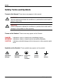
RIGOL Quick Guide DS2000 Series Digital Oscilloscope Jul. 2012 RIGOL Technologies, Inc RIGOL Guaranty and Declaration Copyright © 2012 RIGOL Technologies, Inc. All Rights Reserved. Trademark Information RIGOL is a registered trademark of RIGOL Technologies, Inc. Publication Number QGA13004-1110 Notices RIGOL products are protected by patent law in and outside of P.R.C. RIGOL reserves the right to modify or change parts of or all the specifications and pricing policies at company’s sole decision. Information in this publication replaces all previously corresponding material. RIGOL shall not be liable for losses caused by either incidental or consequential in connection with the furnishing, use or performance of this manual as well as any information contained. Any part of this document is forbidden to be copied or photocopied or rearranged without prior written approval of RIGOL. Product Certification RIGOL guarantees this product conforms to the national and industrial standards in China as well as the ISO9001:2008 standard and the ISO14001:2004 standard. Other international standard conformance certification is in progress. Contact Us If you have any problem or requirement when using our products, please contact RIGOL Technologies, Inc. or your local distributors, or visit: www.rigol.com. DS2000 Quick Guide I RIGOL Safety Requirement General Safety Summary Please review the following safety precautions carefully before putting the instrument into operation so as to avoid any personal injuries or damages to the instrument and any product connected to it. To prevent potential hazards, please use the instrument only specified by this manual. Use Proper Power Cord. Only the power cord designed for the instrument and authorized by local country could be used. Ground The Instrument. The instrument is grounded through the Protective Earth lead of the power cord. To avoid electric shock, it is essential to connect the earth terminal of power cord to the Protective Earth terminal before any inputs or outputs. Connect the Probe Correctly. Do not connect the ground lead to high voltage since it has the isobaric electric potential as ground. Observe All Terminal Ratings. To avoid fire or shock hazard, observe all ratings and markers on the instrument and check your manual for more information about ratings before connecting. Use Proper Overvoltage Protection. Make sure that no overvoltage (such as that caused by a thunderstorm) can reach the product, or else the operator might expose to danger of electrical shock. Do Not Operate Without Covers. Do not operate the instrument with covers or panels removed. Use Proper Fuse. Please use the specified fuses. II DS2000 Quick Guide RIGOL Avoid Circuit or Wire Exposure. Do not touch exposed junctions and components when the unit is powered. Do Not Operate With Suspected Failures. If you suspect damage occurs to the instrument, have it inspected by qualified service personnel before further operations. Any maintenance, adjustment or replacement especially to circuits or accessories must be performed by RIGOL authorized personnel. Keep Well Ventilation. Inadequate ventilation may cause increasing of temperature or damages to the device. So please keep well ventilated and inspect the intake and fan regularly. Do Not Operate in Wet Conditions. In order to avoid short circuiting to the interior of the device or electric shock, please do not operate in a humid environment. Do Not Operate in an Explosive Atmosphere. In order to avoid damages to the device or personal injuries, it is important to operate the device away from an explosive atmosphere. Keep Product Surfaces Clean and Dry. To avoid the influence of dust and/or moisture in air, please keep the surface of device clean and dry. Electrostatic Prevention. Operate in an electrostatic discharge protective area environment to avoid damages induced by static discharges. Always ground both the internal and external conductors of the cable to release static before connecting. Handling Safety Please handle with care during transportation to avoid damages to buttons, knob interfaces and other parts on the panels. DS2000 Quick Guide III RIGOL Safety Terms and Symbols Terms in this Manual. These terms may appear in this manual: WARNING Warning statements indicate the conditions or practices that could result in injury or loss of life. CAUTION Caution statements indicate the conditions or practices that could result in damage to this product or other property. Terms on the Product. These terms may appear on the Product: DANGER WARNING CAUTION indicates an injury or hazard may immediately happen. indicates an injury or hazard may be accessible potentially. indicates a potential damage to the instrument or other property might occur. Symbols on the Product. These symbols may appear on the product: Hazardous Voltage IV Please Refer to Manuals Protective Earth Terminal Chassis Ground Test Ground DS2000 Quick Guide RIGOL Measurement Category Measurement Category DS2000 series digital oscilloscopes can make measurements in Measurement Category I. WARNING This oscilloscope can only be used for measurements within its specified measurement categories. Measurement Category Definitions Measurement category I is for measurements performed on circuits not directly connected to MAINS. Examples are measurements on circuits not derived from MAINS, and specially protected (internal) MAINS derived circuits. In the latter case, transient stresses are variable; for that reason, the transient withstand capability of the equipment is made known to the user. Measurement category II is for measurements performed on circuits directly connected to the low voltage installation. Examples are measurements on household appliances, portable tools and similar equipment. Measurement category III is for measurements performed in the building installation. Examples are measurements on distribution boards, circuit-breakers, wiring, including cables, bus-bars, junction boxes, switches, socket-outlets in the fixed installation, and equipment for industrial use and some other equipment, for example. Stationary motors with permanent connection to the fixed installation. Measurement category IV is for measurements performed at the source of the low-voltage installation. Examples are electricity meters and measurements on primary overcurrent protection devices and ripple control units. DS2000 Quick Guide V RIGOL Ventilation Requirement This oscilloscope uses fan to force cooling. Please make sure that the air intake and exhaust areas are free from obstructions and have free air. When using the oscilloscope in a bench-top or rack setting, provide at least 10 cm clearance beside, above and behind the instrument for adequate ventilation. WARNING Inadequate ventilation may cause temperature increase which would damage the instrument. So please keep the instrument well ventilated during operation and inspect the intake and fan regularly. VI DS2000 Quick Guide RIGOL Working Environment Temperature Operating: 0℃ to +50℃ Non-operating: -20℃ to +70℃ Humidity Under +35℃: ≤90% relative humidity +35℃ to +40℃: ≤60% relative humidity WARNING To avoid short circuit inside the instrument or electric shock, please do not operate in humid environment. Altitude Operating: less than 3 km Non-operating: less than 15 km Installation (overvoltage) Category This product is powered by mains conforming to installation (overvoltage) category II. WARNING Make sure that no overvoltage (such as that caused by thunderbolt) can reach the product, or else the operator might expose to danger of electric shock. Installation (overvoltage) Category Definitions Installation (overvoltage) category I refers to signal level which is applicable to equipment measurement terminals connected to the source circuit. In these terminals, precautions are done to limit the transient voltage to the corresponding low level. Installation (overvoltage) category II refers to the local power distribution level which is applicable to equipment connected to the AC line (AC power). DS2000 Quick Guide VII RIGOL Pollution Degree Degree 2 Pollution Degree Definitions Pollution degree 1: No pollution or only dry, non-conductive pollution occurs. The pollution has no influence. For example: a clean room or air-conditioned office environment. Pollution degree 2: Normally only dry, non-conductive pollution occurs. Occasionally a temporary conductivity caused by condensation may occur. For example: general indoor environment. Pollution degree 3: Conductive pollution occurs, or dry, non-conductive pollution occurs which becomes conductive due to condensation which is expected. For example: Sheltered outdoor environment. Pollution degree 4: Pollution that generates persistent conductivity through conductive dust, rain, or snow. For example: outdoor locations. Safety Class Class 1 – Grounded Product VIII DS2000 Quick Guide RIGOL General Care and Cleaning General Care: Do not store or leave the instrument at places where the instrument will be exposed to direct sunlight for long periods of time. Cleaning: Clean the instrument regularly according to its operating conditions. To clean the exterior surface: 1. Disconnect the instrument from all power sources. 2. Clean the loose dust on the outside of the instrument with a lint- free cloth (with mild detergent or water). When cleaning the LCD, take care to avoid scarifying it. CAUTION To avoid damages to the instrument, do not expose them to corrosive liquids. WARNING To avoid injury resulting from short circuit, make sure the instrument is completely dry before reconnecting it to a power source. DS2000 Quick Guide IX RIGOL Environmental Considerations The following symbol indicates that this product complies with the applicable European Union requirements according to Directives 2002/96/EC on waste electrical and electronic equipment (WEEE). Product End-of-Life Handling The equipment may contain substances that could be harmful to the environment or human health. In order to avoid release of such substances into the environment and harm to human health, we encourage you to recycle this product in an appropriate system that will ensure that most of the materials are reused or recycled appropriately. Please contact your local authorities for disposal or recycling information. X DS2000 Quick Guide RIGOL Contents Guaranty and Declaration .........................................................................I Safety Requirement ................................................................................ II General Safety Summary ........................................................................... II Safety Terms and Symbols ....................................................................... IV Measurement Category ............................................................................. V Ventilation Requirement ........................................................................... VI Working Environment ............................................................................. VII General Care and Cleaning ....................................................................... IX Environmental Considerations .................................................................... X Quick Start ............................................................................................... 1 General Inspection ................................................................................... 1 Appearance and Dimensions ...................................................................... 2 To Prepare for Operation ........................................................................... 3 To Adjust the Supporting Legs............................................................. 3 To Connect to AC Power Supply........................................................... 4 Power-on Inspection .......................................................................... 5 To Connect the Probe ......................................................................... 6 Function Inspection............................................................................ 7 Probe Compensation .......................................................................... 9 Front Panel Overview ...............................................................................10 Rear Panel Overview ................................................................................11 Front Panel Function Overview..................................................................13 VERTICAL ........................................................................................13 HORIZONTAL ...................................................................................14 TRIGGER .........................................................................................15 CLEAR .............................................................................................16 RUN/STOP .......................................................................................16 SINGLE ............................................................................................16 AUTO...............................................................................................16 Knob ...............................................................................................17 Navigation Knob ...............................................................................17 MENU ..............................................................................................18 Record .............................................................................................19 DS2000 Quick Guide XI RIGOL Print ................................................................................................ 19 User Interface......................................................................................... 20 To Use the Security Lock .......................................................................... 24 To Use the Rack Mount Kit ....................................................................... 25 Kit Parts List..................................................................................... 25 Installation Tool ................................................................................ 26 Installation Space ............................................................................. 26 Installation Procedures ...................................................................... 27 To Use the Built-in Help System ................................................................ 30 Troubleshooting ..................................................................................... 31 XII DS2000 Quick Guide RIGOL Quick Start General Inspection 1. Inspect the shipping container for damage. Keep the damaged shipping container or cushioning material until the contents of the shipment have been checked for completeness and the instrument has passed both electrical and mechanical tests. The consigner or carrier shall be liable for the damage to instrument resulting from shipment. RIGOL would not be responsible for free maintenance/rework or replacement of the unit. 2. Inspect the instrument. In case of any damage, or defect, or failure, notify your RIGOL sales representative. 3. Check the Accessories Please check the accessories according to the packing lists. If the accessories are incomplete or damaged, please contact your RIGOL sales representative. DS2000 Quick Guide 1 RIGOL Appearance and Dimensions 2 Figure 1 Front View Unit: mm Figure 2 Side View Unit: mm DS2000 Quick Guide RIGOL To Prepare for Operation To Adjust the Supporting Legs Adjust the supporting legs properly to use them as stands to tilt the oscilloscope upwards for stable placement of the instrument as well as easier operation and observation of the instrument. Figure 3 To Adjust the Supporting Legs DS2000 Quick Guide 3 RIGOL To Connect to AC Power Supply This oscilloscope can accept 100-240 V, 45-440 Hz AC power supply. Please use the power cord supplied with the accessories to connect the oscilloscope to the power source as shown in the figure below. At this point, the oscilloscope is energized and the power key at the lower-left corner of the front panel is in breath state. Power Socket Figure 4 To Connect to AC Power Supply 4 DS2000 Quick Guide RIGOL Power-on Inspection When the oscilloscope is energized, press the power key at the lower-left corner of the front panel to turn on the oscilloscope. During the start-up process, the oscilloscope performs a series of self-test items and you can hear the sound of relay switching. After the self-test is finished, the welcome screen is displayed and you can view the Option Type, Option name, Option Edition and Left time of the option currently installed in the “Installed Options” pop-up dialog box on the screen. When the instrument is shipped, a trial version of the option is provided and the left time is about 2000 minutes. DS2000 Quick Guide 5 RIGOL To Connect the Probe RIGOL provides passive probes for the DS2000 series oscilloscopes. For detailed technical information of the probes, please refer to corresponding Probe User’s Guide. The following are the probes recommended for use with this oscilloscope. Model Description RP3300 350 MHz, passive probe, standard RP3500A 500 MHz, passive probe, optional Connect the Probe: 1. Connect the BNC terminal of the probe to a channel BNC connector of the oscilloscope at the front panel. 2. Connect the probe tip to the circuit point under test and connect the ground alligator clip of the probe to the circuit ground terminal. Figure 5 To Connect the Probe 6 DS2000 Quick Guide RIGOL Function Inspection 1. Press Storage Default to restore the oscilloscope to its default configuration. 2. Connect the earth alligator clip of the probe to the “Ground Terminal” under the probe compensation signal output terminal. 3. Use the probe to connect the input terminal of CH1 of the oscilloscope and the “Compensation Signal Output Terminal” of the probe. Compensation Signal Output Terminal Ground Terminal Figure 6 To Use the Compensation Signal 4. Press AUTO. 5. Observe the waveform on the display. In normal condition, the display should be a square waveform as shown in the figure below: Figure 7 Square Waveform 6. Use the same method to test the other channels. If the square waveforms actually shown do not match that in the figure above, please perform “Probe Compensation”. WARNING To avoid electric shock during the use of probe, please make sure that the insulated wire of the probe is in good condition and do not touch the metallic part of the probe when the probe is connected to high voltage source. DS2000 Quick Guide 7 RIGOL Tip The signal output from the probe compensation connector can only be used for probe compensation adjustment and can not be used for calibration. 8 DS2000 Quick Guide RIGOL Probe Compensation When the probes are used for the first time, you should compensate the probes to match the input channels of the oscilloscope. Non-compensated or poorly compensated probes may cause measurement inaccuracy and error. The probe compensation procedures are as follows: 1. Perform step 1, 2, 3 and 4 of “Function Inspection”. 2. Check the displayed waveforms and compare them with the following figures. Over compensated Perfectly compensated Under compensated Figure 8 Probe Compensation 3. Use a nonmetallic driver to adjust the low-frequency compensation adjustment hole on the probe until the displayed waveform is as the “Correctly compensated” in the figure above. DS2000 Quick Guide 9 RIGOL Front Panel Overview 1 3 2 11 12 13 14 15 4 16 5 6 17 18 7 19 8 9 10 20 Figure 9 Front Panel Overview No. 10 Description No. Description 1 MENU 11 Power Key 2 LCD 12 USB HOST Interface 3 Knob 13 HORIZONTAL Control Area 4 Function Menus 14 Function Menu Setting Softkeys 5 Navigation Knob 15 VERTICAL Control Area 6 CLEAR 16 Analog Channel Input Area 7 AUTO 17 Waveform Record/Playback 8 RUN/STOP 18 TRIGGER Control Area 9 SINGLE 19 EXT TRIG Input Terminal 10 Help/Print 20 Probe Compensation Signal Output Terminal/ Ground Terminal DS2000 Quick Guide RIGOL Rear Panel Overview 1 7 6 2 5 3 4 Figure 10 Rear Panel Overview 1. Handle Pull up the handle vertically for easy carrying of the instrument. When you do not need the handle, press it down. 2. LAN Connect the instrument to the network via this interface for remote control. This oscilloscope conforms to the LXI-C class instrument standards and can quickly build test system with other instruments. 3. USB DEVICE PictBridge printer or PC can be connected via this interface to print waveform data or control the instrument using PC software. DS2000 Quick Guide 11 RIGOL 4. Trigger Out The oscilloscope outputs a signal that can reflect the current capture rate of the oscilloscope at each trigger via this interface. 5. Lock Hole You can lock the instrument to a fixed location using the security lock (please buy it yourself) via the lock hole. 6. AC Power Socket AC power input terminal. The power requirement of this oscilloscope is 100-240 V, 45-440 Hz, CAT II. Use the power cord provided with the accessories to connect the instrument to AC power. Then, you can press the power key at the front panel to start the instrument. 7. Fuse If a new fuse is required, please use the specified fuse (250V, T2A). 12 DS2000 Quick Guide RIGOL Front Panel Function Overview VERTICAL CH1, CH2: analog input channels. The 2 channels are marked by different colors which are also used to mark both the corresponding waveforms on the screen and the channel input connectors. Press any key to open the corresponding channel menu and press again to turn off the channel. MATH: press this key to open the math operation menu under which add, subtract, multiply, divide, FFT, logic and advanced operations are provided. REF: press this key to enable the reference waveform function to compare the waveform actually tested with the reference waveform to decide circuit failures. POSITION: modify the vertical position of the current channel Vertical waveform. Turn clockwise to increase the position and turn counterclockwise to decrease. During the modification, the waveform would move up and down and the position message (e.g. ) at the lower-left corner of the screen would change accordingly. Press down this knob to quickly reset the vertical position to zero. VERTICAL SCALE: modify the vertical scale of the current channel. Turn clockwise to decrease the scale and turn counterclockwise to increase. During the modification, the amplitude of the waveform would enlarge or reduce and the scale information (e.g. ) at the lower side of the screen would change accordingly. Press down this knob to quickly switch the vertical scale adjustment modes between “Coarse” and “Fine”. DS2000 Quick Guide 13 RIGOL Decode1, Decode2: decoding function keys. Press the corresponding key to open the decoding function menu. DS2000 supports parallel decoding and protocol decodings. HORIZONTAL MENU: press this key to open the horizontal control menu under which to turn on or off the delayed sweep function, switch between different time base modes, switch between “Coarse” and “Fine” adjustment of scale as well as modify the horizontal reference setting. HORIZONTAL SCALE: modify the horizontal time base. Turn clockwise to reduce the time base and turn counterclockwise to increase the time base. During the modification, waveforms of all the channels will be displayed in expanded or compressed mode and the time base message (e.g. ) at the upper side of the screen would change accordingly. Press down this knob to quickly switch to delayed sweep state. HORIZONTAL POSITION: modify the trigger position. The trigger point would move left or right relative to the center of the screen when you turn the knob. During the modification, waveforms of all the channels would move left or right and the trigger position message (e.g. ) at the upper-right corner of the screen would change accordingly. Press down this knob to quickly reset the trigger position (or the delayed sweep position). 14 DS2000 Quick Guide RIGOL TRIGGER MODE: press this key to switch the trigger mode to Auto, Normal or Single and the corresponding state backlight of the current trigger mode would be illuminated. LEVEL: modify the trigger level. TRIGGER Turn clockwise to increase the level and turn counterclockwise to reduce the level. During the modification, the trigger level line would move up and down and the value in the trigger level message box (e.g. ) at the lower-left corner of the screen would change accordingly. Press down the knob to quickly reset the trigger level to zero point. MENU: press this key to open the trigger operation menu. This oscilloscope provides various trigger types. FORCE: in Normal and Single trigger modes, press this key to generate a trigger signal forcefully. DS2000 Quick Guide 15 RIGOL CLEAR Press this key to clear all the waveforms on the screen. If the oscilloscope is in “RUN” state, new waveforms will still be displayed. RUN/STOP Press this key to set the state of the oscilloscope to “RUN” or “STOP”. In “RUN” state, the key is illuminated in yellow. In “STOP” state, the key is illuminated in red. SINGLE Press this key to set the trigger mode to “Single”. In single trigger mode, press FORCE to generate a trigger signal immediately. AUTO Press this key to enable the waveform auto setting function. The oscilloscope will automatically adjust the vertical scale, horizontal time base and trigger mode according to the input signal to realize optimum waveform display. Note: auto setting requires that the frequency of the signal under test should be no lower than 50 Hz, the duty cycle be greater than 1% and the amplitude be at least 20 mVpp. If the parameters exceed these limits, “Auto failed !” would be displayed after pressing this key and the quick parameter measurement menu might not be displayed. 16 DS2000 Quick Guide RIGOL Knob Adjust waveform brightness: In non-menu-operation mode (menu is hidden), turn this knob to adjust the brightness of waveform display. The adjustable range is from 0% to 100%. Turn clockwise to increase the brightness and counterclockwise to reduce. Press down this knob to reset the brightness to 50%. You can also press Display WaveIntensity and use the knob to adjust the waveform brightness. Multifunctional Knob (the backlight goes on during operation): In menu operation, press any menu softkey and turn the knob to select the submenus under this menu and then press down the knob to select the current submenu. It can also be used to modify parameters and input filename. Navigation Knob This knob provides quick Adjust/Locate function for numerical parameters with relatively large settable range. Turn clockwise (counterclockwise) to increase (reduce) the value. The inner knob is used for fine adjustment and the outer knob for coarse adjustment. For example, this knob can be used to quickly locate the waveform frame (“Current Frame” menu) to be played back in the waveform playback function. Similar menus include trigger holdoff, pulse width setting, slope time etc. DS2000 Quick Guide 17 RIGOL MENU Measure: press this key to open the measurement setting menu. You can set the measurement setting, all measure, statistic function etc. Press MENU at the left of the screen to open the measurement menus of 22 waveform parameters. Then, press down the corresponding menu softkey to quickly realize one-key measurement and the measurement result will be displayed at the bottom of the screen. Acquire: press this key to enter the sample setting menu to set the acquisition mode, memory depth and antialiasing function of the oscilloscope. Storage: press this key to enter file store and recall interface. The storable file types include traces, waveforms, setups, picture and CSV. Internal and external storage as well as disk management are also supported. Cursor: press this key to enter cursor measurement menu. The oscilloscope provides three cursor modes: manual, track and auto. Display: press this key to enter display setting menu to set the display type, persistence time, wave intensity, grid type, grid brightness and menu display time of the waveform. Utility: press this key to enter the system function setting menu to set the system-related functions or parameters, such as I/O setting, sound and language. Besides, some advanced functions (such as pass/fail test, waveform record and print setting) are also supported. 18 DS2000 Quick Guide RIGOL Record Stop Play/Pause Record Record: press this key to start recording the waveform. The backlight is illuminated in red. Besides, when record constant on (Open) is enabled, the backlight will also be illuminated. Play/Pause: in stop or pause state, press this key to play back the waveform and press again to pause the play. The backlight is illuminated in yellow. Stop: press this key to stop the waveform being recorded or being played back. The backlight is illuminated in orange. Print Press this key to execute the print function or save the screen in the USB storage device. If a PictBridge printer is currently connected and the printer is in idle state, pressing this key will execute the print function. If no printer but a USB storage device is currently connected, pressing this key will save the screen to the USB storage device in “.bmp” format (if the current storage type is picture, the screen will be saved in the USB storage device in picture format). When printer and USB storage device are connected at the same time, the printer enjoys higher priority. DS2000 Quick Guide 19 RIGOL User Interface DS2000 provides 8.0 inches, WVGA (800*480) 160,000 color TFT LCD. What is worth mentioning is that the 14-grid ultra-wide screen enables you to view “longer” waveform. 1 2 3 12. 12 4 13 5 6 7 1414. 8 15 9 10 11 16. 16 Figure 11 User Interface 1. Auto Measurement Items Provide 12 horizontal (HORIZONTAL) and 12 vertical (VERTICAL) measurement parameters. Press the softkey at the left of the screen to activate the corresponding measurement item. Press MENU continuously to switch between the horizontal and vertical parameters. 2. Channel Label/Waveform Different channels are marked by different colors and the color of the waveform 20 DS2000 Quick Guide RIGOL complies with the color of the channel. 3. Status Available states include RUN, STOP, T’D (triggered), WAIT and AUTO. 4. Horizontal Time Base Represent the time per grid on the horizontal axis on the screen. Use HORIZONTAL SCALE to modify this parameter. The range available is from 2.000 ns to 1.000 ks. 5. Sample Rate/Memory Depth Display the current sample rate and memory depth of the oscilloscope. Use HORIZONTAL SCALE to modify this parameter. 6. Waveform Memory Provide the schematic diagram of the memory position of the waveform currently on the screen. waveform on the screen 7. Trigger Position Display the trigger position of the waveform in the waveform memory and on the screen. 8. Trigger Position Use HORIZONTAL POSITION to modify this parameter. Press down the knob to automatically set the parameter to zero. 9. Trigger Type Display the currently selected trigger type and trigger condition setting. Different labels are displayed when different trigger types are selected. For example: represents triggering on the rising edge in “Edge” trigger. 10. Trigger Source Display the trigger source currently selected (CH1, CH2, EXT, or AC Line). Different labels are displayed when different trigger sources are selected and the color of the trigger parameter area will change accordingly. For example: denotes that CH1 is selected as the trigger source. 11. Trigger Level at the right of the screen is the trigger level label and the trigger level value is displayed at the upper-right corner of the screen. When using TRIGGER LEVEL to modify the trigger level, the trigger level value will change with the up and down of . Note: in slope trigger, runt trigger and windows trigger, there are two trigger level labels ( and ). DS2000 Quick Guide 21 RIGOL 12. CH1 Vertical Scale Display the voltage value per grid of CH1 waveform vertically. Use VIRTICAL SCALE to modify this parameter. The following labels will be displayed according to the current channel setting: channel coupling (e.g. ) and bandwidth limit (e.g. ). 13. CH2 Vertical Scale Display the voltage value per grid of CH2 waveform vertically. Use VIRTICAL SCALE to modify this parameter. The following labels will be displayed according to the current channel setting: channel coupling (e.g. ) and bandwidth limit (e.g. ). 14. Message Box Display prompt messages. 15. Notification Area Display system time, sound icon and USB storage device icon. System Time: displayed in “hh:mm (hour:minute)” format. When printing or storing the waveform, the output file will contain this time message. Press Utility System System Time to set through the following format: yyyy-mm-dd hh-mm-ss (year-month-date hour-minute-second) Sound Icon: when sound is enabled, will be displayed. Press Utility Sound to enable or disable the sound. USB Storage device Icon: when a USB storage device is detected, will be displayed. 16. Operation MENU Press any softkey to activate the corresponding menu. The following symbols might be displayed in the menu: Denote that at the front panel can be used to select parameter items. The backlight of turns on when parameter selection is valid. can be used to modify parameter values. The Denote that backlight of turns on when parameter input is valid. Denote that you can use the Navigation Knob to quickly adjust/locate parameters. to adjust the parameter and then press Denote that you can use down to select the parameter. Denote that the current menu has several options. Denote that the current menu has a lower level menu. Press this key to return to the previous menu. 22 DS2000 Quick Guide RIGOL Note: the following direction keys might appear in the grid at the lower-left corner of the menu bar: Denote that you can open the next page menu. Denote that you can open the previous page menu. DS2000 Quick Guide 23 RIGOL To Use the Security Lock If needed, you can use the security lock (please buy it yourself) to lock the oscilloscope to a fixed location. The method is as follows, align the lock with the lock hole and plug it into the lock hole vertically, turn the key clockwise to lock the oscilloscope and then pull the key out. Security Lock Hole Figure 12 To Use the Security Lock Note: please do not insert other articles into the security lock hole to avoid damaging the instrument. 24 DS2000 Quick Guide RIGOL To Use the Rack Mount Kit This oscilloscope can be mounted in a standard 19-inch rack cabinet that conforms to the Electric Industrial Association (EIA) standard. If needed, please buy and install the corresponding option. Kit Parts List No. Name Qty Description 1 Front Plate 1 ---- 2 Side Plate (right) 1 ---- 3 Presser feet 2 ---- 4 Side Plate (left) 1 ---- 5 Bottom Plate 1 ---- 6 M6 Screws 4 M6*16 Phil-Slot Pan Head Screw Nail 7 M4 Screws 14 M4*8 Phil-Slot Pan Head Screw Nail 8 M6 Nuts 4 M6*5 Square Machine Female Screw Contain Lock Blade DS2000 Quick Guide 25 RIGOL Installation Tool PH2 Phillips Screwdriver (recommended). Installation Space The following requirements must be fulfilled by the machine cabinet in which the instrument is mounted. The machine cabinet must be a standard 19-inch one. At least 6U (222.2 mm) height should be provided by the machine cabinet. The depth inside the machine cabinet should not be less than 400 mm. The dimensions of the instrument after being installed are shown below (the unit is mm). 26 DS2000 Quick Guide RIGOL Installation Procedures Only authorized operators can execute the installation operation. Improper installation might result in damage of the instrument or incorrect installation of the instrument on the rack. 1. Install the side plates: fix the side plates (left and right) onto the bottom plate of the rack using four M4 screws. 2. Install the front plate: fix the front plate onto the side plates (left and right) of the rack using six M4 screws. DS2000 Quick Guide 27 RIGOL 3. Place the instrument: place the instrument by aligning it with the edges of the side plates (left and right) and front plate of the rack and fix the instrument onto the bottom plate through presser feet using four M4 screws. 4. Load into the machine cabinet: mount the rack with the instrument fixed to it into a standard 19-inch machine cabinet with four M6 screws and four M6 square nuts. 28 DS2000 Quick Guide RIGOL 5. Post-installation notice: the rack occupies a height of 5U. The holes pointed out by the arrows are installation holes. Note that they should be aligned with during installation。 DS2000 Quick Guide 29 RIGOL To Use the Built-in Help System The help system of this oscilloscope provides instructions for all the function keys (including menu keys) at the front panel. Press Help to open the help interface and press again to close the interface. The help interface mainly consists of two parts. The left is “Help Options” and you can use “Button” or “Index” mode to select. The right is “Help Display Area”. Help Options Help Display Area Figure 13 Help Information Button: Default mode. In this mode, you can press the button (except the power key , the knob and the menu page up/down key / ) or rotate the navigation knob at the front panel directly to get the corresponding help information in the “Help Display Area”. Use to select “To Index” and then press the knob to switch to Index mode. Index: In this mode, use to select the item that needs to get help (for example, “Band Width”). The item currently selected is displayed in brown. Press the knob to get the corresponding help information in the “Help Display Area”. Use to select “To Button” and then press the knob to switch to Button mode. 30 DS2000 Quick Guide RIGOL Troubleshooting The commonly encountered failures and their solutions are listed below. When you encounter those failures, please solve them following the corresponding steps. If the problem remains still, please contact RIGOL and provide your device information (acquisition method: Utility System System Info). 1. The screen is still dark (no display) after power on: (1) Check if the power is correctly connected. (2) Check whether the fuse is burned out. If the fuse needs to be changed, please use the specified fuse. (3) Restart the instrument after finishing the above inspections. (4) If it still does not work correctly, please contact RIGOL. 2. The signal is sampled but no waveform of the signal is displayed: (1) Check if the probe is correctly connected to the signal connecting wire. (2) Check if the signal connecting wire is correctly connected to the BNC (namely channel connector). (3) Check if the probe is correctly connected to the item under tested. (4) Check if there are signals generated from the item under test (you can connect the probe compensation signal to the problematic channel to determine which has problems, the channel or the item under test). (5) Resample the signal. 3. The voltage amplitude measured is greater or lower than the actual value (note that this failure usually only occurs when probe is used): Check whether the attenuation coefficient of the channel complies with the attenuation ratio of the probe. 4. There is waveform display but not stable: (1) Check the trigger signal source: check whether the Source item at the trigger panel complies with the signal channel actually used. (2) Check the trigger type: general signals should use “Edge” trigger and video signal should use “Video” trigger. Only when the proper trigger type is used, can the waveform be displayed stably. (3) Change the trigger holdoff setting. DS2000 Quick Guide 31 RIGOL 5. No display after pressing RUN/STOP: Check if the MODE at the trigger panel (TRIGGER) is on “Normal” or “Single” and if the trigger level exceeds the waveform range. If yes, set the trigger level to the middle or set the MODE to “Auto”. Note: using AUTO could automatically finish the above setting. 6. The display of waveform is ladder-like: (1) The horizontal time base might be too low. Increase the horizontal time base to increase the horizontal resolution and improve the display. (2) If Type is “Vectors”, the lines between the sample points may cause ladder-like display. Set Type to “Dots” to solve the problem. 7. Fail to connect PC or PictBridge through USB: Check the IO Setting menu in Utility to make sure whether the setting in USB Device matches the device currently connected. If needed, restart the oscilloscope. 8. The USB storage can not be recognized: (1) Check if the USB storage can work normally. (2) Make sure that the USB storage being used is flash type. This oscilloscope does not support hardware type USB storage. (3) Make sure if the capacity of the USB storage is too large. It is recommended that the capacity of the USB storage being used with this oscilloscope is no larger than 8 GBytes. (4) Restart the instrument and then insert the USB storage to check it. (5) If the USB storage still can not be used normally, please contact RIGOL. 32 DS2000 Quick Guide