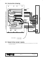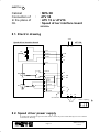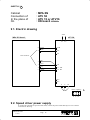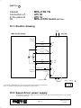
1
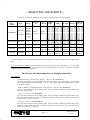
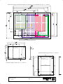
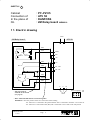
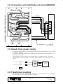
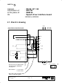
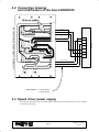
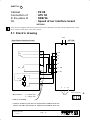
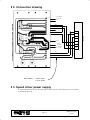
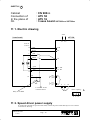
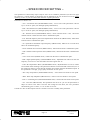
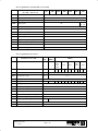
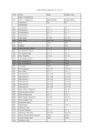
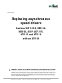
www.conairnet.com
USERGUIDE
Replacing asynchronous
speed drivers
Danfoss VLT 101.5, KEB 54,
KEB 56, AOIP ACF 215,
ATV 15 and ATV 16
with an ATV 58
WARNING - Reliance on this Manual Could Result in Severe Bodily Injury or Death!
This manual is out-of-date and is provided only for its technical information, data and capacities. Portions of this manual
detailing procedures or precautions in the operation, inspection, maintenance and repair of the product forming the subject
matter of this manual may be inadequate, inaccurate, and/or incomplete and cannot be used, followed, or relied upon.
Contact Conair at [email protected] or 1-800-654-6661 for more current information, warnings, and materials about
more recent product manuals containing warnings, information, precautions, and procedures that may be more adequate
than those contained in this out-of-date manual.
Corporate Office: 412.312.6000 l Instant Access 24/7 (Parts and Service): 800.458.1960 l Parts and Service: 814.437.6861
– SELECTING THE SHEETS –
Select the correct sheet depending on the cabinet and the speed driver to be replaced :
Speed
driver /
cabinet
PY–PZ
85
PZ
86–87–88
Add an
interface
board
40E7070x
20E65501
or
and con40E7090x sult sheet
2 (page
6)
Sheet 1
(page 4)
Sheet 2
(page 6)
40E7090x
X
Sheet 3
(page 8)
Sheet 4
(page 10)
KEB 56
40E7090x
X
X
Sheet 5
(page 12)
ATV 15
40E7080x
X
X
Sheet 6
Sheet 7
(page 14) (page 16)
ATV 16
40E6680x
X
X
DANFOSS
KEB 54
AOIP ACF215
KIT
PX 85
X
P900
P900+
CN900++ MPA XE MPA XN
MPA–II
XN–YN
ÉÉÉÉ
ÉÉÉÉ
ÉÉÉÉ
ÉÉÉÉ
ÉÉÉÉ
ÉÉÉÉ
ÉÉÉÉ
ÉÉÉÉ
ÉÉÉÉ
ÉÉÉÉ
ÉÉÉÉ
ÉÉÉÉ
ÉÉÉÉ
ÉÉÉÉ
ÉÉÉÉ
ÉÉÉÉ
ÉÉÉÉ
ÉÉÉÉ
ÉÉÉÉ
ÉÉÉÉ
ÉÉÉÉ
ÉÉÉÉ
ÉÉÉÉ
ÉÉÉÉ
ÉÉÉÉ
ÉÉÉÉÉÉÉÉ
ÉÉÉÉ
ÉÉÉÉÉÉÉÉ
ÉÉÉÉ
ÉÉÉÉ
ÉÉÉÉ
ÉÉÉÉ
ÉÉÉÉ
ÉÉÉÉ
ÉÉÉÉ
ÉÉÉÉ
ÉÉÉÉ
ÉÉÉÉ
ÉÉÉÉ
ÉÉÉÉ
ÉÉÉÉ
ÉÉÉÉ
ÉÉÉÉ
ÉÉÉÉ
ÉÉÉÉÉÉÉÉ
ÉÉÉÉ
ÉÉÉÉ
ÉÉÉÉ
ÉÉÉÉ
ÉÉÉÉ
ÉÉÉÉ
Sheet 7
Sheet 11
(page 16) (page 20)
Sheet 8
Sheet 9
(page 17) (page 18)
Sheet 8
Sheet 9
Sheet 10
(page 17) (page 18) (page 19)
X : If the speed drivers are replacements of the original speed driver. Consult the chapter for the original speed
driver.
If you are replacing an ATV 16, before replacing the speed driver, note the value of parameters : Acc, dEc, HSP,
UFr, ItH, FrS and tFr. The values will be used as a basis for setting the ATV 58. If it is not possible to read the
parameters, consult the tables on page 22.
In all cases, the motor must have a triangle connection.
Kits’ contents :
– DANFOSS 380 or 415 Volts three–phased –> ATV 58 : Ref. 40 E 707 0x
As well as the speed driver and an adaptor panel, this Kit contains fuses, fuse holders, a piece of DIN
rail, a single–phased transformer 230/400 +/– 15 V –> 230 V and a double pole double throw relay that
is not always useful.
– KEB 54, KEB 56 or DANFOSS 220 V single–phased –> ATV 58 : Ref. 40 E 709 0x
As well as the speed driver and an adaptor panel, this Kit contains a double pole double throw relay
that is not always useful.
– ATV 15 –> ATV 58 : Ref. 40 E 708 0x
As well as the speed driver and an adaptor panel, this Kit contains a double pole double throw relay
that is not always useful. The panel is installed in the place of the ATV 15 so that the ATV58 can be
installed without any extra boring.
– ATV 16 –> ATV 58 : Ref. 40 E 668 0x
As well as the speed driver and an adaptor panel, this Kit contains a double pole double throw relay
that is not always useful. The panel is installed in the place of the ATV 16 so that the ATV58 can be
installed without any extra boring.
Page 1
DD01T0213703
14.10.02
Mechanical adaptor panel KEB 54, KEB 56, AOIP ACF 215, DANFOSS VLT 101.5 => ATV 58
ÇÇÇÇÇÇÇ
ÉÉÉÉÉÉÉÉÉÉÉÉÉÉÉÉÉ
ÊÊÊÊÊÊÊ
ÂÂÂÂÂÂÂ
ÇÇÇÇÇÇÇ
ÇÇÇÇÇÇÇ
ÉÉÉÉÉÉÉÉÉÉÉÉÉÉÉÉÉ
ÊÊÊÊÊÊÊ
ÂÂÂÂÂÂÂ
ÇÇÇÇÇÇÇ
ÇÇÇÇÇÇÇ
ÉÉÉÉÉÉÉÉÉÉÉÉÉÉÉÉÉ
ÊÊÊÊÊÊÊ
ÂÂÂÂÂÂÂ
ÇÇÇÇÇÇÇ
ÇÇÇÇÇÇÇ
ÉÉÉÉÉÉÉÉÉÉÉÉÉÉÉÉÉ
ÊÊÊÊÊÊÊ
ÂÂÂÂÂÂÂ
ÇÇÇÇÇÇÇ
ÇÇÇÇÇÇÇ
ÉÉÉÉÉÉÉÉÉÉÉÉÉÉÉÉÉ
ÊÊÊÊÊÊÊ
ÂÂÂÂÂÂÂ
ÇÇÇÇÇÇÇ
ÇÇÇÇÇÇÇ
ÉÉÉÉÉÉÉÉÉÉÉÉÉÉÉÉÉ
ÊÊÊÊÊÊÊ
ÂÂÂÂÂÂÂ
ÇÇÇÇÇÇÇ
ÇÇÇÇÇÇÇ
ÉÉÉÉÉÉÉÉÉÉÉÉÉÉÉÉÉ
ÊÊÊÊÊÊÊ
ÂÂÂÂÂÂÂ
ÇÇÇÇÇÇÇ
ÇÇÇÇÇÇÇ
ÉÉÉÉÉÉÉÉÉÉÉÉÉÉÉÉÉ
ÊÊÊÊÊÊÊ
ÂÂÂÂÂÂÂ
ÇÇÇÇÇÇÇ
ÇÇÇÇÇÇÇ
ÉÉÉÉÉÉÉÉÉÉÉÉÉÉÉÉÉ
ÊÊÊÊÊÊÊ
ÂÂÂÂÂÂÂ
ÇÇÇÇÇÇÇ
ÇÇÇÇÇÇÇ
ÉÉÉÉÉÉÉÉÉÉÉÉÉÉÉÉÉ
ÊÊÊÊÊÊÊ
ÂÂÂÂÂÂÂ
ÇÇÇÇÇÇÇ
ÉÉÉÉÉÉÉÉÉÉÉÉÉÉÉÉÉ
ÊÊÊÊÊÊÊ
ÂÂÂÂÂÂÂ
ÇÇÇÇÇÇÇ
ÉÉÉÉÉÉÉÉÉÉÉÉÉÉÉÉÉ
ÊÊÊÊÊÊÊ
ÇÇÇÇÇÇÇ
ÉÉÉÉÉÉÉÉÉÉÉÉÉÉÉÉÉ
ÊÊÊÊÊÊÊ
ÇÇÇÇÇÇÇ
ÉÉÉÉÉÉÉÉÉÉÉÉÉÉÉÉÉ
ÊÊÊÊÊÊÊ
ÇÇÇÇÇÇÇ
ÉÉÉÉÉÉÉÉÉÉÉÉÉÉÉÉÉ
ÊÊÊÊÊÊÊ
ÉÉÉÉÉÉÉÉÉÉÉÉÉÉÉÉÉ
KEB 56
Transformer
ATV 58
DANFOSS
KEB 54
AOIP ACF 215
DIN rail fixing if supplied with the Kit
4 pins M4x15
mechanical adaptor panel ATV 16 => ATV 58
4 pins M4x15
mechanical adaptor panel ATV 15 => ATV 58
DD01T0213703
14.10.02
Page
2
In all cases, remove the protection cover to help the
speed driver cool down.
Page 3
DD01T0213703
14.10.02
SHEET N° 1
Cabinet
Connection of
In the place of
On
: PY–PZ 85
: ATV 58
: DANFOSS
: 2M Relay board 20E00216
1 1. Electric drawing
230V
2M Relay board
ATV 58
L1
L2
1022
1030
Tx
(===)
COM
AIV
GVX
GVY
+10
1029
+24
1028
SG+A
Li1 : FW
Li2 : RV
1022
RX
RY
(===)
1020
1026
Tx
U
V
W
motor coupling :
– This wire must be
soldered on the board
(see page 5)
motor
U V W
– Wires 1022 and 1028 must be connected together.
WARNING : Note the position of the two 1022 wires before cabling
. one 1022 wire is connected to the potentiometers and is connected to terminal +10 on ATV 58.
. one 1022 wire is connected to RX (RY) and is connected to wire 1028 on the relay board.
DD01T0213703
14.10.02
Page
4
1 2. Connection drawing
1026
1020
1030
1022
1028
2M RELAY BOARD
(seen from components side)
1029
Li2 Li1
+24
1022
+10 AIV COM
ATV 58
1 3. Modification of the 2M relay board
2M RELAY BOARD
(seen from solder side)
Wire to solder
1 4. Speed driver power supply
To replace the speed drivers powered with 220V, connect the power cables directly to L1 L2 as shown
in the electric drawing.
To replace the DANFOSS speed drivers powered with three–phased 380V or three–phased 415V , you
must install a transformer.
This transformer as well as the fuses and the fuse holders are supplied in the Kit : 40 E 707 0x
The transformer is fixed on the left of the adaptor panel supplied in the kit. The connection is as
follows:
Transformer 1 kVA
L1
2 x 6A aM 380 / 415V
220
2 x 8A Gg
ATV 58
L2
RAU
1 5. Transformer coupling
The transformer has a single–phased power supply. It has +/– 15 Volt terminals so that it can be adapted
to power voltages of 215 –> 245 V and 385 –> 415 Volts.
Page 5
DD01T0213703
14.10.02
SHEET N° 2
Cabinet
Connection of
In the place of
On
: PY–PZ 86 / 87
: ATV 58
: DANFOSS
: Speed driver interface board
20E33901 or 20E00339
2 1. Electric drawing
230V
Speed driver interface board
ATV 58
L1
L2
10x5
SX
10x6
COM
AIV
+10
10x1
+24
RX
Li1 : FW
10x0
Li2 : RV
10x3
GVX
10x4
10x2
U
motor
U V W
– Wire number : x = 1 for X axis
x = 2 for Y axis
– Wires 1011 (1021) and 1015 (1025)
must be connected together.
14.10.02
W
motor coupling :
– This wire must be soldered if the
board reference is 20E00339
(see page 7).
DD01T0213703
V
Page
6
2 2. Connection and modification of board 20E00339
Wire to solder
ASYNCHRONOUS SPEED DRIVER INTERFACE BOARD
10x5 (green)
10x6 (blue)
10x1 (yellow)
COM
10x0 (black)
+10
ATV 58
AIV
+24
Li1
Li2
10x3 (white)
10x4 (brown)
10x2 (red)
Wire number : x = 1 for X axis
x = 2 for Y axis
2 3. Speed driver power supply
To replace the speed drivers powered with 230V, connect the power cables directly to L1 L2 as shown
in the electric drawing.
To replace the DANFOSS speed drivers powered with three–phased 380V or three–phased 415V , you
must install a transformer.
This transformer as well as the fuses and the fuse holders are supplied in the Kit : 40 E 707 0x
The transformer is fixed on the left of the adaptor panel supplied in the kit. The connection is as
follows:
Transformer 1 kVA
L1
2 x 6A aM 380 / 415V
230
2 x 8A Gg
ATV 58
L2
RAU
2 4. Transformer coupling
The transformer has a single–phased power supply. It has +/– 15 Volt terminals so that it can be adapted
to power voltages of 215 –> 245 V and 385 –> 415 Volts.
Page 7
DD01T0213703
14.10.02
SHEET N° 3
Cabinet
Connection of
In the place of
On
: PZ 85
: ATV 58
: KEB 54
: 2M relay board 20E00216
3 1. Electric drawing
230V
2M relay board
ATV 58
L1
L2
1022R
1030
Tx
(===)
COM
AIV
GVX
GVY
+10
1029
+24
1028
SG+A
Li1 : FW
Li2 : RV
1022
RX
RY
(===)
1020
1026
Tx
U
– This wire must be
soldered on the board
(see page 9).
V
W
motor coupling :
motor
– Wires 1022 and 1028 must be connected together.
U V W
WARNING : Note the position of the two 1022 wires before cabling
. one 1022 wire is connected to the potentiometers and is connected to terminal +10
on ATV 58.
. one 1022 wire is connected to RX (RY) and is connected to wire 1028 on the relay
board.
DD01T0213703
14.10.02
Page
8
3 2. Connection drawing
(seen from components side)
2M RELAY BOARD
1026
1020
1030
1022
1022
1028
1029
Li2 Li1
+24
+10 AIV COM
ATV 58
3 3. Modification of 2M Relay board
2M RELAY BOARD
(seen from solder side)
Wire to solder
3 4. Speed driver power supply
To replace the speed drivers powered with 230V, connect the power cables directly to L1 L2 as shown
in the electric drawing.
Page 9
DD01T0213703
14.10.02
SHEET N° 4
Cabinet
Connection of
In the place of
On
: PZ 86 / 87 / 88
: ATV 58
: KEB 54
: Speed driver interface board
20E33901 or 20E00339
4 1. Electric drawing
230V
Speed driver interface board
ATV 58
L1
L2
10x5
SX
10x6
COM
AIV
+10
10x1
RX
Li1 : FW
10x0
10x3
GVX
+24
Li2 : RV
10x4
10x2
U
V
W
motor coupling :
– This wire must be soldered if the
board reference is 20E00339
(see page 11).
motor
U V W
– Wire number : x = 1 for X axis
x = 2 for Y axis
– Wires 1011 (1021) and 1015 (1025)
must be connected together.
DD01T0213703
14.10.02
Page 10
4 2. Connection drawing
and modification of the board 20E00339
ASYNCHRONOUS SPEED DRIVER INTERFACE BOARD
Wire to solder
10x5
10x6
10x1
COM
10x0 (black)
+10
+24
Li1
Li2
10x3 (white)
10x4 (brown)
10x2 (red)
Wire number : x = 1 for X axis
x = 2 for Y axis
4 3. Speed driver power supply
To replace the speed drivers powered with 230V, connect the power cables directly to L1 L2 as shown
in the electric drawing.
Page 11
DD01T0213703
14.10.02
ATV 58
AIV
SHEET N° 5
Cabinet
Connection of
In the place of
On
: PZ 88
: ATV 58
: KEB 56
: Speed driver interface board
20E33901
If the cabinet is equipped with an 88 asynchronous board ref. 20E00459, the latter must be replaced with a speed
driver interface board that is connected as follows :
5 1. Electric drawing
230V
Speed driver interface board
ATV 58
L1
SX
5x1
COM
5x0
AIV
L2
+10
+24
RX
Li1 : FW
5x2
5x5
Li2 : RV
5x4
GVX
5x3
U
V
W
motor coupling :
– Wire number :
motor
x = 0 for X axis
x = 1 for Y axis
U V W
– Shunt to be installed.
– Connect C12 and C13 from the CS1 output board to 24R for the X axis.
Connect C15 and C16 from the CS1 output board to 24R for the Y axis.
DD01T0213703
14.10.02
Page 12
5 2. Connection drawing
CS1 board
112 / 115
ASYNCHRONOUS SPEED DRIVER INTERFACE BOARD
0V
5x1
5x0
CS1 board
113 / 116
COM
5x2
+10
20V
+24
brakes
160 / 161
Li1
Carte CS1
111 / 114
Li2
5x5
5x4
5x3
Wire number : x = 0 for X axis
x = 1 for Y axis
5 3. Speed driver power supply
To replace the speed drivers powered with 230V, connect the power cables directly to L1 L2 as shown
in the electric drawing.
Page 13
DD01T0213703
14.10.02
ATV 58
AIV
SHEET N° 6
Cabinet
Connection of
In the place of
On
: PZ 87 / 88
: ATV 58
: ATV 15
: Speed driver interface board
20E33901
6 1. Electric drawing
230V
Speed driver interface board
ATV 58
L1
SX
5x1 (blue)
COM
5x0 (yellow)
AIV
L2
+10
+24
RX
Li1 : FW
5x2 (black)
5x4 (white)
Li2 : RV
5x5 (brown)
GVX
5x3 (red)
CS1
S11
RX
110/119
R1A
R1C
U
V
W
motor coupling :
– Wire number :
motor
x = 0 for X axis
x = 1 for Y axis
U V W
– Shunt to be installed
DD01T0213703
14.10.02
Page 14
6 2. Connection drawing
CS1 board
112 / 115
ASYNCHRONOUS SPEED DRIVER INTERFACE BOARD
0V
5x1 (blue)
5x0 (yellow)
COM
5x2 (black)
+10
20V
+24
160 / 161
brakes
Li1
Li2
5x4 (white)
5x5 (brown)
5x3 (red)
CS1 board
111 / 114
R1A
110 / 119
R1C
Wire number : x = 0 for X axis
x = 1 for Y axis
6 3. Speed driver power supply
To replace the speed drivers powered with 230V, connect the power cables directly to L1 L2 as shown
in the electric drawing.
Page 15
DD01T0213703
14.10.02
ATV 58
AIV
SHEET N° 7
Cabinet
Connection of
In the place of
On
: P 900 or P900+
: ATV 58
: ATV 15 or ATV 16
: CAM / CAF Axis board
7 1. Electric drawing
230V
CAM/CAF axis board
ATV 58
L1
0V
L2
COM
352 (362)
Set–point
C3
AIV
+10
C13 white–pink (yellow)
direction
C14
348 (347)
350 (360)
grey–brown
(grey)
346 (356)
K20
(K21)
Double pole
double throw
relay provided
with the kit.
0V
+24
Li1 : FW
Li2 : RV
24V
C16 white–blue
brake
release
pink–brown (pink)
C15
XR21
R1C
351 (361)
0V
R1B
U
V
W
motor coupling :
motor
Existing single pole single throw relay
U V W
7 2. Speed driver power supply
To replace the speed drivers powered with 230V, connect the power cables directly to L1 L2 as shown
in the electric drawing.
DD01T0213703
14.10.02
Page 16
SHEET N° 8
Cabinet
Connection of
In the place of
On
:
: MPA XE
ATV 58
: ATV 15 or ATV16
: Speed driver interface board
20E6550x
8 1. Electric drawing
230V
Speed driver interface board
ATV 58
L1
GV
L2
1 red
2 brown
COM
3 white
AIV
+10
6 grey
1 black
RX
+24
2
Li1 : FW
3 brown/green
RX
4 blue
5
SG
yellow
R1A
6
0V
7
Li2 : RV
green
R1C
U
V
W
AX red/blue
motor coupling :
motor
U V W
8 2. Speed driver power supply
To replace the speed drivers powered with 230V, connect the power cables directly to L1 L2 as shown
in the electric drawing.
Page 17
DD01T0213703
14.10.02
SHEET N° 9
Cabinet
Connection of
In the place of
On
: MPA XN
: ATV 58
: ATV 15 or ATV16
: XN board 20E6690x
9 1. Electric drawing
230V
MPA XN board
ATV 58
L1
9
8
brown
COM
white
AIV
L2
+10
J5N connector
3
5
4
6
pink
green
grey
yellow
+24
Li1 : FW
Li2 : RV
R1A
R1C
U
V
W
motor coupling :
motor
U V W
9 2. Speed driver power supply
To replace the speed drivers powered with 230V, connect the power cables directly to L1 L2 as shown
in the electric drawing.
DD01T0213703
14.10.02
Page 18
SHEET N° 10
Cabinet
Connection of
In the place of
On
: MPA–II XN YN
: ATV 58
: ATV 16
: MPA–II CPU board 20E7390x
10 1. Electric drawing
230V
MPA–II CPU board
ATV 58
L1
L2
J2 for X
J3 for Y
7
3
yellow
COM
white
AIV
5
green
4
brown
8
grey
Li1 : FW
pink
Li2 : RV
+24
9
J6
b14 for X
z14 for Y
white–red
(grey–red)
354 R1C
(364)
(365*)
355
R1A
U
V
to brake module
W
motor coupling :
motor
* To get the Y FREE function, wire 365 (Y brake release) must be connected to
R1C, i.e. without passing through the Speed driver OK contact.
U V W
10 2. Speed driver power supply
To replace the speed drivers powered with 230V, connect the power cables directly to L1 L2 as shown
in the electric drawing.
Page 19
DD01T0213703
14.10.02
SHEET N° 11
Cabinet
Connection of
In the place of
On
: CN 900++
: ATV 58
: ATV 16
: 3 axes board 20E7600x or 20E798xx
11 1. Electric drawing
230V
3 axes board
ATV 58
L1
L2
J6 for X
J7 for Y
16
white
COM
3
brown
AIV
2
pink
1
yellow
14
+24
green
Li1 : FW
grey
Li2 : RV
15
18
R1C
140
(141)
351
(361)
141
(4)
0V
R1A
U
V
to 4 brakes’ board
or Sécu94 board
W
motor coupling :
motor
Relay to be added
U V W
11 2. Speed driver power supply
To replace the speed drivers powered with 230V, connect the power cables directly to L1 L2 as shown
in the electric drawing.
DD01T0213703
14.10.02
Page 20
– SPEED DRIVER SETTING –
The speed driver is delivered by Sepro ready set with a set of “standard” parameters (see the list on page
24). However, a certain number of parameters must be adjusted for the axis to function correctly. When
replacing an ATV 16, use the values taken from the original speed driver.
Parameters to check or set :
– ACC : Acceleration time (ADJUSTMENT menu) : set to 0.2 sec if the speed driver is driven
by a 2–level set–point (low and high speed potentiometers).
– DEC : Deceleration time (ADJUSTMENT menu) : set to 0.4 sec if the speed driver is driven
by a 2–level set–point (low and high speed potentiometers).
– Ith : Thermal current (ADJUSTMENT menu) = motor nominal current + 10% . The motor
nominal current is taken from the motor’s identification plate.
– FrS : Nominal frequency that can be adjusted from 40 Hz to tFr (DRIVE menu). Value taken
from the motor’s identification plate.
– tFr : Speed driver maximum output frequency (DRIVE menu). Must be set to at least 40%
above the nominal frequency.
– NCR : Nominal current of motor (DRIVE menu) : taken from the motor’s identification plate.
– NSP : Nominal rotation speed of motor (DRIVE menu) : taken from the motor’s identification
plate.
– COS : Power factor (DRIVE menu) : taken from the motor’s identification plate.
– HSP : High speed frequency (ADJUSTMENT menu) : adjustable from LSP to tFr. Set this
frequency to 67 Hz or to the value taken from the original ATV 16.
– UFR : IR compensation =Boost (ADJUSTMENT menu) : adjustable from 0 to 150 %. It must
be increased whilst checking at all speed levels that the current measured in the motor (LCr in
the monitoring menu) is lower than the nominal current taken from the identification plate. If
this parameter is too high, you get jerky movements at slow speed.
– SLP : Slip compensation (ADJUSTMENT menu) : cancel if the axis blocks at slow speed.
– BRA : DEC ramp adaptation (DRIVE menu) : remove if the axis blocks at slow speed.
– ENT 3 : Overfluxing rate (ADVANCED DRIVE menu) : cancel if the axis blocks at slow speed.
– tUn : Auto tune (DRIVE menu). This parameter must be set to “yes” for the speed driver to
adapt its control to the motor. Once the auto tuning has been done, the “tUn” parameter
automatically goes to “done”, or “no” if there is an error.
Consult the “ATV 58 Description and Use” manual to see how to modify these parameters.
Page 21
DD01T0213703
14.10.02
ATV 16 parameters for MPA XN or YN robots
Parameters for the X and Y axes
of a PIP ... XN or YN
80
100
150
200
250
Acc
Acceleration time
0,1
dEc
Deceleration time
0,1
LSP
Low speed
HSP
High speed
UFr
Voltage / frequency law
FLG
Frequency loop gain
ItH
Motor thermal protection
SLP
Slip compensation
OFF
brA
Deceleration adaptation ramp
OFF
UFt
Type of voltage / frequency law
L
tFr
Max. frequency of speed driver
100
FrS
Nominal frequency of motor
50
UnS
Nominal voltage of motor
230
300
350
0
X : 65
Y : 38
48
50
nFL
3
ATV 16 parameters for robots ...
Parameters for a PIP ...
MPA
XE
P900
P900+
S900++
100
200
250
300
Axis
X
X&Y
X
Y
150
X
350
Y
Acc
Acceleration time
0,2
0.1
dEc
Deceleration time
0.3 –
0.5
0.1
LSP
Low speed
HSP
High speed
UFr
Voltage / frequency law
67
67
X
Y
X
Y
41 40 39 39 71 40 53 65 67 40
50
nFL
ItH
Motor thermal protection
3.0
SLP
Slip compensation
OFF
brA
Deceleration adaptation ramp
OFF
UFt
Type of voltage / frequency law
tFr
Max. frequency of speed driver
FrS
Nominal frequency of motor
50.0
UnS
Nominal voltage of motor
230
14.10.02
Y
450
0.0
FLG Frequency loop gain
DD01T0213703
X
400
500
L
67
Page 22
100
ATV 16 parameters for MPA–II XN or YN robots
Parameters for a PIP ... XN or YN
Axis
3010
X
3020
Y
X
3030
Y
3040
X
Y
X
Y
Acc
Acceleration time
0.1
dEc
Deceleration time
0.1
LSP
Slow speed
0.0
HSP
High speed
90
45
95
79
110
79
110
90
UFr
Voltage / frequency law
32
75
20
35
19
30
15
18
FLG
Frequency loop gain
ItH
Motor thermal protection
3.5
3.0
4.0
3.5
SLP
Slip compensation
OFF
brA
Deceleration ramp adaptation
OFF
UFt
Type of voltage / frequency law
L
tFr
Max. frequency of speed driver
150
FrS
Nominal frequency of motor
UnS
Nominal voltage of motor
nFL
2.5
86.0
3.0
2.5
50.0
86.0
230
ATV 58 parameters for MPA–II XN or YN robots originally equipped with an ATV 58
Parameters for a PIP ... XN or YN
Axis
3010
X
3020
Y
X
3030
Y
3040
X
Y
X
Y
Acc
Acceleration time
0.05
dEc
Deceleration time
0.05
LSP
Slow speed
0.0
HSP
High speed
77
92
95
79
95
79
95
90
UFr
Voltage / frequency law
86
100
50
85
80
80
20
40
STA
Stability
FLG
Frequency loop gain
100
ItH
Motor thermal protection
3.5
SLP
Slip compensation
brA
Deceleration ramp adaptation
yes
tFr
Max. frequency of speed driver
130
FrS
Nominal frequency of motor
UnS
Nominal voltage of motor
1
1
50 for 230 / 400 V motor coupled at 230 V (triangle)
86 for 127 / 230 V motor coupled at 127 V (triangle)
230
Page 23
DD01T0213703
14.10.02
Drive control
UNS
Nominal Voltage
230 V
230 V
FRS
Nominal Frequency
86.0 Hz
50.0 Hz
NCR
Nominal Current
3.7 A
3.5 A
NSP
Nominal Speed
2386 RPM
1400 RPM
COS
Power Factor
0.7
0.77
TUN
Auto Tune
No
No
TFR
Maximum Output Frequency
130.0 Hz
60.0 Hz
NLD
Energy Saving
No
No
BRA
Decel. Ramp Adaptation
Yes
No
FRT
Switch to Ramp 2 Frequency
0.0 Hz
0.0 Hz
RPT
Type of Ramp
LIN:Linear ramp
LIN:Linear ramp
DCF
Decel. Ramp Reduction Coefficient
4
4
TLI
Torque Limit
200%
200%
CLI
Internal current limit
5.5 A
5.5 A
ADC
Automatic DC Injection
Yes
Yes
PCC
Motor Power Coefficient
1
1
SFT
Switching Frequency type
LF :Low Freq.
LF :Low Freq.
SFR
Switching Frequency
4 kHz
4 kHz
NRD
Motor Noise Reduction
Yes
Yes
SPC
Special motor
No
No
PLS
PG pulse per revolution
1
1
PGT
Type of PG
DET:Detector
DET:Detector
Command
TCC
Terminal Strip Configuration
2W :2 wire cntrl
2W :2 wire cntrl
TCT
Type of 2 wire
LEL:2 wire
LEL:2 wire
CRL
AI2 Min. Reference
4.0 mA
4.0 mA
CRH
AI2 Max. Reference
20.0 mA
20.0 mA
STR
Stored Frequency Reference
NO :no Save
NO :no Save
PST
STOP Key Priority
Yes
Yes
ADD
Drive Address
0
0
I/O Assignments
LI1
LI1 Assignment
FW :Forward
FW :Forward
LI2
LI2 Assignment
RV :Reverse
RV :Reverse
LI3
LI3 Assignment
RST:Fault Reset
PS2:2 preset SP
LI4
LI4 Assignment
NO :Not assigned
PS4:4 preset SP
LI5
LI5 Assignment
NO :Not assigned
NO :Not assigned
LI6
LI6 Assignment
NO :Not assigned
NO :Not assigned
AI1
AI1 Assignment
FRH:Freq. Ref.
FRH:Freq. Ref.
AI2
AI2 Assignment
SAI:Summed Ref.
SAI:Summed Ref.
AI3
AI3 Assignment
NO :Not assigned
NO :Not assigned
R1
R1 Assignment
FLT:VarFault
FLT:VarFault
R2
R2 Assignment
RUN:DriveRunning
OCC:Output Cont.
LO
LO Assignment
NO :Not assigned
NO :Not assigned
Page 25
DD01T0213703
14.10.02
AO
AO Assignment
NO :Not Assigned
NO :Not Assigned
Fault managment
ATR
Automatic Restart
No
No
RST
Fault Reset Type
RSP:Part. Reset
RSP:Part. Reset
OPL
Output Phse Loss
Yes
Yes
IPL
Input Phase Loss
No
No
THT
Type of Protection
ACL:Vent. Motor
ACL:Vent. Motor
LFL
Loss of Follower
No
No
FLR
Catch on fly
No
No
STP
Controlled Stop on power loss
No
No
SDD
Ramp not Followed
No
No
Communication
PRO
Protocol
Not configured
Not configured
BDR
Transmission Speed
Not configured
Not configured
FOR
Format
Not configured
Not configured
TLP
Time out
1.0 s
1.0 s
PRC
PeerCop...
No
No
GLB
Global Tx
0
0
CDN
Command Node
0
0
REG
Number of Registers
0
0
Specific card
O01
Parameter N°1
0
0
O02
Parameter N°2
0
0
O03
Parameter N°3
0
0
O04
Parameter N°4
0
0
O05
Parameter N°5
0
0
O06
Parameter N°6
0
0
O07
Parameter N°7
0
0
O08
Parameter N°8
0
0
O09
Parameter N°9
0
0
O10
Parameter N°10
0
0
O11
Parameter N°11
0
0
O12
Parameter N°12
0
0
O13
Parameter N°13
0
0
O14
Parameter N°14
0
0
O15
Parameter N°15
0
0
O16
Parameter N°16
0
0
O17
Parameter N°17
0
0
O18
Parameter N°18
0
0
O19
Parameter N°19
0
0
O20
Parameter N°20
0
0
Drive identification
Drive catalog number
ATV58*U18M2
Drive catalog number
0.75kW 1HP
DD01T0213703
14.10.02
Page 26
Input Voltage
200/240V
50/60 Hz Switch position
Produit 50Hz
Rated continuous current
4.1 A
Rated continuous current
5.6 A
Option card
No option card
Page 27
DD01T0213703
14.10.02
Conair has made the largest investment in customer support in
the plastics industry. Our service experts are available to help
with any problem you might have installing and operating
your equipment. Your Conair sales representative also can help
analyze the nature of your problem, assuring that it did not
result from misapplication or improper use.
To contact Customer Service personnel, call:
WE’RE HERE
TO HELP
HOW TO CONTACT
CUSTOMER
SERVICE
From outside the United States, call: 814-437-6861
You can commission Conair service personnel to provide onsite service by contacting the Customer Service Department.
Standard rates include an on-site hourly rate, with a one-day
minimum plus expenses.
If you do have a problem, please complete the
following checklist before calling Conair:
❒ Make sure you have all model, serial and parts list numbers for your particular equipment. Service personnel will
need this information to assist you.
BEFORE YOU
CALL ...
❒ Make sure power is supplied to the equipment.
❒ Make sure that all connectors and wires within and
between loading control and related components have been
installed correctly.
❒ Check the troubleshooting guide of this manual
for a solution.
❒ Thoroughly examine the instruction manual(s)
for associated equipment, especially controls.
Each manual may have its own troubleshooting
guide to help you.
❒ Check that the equipment has been operated as
described in this manual.
❒ Check accompanying schematic drawings for
information on special considerations.
SERVICE INFORMATION
Additional manuals and
prints for your Conair
equipment may be
ordered through the
Customer Service or
Parts Departments for
a nominal fee.
APPENDIX A-1
EQUIPMENT
GUARANTEE
PERFORMANCE
WARRANTY
Conair guarantees the machinery and equipment on this
order, for a period as defined in the quotation from date of
shipment, against defects in material and workmanship
under the normal use and service for which it was recommended (except for parts that are typically replaced after
normal usage, such as filters, liner plates, etc.). Conair’s
guarantee is limited to replacing, at our option, the part or
parts determined by us to be defective after examination.
The customer assumes the cost of transportation of the
part or parts to and from the factory.
Conair warrants that this equipment will perform at or
above the ratings stated in specific quotations covering the
equipment or as detailed in engineering specifications,
provided the equipment is applied, installed, operated and
maintained in the recommended manner as outlined in our
quotation or specifications.
Should performance not meet warranted levels, Conair at
its discretion will exercise one of the following options:
● Inspect the equipment and perform alterations or
adjustments to satisfy performance claims. (Charges
for such inspections and corrections will be waived
unless failure to meet warranty is due to misapplication, improper installation, poor maintenance practices
or improper operation.)
● Replace the original equipment with other Conair
equipment that will meet original performance claims
at no extra cost to the customer.
● Refund the invoiced cost to the customer. Credit is subject to prior notice by the customer at which time a
Return Goods Authorization Number (RGA) will be
issued by Conair’s Service Department. Returned
equipment must be well crated and in proper operating
condition, including all parts. Returns must be prepaid.
Purchaser must notify Conair in writing of any claim and
provide a customer receipt and other evidence that a claim
is being made.
WARRANTY
LIMITATIONS
APPENDIX A-2
Except for the Equipment Guarantee and Performance
Warranty stated above, Conair disclaims all other warranties with respect to the equipment, express or
implied, arising by operation of law, course of dealing,
usage of trade or otherwise, including but not limited to
the implied warranties of merchantability and fitness for
a particular purpose.
WARRANTY INFORMATION
UGE015/0499