1
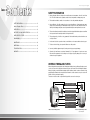
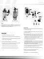
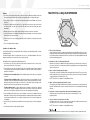
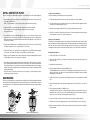
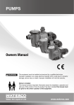
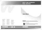
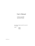
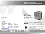
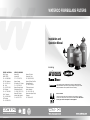
WATERCO FIBREGLASS FILTERS
Installation and
Operation Manual
Including
OFFICES - AUSTRALIA
NSW - Sydney
(HEAD OFFICE)
Tel : +61 2 9898 8686
VIC/ TAS - Melbourne
Tel : +61 3 9764 1211
WA - Perth
Tel : +61 8 9273 1900
QLD - Brisbane
Tel : +61 7 3299 9900
SA/ NT - Adelaide
Tel : +61 8 8244 6000
ACT Distributor
Tel : +61 2 6280 6476
OFFICES - OVERSEAS
Waterco USA
Augusta, USA
Tel : +1 706 793 7291
Waterco Canada
St-Hyacinthe, QC, Canada
Tel : +1 450 796 1421
Waterco (Europe) Limited
Sittingbourne, Kent. UK
Tel : +44(0) 1795 521 733
Waterco (NZ) Limited
Auckland, New Zealand
Tel : +64 9 525 7570
Waterco Limited ABN 62 002 070 733
(829006) 06/2010
Waterco (C) Limited
Guangzhou, China
Tel : +8620 3222 2180
Waterco (Far East) Sdn. Bhd.
Selangor, Malaysia
Tel : +60 3 6145 6000
PT Waterco Indonesia
Jakarta, Indonesia
Tel : +62 21 4585 1481
Waterco International Pte Ltd
Singapore
Tel : +65 6344 2378
! WARNING
This equipment must be installed and serviced by a qualified technician.
Improper installation may result in property damage, serious injury or death.
Improper installation and/or operation will void the warranty.
Notice to Installer
This manual contains important information about the installation, operation
and safe use of this product. Once the product has been installed this manual
must be given to the owner/operator of this equipment.
Waterco Fibreglass Filters I pg 01
SAFETY INFORMATION
1. Waterco fibreglass filters are designed to work with water at a temperature > than 0ºC and < than
50ºC. The filter should never be operated outside of these temperatures or damage may occur.
2. The installation should be carried out in accordance to local safety standards and bylaws.
SAFETY INFORMATION ---------------------------------------------- 01
Waterco Fibreglass Filters --------------------------------------------01
INSTALLATION -------------------------------------------------------- 02
MULTIPORT (4 & 6 Way) VALVE OPERATION ---------------------- 05
INITIAL STARTUP OF FILTER ---------------------------------------- 06
BACKWASHING ------------------------------------------------------ 06
3. Any modification of the filter requires the prior consent from Waterco. Original replacement parts
and accessories authorised by the manufacturer ensure a high level of safety. Waterco assumes no
liability for the damage and injuries caused by unauthorised replacement parts and accessories.
4. The user should make sure that the installation is carried out by qualified authorised persons and that
these persons have first carefully read the following instructions.
5. The operating safety of the filter is only guaranteed if the installation and operation instructions are
correctly followed.
MAINTENANCE ------------------------------------------------------- 08
6. In the event of defective operation or fault, contact Waterco or its nearest authorised service agent.
WINTERISING -------------------------------------------------------- 08
7. To reduce the risk of injury, do not permit children to use this product.
TROUBLESHOOTING ------------------------------------------------ 09
8. Incorrectly installed equipment may fail, causing severe injury or property damage.
WARRANTY ----------------------------------------------------------- 09
9. Chemical spills and fumes can weaken Swimming Pool / Spa equipment. Corrosion can cause
filters and other equipment to fail, resulting in severe injury or property damage. Do not store pool
chemicals near your equipment.
WATERCO FIBREGLASS FILTERS
Waterco fibreglass filters embody the latest in fibreglass winding technology. Waterco fibreglass vessels
consist of an inner shell of fiberglass reinforced polyester resin wound over with fibreglass filament.
Waterco’s digitally controlled filament winding machine faultlessly winds continuous strands of high
quality fibreglass filament under controlled tension filament to create a seamless one-piece vessel with
refined consistency and superior quality.
There are no welds or seams or special tank linings which can corrode or electrolyse.
Inflow diffuser for even distribution
of water flow across the filter bed.
Pressure gauge.
Six position Multiport valve with sight
glass and quick connect half unions.
Fibreglass wound tank, UV and
Corrosion Resistant.
Hydraulically balanced laterals to
maximise water flow and filtration.
Manual Drain*
Large filter base for stable floor
mounting.
Waterco Sidemount fibreglass filters
Waterco Top Mount fibreglass filters
* Optional manual drain
Waterco Fibreglass Filters I pg 03
MULTIPORT VALVE
INLET
VALVE
OUTLET
VALVE
OUTLET
VALVE
Waterco Sidemount fibreglass filters
Waterco Top Mount fibreglass filters
Filtration
Waterco fibreglass filters operate on the basis of “depth filtration”; dirt is driven through the filter bed
and trapped in minute spaces between the particles of filter media allowing filtered water to pass
through the filter’s laterals and exit via the filter’s Multiport valve.
Filling the Filter Media
1. Before filling the filter media into the filter vessel, do a visual check of the laterals. Look for broken or
loose laterals. Replace if necessary.
INSTALLATION
1. Position the filter as close to the Swimming Pool / Spa as possible.
2. Position the filter so that it is free from flooding, away from sumps, guttering, garden hollows, etc.
2. To eliminate stress on the laterals, fill the filter vessel half full of water to provide a cushioning effect
when the filter media is poured in.
3. (a) Top Mount Fibreglass Filters - Top Mount Fibreglass Filters are supplied with a perforated
plastic locator, which centers the stem and prevents media from entering the stem pipe. Place the
perforated plastic locator on the centre stem of the filter and carefully pour in the filter media via the
perforated holes of the plastic locator. Remove the plastic locator once completed.
3. Position the filter so that the piping connections, Multiport Valve and winter drain is convenient and
accessible for operation, servicing and winterising.
NOTE: If a template is not provided or is lost you must center the stem and cover the stem opening
to prevent non-alignment and media entering the stem pipe.
4. Ensure that the compliance label is facing the front to allow easy identification.
(b) Side Mount Fibreglass Filters (SM600) – Remove the top diffuser from the internal diffuser pipe
and place the flexible air relief tube to the side, out of the way, inside the filter vessel. Cap the internal
diffuser pipe with the filter media shield provided to prevent filter media from entering it. DO NOT
MOVE DIFFUSER PIPE as this can affect the integrity of the bulkhead seal.
NOTE: The above instructions do not apply to Sidemount Fibreglass Filters larger than SM600 filters.
Any filter media entering the diffusers will be removed during normal operation.
5. The filter should be placed on a level concrete slab, very firm ground, or equivalent. Ensure that the
ground will not subside, preventing any strain from the attached plumbing.
6. Ensure that there is no movement of the filter during operation of the Multiport Valve.
7. Allow sufficient clearance around the filter to permit visual inspection of the entire system.
4. Wash all the filter media and debris away from the threads and sealing surfaces of the filter vessel.
5. Lubricate the o-ring or gasket (bolt down type) MPV and thread to the filter.
Lubricant should be silicon based and not petrochemical based.
6. Thread the Multiport Valve or Top Cap onto the filter tank and hand tighten.
Waterco Fibreglass Filters I pg 05
Plumbing
MULTIPORT (4 & 6 Way) VALVE OPERATION
1. Check that the incoming water pressure is within the filter’s recommended working pressure and
ensure that a pressure limiting valve is installed if using mains water or a high pressure pump.
2. Ensure that a foot valve / non return valve is installed if the pump is installed 500mm / 20” above the
water level.
3. If the filter is installed below the water level or connected to mains water, isolation valves should
be installed at the inlet and outlet of the filter. This will prevent water flow during any routine
maintenance.
4. Minimise the length of pipe and the number of fittings to minimise restrictions to water flow.
5. Connect all plumbing to the Multiport Valve taking care that all plumbing connections are glued and
tightened securely to prevent leaking.
6. Ensure solvents are not excessively applied to fittings as this could run into o’rings and create sealing
problems.
7. Do not over tighten fittings or adapters.
Installation of the Multiport Valve
Top Mount Fibreglass Filters are supplied with either a Top Mount screw down Multiport Valve or clamp
down Multiport Valve.
Side Mount Fibreglass Filters are supplied with the option of a Side Mount Multiport Valve with a
plumbing kit designed to be connected to the side ports of the filter.
Each Multiport Valve is supplied three threaded barrel unions.
1. Check that the top of the filter is free from any filter media or debris and if there is a valve o’ring,
please check that the valve o’ring is in place.
2. Check the label of each valve port and position the valve accordingly. Pump port must be plumbed
to the pump discharge, waste port must be plumbed to the waste line and the return port must be
plumbed to the return line
3. Top Mount Screw Down Multiport Valve - Rotate the Multiport Valve into the filter vessel’s threaded
connection.
Top Mount Clamp Down Multiport Valve – Align the valve with the top of the tank flange. Place the
clamp half over the valve flange and the tank flange. Insert the clamp screws and nuts in the clamp,
making sure that the nuts are located in the retainer slots on the clamps. Tighten the clamp screws
firmly and check that the valve and clamp are correctly assembled.
Side Mount Multiport Valve – Align the Multiport Valve’s plumbing kit with the filter’s threaded
connection ports. Screw the plumbing kit’s barrel unions onto the filter connection ports and hand
tighten. Do not over tighten the barrel unions as this can lead to damage and void warranty.
4. Screw the Multiport Valve barrel unions onto the threaded connection ports of Multiport Valve and
hand tighten. The barrel union should be firmly threaded into the Multiport Valve and there should be
no play between the thread. Do not over tighten the barrel unions as this can lead to damage and
void warranty.
5. Glue the PVC pipe to the barrel unions and Allow 24 hours for glue (solvent) to set before starting the
filter.
1. Filter - Position for filtration.
Incoming water from the piping system is automatically directed by the Multiport Valve to the top of
the filter bed. As the water is pumped through the filter bed, dirt and debris are trapped by the filter
bed. The filtered water is returned from the bottom of the filter vessel, through the Multiport Valve and
back through the piping system.
2. Backwash - Position for cleaning the filter media.
Water flow is reversed by the Multiport Valve through the filter bed so that water flow is directed to
the bottom of the filter vessel and up through the filter bed, flushing the previously trapped dirt and
debris out the waste line.
3. Rinse - Position for flushing the filter system.
The water flow is directed by the Multiport Valve through the filter bed and out. This process settles
the filter media bed into place and ensures any dirt or debris is rinsed out of the filter, preventing dirt
or debris returning to the Swimming Pool / Spa.
NOTE: This position is not available on 4-Way Multiport Valves.
4. Waste - Position for bypassing the filter bed to waste.
The water flow is directed by the Multiport Valve straight to the backwash outlet, bypassing the entire
filter bed. This Multiport Valve position is used lower the water level or for vacuuming water with high
dirt loads.
5. Re-circulate - Position for bypassing the filter bed to the Swimming Pool / Spa.
The Mulitport valve recirculates water flow directly back to the Swimming Pool / Spa,
bypassing the filter.
6. Closed – Position for closing all flow to the filter.
The Multiport Valve can be closed to enable servicing of pump without draining the water from the
filter. This position is not to be used with the pump operating.
NOTE: This position is not available on 4-Way Multiport Valves.
6. Test the filter and check for leaks around the threads.
!
Operation of the Multiport Valve or mode selection is to be always done with the pump switched off.
Waterco Fibreglass Filters I pg 07
INITIAL STARTUP OF FILTER
Conditions for Backwashing :-
Be sure correct amount of filter media is in the filter vessel and that all connections are hand tightened.
Time for backwashing is determined by the following conditions:
1. Depress Multiport Valve handle and rotate to the BACKWASH position and open the air release valve
on the filter or Multiport Valve.
1. The flow rate through the filter bed decreases until it is insufficient to meet the demand.
2. The removal efficiency of the filter bed decreases to the point where filter water quality deteriorates
or results in dirt or debris returning to the pool.
NOTE: To prevent damage to control valve seal, always depress handle before turning.
2. Switch on the Pump / Open the Inlet Valve allowing the filter vessel to fill with water.
3. When the pressure gauge reading is 50 kPa (7.2 psi) higher than the start up pressure.
NOTE: If a pump is installed, switch the pump on and off, instead of closing and
opening the Inlet Valve.
3. One a steady flow of water is running through the waste line, close the air release valve and let the
pump run until the waste water is clear. The initial backwashing of the filter is recommended to
remove any impurities or fine particles from the filter media until the sight glass is clear. This process
may take up to 3 minutes.
4. Turn the pump off, Multiport Valve to the RINSE position. Switch on the Pump / Open the Inlet Valve
until water in sight glass is clear — approximately 10 to 15 seconds .
5. Switch off the Pump / Close the Inlet Valve, set the Multiport Valve to the FILTER position and Switch
on the Pump / Open the Inlet. The filter is now operating in its normal filter mode.
6. Adjust pool suction and return valves to achieve desired flow. Check the plumbing and filter for water
leaks and tighten connections, bolts, and nuts, as required.
7. Record the pressure gauge reading (start up pressure) during initial operation. After a period of time,
the accumulated dirt and debris in the filter causes a resistance to flow, and the flow diminishes.
The pressure will start to rise and the flow of water will start diminishing. When the pressure gauge
reading is 50 kPa (7.2 psi) higher than the initial “Start up” pressure, it is time to backwash (clean) the
filter (see Backwashing).
NOTE: If the filter is connected to mains water, it is not necessary to record the “Start up” pressure,
as mains pressure tends to fluctuate.
BACKWASHING
The function of backwashing is to separate the deposited particles from the filter media grains and flush
them from the filter bed. Backwashing is achieved by reversing the flow of water through the filter bed
at a fairly high flow rate. This high flow rate expands the filter bed and the water flow carries the debris
out to waste.
MULTIPORT VALVE
DIRT
FLUSHED OUT
TO DRAIN
TO WASTE
INLET
VALVE
DIRT
FLUSHED OUT
4. If the filter is connected to mains water, pressure rise is not an accurate indicator as mains pressure
tends to fluctuate. It is best to rely on the actual flow rate.
Importance of Backwashing
The importance of backwashing cannot be overstated. Dense filter media can become “packed” without
proper and frequent enough backwashing. Debris will remain trapped and create channeling within the
filter bed. This will result in the filter bed exhausting early. Moreover, if debris is not flushed from the
media grains, the filter bed will become dirtier and dirtier as time goes on until the filter operation fails.
Backwashing Instrustions :1. Switch off the Pump / Close the Inlet Valve.
2. Release the filter’s pressure by loosening Pressure Release Valve until the Pressure Gauge needle
drops to zero <0>.
3. Retighten Pressure Release Valve.
4. Depress and turn Handle 180° to the BACKWASH position.
In the BACKWASH position, the water flow is automatically reversed through the filter so that it is
directed to the bottom of the filter vessel, up through the filter bed, flushing the previously trapped
dirt and debris out the waste line.
5. Switch on the Pump / Open the Inlet Valve. Backwash water will flow out through filter bed drain
pipe.
6. When the backwash water in the sight glass appears clear, Switch off the Pump / Close the Inlet
Valve.
7. Depress and turn the handle to the RINSE position.
In the RINSE position water flow is directed through the filter bed as normal filter mode but out
through the waste outlet. This process settles the filter media bed into place and ensures any dirt or
debris is rinsed out of the filter, preventing possible return to the pool.
8. Switch on the Pump / Open the Inlet Valve. Rinse water will flow out through the drain pipe.
SAND
9. When the rinse water in the sight glass appears clear. Switch off the Pump / Close the Inlet Valve.
SAND
10.Depress and turn the handle to the Filter position and Switch on the Pump / Open the Inlet Valve for
normal operation.
Waterco Sidemount Fibreglass Filters
Waterco Top Mount Fibreglass Filters
Waterco Fibreglass Filters I pg 09
TROUBLESHOOTING GUIDE
MAINTENANCE
The filter media will only require replacement once it has reached the limits of its designated life.
Refer to the product information of the particular filter media used.
To ensure the maximum life of the selected filter media, please follow the procedures below:
Above normal or
excessive force
to operate the
Multiport Valve
1. Backwash the filter regularly according to the instructions set under “Backwashing”.
2. Refer to the specifications of the filter media used and implement regeneration procedures
accordingly.
Note: A filter sock is recommended during pool vacuuming, to prevent dirt and
debris lodging between the spider gasket and MPV body.
Water is not clear
1. Insufficient filtration time.
2. Heavy bathing or dirt load. Pool must be floculated and vacuumed
directly to waste.
3. Filter is dirty, requiring a thorough backwash.
4. Air leaking on suction (influent line).
5. Pump impeller vanes blocked.
6. In sufficient water supply (water level low, blockage).
7. Pump not primed.
8. In correct water chemistry.
9. Excessive flow of water for filter size. Foreign matter or debris forced
through filter bed and through the under drain.
10. Other restrictions including (pool suction cleaners) resistance from other
inline equipment such as strainers. Operating the filter on recirculate will
determine if the restriction is in the filter.
11. Clogged or channeled filter media. Perform thorough backwash or
regeneration.
Filter media
flushed out to
waste during
backwash
1. Excessive quantity of media in the filter.
2. Excessive water flow.
3. Incorrect sized or grade of filter media.
Filter Media
returning to
Swimming
Pool/ Spa
1.
2.
3.
4.
5.
Filter is on recirculate.
Verify it is the filter media and not from another source.
Damage to the under-drain laterals.
Damaged or incorrect connections to the Multiport Valve.
Incorrect sized or grade of filter media.
Short filtration
cycles
1.
2.
3.
4.
5.
Presence of algae or a scale build up.
Check water chemistry.
Excessive water flow, check pump size / mains water flow.
Filter blocked through calcium etc. clean filter media.
Ineffective backwash, perform thorough backwash.
High pressure on
start-up.
1. Small eyeball fitting in Pool / Spa.
2. Partially closed valve on return line.
3. Pump size is too large for the filter.
3. Maintain a correct chemical balance of your pool / spa water. The chemical balance of water is a
relationship between its pH, total alkalinity, calcium hardness and water temperature. The water must
be maintained at all times to the following:
PH LEVEL
: BETWEEN 7.2 & 7.8.
TOTAL ALKALINITY
: BETWEEN 80 & 150ppm.
CALCIUM HARDNESS
: BETWEEN 150 & 300ppm.
And within these tolerances be balanced to the Langelier Saturation Index within a range of -0.2 to
+0.2.
NOTE: Testing kits are available to test the water yourself or alternately bring a sample of the water
to a professional pool and spa shop.
4. Mains water and rural water supplies need to be monitored. Saturation (life) in mains water or bore
(rural) will vary depending on water quality.
5. To prevent damage to the pump and filter and for proper operation of the system, clean pump
strainer and skimmer baskets regularly.
6. Replace the pressure gauge if faulty readings are observed.
WINTERISING
Proper winterising procedures should always be taken in order to protect your filter in cold climates
[temperatures below freezing point]
1. Switch off the Pump / Close the Inlet Valve,
2. Open the air release valve and move the MPV handle to the winterise position [between Filter and
Waste] This will allow air to through to all ports.
3. Remove any drain plugs from the filter.
4. Drain water from the pipework.
Scoring or jamming with foreign matter or debris. If this condition persists after
rinsing, disassemble the valve to clear dirt and debris. Continued operation of the
valve may result in a non-sealing condition (damage to spider gasket). This will lead
to water loss to the backwash line or to inefficient filtration.
WARRANTY
Waterco fibreglass filters are covered by a 10-year tank warranty and 1-year warranty on all other
components. Commercial installations are covered by a 5-year (1 year full + 4 years pro rata) tank
warranty and 1-year warranty on all other components.
Please refer to Waterco’s warranty terms and conditions.