1
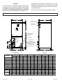
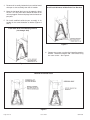
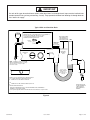
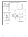
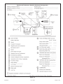
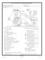
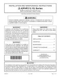
0659373-80 Version B
INSTALLATION INSTRUCTIONS
BCE3M & BCS3M SERIES AIR HANDLER
These instructions must be read and understood completely before attempting installation.
This is a safety alert symbol and should never be ignored. When you see this symbol on labels or in
manuals, be alert to the potential for personal injury or death.
WARNING
TABLE OF CONTENTS
Shipping and Packing List ........................................................ 1
Unit Dimensions ....................................................................... 2
Requirements ........................................................................... 3
Installation Clearances ............................................................. 3
Installation ................................................................................. 4
Condensate Drain ..................................................................... 7
Duct Systems and Filters ......................................................... 8
Connecting Refrigerant Lines ................................................... 9
Sealing the Unit ........................................................................ 9
Electrical Connections ............................................................ 10
Airflow - Cooling Blower Speed .............................................. 12
Check - Out Procedures ......................................................... 13
Operation ................................................................................ 13
Maintenance ........................................................................... 14
Cabinet Insulation ................................................................... 14
Warranty ................................................................................. 17
Improper installation, adjustment, alteration, service or
maintenance can cause property damage, personal injury
or loss of life. Installation and service must be performed
by a licensed professional installer (or equivalent), service
agency or the gas supplier.
CAUTION
The Clean Air Act of 1990 bans the intentional venting
of refrigerant (CFCs, HCFCs and HFCs) as of July 1,
1992. Approved methods of recovery, recycling or
reclaiming must be followed. Fines and/or incarceration
may be levied for noncompliance.
Shipping and Packing List
WARNING
Package 1 of 1 contains the following:
1 - Assembled air handler unit for upflow or horizontal air
discharge application (includes upflow and horizontal
drain pans and pre-installed air filter).
Product contains fiberglass wool.
Disturbing the insulation in this product during
installation, maintenance, or repair will expose you to
fiberglass wool. Breathing this may cause lung cancer.
(Fiberglass wool is known to the State of California to
cause cancer.)
Fiberglass wool may also cause respiratory, skin, and
eye irritation.
To reduce exposure to this substance or for further
information, consult material safety data sheets
available from address shown below, or contact your
supervisor.
Check equipment for shipping damage. If found,
immediately report damage to the last carrier. Check the
unit rating plate to confirm that delivered unit matches
order.
Manufactured By
Advanced Distributor Products
A Lennox International, Inc. Company
1995 Air Industrial Park Road
Grenada, MS 38901
NOTE: These instructions are intended as a general guide and
do not supersede national, state or local codes in any way.
(P) 507120-01
These instructions must be left with the property owner.
507120-01
*P507120-01*
Issue 1234
Page 1 of 18
GENERAL
ton, 96W38 for the 2 and 2.5 ton, 97W95 for the 3 ton, and
97W96 for the 3.5 through 5 ton). All units may be installed
with optional ECB25 field-installed electric heat and a
matched outdoor unit.
These air handlers are designed for indoor installation only.
As shipped, the unit is ready for installation in either upflow
or horizontal left-hand or right-hand air discharge
applications. Downflow applications can be accomplished
by purchasing the available downflow kit (96W37 for 1.5
All units come with a orifice metering device installed.
Unit Dimensions - Inches (mm)
B
C
3/4 (19)
LINE VOLTAGE
Right, Left and Top
LOW VOLTAGE
Right Side Only
AIR FLOW
A
CONDENSATE DRAIN
PIPING PLATE (4)
(2-1/4 x 3-3/4)
FILTER ACCESS
SUCTION
LINE
F
OPTIONAL DUCT
ADAPTOR KIT
(Kit allows direct connection of the
ductwork to the return air opening
of the air handler, not required if
an external filter is used
or if unit is installed on a
platform in upflow applications.)
LIQUID
LINE
J
E
3/4
(19)
D
H
G
(Opening)
2-1/2
(64)
1-3/4
(44)
2-1/2
(64)
inches
mm
inches
-036
-030
-024
-018
2-1/2
(64)
SIDE VIEW
FRONT VIEW
Dimension
(Opening)
mm
inches
mm
-042
inches
mm
inches
-048 / -060
mm
inches
mm
1334
A
38
965
40-1/2
1029
43
1092
48
1219
48
1219
52-1/2
B
15
381
18-1/2
470
18-1/2
470
21-7/8
556
21-7/8
556
21-7/8
556
C
22
559
22
559
22
559
22
559
26
660
26
660
D
6
152
6
152
6
152
12-1/4
311
6-1/4
159
6-3/8
162
E
11
279
14
357
16
406
18-7/8
479
17-7/8
454
15-1/4
387
F
3-5/8
92
5-1/2
140
5-1/2
140
5-3/4
146
3-1/4
83
3-1/4
83
G
10
254
13-1/2
343
13-1/2
343
16-7/8
429
16-7/8
429
16-7/8
429
H
17-3/4
451
17-3/4
451
17-3/4
451
17-3/4
451
21-3/4
552
21-3/4
552
3-5/8
92
5-1/2
140
5-1/2
140
5-3/4
146
4-5/8
117
6-3/8
162
17
432
17
432
17
432
17
432
21
533
21
533
J
Supply Air
Opening
Depth
Width
13
330
16-1/2
419
16-1/2
419
19-7/8
505
19-7/8
505
19-7/8
505
Return Air
Opening
Depth
20-3/4
527
20-3/4
527
20-3/4
527
20-3/4
527
24-3/4
629
24-3/4
629
Width
12-1/2
318
16
406
16
406
19-3/8
492
19-3/8
492
19-3/8
492
Page 2 of 18
Issue 1234
507120-01
Install the conditioned air plenum, ducts and air filters (not
provided) in accordance with NFPA 90B Standard for the
Installation of Warm Air Heating and Air-Conditioning
Systems (latest edition).
Requirements
WARNING
Excessive Weight Hazard - Use two or more people
when moving and installing the unit. Failure to do so
can result in back or other type of injury.
The air handler is shipped from the factory completely
assembled. The unit is provided with flanges for the
connection of the duct system.
Do not remove the cabinet knockouts until it has been
determined which knockouts will need to be removed for
the installation.
IMPORTANT
These units are designed to match, and must be used
with, outdoor units as rated. The indoor sections are
manufactured with a orifice metering device installed to
provide optimum refrigerant control and system
performance with a variety of different capacities of
outdoor units.
Select the final air discharge position which best suits the
site conditions. Consider required clearances, space,
routing requirements for refrigerant line, condensate
disposal, filters, duct system, wiring, and accessibility for
service. Refer to the air handler rating plate on the air
handler for specific information.
CAUTION
WARNING
Physical contact with metal edges and corners while
applying excessive force or rapid motion can result in
personal injury. Be aware of, and use caution when
working near these areas during installation or while
servicing this equipment.
These instructions are intended as a general guide and
do not supersede local or national codes in any way.
Consult authorities having jurisdiction before installation.
Compliance with all local, state, or national codes pertaining
to this type of equipment should be determined prior to
installation. Read this instruction manual, as well as the
instructions supplied in separate equipment, before starting
the installation.
In addition to conforming to manufacturer’s installation
instructions and local municipal building codes, installation
of Allied air handler units (with or without optional electric
heat), MUST conform with National Fire Protection
Association (NFPA) standards: “Standard for Installation
of Air Conditioning and Ventilation Systems” (NFPA No.
90A) and “Standard for Installation of Residence Type
Warm Air Heating and Air Conditioning Systems” (NFPA
No. 90B).
All models are designed for indoor installation only. The
installation of the air handler, field wiring, duct system, etc.
must conform to the requirements of the National Electrical
Code, ANSI/NFPA No. 70 (latest edition) in the United
States, and any state laws, and local ordinances (including
plumbing or wastewater codes). Local authorities having
jurisdiction should be consulted before installation is made.
Such applicable regulations or requirements take
precedence over the general instructions in this manual.
Danger of explosion. Keep flammable
materials and vapors, such as gasoline, away
from air handler. Place air handler so that
heating elements are at least 18 inches (46
cm) above the floor for a garage installation.
Failure to follow these instructions can result
in death, explosion, or fire.
NOTES:
During cooling operation, excessive sweating may occur
if the air handler is installed in a very humid space.
If installed in an unconditioned space, sealant should be
applied around the electrical wires, refrigerant tubing, and
condensate lines where they enter the cabinet.
Electrical wires should be sealed on the inside where they
exit the conduit opening. Sealant is required to prevent
air leakage into, and condensate from forming inside of,
the air handler, the control box, and on the electrical
controls.
This unit is approved for installation clearance to
combustible material as stated on the unit rating plate.
Accessibility and service clearances must take precedence
over combustible material clearances.
The air handler must be installed so that free access is
allowed to the coil/filter compartment and blower/control
compartment.
Horizontal applications of the air handler must be installed
sloped (approximately 5/8 inch) toward the drain pan
openings to ensure proper condensate drainage.
507120-01
Issue 1234
Page 3 of 18
Refrigerant Metering Device
Installation Clearances
NON-DUCTED RETURN CLOSET INSTALLATION
The air handler can be installed in a closet with a false
bottom to form a return air plenum. It may also be installed
with a return air plenum under the air handler.
Louvers or return air grilles are field supplied. Local codes
may limit application of systems without a ducted return to
single story buildings.
When these unit are installed in a closet with a louvered
return opening, the minimum open area for the louvers will
be:
•
•
•
These units are equipped with a orifice metering device.
Upflow Application
1. The air handler must be supported on the bottom only
and set on solid floor or field supplied support frame.
Securely attach the air handler to the floor or support
frame.
2. If installing a unit in an upflow application, remove the
horizontal drain pan.
IMPORTANT: The horizontal drain pan is not required
in upflow air discharge installations; its removal
provides the best efficiency and air flow.
320 square inches for -018 and -024 models;
360 square inches for -030 and -036 models;
450 square inches for -042 thru -060 models.
If the free area is not known, assume a 25% free area for
wood or a 75% free area for metal louvers or grilles. Using
the louver dimensions and the 25% or 75% assumption,
determine if the open area meets the minimum open area
listed above.
3. Place the unit in the desired location and level it. Connect
return and supply air plenums as required using sheet
metal screws.
4. Install units that have no return air plenum on a stand
that is at least 14" from the floor. This will allow proper
air return.
If a return air plenum is used, the return air grille should be
immediately in front of the opening in the plenum to allow
for the free flow of return air. When not installed in front of
the opening, there must be adequate clearance around
the air handler to allow for the free flow of return air.
Upflow Configuration
INSTALLATION
General Information
WARNING
Improper installation, adjustment, alteration, service or
maintenance can cause property damage, personal
injury or loss of life. Installation and service must be
performed by a qualified installer or service agency.
Figure 1
These units are factory assembled and configured for installation in upflow or horizontal left hand air discharge applications.
Each unit consists of a blower assembly, refrigerant coil,
and controls, in an insulated galvanized steel factory
finished enclosure. Knockouts are provided for electrical
wiring entrance.
For ease in installation, it is best to make any necessary
coil configuration changes before setting air handler in place.
For all performance testing, units must be tested in the
upflow orientation with the horizontal drain pan removed.
Page 4 of 18
Issue 1234
Horizontal Applications
IMPORTANT
When removing the coil, there is possible danger of
equipment damage and personal injury. Be careful
when removing the coil assembly from a unit installed
in right- or left-hand applications. The coil may tip into
the drain pan once it is clear of the cabinet. Support
the coil when removing it.
507120-01
Right-Hand Air Discharge
For horizontal right-hand air discharge, the following field
modifications are require.
Suspending Horizontal Unit
1. Remove and set aside blower and coil access covers.
2. Remove brachet(s) securing pan(s) to unit as illustrated
in Figures 4 and 5.
Remove Main Drain Pan Mounting Bracket
(-018 through -036)
Figure 2
NOTE: When the unit is installed in horizontal applications,
a secondary drain pan is recommended. Refer to local
codes.
NOTE: This unit may be installed in left-hand or righthand air discharge horizontal applications. Adequate
support must be provided to ensure cabinet integrity.
Ensure that there is adequate room to remove service and
access panels if installing in the horizontal position.
Left-Hand Discharge
1. Determine knockouts required for drain line
connections.
Figure 4
2. With access door removed, knock out drain line
opening for installing drain lines.
3. Set unit so that it is sloped toward the drain pan end of
the unit (see Figure 10).
Remove both Horizontal & Main Drain Pan Brackets
4. The horizontal configuration is shown in Figure 3.
Left-Hand Discharge Configuration
Figure 3
5. If the unit is suspended, the entire length of the cabinet
must be supported. If you use a chain or strap, use a
piece of angle iron or sheet metal attached to the unit
(either above or below) to suppor the length of the
cabinet. Use securing screws no longer than 1/2 inch
to avoid damaging the coil or filter. See Figure 2. Use
sheet metal screws to connect the return and supply
air plenums as required
507120-01
Issue 1234
Figure 5
Page 5 of 18
3. Remove coil assembly, bottom drain pan and horizontal
drain pan as one assembly from the air handler.
Install both Horizontal & Main Drain Pan Brackets
4. Move the horizontal drain pan to the opposite side of
the coil. Be sure drain holes toward the back of the
unit are plugged. Remove the plugs from the front drain
pan ports.
5. Re-install modified coil/drain pan assembly in air
handler in the same orientation as before (Figures 6
and 7).
Install Main Drain Pan Mounting Bracket
(-18 through -036)
Figure 7
6. Remove two screws securing the blow-off prevention
bracket. Rotate the brackets 180° and reinstall using
the same screws. See Figure 8.
Figure 6
Blow-Off Prevention Plate
Figure 8
Page 6 of 18
Issue 1234
507120-01
IMPORTANT
On units of this type, where the blower “draws” rather than “blows” air through the coil, traps must be installed in the
condensate drain lines (primary and auxiliary, if used). Traps prevent the blower from drawing air through the drain
lines into the air supply.
Typical Main and Overflow Drain
overflow DRAIN LINE
ABOVE
FINISHED
SPACE?
ALWAYS RUN AN overflow DRAIN LINE. IF NOT POSSIBLE TO
ROUTE overflow DRAIN LINE, INSTALL low voltage
overflow SWITCH kit. WIRE kit TO SHUT DOWN
COMPRESSOR PER INSTRUCTIONS.
ALLIED #
X3169
VENT MUST EXTEND
ABOVE HEIGHT OF
COIL DRAIN PAN BY
TWO INCHES (51MM)
VENT
CLEAN OUT
PRESS IN
(DO NOT GLUE)
NO
1” x 3/4” x 3/4”
REDUCING
TEE WITH
PLUG
air handler DRAIN PAN
OVERFLOW
drain
YES
NOTE — WHEN A air handler IS LOCATED
ABOVE a FINISHED SPACE the secondary
drain pan must have a larger footprint
than the air handler.
Lennox1 p-trap
49p66, J-TRAP #
91P90 or any
PVC SCH 40 P- or
J-Trap 3/4”
WHEN A COIL IS LOCATED ABOVE a FINISHED SPACE, A
3/4” (19.1MM) SECONDARY DRAIN LINE MUST BE:
CONNECTED TO SECONDARY DRAIN PAN
OR
CONNECTED TO THE OVERFLOW DRAIN OUTLET OF
THE AIR HANDLER DRAIN PAN.
TRAPS MUST BE DEEP ENOUGH TO OFFSET MAXIMUM STATIC DIFFERENCES —
GENERALLY, TWO INCHES (51MM).
DRAIN LINE SHOULD
SLOPE A MINIMUM OF
ONE INCH PER 10
FEET (25MM PER 3
METERS)
1 ALLIED p-tRAP 49p66 REQUIRES A LARGER INSTALLATION SPACE than the j-tRAP 91P90.
2 pipe niPPle provided in bag assembly - Sch 80, 3/4” I. D. x 5” - 34K7401 (1): Cut the pipe in half and use it to route the main drain.
Figure 9
507120-01
Issue 1234
Page 7 of 18
4. After removal of drain pan plugs, check the drain port
to see if holes have been drilled. If not drilled, use a
19/32" bit to drill out the primary drain hole; use a 3/8"
drill bit for the secondary drain hole. Remove all drill
shavings.
IMPORTANT
A field-fabricated secondary drain pan, with a drain pipe
to the outside of the building, is required in all
installations over a finished living space or in any area
that may be damaged by overflow from the main drain
pan. In some localities, local codes may require a
secondary drain pan for any horizontal installation.
5. Make sure drain ports and drain pan are free of all
debris.
6. Plug and check any unused drain pan openings for
tightness. Torque plugs to 30 in. lb. to prevent water
leaks or seepage from the drain pan.
The air handler is provided with 3/4” NPT condensate drain
connections.
Sloping the Drain
Make sure the unit is sloped (similar to the slope shown in
Figure 10) so that the drain pan will empty completely
without water standing in the pan.
Sloping the Drain
7. Install a 2" trap in the primary drain lines as close to
the unit as practical (see figure 9). Make sure the top
of the trap is below the connection to the drain pan to
allow complete drainage of the pan.
NOTE: Horizontal runs must have an anti-siphon air vent
(standpipe) installed ahead of the horizontal run (See Figure
9). An extremely long horizontal run may require an
oversized drain line to eliminate air trapping.
NOTE: Do not operate air handler without a drain trap.
The condensate drain is on the negative pressure side of
the blower; therefore, air being pulled through the
condensate line will prevent positive drainage without a
proper trap.
8. Route the drain line to the outside or to an appropriate
drain. Drain lines must be installed so they do not
block service access to the front of the air handler. A
24" clearance is required for filter, coil, or blower
removal and service access.
NOTE: Check local codes before connecting the drain
line to an existing drainage system. Insulate the drain
lines where sweating could cause water damage.
Figure 10
INSTALL CONDENSATE DRAIN
1. Remove the appropriate drain knockouts. If necessary,
remove the indoor coil assembly from the cabinet.
2. Connect primary drain line connection to the primary
drain pan connection. The primary drain connection
is flush with the bottom of the inside of the pan.
Secondary connection is raised above the bottom of
the inside of the pan.
NOTE: When making drain fitting connections to the drain
pan, hand tighten the fitting and use a sealant. Overtightening the fittings can split connections on the drain pan.
3. If the auxiliary drain line is to be used, remove the
plug and route the drain line so that water draining
from the outlet will be easily noticed by the homeowner.
The auxiliary drain line does not required venting or a
trap. Refer to local codes.
Page 8 of 18
TEST CONDENSATE DRAIN
Test the drain pan and drain line after installation:
1. Pour several quarts of water into drain pan, enough to
fill drain trap and line.
2. Check to make sure the drain pan is draining
completely, no leaks are found in drain line fittings,
and water is draining from the end of the primary drain
line.
3. Correct any leaks found.
Duct System and Filters
DUCT SYSTEM
The air handler is provided with flanges for the connection
of the plenum and ducts. The air handler is equipped with
flanges that can form a filter rack for the installation of the
air filter, or the filter may be installed as part of the return
air duct system.
Issue 1234
507120-01
Supply and return duct system must be adequately sized
to meet the system’s air requirements and static pressure
capabilities. The duct system should be insulated with a
minimum of 1" thick insulation with a vapor barrier in
conditioned areas or 2" minimum in unconditioned areas.
1. Route the suction and liquid lines from the fittings on
the indoor coil to the fittings on the outdoor unit. Run
the lines in as direct a path as possible avoiding
unnecessary turns and bends.
2. Make sure that the suction line is insulated over the
entire exposed length and that neither suction nor liquid
lines are in direct contact with floors, walls, duct system,
floor joists, or other piping.
Unit Air Filter Size Chart
3. Connect the suction and liquid lines to the evaporator
coil.
Table 1
Supply plenum should be the same size as the
flangedopening provided around the blower outlet and
should extend at least 3 ft. from the air handler before
turning or branching off plenum into duct runs. The plenum
forms an extension of the blower housing and minimizes
air expansion losses from the blower.
INSTALLING DUCT SYSTEM
Install the conditioned air plenum, ducts and air filters (not
provided) in accordance with NFPA 90B Standard for the
Installation of Warm Air Heating and Air-Conditioning
Systems (latest edition).
Connect supply air duct to the flange on top of the air
handler. If an isolation connector is used, it must be
nonflammable.
A return air duct system is recommended. If the unit is
installed in a confined space or closet, a return connection
must be run, full size, to a location outside the closet.
4. To avoid damaging the rubber grommets in the cabinet
while brazing, slide the rubber grommets over the
refrigerant lines until they are away from the heat
source.
5. Braze using an alloy of silver or copper and phosphorus
with a melting point above 100°F.
NOTE: Do not use soft solder.
6. Reinstall the rubber grommets after brazing is finished.
7. Make sure outdoor unit has been put in place according
to the Installation Instructions and is connected to the
refrigerant lines.
Sealing the Unit
Seal the unit so that warm air is not allowed into the cabinet.
Warm air introduces moisture, which results in water blowoff problems. This is especially important when the unit is
installed in an unconditioned area.
WARNING
Connecting Refrigerant Lines
Refrigerant lines must be connected by a qualified
technician in accordance with established procedures.
IMPORTANT
Refrigerant lines must be clean, dehydrated,
refrigerant-grade copper lines. Air handler coils should
be installed only with specified line sizes for approved
system combinations.
IMPORTANT
Handle the refrigerant lines gently during the
installation process. Sharp bends or possible kinking
in the lines will cause a restriction.
When sealing the cabinet, be sure to seal closed any
space around the holes where the drain lines exit the
cabinet using duct tape and/or Permagum. Warm air
must not be allowed to enter through any gaps or holes
in the cabinet.
Do not remove the caps from the lines or system
connection points until connections are ready to be
completed.
507120-01
There must be an airtight seal between the bottom of
the air handler and the return air plenum. Use
fiberglass sealing strips, caulking, or equivalent
sealing method between the plenum and the air
handler cabinet to ensure a tight seal. Return air must
not be drawn from a room where this air handler or
any gas-fueled appliance (ie., water heater), or carbon
monoxide-producing device (ie., wood fireplace) is
installed.
Issue 1234
Page 9 of 18
Make sure the liquid line and suction line entry points are
sealed with either Armaflex material or with Permagum.
Permagum may also be used to seal around the main and
auxiliary drains and around open areas of electrical inlets.
Electrical Connections
WARNING
USE COPPER CONDUCTORS ONLY!
1. Disconnect all power supplies.
2. Remove the air handler access panel.
WARNING
Electric shock hazard! - Disconnect all
power supplies before servicing.
3. Route the field supply wires to the air handler electrical
connection box.
Replace all parts and panels before
operating.
4. Use UL-listed wire nuts to connect the field supply
conductors to the unit black and yellow leads, and the
ground wire to ground terminal marked “GND.”
Failure to do so can result in death or
electrical shock.
5. Replace the air handler access panel.
Making Electrical Connections
WARNING
ELECTRIC SHOCK HAZARD
Can cause injury or death.
Foil-faced insulation has conductive characteristics
similar to metal. Be sure there are no electrical
connections within a 1/2” of the insulation. If the foilfaced insulation comes in contact with electrical
voltage, the foil could provide a path for current to pass
through to the outer metal cabinet. While the current
produced may not be enough to trip existing electrical
safety devices (e .g. fuses or circuit breakers), the
current can be enough to cause an electric shock
hazard that could cause person al injury or death.
Figure 11
•
•
•
All field wiring must be done in accordance with
National Electrical Code, applicable requirements of
UL and local codes, where applicable.
Electrical wiring, disconnect means and over-current
protection are to be supplied by the installer. Refer to
the air handler rating plate for maximum over-current
protection, minimum circuit ampacity, as well as
operating voltage.
208 VOLT CONVERSION
1. Disconnect all power supplies.
2. Remove the air handler access panel.
3. Using the wiring diagram located on the unit access
panel as a reference, move the 2 connected black
transformer leads from the 240 volt terminal on the
transformer to the 208 volt terminal on the transformer.
The power supply must be sized and protected
according to the specifications supplied on the product.
•
This air handler is factory-configured for 240 volt, single
phase, 60 cycles. For 208-volt applications, see “208
Volt Conversion” later in this section.
•
For optional field-installed electric heat applications,
refer to the instructions provided with the accessory
for proper installation.
Page 10 of 18
Issue 1234
WARNING
Electrically ground air handler. Connect
ground wire to ground terminal marked
“GND”.
Failure to do so can result in death or
electrical shock.
507120-01
Low Voltage Connections (3-Speed PSC Motor)
Figure 12
507120-01
Issue 1234
Page 11 of 18
Airflow - Cooling Blower Speed
The cooling blower speed is factory configured to provide
correct airflow for an outdoor unit that matches the
maximum cooling capacity rating of the air handler.
If the outdoor unit is smaller than the maximum cooling
capacity rating for the air handler, the cooling blower speed
may need to be changed. Refer to blower performance
chart, Table 2.
WARNING
ELECTRIC SHOCK HAZARD!
Disconnect all power supplies before
servicing.
1. Disconnect all power supplies.
2. Remove the air handler access panel.
3. Locate pin number 2 on the blower relay. Two black
wires are connected to this terminal pin. One connects
to pin number 5 on the blower relay, one connects to
an in-line splice connecting to a red wire.
4. Remove the wire going to the 4-pin blower motor
connector from the splice.
5. Connect the blower lead [Red (La), Black (HI)] onto
the splice from the 4-pin blower motor connector.
NOTE: Reuse the factory-installed plastic cap on
whichever wire is not used.
6. Replace all panels.
7. Reconnect power.
Replace all parts and panels before
operating.
CHANGE BLOWER SPEED
NOTE: Refer to wiring diagram located on the unit access
panel and blower performance (Table 2).
Failure to do so can result in death or
electrical shock.
•
•
•
All air data measured external to unit with 1 inch nonpleated air filter in place.
All factory settings are medium speed except the -48
which is set to low speed from the factory.
All data given while air handler is operating with a dry
DX coil.
Blower Performance (3-Speed PSC) -240V (CFM @ ESP. -in. w.c.)
•
•
•
•
•
Blower Performance (CFM vs. ESP inches H2O)
Cooling speeds should not be reduced below factory setting.
Units with electric heat approved at 0.5” maximum and medium blower speed minimum.
Downflow units should be set to high speed minimum.
Different speeds can be set for heating mode.
Page 12 of 18
Issue 1234
507120-01
Check-out Procedures
Operation
NOTE: Refer to outdoor unit installation instructions for
system start-up instructions and refrigerant charging
instructions.
PRE-START -UP CHECKS
• Is the air handler properly and securely installed?
• If horizontally configured, is the unit sloped up to 5/8
inch toward drain lines?
• Will the unit be accessible for servicing?
• Has an auxiliary pan been provided under the unit with
separate drain for units installed above a finished
ceiling or in any installation where condensate overflow
could cause damage?
• Have ALL unused drain pan ports been properly
plugged?
• Has the condensate line been properly sized, run,
trapped, pitched, and tested?
• Is the duct system correctly sized, run, sealed, and
insulated?
• Have all cabinet openings and wiring been sealed?
• Is the indoor coil orifice metering device properly sized
for the outdoor unit being used?
• Have all unused parts and packaging been disposed
of?
• Is the filter clean, in place, and of adequate size?
• Is the wiring neat, correct, and in accordance with the
wiring diagram?
• Is the unit properly grounded and protected (fused)?
• Is the thermostat correctly wired and in a good location?
• Are all access panels in place and secure?
CHECK BLOWER OPERATION
• The indoor blower should come on.
CHECK COOLING OPERATION
• Set thermostat to force a call for cooling (approximately
5°F lower than the indoor ambient temperature ).
• The outdoor and indoor units should come on
immediately.
• Check the airflow from a register to confirm that the
system is moving cooled air.
• Set the thermostat 5°F higher than the indoor
temperature. The indoor blower and outdoor unit
should cycle off. Air handler should cycle off 45
seconds after the outdoor unit shuts off.
CHECK ELECTRIC HEATER (IF USED)
• Set thermostat to call for auxiliary heat (approximately
5°F above ambient temperature). The indoor blower
and auxiliary heat should come on together. Allow a
minimum of 3 minutes for all sequencers to cycle on.
• Set the thermostat so that it does not call for heat.
Allow up to 5 minutes for all sequencers to cycle off.
507120-01
COOLING (COOLING ONLY OR HEAT PUMP)
When the thermostat calls for cooling, 24 volts is put on
the blower time-delay relay coil and then the indoor blower
relay energizes. The normally open contacts close,
causing the indoor blower motor to operate. The circuit
between R and Y is completed, closing the circuit to the
contactor in the outdoor unit, starting the compressor and
outdoor fan motor.
On heat pumps, circuit R and O energizes the reversing
valve, switching the valve to the cooling position. (The
reversing valve remains energized as long as the
thermostat selector switch is in the COOL position.)
At the completion of the cooling demand the indoor blower
and outdoor unit should cycle off. Air handler should cycle
off 45 seconds after the outdoor unit shuts off.
HEATING (ELECTRIC HEAT ONLY)
When the thermostat calls for heat, the circuit between R
and W is completed, and the heat sequencer is energized.
A time delay follows before the heating elements and the
indoor blower motor come on. Units with a second heat
sequencer can be connected with the first sequencer to
W on the thermostat subbase, or they may also be
connected to a second stage on the subbase.
HEATING (HEAT PUMP)
When the thermostat calls for heating, 24 volts is put on
the blower time-delay relay coil. Then normally open
contacts close, causing the indoor blower motor to operate.
The circuit between R and Y is completed, closing the
circuit to the contactor in the outdoor unit, starting the
compressor and outdoor fan motor. Circuit R and G
energizes the blower relay, starting the indoor blower motor.
If the room temperature should continue to fall, the circuit
between R and W1 is completed by the second-stage heat
room thermostat. Circuit R-W1 energizes a heat
sequencer. The completed circuit will energize
supplemental electric heat (if applicable). Units with a
second heat sequencer can be connected with the first
sequencer to W1 on the thermostat. They may also be
connected to a second heating stage W2 on the thermostat
subbase.
EMERGENCY HEAT (HEATING HEAT PUMP)
If the selector switch on the thermostat is set to the
emergency heat position, the heat pump will be locked
out of the heating circuit, and all heating will be electric
heat (if applicable). A jumper should be placed between
W2 and E on the thermostat subbase so that the electric
heat control will transfer to the first-stage heat on the
thermostat. This will allow the indoor blower to cycle on
and off with the electric heat when the fan switch is in the
AUTO position.
Issue 1234
Page 13 of 18
barrier is damaged (wet, ripped, torn or separated from
the cabinet walls), the surrounding ambient air will affect
the inside surface temperature of the cabinet. The
temperature/humidity difference between the inside and
outside of the cabinet can cause condensation on the inside
or outside of the cabinet which leads to sheet metal
corrosion and subsequently, component failure.
Maintenance
IMPORTANT
Do not operate system without a filter. A filter is
required to protect the coil, blower, and internal parts
from excessive dirt and dust. The filter is placed in
the return duct by the installer.
REPAIRING DAMAGED INSULATION
Areas of condensation on the cabinet surface are an
indication that the insulation is in need of repair.
•
•
•
•
Inspect air filters at least once a month and replace or
clean as required. Dirty filters are the most common
cause of inadequate heating or cooling performance.
Replace disposable filters. Cleanable filters can be
cleaned by soaking in mild detergent and rinsing with
cold water.
Install new/clean filters with the arrows on the side
pointing in the direction of airflow. Do not replace a
cleanable (high velocity) filter with a disposable (low
velocity) filter unless return air system is properly sized
for it.
If water should start coming from the secondary drain
line, a problem exists which should be investigated
and corrected. Contact a qualified service technician.
If the insulation in need of repair is otherwise in good
condition, the insulation should be cut in an X pattern,
peeled open, glued with an appropriate all-purpose glue
and placed back against the cabinet surface, being careful
to not overly compress the insulation so the insulation can
retain its original thickness. If such repair is not possible,
replace the insulation. If using foil-faced insulation, any
cut, tear, or separations in the insulation surface must be
taped with a similar foil-faced tape.
Repairing Insulation
Cabinet Insulation
IMPORTANT
DAMAGED INSULATION MUST BE REPAIRED OR
REPLACED before the unit is put back into operation.
Insulation loses its insulating value when wet,
damaged, separated or torn.
Matte- or foil-faced insulation is installed in indoor
equipment to provide a barrier between outside air
conditions (surrounding ambient temperature and humidity)
and the varying conditions inside the unit. If the insulation
Page 14 of 18
Issue 1234
Figure 13
507120-01
Start-Up and Performance Checklist (Horizontal Configuration)
Figure 14
507120-01
Issue 1234
Page 15 of 18
Start-Up and Performance Checklist (Upflow Configuration)
Figure 15
Page 16 of 18
Issue 1234
507120-01
ALLIED AIR ENTERPRISES
EQUIPMENT LIMITED WARRANTY
APPLIES IN U.S.A. AND CANADA ONLY
FAILURE TO MAINTAIN YOUR EQUIPMENT WILL VOID THIS WARRANTY
COVERED EQUIPMENT
The following Allied Air Enterprises heating and cooling equipment is covered by the Limited Warranty,
Condensing Units: 4SCU13, 4SCU14, 4SCU16, 4SCU18, 4AC13, 4AC14
Heat Pumps: 4SHP13, 4SHP14, 4SHP16, 4SHP18, 4HP13, 4HP14, 4HP16, 4HP18
Gas Furnaces: FPBB, A97, A96, A95, A952V, A93, A80, 95G2, 95G2V, 95G1, 92G1, 80G2, 80G1
Oil Furnaces: L83UF, L83BR, L83BF, L83HR, L83HF
Electric Furnaces: EFC, EFV
Evaporator Coils: EC, EU, EH, EM
Air handlers: BCS2M, BCS3, BCE3
Package Equipment: 4PCE13, 4PCE15, 4PGE13, 4PGE15, 4PHP13, 4PHP15, RGE13, RPGE13, RHP13, RCE13, RPHP13, RPCE13
Unit Heaters: LF24 (30,000 to 75,000 Btuh units)
PARTS and COMPRESSOR COVERAGE
The covered equipment, parts and compressor are warranted by Allied Air for a period of five (5) years from the date of the original installation, when installed in a residential application (which includes
homes, duplexes, apartments and condominiums). For non-residential applications, the covered equipment and parts are warranted for a period of one (1) year and compressor is warranted for five
(5) years from the date of the original installation. If, during this period, a covered component fails because of a manufacturing defect, Allied Air will provide a free replacement part to the owner through
a licensed service contractor utilizing an Allied Air distributor. The purchaser must pay shipping charges and all other costs of warranty service. Allied Air will not pay labor involved in diagnostic calls
or in removing, repairing, servicing or replacing parts. Such cost may be covered by a separate warranty provided by the installer.
HEAT EXCHANGER EXTENDED COVERAGE
All covered heat exchangers are warranted by Allied Air for a period of twenty (20) years from the date of original installation, when installed in a residential application. Heat exchangers in all nonresidential applications are warranted for a period of ten (10) years. LF24 (30,000 to 75,000 Btuh) units are covered for the following: Aluminized heat exchanger - Ten (10) years.
Heat Exchanger Availability: If a replacement heat exchanger is no longer available for a unit covered by this Limited Warranty, Allied Air will allow a credit toward the purchase of an equivalent Allied
Air furnace (at the current suggested distributor’s cost).
NOTE: If the date of original installation cannot be verified, the warranty period will be deemed to begin ninety (90) days after the date of manufacture.
The LF24 unit heaters are not eligible for the extended warranty coverage.
EXCLUDED COMPONENTS
The following components are expressly not covered by this Limited Warranty: cabinets, cabinet pieces, air filters, driers, refrigerant, refrigerant line sets, belts, wiring, fuses, oil nozzles, unit
accessories and any parts not affecting unit operation
CARE OF EQUIPMENT
All new Allied Air units must be properly installed, operated and maintained in accordance with the unit installation, operation and maintenance instructions provided with each Allied Air unit. Failure
to maintain the equipment per Allied Air instructions will void this Limited Warranty.
WARRANTY PROCEDURE
When service or warranty parts are required:
1.
Call a local licensed service dealer or contractor.
2.
If the installing dealer is unable to provide warranty service, check online at www.alliedair.com.
3.
Be prepared to furnish the following information:
a. complete model and serial number;
b. proof of required periodic maintenance, installation date and location; and
c. an accurate description of the problem.
WARRANTY LIMITATIONS
1.
This Limited Warranty is void if the covered equipment is removed from the original installation site.
2.
This Limited Warranty does not cover damage or defect resulting from:
a. flood, wind, fire, lightning, mold, or installation and operation in a corrosive atmosphere, or otherwise in contact with corrosive materials (chorine, fluorine, salt, recycled waste water, urine,
fertilizers, or other damaging substances or chemicals); accident, or neglect or unreasonable use or operation of the equipment including operation of electrical equipment at voltages other
than the range specified on the unit nameplate (includes damages caused by brownouts);
b. modification, change or alteration of the equipment, except as directed in writing by Allied Air;
c. operation with system components (indoor unit, outdoor unit and refrigerant control devices) which are not an AHRI match or meet the specifications recommended by Allied Air;
d. operation of furnaces with return air temperatures of less than 60ºF (16ºC) or operation of a furnace field installed downstream from a cooling coil; and
e. use of contaminated refrigerant or refrigerant not compatible with the unit.
The installation of replacement parts under the terms of this Limited Warranty does not extend the original warranty period.
Allied Air makes no express warranties other than the Limited Warranty specified above. All implied warranties, including the implied warranties of merchantability and fitness for a
particular purpose, are excluded to the extent legally permissible. Should such exclusion or limitation of this Limited Warranty be unenforceable, such implied warranties are in any event
limited to a period of one (1) year. Liability for incidental and consequential damages is excluded. Some states do not allow limitation of incidental damages, so these limitations or
exclusions may not apply to you. Allied Air will not pay electricity or fuel costs, or increases in electricity or fuel costs, for any reason whatsoever, including additional or unusual use of
supplemental electric heat. This Limited Warranty does not cover lodging expenses or labor charges.
Allied Air shall not be liable for any default or delay in performance under this Limited Warranty caused by any contingency beyond its control.
This Limited Warranty gives you specific legal rights, and you may also have other rights which vary from state to state.
NOTE TO CUSTOMER:
Please complete information below and retain this warranty for your records and future reference.
Outside Unit Model Number: __________________________________________________ Serial Number: _______________________________________ Installed Date: __________________
Furnace / Air Handler: _______________________________________________________ Serial Number: _______________________________________ Installed Date: __________________
Indoor Coil Model Number: ___________________________________________________ Serial Number: _______________________________________ Installed Dare: __________________
Installing Company Name: _________________________________________________________________________________ Phone: _______________________________________________
Installing Company Address: ___________________________________________________________ State/Province: _______________________________ Zip/Postal Code: _______________
215 Metropolitan Drive - West Columbia - SC - 29170
© 2008 Allied Air Enterprises
Litho U.S.A.
FORM W-2008-2 (8/16/2012)
507120-01
Issue 1234
Page 17 of 18
5-YEAR LIMITED EXTENDED PARTS WARRANTY
Allied Air Enterprises Inc. (“Allied Air”) provides its air conditioning and heating products with a Standard Limited Parts Warranty for five (5) years. This additional 5-Year Limited Extended
Parts Warranty is in addition to and is intended to supplement Allied Air’s Standard Limited Parts Warranty. As such, Allied Air provides for a total of 10-years of limited warranty coverage
(Standard Limited Parts Warranty plus additional 5-Year Limited Extended Parts Warranty).
This 5-Year Limited Extended Parts Warranty applies only to the original purchaser of the equipment and cannot be transferred. If during the coverage period, a covered part fails
because of a defect in materials or workmanship under normal use and maintenance, Allied Air will provide a free replacement part to the purchaser through a licensed service contractor
utilizing an authorized Allied Air distributor. The purchaser must pay shipping costs and all other costs of warranty service. Allied Air will not pay labor involved in diagnostic calls or in
removing, repairing, servicing or replacing parts.
EXTENDED COVERAGE PARTS/COMPRESSORS
Covered equipment and parts are warranted by Allied Air for a total of 10 YEARS (Standard Limited Parts Warranty) from installation, except as provided below
HEAT EXCHANGERS
Covered residential heating equipment’s heat exchanger is warranted by Allied Air for a LIMITED LIFETIME from date of original installation, except as provided below.
EXCLUDED COMPONENTS The following components are expressly not covered by this 5-Year Limited Extended Parts Warranty: cabinets, cabinet pieces, air filters, driers, refrigerant, refrigerant line sets, belts,
wiring, fuses, oil nozzles, unit accessories, R-22 compressors, and any parts not affecting unit operation.
REQUIREMENTS FOR EXTENDED COVERAGE1. The unit is an Armstrong Air, AirEase, Ducane, or Concord branded unit;
2. The unit is installed in a residential application, which is an owner-occupied single-family residence. No commercial applications are allowed;
1
3. The unit is properly registered at www.alliedair.com with Allied Air within 60-days after the original date of installation or occupancy. To
register, follow the directions and complete the online warranty registration at www.alliedair.com. For customer inquiries, contact Allied Air at
1-800-448-5872.
4. The unit is part of a complete ARI matched system and installed by a state certified or licensed contractor in accordance with the unit installation, operation,
and maintenance instructions provided with the unit.
5. Coils and air handlers are covered only when they are branded Armstrong, AirEase, Ducane, Concord or ADP and are purchased and newly installed as a
system along with a qualifying unit. Except for ADP-branded products, coverage of other third party coils and air handlers are specifically excluded from
this 5-Year Limited Extended Parts Warranty.
6. Installation of the unit takes place on or after October 3, 2008.
If this 5-Year Limited Extended Warranty does not apply, then parts are warranted under the Standard Limited Parts Warranty for a period of 5 YEARS and heat exchangers for 20
YEARS. If the Standard Limited Parts Warranty periods differ from the original warranty certificate, the periods stated on the original warranty certificate apply.
This 5-Year Llimited Extended Parts Warranty does not apply to, and no warranty is offered by Allied Air, on any unit ordered over the internet. Proof of purchase may be required.
Any part replaced pursuant to this 5-Year Limited Extended Parts Warranty is warranted only for the unexpired portion of the limited extended warranty term remaining for the original part.
The installation of replacement parts under the terms of this 5-Year Limited Extended Parts Warranty does not extend the warranty period.
Steps for obtaining replacement parts under this 5-Year Limited Extended Parts Warranty:
If you suspect a defect in your equipment, please contact the installer of the unit to obtain assistance. If unsuccessful, please contact an Allied Air dealer or distributor in
your area. If unable to obtain local assistance, refer to Allied Air’s website (www.alliedair.com) or contact Allied Air at 800-448-5872.
Allied Air is specifically not responsible for:
1. Damage or repairs required as a result of flood, fire, wind, lightening strike (to the home or unit), corrosive atmosphere, contact with corrosive material (chlorine, fluorine, salt, recycled
waste water, fertilizers or other damaging substances) or other conditions beyond the control of Allied Air;
2. Use of parts, accessories, or refrigerant not compatible with the unit;
3. Modification, change or alteration of the unit, except as expressly directed in writing by Allied Air;
4. Improper use, accident, neglect or unreasonable use or operation of the unit, including operation of electrical equipment at voltages other than the range specified on the unit
nameplate;
5. Operation with system parts (indoor unit, outdoor unit and refrigerant control devices) which are not AHRI matched or do not meet the specifications recommended by Allied Air;
6. Damage or repairs required as a consequence of faulty or installation or application;
7. Normal maintenance as described in the installation and operating manual, such as cleaning of coils, filter cleaning and/or replacement and lubrication; and
8. Changes in the appearance or sound of the unit that do not affect its performance.
This 5-Year Limited Extended Parts Warranty is an extension of Allied Air’s Standard Limited Parts Warranty. ANY IMPLIED WARRANTY OF MERCHANTABILITY OR FITNESS FOR
A PARTICULAR PURPOSE ON THIS PRODUCT IS LIMITED IN DURATION TO THE TERM OF THIS LIMITED EXTENDED WARRANTY. Some states and provinces do not allow
limitations on how long an implied warranty lasts, so the above limitation may not apply to you.
ALLIED AIR SHALL IN NO EVENT BE LIABLE FOR INCIDENTAL OR CONSEQUENTIAL DAMAGES, INCLUDING BUT NOT LIMITED TO EXTRA UTILITY EXPENSES OR
DAMAGES TO PROPERTY. Some states and provinces do not allow the exclusion or limitation of incidental or consequential damages, so the above limitation or exclusion may not
apply to you
The parties intend this writing as a final expression of their agreement with respect to warranties. Allied Air makes no other warranty beyond that which is expressly
contained in this writing.
Allied Air shall not be liable for any default or delay in performance under this warranty caused by any contingency beyond its control, including the unavailability of replacement parts.
This warranty gives you specific legal rights, and you may also have other rights that vary from state to state or province to province.
1
Excludes residents of states or provinces where registration requirements are prohibited, such as California and Quebec. Residents of these states or provinces may either register as noted above or
provide proof of when the unit was purchased and installed, such as an original invoice from the contractor with the Owner’s name, address, purchase date, serial and model number.
Page 18 of 18
Issue 1234
507120-01