1
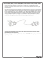
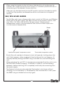
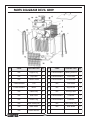
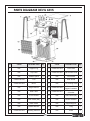
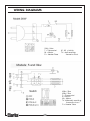
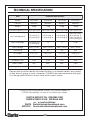
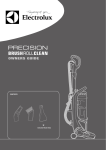
ELECTRIC FAN HEATERS
Devil 6003, 6005, 6009 & 6015
Part Nos: 6925220, 6925225, 6925230 & 6925235
OPERATING & MAINTENANCE
INSTRUCTIONS
GC0110
INTRODUCTION
Thank you for purchasing this CLARKE Electric Fan Heater.
Please read this manual thoroughly and follow the instructions carefully.
Before attempting to use the heater, thoroughly familiarise yourself with the
heater & its operation. In doing so you will ensure the safety of yourself and
that of others around you, and you can look forward to the heater giving you
long and satisfactory service.
GUARANTEE
This product is guaranteed against faulty manufacture for a period of 12
months from the date of purchase. Please keep your receipt which will be
required as proof of purchase.
This guarantee is invalid if the product is found to have been abused or
tampered with in any way, or not used for the purpose for which it was
intended.
Faulty goods should be returned to their place of purchase, no product can
be returned to us without prior permission.
This guarantee does not effect your statutory rights.
ENVIRONMENTAL PROTECTION
Do not dispose of this product with general household waste. It must
be disposed of according to the laws governing Waste Electrical and
Electronic Equipment, at a recognised disposal facility.
2
TABLE OF CONTENTS
INTRODUCTION .................................................................................. 2
GUARANTEE ........................................................................................ 2
ENVIRONMENTAL PROTECTION ......................................................... 2
TABLE OF CONTENTS .......................................................................... 3
GENERAL SAFETY RULES ..................................................................... 4
ELECTRICAL CONNECTIONS .............................................................. 6
OPERATION ......................................................................................... 8
MAINTENANCE ................................................................................... 10
FAULT FINDING ................................................................................... 11
PARTS LISTS & DIAGRAMS .................................................................. 12
WIRING DIAGRAMS ........................................................................... 16
TECHNICAL SPECIFICATION ............................................................... 18
SPARE PARTS & SERVICING CONTACTS ............................................. 18
DECLARATION OF CONFORMITY ....................................................... 19
3
GENERAL SAFETY RULES
1)
WORK AREA
1. These heaters are for INDOOR USE ONLY.
2. Do not expose the heater or power cable to rain or wet conditions. Any
water entering the heater will increase the risk of electric shock. DO NOT
use this heater in a bathroom, shower room, in the vicinity of a swimming
pool, or any wet environment.
3. NEVER locate the heater near combustible materials such as curtains,
furniture etc. Allow at least 1 metre clearance.
4. DO NOT locate the heater close to an adjacent wall or ceiling. Allow a
distance of at least 1 metre from a wall or ceiling. Avoid placing the
heater directly below socket outlets.
5. Take care to ensure that the grille cannot be blocked by curtains or other
fabrics.
6. Do not operate fan heaters in explosive atmospheres such as in the
presence of flammable liquids, gases or dust such as in a paint spray
booth or any explosive environment. Electric motors create sparks which
may ignite dust or fumes.
7. Never place the heater on a movable vehicle where it could be tipped
over.
8. Do not allow the heating elements to become covered with dust which
could become a fire hazard. If used in a dusty workplace it should be
cleaned as described under Cleaning and Maintenance.
9. NEVER touch the heater element for at least 15 minutes after switching off.
10. DO NOT leave the heater unattended.
11. If children are present always use with a fireguard.
12. Store the fan heater out of the reach of children and do not allow persons
unfamiliar with these instructions to operate this appliance.
13. Do not use this heater with a programmable timer used to switch it on
automatically.
2)
ELECTRICAL SAFETY
1. Electrical appliances must match the power outlet. Never modify the plug
in any way. Do not use adaptor plugs with earthed (grounded) appliances. Correct plugs and outlets will reduce the risk of electric shock.
2. Do not abuse the electrical cable. Never use the cord for pulling or
unplugging the heater. Keep the cable away from sources of heat, oil,
sharp edges or moving parts. Damaged or tangled cables increase the
risk of electric shock.
4
3. Keep the mains cable well away from machines and ensure an adequate
electrical supply is close at hand so that the operation is not restricted by
the length of the cable.
4. ALWAYS disconnect from the mains supply before moving the heater or
performing any maintenance tasks.
5. ALWAYS use ONLY in an upright position.
6. Inspect the mains cable regularly for signs of damage. DO NOT use if it is
damaged, and ALWAYS keep it away from the source of heat.
7. Check the fan heater for damage before use. DO NOT use if the heater
elements are damaged or broken. Any damage should be properly
repaired or the part replaced. If in doubt, DO NOT use the machine.
Consult your local dealer.
3)
SERVICE & REPAIRS
1. When necessary, have your appliance repaired by a qualified person
using identical replacement parts. This will ensure that the safety of the
appliance is maintained.
Additionally, please keep these instructions in a safe place for future
reference.
5
ELECTRICAL CONNECTIONS
DEVIL 6003 (3KW) HEATER UNIT
This model is provided with a 13 amp BS 1363 plug, fitted with a 13amp fuse and
MUST be connected to a standard, 230 Volt (50Hz) electrical supply, preferably
through an approved plug, or a suitably fused isolator switch.
E
WARNING: THIS APPLIANCE MUST BE EARTHED
IMPORTANT: The wires in the mains lead should be wired up in accordance
with the following colour code:
Green & Yellow -
Earth
Blue
-
Neutral
Brown
-
Live
As the colours of the flexible cable of this appliance may not correspond with
the coloured markings identifying terminals in your plug, proceed as follows:
•
Connect the GREEN & YELLOW coloured cord to the plug
terminal marked with a letter E or Earth symbol “
” or coloured
GREEN or GREEN & YELLOW.
•
Connect the BROWN coloured cord to the plug terminal
marked a letter “L” or coloured RED.
•
Connect the BLUE coloured cord to the plug terminal marked
a letter “N” or coloured BLACK
If this appliance is found to be fitted with a plug which is moulded on to the
electric cable (i.e. non-rewireable) please note:
1. The plug must be thrown away if it is cut from the electric cable. There is a
danger of electric shock if it is subsequently inserted into a socket outlet.
2. Never use the plug without the fuse cover fitted.
3. Should you wish to replace a detachable fuse carrier, ensure that the
correct replacement is used (as indicated by marking or colour code).
4. Replacement fuse covers can be obtained from your local Clarke dealer
or most electrical stockists.
FUSE RATING
The fuse in the plug must be replaced with one of the same rating and this
replacement must be ASTA approved to BS1362.
We strongly recommend that this machine is connected to the mains supply
via a Residual Current Device (RCD).
6
DEVIL 6005 (5KW), DEVIL 6009(9KW) AND DEVIL 6015(15KW) UNITS
These machines MUST be connected to a 400 Volt, 3 PHASE 50Hz supply
through a suitably fused isolator switch. It cannot be operated from a single
phase supply.
The user should purchase a suitable connecting lead as shown in the diagram,
which is compatible with the appliance socket. The unit requires 5 pins including a master earth pin, and is suitable for AC 380/415v, 50/60Hz with a capacity of 16A/6h (Devil 6005 and 6009) or 32A/6h (Devil 6015) and rated at IP44
class or better insulation. A length of 2-3 metres is recommended as giving
mobility to the appliance but without becoming a trip hazard.
The plug incorporates a hood which will secure the cable in position when
engaged with the appliance.
If in any doubt, consult a qualified electrician. DO NOT attempt any electrical
repairs yourself.
7
OPERATION
The Devil range of fan assisted electric heaters are suitable for household
(Devil 6003 only) or workshop/factory use. They incorporate a thermostat
which detects the temperature of the room air and controls the heater to
maintain a pre-selected temperature between 0 & 40°C. A manually reset
thermal cutout is provided for safety in the event of overheating on the 6005,
6009 & 6015 models. The fan motor runs independently of the thermostat and
continues running after the heating element has been switched off.
With the heater suitably sited (ensure you comply with all safety precautions),
switch the heater ON to the chosen setting as follows:
3 KW HEATERS
The 3kw heater has 3 running speeds for the fan incorporating 2 settings for
both of the heating elements once the fan is set running. The other control is
a progressive thermostat which is rotated through 270 deg. A cutout is used
to maintain a constant pre-set temperature.
3-position fan speed control
thermostatic temperature control
When using the heater to warm a cold room, first turn the thermostat to MAX
and run the heater on full power until the room temperature reaches the
required value, then turn the thermostat anti-clockwise until it switches off.
The thermostat will then switch the heater on and off automatically to control
the room temperature according to the pre-set value, maintaining a constant room temperature. The 3kw unit is fitted with a self-resetting thermal
cutout.
8
When using the heater for the first time a slight emission of smoke may be
noticed. This is quite normal and soon stops. It is caused by residual traces of
oil remaining on the element from production.
After use, turn the thermostat to the OFF position and turn the selector switch
to the Fan Only position, and leave the unit to cool down for a couple of
minutes.
5KW, 9KW &15KW HEATERS
The 5 & 9kw units have a three position twist control for FAN only, and FAN plus
either half or full heat output. The 15kw unit has a four position control;- FAN
only, FAN + 1/3, FAN + 2/3 & FAN + full heat output. A thermostatic
temperature control is also provided for fine control of heat output at a
constant pre-set temperature.
Reset
Thermostatic temperature control
3-position fan speed / temperature control
Should the unit overheat, a thermal cutout will operate, shutting down the
unit. If this happens, allow a period of time for the unit to cool (approx. 10
minutes) before pressing the RESET using a suitable tool, and restarting the
unit.
When switching the unit OFF, it is strongly recommended that the unit is run in
the FAN ONLY mode for approx. 10 minutes, in order to cool the heating
elements, before switching OFF completely and finally disconnecting from
the mains supply.
The thermal cutout may also operate if the heater is shut down without
allowing to cool sufficiently. If, subsequently, the machine fails to start, press
the RESET using a suitable tool and try again.
9
MAINTENANCE
If the heater has been used, ALWAYS allow it to cool down for at least 10
minutes (by switching the heater OFF, but leave the fan running), then
disconnect from the mains supply before performing any maintenance tasks.
PERIODICALLY
• Disconnect from the mains supply, and use compressed air to clean
out the unit. ALWAYS wear a dust mask to perform this operation.
• If there is any serious build up of dirt, wipe thoroughly with a damp
cloth. Take care that no moisture enters the heater.
• Inspect the mains cable for damage. Heat damage will cause the
cable to stiffen and crack. If this is found, have the cable replaced.
Check cable routing and ensure it is well away from the heat
source.
• Ensure heating elements are clear of dust (use compressed air to
clean the heater if possible).
• Avoid using solvents when cleaning plastic parts, most plastics are
susceptible to damage from various types of commercial solvents.
• Refer to your CLARKE dealer if internal maintenance is required. The
unit is fitted with tamper-proof screws to discourage users from
dismantling the heater.
• When storing the heater, allow it to cool down, then cover it with its
plastic bag and place it in its packing box for storage in a dry,
ventilated place.
10
FAULT FINDING
Problem
Possible cause
Plug is loose/bad
connection.
Heater does not
operate, although
plugged in with the
Fuse blown
switch and ther mostat
switched on.
The unit failed to heat
up so only the air fan
operated.
Pull the plug out & check the
connection of the plug and
socket.
Replace if necessary and
investigate cause. If fuse
b l o w s re p e a t e d l y , c o n s u l t
your CLARKE dealer.
No power at socket
outlet.
Heating element
glowing hot.
Remedy
Insert the plug in a suitable
socket.
Use a power supply in
I n p u t v o l t a g e t o o h i g h a c c o rd a n c e w i t h t h e r a t i n g
or too low.
on the label.
Air inlet grille is
blocked.
E n s u re t h e h e a t e r i s k e p t a w a y
f ro m a n y o b j e c t s w h i c h c o u l d
cover the air inlet or be
drawn into it.
C o n t ro l s w i t c h n o t s e t
at a "HEATING" level.
Tur n switch to a heating level.
Ther mostat has
tripped.
Tur n the ther mostat and listen.
I f t h e re i s n o C L I C K a n d t h e
ther mostat is not damaged,
the heater will automatically
switch ON when it has cooled
down.
Disconnect the power. Take a
suitable pin and insert it into
the manual RESET hole in the
T h e m a n u a l l y re s e t
c u t - o u t h a s o p e r a t e d . c o n t ro l p a n e l . P re s s t h e R E S E T
button and connect the
c i rc u i t .
Abnor mal noise.
The appliance is not
level.
11
Stand heater on a level
sur face.
PARTS DIAGRAM DEVIL 6003
NO
CODE
DESCRIPTION
Qty
NO
CODE
DESCRIPTION
Qty
1
N/A
Support Leg
2
13
C X D E V 600305
Front Grille
1
2
N/A
Top Panel
1
14
C X D E V 600306
Fan Control Knob
1
3
N/A
Chassis panel
1
15
N/A
Front Panel
1
4
C X D E V 600301
F an
1
16
N/A
Mounting Packer
2
5
C X D E V 600302
Motor
1
17
N/A
Washer
1
6
N/A
Retaining clips
2
18
C X D E V 600307
Power/Fan Speed
Controller
1
7
N/A
Rear Panel
1
19
C X D E V 600308
Temperature
Controller
1
8
C X D E V 600303
Power Cable
1
20
N/A
Side Panel (LH)
1
9
N/A
Side Panel (RH)
1
21
N/A
Air Duct
1
10
N/A
Base Panel
1
22
C X D E V 600309
Thermal Cutout
1
11
N/A
Heater Bracket
1
23
C X D E V 600310
Terminal Block
1
12
C X D E V 600304
Heating Element
2
12
PARTS DIAGRAM DEVIL 6005
NO
CODE
DESCRIPTION
Qty
NO
CODE
DESCRIPTION
Qty
1
N/A
Support Leg
2
13
C X D E V 600504
Front Grille
1
2
N/A
Top Panel
1
14
C X D E V 600505
Fan Control Knob
1
3
N/A
Chassis panel
1
15
N/A
Front Panel
1
4
C X D E V 600501
F an
1
16
N/A
Plastic Plug
1
5
C X D E V 600502
Motor
1
17
N/A
Support Bar
1
1
6
N/A
5-Pin Socket
1
18
C X D E V 600506
Power/Fan Speed
Controller
7
N/A
Rear Panel
1
19
C X D E V 600507
Temperature
Controller
1
8
N/A
Cable Entry
1
20
N/A
Side Panel (LH)
1
9
N/A
Side Panel (RH)
1
21
N/A
Heat Shield
2
10
N/A
Base Panel
1
11
N/A
Heater Bracket
1
12
C X D E V 600503
Heating Element
2
13
PARTS DIAGRAM DEVIL 6009
NO
CODE
DESCRIPTION
Qty
NO
CODE
DESCRIPTION
Qty
1
N/A
Support Leg
2
12
C X D E V 600903
Heating Element
2
2
N/A
Top Panel
1
13
C X D E V 600904
Front Grille
1
3
N/A
Chassis Panel
1
14
C X D E V 600905
Control Knob
2
4
C X D E V 600901
F an
1
15
N/A
Front Panel
1
5
C X D E V 600902
Motor
1
16
N/A
Support Bar
1
6
N/A
Cable Entry
2
17
N/A
Closing Panel
1
7
N/A
Rear Panel
1
18
C X D E V 600907
Power/Fan Speed
Controller
1
8
N/A
Plastic Plug
1
19
C X D E V 600908
Temperature
Controller
1
9
N/A
Side Panel (RH)
1
20
N/A
Side Panel (LH)
1
10
N/A
Base Panel
1
21
N/A
Heat Shield
2
11
N/A
Heater Bracket
1
14
PARTS DIAGRAM DEVIL 6015
NO
CODE
DESCRIPTION
Qty
NO
CODE
DESCRIPTION
Qty
1
N/A
Support Leg
2
13
C X D E V 601504
Front Grille
1
2
N/A
Top Panel
1
14
C X D E V 601505
Fan Control Knob
1
3
N/A
Chassis panel
1
15
N/A
Front Panel
1
4
C X D E V 601501
F an
1
16
N/A
Heat Shield
2
5
C X D E V 601502
Motor
1
17
N/A
Fan Closing Plate
1
6
N/A
Angle Bracket
1
18
C X D E V 601506
Power / Fan
Speed Controller
1
7
N/A
Rear Panel
1
19
C X D E V 601507
Temperature
Controller
1
8
N/A
5-Pin Socket
1
20
N/A
Side Panel (LH)
1
9
N/A
Side Panel (RH)
1
21
N/A
Heater Retainer
2
10
N/A
Base Panel
1
22
N/A
Supporting bar
1
11
N/A
Heater Bracket
1
23
N/A
Plug
1
12
C X D E V 601503
Heating Element
6
24
N/A
Bush
2
15
WIRING DIAGRAMS
230v / 3kw
T = Thermostat
M = Motor
D = Heater Tube
K1, K2 = Switch
TV = Self resetting
themal cut-out
400v / 5kw
400v / 9kw
T = Thermostat
B = Switch
M = Motor
TV =Manually resetting
thermal cut-out
D = Heater Tube
16
WIRING DIAGRAMS
400v / 15kw
T = Thermostat
B = Switch
M = Motor
TV=Manually resetting
thermal cut-out
D =Heater Tube
17
TECHNICAL SPECIFICATION
Item
Published Specification
Model
Devil 6003
Devil 6005
Devil 6009
Devil 6015
Part No
6925220
6925225
6925230
6925235
Weight
5.5kg
7.0kg
9.0kg
14.4kg
295 x 305 x 425
350 x 335 x 465
400 x 345 x 535
Input Wattage(kw)
1.5 (setting 1)
3.0 (setting 2)
2.5 (setting 1)
5.0 (setting 2)
4.5 (setting 1)
9.0 (setting 2)
95w (fan only)
5kw (setting 1)
10kw (setting 2)
15kw (setting 3)
Input Amperage
6.39 (setting 1)
12 (setting 2)
7.2
13
21.65
Input Voltage
230v / 50 Hz
400v / 50 Hz
400v / 50 Hz
400v / 50 Hz
Fuse rating
13A
16A
16A
32A
Air Output
512 m3/h
557 m3/h
773 m3/h
1559 m3/h
Sound Level
51 or<70dB (A)
51 or<70dB (A)
59 or<70dB (A)
64 or<70dB (A)
Insulation Class
IPX4
IPX4
IPX4
IPX4
Heat Output
3kw
5kw
9kw
15kw
Operating Temperature
0-40°C
0-40°C
0-40°C
0-40°C
Dimensions (dxwxh) mm 295 x 265 x 425
Please note that the details and specifications contained herein, are correct
at the time of going to print. However, CLARKE International reserve the right
to change specifications at any time without prior notice.
For parts & Servicing, please contact your nearest dealer, or
CLARKE International, on one of the following numbers.
PARTS & SERVICE TEL: 020 8988 7400
PARTS & SERVICE FAX: 020 8558 3622
or e-mail as follows:
PARTS: [email protected]
SERVICE: [email protected]
18
DECLARATION OF CONFORMITY
DECLARATION OF CONFORMITY
This is an important document and should be retained.
We declare that this product complies with the following directives:
2004/108/EC
Electromagnetic Compatibility directive
2006/95/EC
Low Voltage Equipment directive
2002/95/EC
Restriction of Hazardous substances
The Following Standards have been applied to the product:
EN 55014-1:2000/A1:2001/+A2:2002
EN 55014-2 1997/+A1:2001
EN 61000-3-2:2000/+A2:2005
EN 61000-3-3:1995+A1:2001/+A2:2005
EN 60335-1:2002+A11,A1:04+A12+,A2:06
EN 60335-2-30:2003+A1:04
EN 50366:2003+A1:06
The technical documentation required to demonstrate that the products meet the
requirements of the Low Voltage Equipment directive has been compiled and is available
for inspection by the relevant enforcement authorities.
The CE mark was first applied in: 2007
Product Description:
Electric Fan Heaters (3kW, 5kW, 9kW,15kW )
Model number(s):
Devil 6003,6005,6009,6015
Serial / batch Number:
Current Manufacture.
Date of Issue:
02/09/2008
Signed
A.C. AIKEN
Senior Manager Clarke International.
ELECTRIC HEATERS-TEC SPEC-DOC- RV1.doc
Page 1 of 1
19