1
OPERATING INSTRUCTIONS
CLV 490
Bar Code Scanner
Advanced line
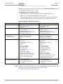
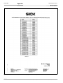
Software versions
Operating Instructions
CLV 490 Bar Code Scanner
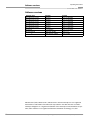
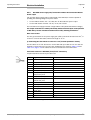
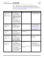
Software versions
Software/Tool
Function
Version
CLV 490-0010/-0011
Firmware
From V 0.90 0000
CLV 490-1010/-1011
Firmware
From V 0.90 0000
CLV 490-6010/-6011
Firmware
From V 1.22 K609
CLV 490-7010/-7011
Firmware
From V 1.22 K609
CLV 490-2010/-2011
Firmware
From V 1.30 KA54
CLV 490-3010/-3011
Firmware
From V 1.30 KA54
CLV-Setup
User interface
From V 2.70 J645
CLV-Setup Help
Online help (HTML)
From V 1.1
I-ViewProTM
HTML browser (offline)
From V 2.38
Windows 95TM/98TM, Windows NTTM, Windows XPTM and Internet ExplorerTM are registered
trademarks or trademarks of the Microsoft Corporation in the USA and other countries.
Netscape NavigatorTM is a registered trademark of the Netscape Communications Cooperation, USA. I-ViewProTM is a registered trademark of EnReach Technology, Inc., USA.
I-2
© SICK AG · Division Auto Ident · Germany · All rights reserved
8 008 796/0000/25-06-2002
Operating Instructions
Quick Finder
CLV 490 Bar Code Scanner
CLV 490 Bar Code Scanner
Quick Finder
•
What is delivered with the device
– Chapter 3.1.1 Scope of delivery, Page 3-1
•
CAUTION!
– Chapter 2 Safety information, Page 2-1
•
Mounting the device at the reading station
– Chapter 4 Installation, Page 4-1
•
Connecting the device
– Chapter 5 Electrical installation, Page 5-1
•
Overview of the device and its functions
– Chapter 3 Product description, Page 3-1
– Chapter 6.2 Default settings, Page 6-1
– Chapter 6.5 Operating modes and outputing the reading result, Page 6-19
– Chapter 9 Technical data, Page 9-1
– Chapter 10.3 Installing and operating the external parameter memory, Page 10-34
•
Starting the device with the default settings
– Chapter 6.3 Quick start, Page 6-3
•
Installing the "CLV-Setup" program
– Chapter 10.6 Installing and operating the "CLV-Setup" program, Page 10-41
•
Adapting the device to the reading application
– Chapter 6.4 Configuring (parameterization) the CLV, Page 6-5
•
Troubleshooting
– Chapter 8 Troubleshooting, Page 8-1
•
Finding information
– Table of contents, Page I-5
– Index, Page 10-85
8 008 796/0000/25-06-2002
© SICK AG · Division Auto Ident · Germany · All rights reserved
I-3
Quick Finder
Operating Instructions
CLV 490 Bar Code Scanner
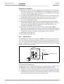
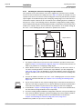
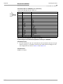
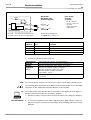
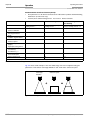
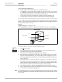
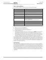
Installation procedure (overview)
Reading trigger via “Sensor“ switching input (default setting)
1.
Check the delivery to make sure that none of the components is missing.
2.
Mount the CLV at the reading station and align it with the object carrying the bar code.
3.
Mount the AMV/S 60 Connection Module.
4.
Connect the CLV to the AMV/S 60 Connection Module using the two cables
no. 2 020 302.
Alternatively, connect the device to the AMV/S 60 via the external parameter memory
no. 2 020 307.
5.
Connect the reading pulse sensor to the "Sensor" switching input in the AMV/S 60.
6.
Connect the host to the host interface in the AMV/S 60.
Adapt the AMV/S 60 to the host interface type of the CLV.
7.
Switch on the power supply to the AMV/S 60.
The "Device Ready" LED lights up after the CLV has started.
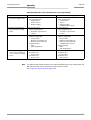
CLV with external parameter memory connected:
The "Device Ready" LED and the "Read Result" LEDs blink after the CLV has started.
The CLV is not ready to start reading. See step 11.
Line scanner with oscillating mirror:
In the default setting, the CLV deflects the scan line around the position CW = 50 with
a frequency of 1 Hz and an oscillating amplitude of max. ±20° (±40 CW).
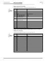
8.
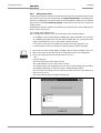
Switch on your PC and start WindowsTM (minimum requirement: Windows 95TM).
9.
Install the "CLV-Setup" software, online CLV-Setup Help and, if necessary, the
I-ViewProTM HTML browser from the CD on your PC.
10. Connect the PC to the terminal interface of the CLV. To do so, connect the RS 232 data
connection cable (e. g. no. 2 014 054) to the "Service plug" in the AMV/S 60.
11. Start the "CLV-Setup" program.
CLV-Setup establishes communication with the CLV and uploads the parameter set.
The parameters are then displayed on the tabs.
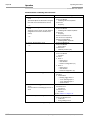
CLV with external parameter memory connected:
First download the CLV parameter set to the external memory.
Disconnect the AMV/S 60 briefly from the power supply to restart the CLV.
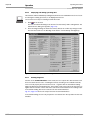
12. Carry out a test read using test bar codes (clock the CLV accordingly).
Display the reading result in the Terminal Emulator window of the "CLV-Setup" program.
13. Configure the CLV for the application using the settings on the tabs in CLV-Setup.
Copy (download) the modified parameter set to the CLV temporarily.
Do not switch off the power to the AMV/S 60 (CLV)!
14. Test the application under realistic conditions.
15. Check whether the data is transmitted correctly between the CLV and host.
16. If necessary, correct and optimize the parameter values.
Copy (download) the parameter set permanently to the CLV.
CLV with external parameter memory connected:
Copy the modified parameter set to the external parameter memory.
17. Save the parameter set as a configuration file "*.scl" in the "CLV-Setup" program.
The CLV can then be operated with the application-specific settings.
I-4
© SICK AG · Division Auto Ident · Germany · All rights reserved
8 008 796/0000/25-06-2002
Operating Instructions
Contents
CLV 490 Bar Code Scanner
Table of contents
1
1.1
1.2
1.2.1
1.2.2
1.3
1.4
2
2.1
2.1.1
2.1.2
2.1.3
2.2
2.3
2.4
2.4.1
2.4.2
2.5
2.5.1
2.5.2
3
3.1
3.1.1
3.1.2
3.1.3
3.1.4
3.2
3.2.1
3.2.2
3.2.3
3.2.4
3.3
3.3.1
3.3.2
4
4.1
4.2
4.2.1
4.2.2
4.2.3
4.2.4
4.2.5
4.2.6
4.2.7
4.2.8
4.3
4.3.1
4.3.2
4.3.3
4.4
4.4.1
4.4.2
4.4.3
4.5
5
8 008 876/0000/25-06-2002
Notes on this document............................................................................................ 1-1
Purpose ....................................................................................................................................... 1-1
Target audience........................................................................................................................ 1-1
Mounting, electrical installation, maintenance and replacement.................... 1-1
Startup, operation and configuration ......................................................................... 1-1
Information content................................................................................................................. 1-2
Symbols ....................................................................................................................................... 1-2
Safety information....................................................................................................... 2-1
Authorized users ...................................................................................................................... 2-1
Mounting and maintenance .......................................................................................... 2-1
Electrical installation and replacement ..................................................................... 2-1
Startup, operation and configuration ......................................................................... 2-1
Intended use.............................................................................................................................. 2-1
General safety instructions and protection measures .............................................. 2-1
Quick stop and quick restart................................................................................................ 2-3
Stopping the CLV............................................................................................................... 2-3
Restarting the CLV ............................................................................................................ 2-3
Environmental information.................................................................................................... 2-4
Power requirements......................................................................................................... 2-4
Disposal after removal from service.......................................................................... 2-4
Product description .................................................................................................... 3-1
Design .......................................................................................................................................... 3-1
Scope of delivery............................................................................................................... 3-1
Variants ................................................................................................................................. 3-1
System requirements ...................................................................................................... 3-2
Design ................................................................................................................................... 3-4
Method of operation............................................................................................................... 3-5
Autofocus function............................................................................................................ 3-6
Event-controlled dynamic focus control ................................................................... 3-7
Scan procedure variants ................................................................................................ 3-7
Additional components ................................................................................................... 3-8
Indicators and control elements ........................................................................................ 3-8
Control elements............................................................................................................... 3-8
Function of the LEDs........................................................................................................ 3-8
Installation..................................................................................................................... 4-1
Installation sequence ............................................................................................................. 4-1
Preparations............................................................................................................................... 4-1
Required components..................................................................................................... 4-1
Required accessories...................................................................................................... 4-1
Required auxiliary parts .................................................................................................. 4-1
Replacing the laser warning label ............................................................................... 4-2
Selecting the mounting location .................................................................................. 4-2
Mounting accessories ..................................................................................................... 4-3
Distance between the CLV and the bar code........................................................ 4-4
Count direction of the code position CP and code angle CW.......................... 4-6
Mounting and adjusting the device................................................................................... 4-7
Mounting the CLV.............................................................................................................. 4-7
Adjusting the CLV .............................................................................................................. 4-8
Adjusting mode .................................................................................................................. 4-9
Mounting the external components................................................................................4-10
Mounting the AMV/S 60 Connection Module......................................................4-10
Mounting the external reading pulse sensor........................................................4-10
Mounting the sensors for detecting the object distance.................................4-12
Dismantling the device ........................................................................................................4-13
Electrical installation ................................................................................................. 5-1
© SICK AG · Division Auto Ident · Germany · All rights reserved
I-5
Contents
Operating Instructions
CLV 490 Bar Code Scanner
5.1
Installation sequence............................................................................................................. 5-1
5.1.1
SICK Connection Modules (overview)......................................................................5-1
5.2
Electrical connections and cables .....................................................................................5-2
5.2.1
Wire cross-sections ..........................................................................................................5-2
5.2.2
Prefabricated cables (overview) ..................................................................................5-2
5.2.3
Connections/cables for the AMV/S Connection Module ................................... 5-3
5.2.4
Connections/cables for the Bus Connection Modules
BMV 10 and BMS 20 ......................................................................................................5-4
5.2.5
Connections/cables for the external parameter memory
(connection to AMV/S or BMV 10/BMS 20) ..........................................................5-4
5.2.6
Connections/cables for the IP 65 connector cover
(connection to AMV 100/200 or BMV 10).............................................................5-5
5.3
Connector pin assignment.................................................................................................... 5-6
5.3.1
Terminals on the CLV.......................................................................................................5-6
5.3.2
External parameter memory no. 2 020 307/2 021 689
(optional accessory)
connector cover no. 2 021 298 (optional accessory) .......................................5-7
5.4
Preparations for electrical installation...............................................................................5-8
5.4.1
Requirements for the host interface ..........................................................................5-8
5.4.2
Supply voltage ....................................................................................................................5-8
5.4.3
Non-SICK Power supply unit/connections without the Connection Module5-9
5.5
Electrical installation procedure ....................................................................................... 5-13
5.5.1
Individual steps................................................................................................................ 5-13
5.5.2
Tools .................................................................................................................................... 5-13
5.5.3
Connecting the supply voltage .................................................................................. 5-13
5.5.4
Connecting the host interface ................................................................................... 5-14
5.5.5
Connecting the CAN interface ................................................................................... 5-15
5.5.6
Connecting the PC.......................................................................................................... 5-15
5.5.7
Connecting the switching inputs ............................................................................... 5-16
5.5.8
Connecting the "Result 1 Result 4" switching outputs .................................... 5-19
6
Operation ....................................................................................................................... 6-1
6.1
Overview of steps for starting up the CLV ......................................................................6-1
6.2
Default settings ......................................................................................................................... 6-1
6.2.1
Default settings of the line scanner CLV 490 (all variants)...............................6-2
6.2.2
Default settings of the line scanner with oscillating mirror
CLV 490 (all variants) ......................................................................................................6-2
6.3
Quick start ...................................................................................................................................6-3
6.3.1
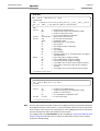
Switching the CLV on for the first time with the factory default settings......6-3
6.3.2
Switching the CLV with external parameter memory connected on
for the first time with the factory default settings .................................................6-4
6.4
Configuring (parameterization) the CLV........................................................................... 6-5
6.4.1
Configuring the CLV via the user interface of CLV-Setup................................... 6-5
6.4.2
Function of the tabs in CLV-Setup (overview) ........................................................6-6
6.4.3
Parameterizing example .................................................................................................6-8
6.4.4
Guide to parameterization menu................................................................................. 6-8
6.5
Operating modes and outputing the reading result ................................................. 6-19
6.5.1
Reading mode (standard operating mode).......................................................... 6-19
6.5.2
Percentage evaluation.................................................................................................. 6-22
6.5.3
Adjusting mode................................................................................................................ 6-24
6.5.4
Background teach-in ..................................................................................................... 6-25
6.5.5
Show CP-limits ................................................................................................................. 6-26
6.5.6
Displaying and editing operating data .................................................................... 6-28
6.5.7
Reading diagnosis .......................................................................................................... 6-28
6.5.8
Monitor Host Interface.................................................................................................. 6-29
6.5.9
Auxiliary input.................................................................................................................... 6-31
6.5.10 Self-test .............................................................................................................................. 6-31
6.5.11 Executing CLV functions interactively...................................................................... 6-32
I-6
© SICK AG · Division Auto Ident · Germany · All rights reserved
8 008 876/0000/25-06-2002
Operating Instructions
Contents
CLV 490 Bar Code Scanner
6.6
CLV messages ........................................................................................................................6-33
6.6.1
Displaying messages.....................................................................................................6-33
6.6.2
System messages ..........................................................................................................6-33
6.6.3
Warning messages.........................................................................................................6-33
6.6.4
Error messages ...............................................................................................................6-33
6.7
Switching off the CLV............................................................................................................6-34
7
Maintenance ................................................................................................................. 7-1
7.1
Cleaning the CLV during operation.................................................................................... 7-1
7.2
Maintenance.............................................................................................................................. 7-2
7.3
Disposal....................................................................................................................................... 7-2
8
Troubleshooting ........................................................................................................... 8-1
8.1
Overview of the possible errors and malfunctions...................................................... 8-1
8.1.1
Mounting errors ................................................................................................................. 8-1
8.1.2
Electrical installation errors............................................................................................ 8-1
8.1.3
Parameter errors............................................................................................................... 8-1
8.1.4
Malfunctions........................................................................................................................ 8-1
8.2
Monitoring error and malfunctions .................................................................................... 8-1
8.3
Error messages ........................................................................................................................ 8-2
8.3.1
CLV without external parameter memory................................................................ 8-2
8.3.2
LED error messages for the external parameter memory................................ 8-5
8.3.3
Messages for errors accessing the external parameter memory ................. 8-7
8.4
ST error status in the reading result of a bar code..................................................... 8-9
8.5
Troubleshooting......................................................................................................................8-10
8.5.1
General malfunctions: CLV not ready......................................................................8-10
8.5.2
Malfunctions in Reading mode: reading trigger errors......................................8-11
8.5.3
Malfunctions in Reading mode: result output errors .........................................8-12
8.5.4
Malfunctions in Reading mode: errors in the result status output...............8-14
8.5.5
Malfunctions in Reading mode: oscillating mirror errors..................................8-15
8.6
SICK Support ...........................................................................................................................8-15
9
Technical data .............................................................................................................. 9-1
9.1
Data sheet CLV 490-0010/-2010/-6010 bar code scanner............................... 9-1
9.2
Data sheet CLV 490-1010/-3010/-7010 bar code scanner............................... 9-2
9.3
Data sheet CLV 490-0011 /-2011/-6011 bar code scanner.............................. 9-2
9.4
Data sheet CLV 490-1011/-3011/-7011 bar code scanner............................... 9-3
9.5
Dimensioned drawings – CLV............................................................................................. 9-3
9.5.1
Line scanner (standard device) without /with heater ......................................... 9-3
9.5.2
Line scanner with oscillating mirror (without/with heater)................................. 9-4
10
Appendix ..................................................................................................................... 10-1
10.1 Overview....................................................................................................................................10-1
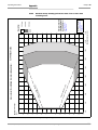
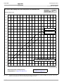
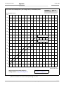
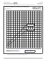
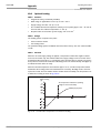
10.2 Specification diagrams.........................................................................................................10-1
10.2.1 Reading conditions for all diagrams .........................................................................10-1
10.2.2 Overview of diagrams ....................................................................................................10-2
10.2.3 Standard density: Reading performance data of line scanner......................10-3
10.2.4 Standard density: Reading performance data of line scanner
with oscillating mirror .....................................................................................................10-9
10.2.5 High density: Reading performance data of line scanner ............................10-16
10.2.6 High density: Reading performance data line scanner with
oscillating mirror............................................................................................................10-21
10.2.7 Low density: Reading performance data of line scanner .............................10-27
10.2.8 Low density: Reading performance data of line scanner with
oscillating mirror............................................................................................................10-31
10.3 Installing and operating the external parameter memory...................................10-34
10.3.1 Function ...........................................................................................................................10-34
10.3.2 Installation and electrical connection ...................................................................10-35
10.3.3 Operation.........................................................................................................................10-35
10.3.4 Switching on the device for the first time ...........................................................10-36
10.3.5 Adjusting the parameter set in the external parameter memory
8 008 876/0000/25-06-2002
© SICK AG · Division Auto Ident · Germany · All rights reserved
I-7
Contents
Operating Instructions
CLV 490 Bar Code Scanner
after it has been downloaded to the CLV .......................................................... 10-36
10.3.6 Meaning of the LEDs.................................................................................................. 10-37
10.3.7 Error messages............................................................................................................ 10-37
10.3.8 Replacing a CLV ........................................................................................................... 10-37
10.4 Optional heating .................................................................................................................. 10-38
10.4.1 Features .......................................................................................................................... 10-38
10.4.2 Design.............................................................................................................................. 10-38
10.4.3 Function........................................................................................................................... 10-38
10.4.4 Electrical installation ................................................................................................... 10-39
10.4.5 Outdoor applications .................................................................................................. 10-39
10.5 System messages ............................................................................................................. 10-40
10.5.1 CLV without external parameter memory .......................................................... 10-40
10.5.2 CLV with external parameter memory connected .......................................... 10-40
10.6 Installing and operating the "CLV-Setup" program................................................ 10-41
10.6.1 Preparations .................................................................................................................. 10-41
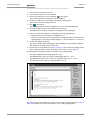
10.6.2 Installing the software................................................................................................ 10-41
10.6.3 Starting CLV-Setup...................................................................................................... 10-43
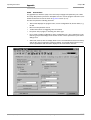
10.6.4 User interface................................................................................................................ 10-45
10.6.5 Functions ........................................................................................................................ 10-46
10.6.6 CLV-Setup Help ............................................................................................................ 10-46
10.6.7 Transferring parameter sets between CLV-Setup and the CLV ................ 10-47
10.6.8 Unknown parameters................................................................................................. 10-47
10.6.9 Log file in the Terminal Emulator ........................................................................... 10-48
10.6.10 Starting CLV-Setup with an "INI file" as an argument.................................... 10-48
10.6.11 The CLV Assistant........................................................................................................ 10-48
10.7 Configuring a CLV with command strings.................................................................. 10-49
10.8 Calculating parameter values for setting the CLV.................................................. 10-51
10.8.1 Calculating the number of scans (for standard decoders).......................... 10-51
10.8.2 Calculating the start position and mirror speed for the forward
and return phase of the One-Shot function ...................................................... 10-53
10.8.3 Calculating the necessary bar code distance if several bar
codes are read on each object.............................................................................. 10-54
10.9 Tables ..................................................................................................................................... 10-55
10.9.1 Calculating the code length of a bar code......................................................... 10-55
10.10 Discussion of a parameterization example .............................................................. 10-56
10.10.1 Application Conditions ............................................................................................... 10-56
10.10.2 Purpose of this discussion ....................................................................................... 10-56
10.10.3 Instructions for solution – step by step .............................................................. 10-56
10.10.4 Important clarifications .............................................................................................. 10-57
10.10.5 Mounting and electrical connection ..................................................................... 10-57
10.10.6 Parameterize the CLV with the "CLV-Setup" program .................................. 10-58
10.10.7 Testing the application .............................................................................................. 10-64
10.11 Special applications and procedures ......................................................................... 10-65
10.11.1 Auxiliary input................................................................................................................. 10-65
10.11.2 Daisy-chain configuration
(data forwarding or master/slave arrangement)............................................. 10-68
10.11.3 SICK network (RS 485)............................................................................................. 10-68
10.11.4 Connection to Profibus DP ....................................................................................... 10-68
10.11.5 Connection to the DeviceNet.................................................................................. 10-68
10.11.6 Connection to Interbus-S.......................................................................................... 10-68
10.11.7 Connection to Ethernet ............................................................................................. 10-68
10.11.8 Building a CAN scanner network ........................................................................... 10-68
10.11.9 Integration in an OPS reading system ................................................................. 10-68
10.12 Replacing a CLV (copying the parameter set)......................................................... 10-69
10.12.1 Downloading the parameter set ............................................................................ 10-69
10.12.2 Importing the parameter set from the external memory ............................. 10-70
10.13 Accessories .......................................................................................................................... 10-71
I-8
© SICK AG · Division Auto Ident · Germany · All rights reserved
8 008 876/0000/25-06-2002
Operating Instructions
Contents
CLV 490 Bar Code Scanner
10.13.1 Mounting accessories ................................................................................................10-71
10.13.2 Connection modules...................................................................................................10-71
10.13.3 Bus connection modules ..........................................................................................10-71
10.13.4 Cables, external parameter memories and plug cover.................................10-73
10.13.5 Plug-in connections .....................................................................................................10-74
10.13.6 Reading pulse generators.........................................................................................10-74
10.13.7 Network controller .......................................................................................................10-74
10.14 Dimensioned drawings of the accessories...............................................................10-75
10.14.1 Angle bracket, single no. 2 013 824 ...................................................................10-75
10.14.2 Articulated bracket No. 2 018 435 ......................................................................10-75
10.14.3 Quick clamping device No. 2 016 110 ...............................................................10-75
10.15 Supplementary documentation .....................................................................................10-76
10.16 Glossary..................................................................................................................................10-77
10.17 Copy of the EC Declaration of Conformity.................................................................10-85
10.18 Index ........................................................................................................................................10-87
10.19 Bar code example ..............................................................................................................10-91
8 008 876/0000/25-06-2002
© SICK AG · Division Auto Ident · Germany · All rights reserved
I-9
Figures and tables
Operating Instructions
CLV 490 Bar Code Scanner
Abbreviations
AMV/S
Connection Module with signal distribution/with additional power supply pack
BMV/S
Bus Connection module with signal distribution/with additional power supply
CAN
Controller Area Network (standard field bus system with message-orientated data exchange protocol)
CLV
Code-Leser V-Prinzip.
The CLV 490 bar code scanners are abbreviated to "CLV" in this documentation, exept where a distinction is necessary
DC
DOF
EEPROM
HD
HTML
Distance Configuration
Depth Of Field
Electrically Erasable Programmable Read Only Memory
High Density
Hyper Text Markup Language (page-description language on the internet)
LED
Light Emitting Diode
PLC
Programmable Logic Controller
RAM
Ramdom Acces Memory
ROM
Read Only Memory
RTF
SMART
Rich Text Format (standard document format with format descriptions)
SICK Modular Advanced Recognition Technology
Tables
Table 3-1:
Table 3-2:
Table 3-3:
Table 4-1:
Table 5-1:
Table 5-2:
Table 5-3:
Table 5-4:
Table 5-5:
Table 5-6:
Table 5-7:
Table 5-8:
Table 5-9:
Table 5-10:
Table 5-11:
Table 5-12:
Table 5-13:
Table 5-14:
Table 5-15:
Table 5-16:
Table 5-17:
Table 5-18:
Table 5-19:
Table 5-20:
Table 5-21:
Table 5-22:
I-10
CLV variants ........................................................................................................................ 3-1
Meaning of LEDs: CLV without external parameter memory ........................... 3-9
Meaning of LEDs: CLV with external parameter memory................................3-10
Permissible reading angles between the scan line and bar code ................. 4-5
Connection Modules for the CLV ................................................................................ 5-1
Cables for connecting the CLV..................................................................................... 5-2
Pin assignment of the 15-pin D Sub HD "Host/Term" plug ............................. 5-6
Pin assignment of the 15-pin D Sub HD "I/O" socket........................................ 5-6
Pin assignment of the 15-pin D Sub HD "Host/Term" cable plug ................. 5-7
Pin assignment of the 15-pin D Sub HD "I/O" cable socket............................ 5-7
Maximum cable lengths between the CLV and host........................................... 5-8
Power consumption of the CLV ................................................................................... 5-8
Power-up delay as a function of the device number GN................................... 5-8
Wire color assignment of the cable no. 2 020 303 .......................................... 5-9
Wire color assignment of the cable no. 2 020 264..........................................5-10
Wire color assignment of cable 1 for external parameter memory
no. 2 020 981 .................................................................................................................5-11
Wire color assignment of cable 2 for external parameter memory
no. 2 020 981 .................................................................................................................5-11
Wire color assignment cable 1 for connector cover no. 2 021 267..........5-12
Wire color assignment cable 2 for connector cover no. 2 021 267..........5-12
Communication parameters for the host interface (default setting)...........5-14
Characteristic data of the "Sensor" switching input ..........................................5-16
Pin and terminal assignment for "IN 0 ... IN 4" switching inputs...................5-17
Characteristic data of the "IN 0 ... N 4" switching inputs.................................5-18
Dynamic focus control: switching inputs/distance configuration
assignment table.............................................................................................................5-18
Combination of the functions of the "IN 0 ... IN 4" switching inputs ...........5-19
Pin and terminal assignment for "Result 1 ... Result 4"
© SICK AG · Division Auto Ident · Germany · All rights reserved
8 008 796/0000/25-06-2002
Operating Instructions
Figures and tables
CLV 490 Bar Code Scanner
Table 5-23:
Table 6-1:
Table 6-2:
Table 6-3:
Table 6-4:
Table 6-5:
Table 6-6:
Table 6-7:
Table 6-8:
Table 6-9:
Table 6-10:
Table 6-11:
Table 6-12:
Table 8-1:
Table 8-2:
Table 8-3:
Table 8-4:
Table 8-5:
Table 8-6:
Table 8-7:
Table 8-8:
Table 8-9:
Table 9-1:
Table 9-2:
Table 9-3:
Table 9-4:
Table 10-1:
Table 10-2:
Table 10-3:
Table 10-4:
Table 10-5:
Table 10-6:
Table 10-7:
Table 10-8:
Table 10-9:
Table 10-10:
Table 10-11:
Table 10-12:
Table 10-13:
Table 10-14:
Table 10-15:
Table 10-16:
Table 10-17:
Table 10-18:
8 008 796/0000/25-06-2002
switching outputs............................................................................................................ 5-20
Characteristic data of the "Result 1 ... Result 4" switching outputs............ 5-20
Extract: Default parameter settings of the line scanner
CLV 490-0010/-0011 ....................................................................................................6-2
Extract: Default parameter settings of the line scanner with
oscillating mirror CLV 490..............................................................................................6-2
Reading distances for default settings......................................................................6-4
Guide: Parameterizing autofocus mode (Part 1)...................................................6-9
Guide: Parameterizing the autofocus function (Part 2).................................... 6-10
Guide: Parameterizing the event-controlled focus control.............................. 6-11
Guide: Parameterizing oscillating mirror functions ............................................. 6-12
Guide: Parameterizing the reading trigger source ............................................. 6-16
Guide: Parameterizing the laser timeout ............................................................... 6-16
Guide: Settings for evaluating identical bar codes ............................................ 6-17
"Monitor Host Interface" function............................................................................. 6-29
Warning messages ........................................................................................................ 6-33
Error messages output on the terminal interface.................................................8-2
LED error messages for access to the external parameter memory ...........8-5
Messages for problems accessing the external parameter memory...........8-7
Meaning of the ST error status in the reading result...........................................8-9
Troubleshooting: restoring operation (Reading mode) .................................... 8-10
Troubleshooting: reading trigger errors in Reading mode .............................. 8-11
Troubleshooting: result output errors in Reading mode.................................. 8-12
Troubleshooting: errors in the result status output in Reading mode........ 8-14
Troubleshooting: oscillating mirror errors in Reading mode........................... 8-15
Technical specifications of the CLV 490-0010/-2010/-6010 .......................9-1
Technical specifications of the CLV 490-1010/-3010/-7010 .......................9-2
Technical specifications of the CLV 490-0011/-2011/-6011 .......................9-2
Technical specifications of the CLV 490-1011/-3011/-7011 .......................9-3
Reading conditions for specification diagrams.................................................... 10-1
Overview of specification diagrams for the line scanner................................. 10-2
Overview of specification diagrams for the line scanner with
oscillating mirror .............................................................................................................. 10-2
External parameter memory ................................................................................... 10-34
CLV system messages.............................................................................................. 10-40
Additional CLV system messages for the connected
parameter memory..................................................................................................... 10-40
Default settings in CLV-Setup ................................................................................. 10-43
Formulas for calculating the code length of a bar code............................... 10-55
Communication parameters on the terminal/PC for the auxiliary input.. 10-67
Communication parameter settings for the ST 1100 decoder................. 10-67
Accessories: mounting accessories..................................................................... 10-71
Accessories: connection modules ........................................................................ 10-71
Accessories: bus connection modules ............................................................... 10-71
Accessories: cables and connector covers for the CLV without heater 10-73
Accessories: cables and connector covers for the CLV with heater....... 10-74
Accessories: plug-in connections.......................................................................... 10-74
Accessories: network controller............................................................................. 10-74
Supplementary documentation in English language...................................... 10-76
© SICK AG · Division Auto Ident · Germany · All rights reserved
I-11
Figures and tables
Operating Instructions
CLV 490 Bar Code Scanner
Figures
Fig. 2-1:
Fig. 3-1:
Fig. 3-2:
Fig. 3-3:
Fig. 3-4:
Fig. 3-5:
Fig. 4-1:
Fig. 4-2:
Fig. 4-3:
Fig. 4-4:
Fig. 4-5:
Fig. 4-6:
Fig. 4-7:
Fig. 4-8:
Fig. 4-9:
Fig. 4-10:
Fig. 4-11:
Fig. 5-1:
Fig. 5-2:
Fig. 5-3:
Fig. 5-4:
Fig. 5-5:
Fig. 5-6:
Fig. 6-1:
Fig. 6-2:
Fig. 6-3:
Fig. 6-4:
Fig. 6-5:
Fig. 6-6:
Fig. 6-7:
Fig. 6-8:
Fig. 6-9:
Fig. 6-10:
Fig. 6-11:
Fig. 6-12:
Fig. 6-13:
Fig. 6-14:
Fig. 6-15:
Fig. 6-16:
Fig. 7-1:
Fig. 7-2:
Fig. 9-1:
Fig. 9-2:
Fig. 10-1:
Fig. 10-2:
I-12
Laser warning labels on the CLV (applicable for Europe) ..................................... 2-2
Design of the CLV 490....................................................................................................... 3-4
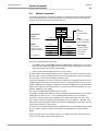
Block diagram: CLV functions .......................................................................................... 3-5
Optimization of the depth of field for the object....................................................... 3-6
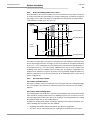
Dynamic focus control: classification of the reading range in
distance configurations ...................................................................................................... 3-7
LEDs .......................................................................................................................................... 3-8
Line scanner: replacing the laser warning labels ..................................................... 4-2
Line scanner: position of the securing threads on the CLV ................................. 4-3
Line scanner: Mounting possibilities of the CLV ....................................................... 4-3
Scanning methods: alignment with bar code and conveyor direction ............. 4-4
Definition of the reading distance a and of the aperture angle a...................... 4-4
Line scanner: Reading angle between the scan line and the bar code .......... 4-5
Avoiding surface reflections: Angle between the emitted light and
the bar code (tilted away from the vertical axis) ...................................................... 4-5
Count direction of the code position CP in the scan line and of the
code angle CW for the oscillating mirror...................................................................... 4-6
Line scanner: scan line in Adjusting mode ................................................................. 4-9
Line scanner: mounting example for the external reading pulse sensor......4-10
Mounting example for object distance detection ..................................................4-12
Block diagram: Connection of the CLV to the AMV/S 60
connection module .............................................................................................................. 5-3
Connecting the host interface .......................................................................................5-14
Connecting the terminal interface................................................................................5-15
Connections of the "Sensor" switching input ..........................................................5-16
Connections of the "IN 0 ... IN 4" switching inputs................................................5-17
Connections of the "Result 1 ... Result 4" switching outputs ............................5-20
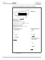
Bar code pattern (Code 39; module width 0.35 mm; Print ratio 2:1)............. 6-3
Narrowing the visible range using limit values.........................................................6-10
Oscillating mirror: "Oscillating with fixed amplitude" mode.................................6-13
Oscillating mirror: "Oscillating with variable amplitude" mode ..........................6-14
One-Shot: Object tracking (bar code read from front) .........................................6-15
CLV-Setup: Displaying the reading result in the Terminal Emulator................6-20
Reading result of the terminal interface: structure for Good Read .................6-21
Reading result of the terminal interface: structure for No Read ......................6-21
CLV-Setup: Displaying the percentage evaluation in the
Terminal Emulator ..............................................................................................................6-23
CLV-Setup: Dialog window for running the background teach-in .....................6-25
CLV-Setup: Display of th learned background ........................................................6-26
Appearance of scan line in the "Show CP-limits" mode......................................6-27
CLV-Setup: "Operating Data" dialog box ...................................................................6-28
CLV-Setup: Displaying the reading result of the host interface in
the Terminal Emulator with direction identifier at the beginning
(in this case: O = Output) ................................................................................................6-30
CLV-Setup: Displaying the self-test result in the Terminal Emulator...............6-31
CLV-Setup: Dialog box for executing Show limits...................................................6-32
Cleaning the reading window ........................................................................................... 7-1
Cleaning the external optical sensors (reading pulse generator,
object-height detector)....................................................................................................... 7-2
Dimensions of the CLV 490 line scanner, front reading window....................... 9-3
Dimensions of the CLV 490: line scanner with oscillating mirror,
side reading window............................................................................................................ 9-4
CLV 490-0010/-0011 (Standard density): Reading field height as
a function of the reading distance and resolution................................................10-3
CLV 490-0010/-0011 (Standard density): Min. and Max. reading
distance (measured radially) as a function of the focus position at a
resolution of 0.35 mm and an aperture angle of α = 40° ................................10-4
© SICK AG · Division Auto Ident · Germany · All rights reserved
8 008 796/0000/25-06-2002
Operating Instructions
Figures and tables
CLV 490 Bar Code Scanner
Fig. 10-3:
Fig. 10-4:
Fig. 10-5:
Fig. 10-6:
Fig. 10-7:
Fig. 10-8:
Fig. 10-9:
Fig. 10-10:
Fig. 10-11:
Fig. 10-12:
Fig. 10-13:
Fig. 10-14:
Fig. 10-15:
Fig. 10-16:
Fig. 10-17:
Fig. 10-18:
Fig. 10-19:
Fig. 10-20:
Fig. 10-21:
Fig. 10-22:
Fig. 10-23:
Fig. 10-24:
8 008 796/0000/25-06-2002
CLV 490-0010/-0011 (Standard density): Min. and Max. reading
distance (measured radially) as a function of the focus position at a
resolution of 0.35 mm and an aperture angle of α = 56° ................................ 10-5
CLV 490-0010/-0011 (Standard density): Min. and Max. reading
distance (measured radially) as a function of the focus position at a
resolution of 0.50 mm and an aperture angle of α = 40° ................................ 10-6
CLV 490-0010/-0011 (Standard density): Min. and Max. reading
distance (measured radially) as a function of the focus position at a
resolution of 0.50 mm and an aperture angle of α = 56° ................................ 10-7
Characteristics field CLV 490-0010/-0011: Scanning frequency as a
function of the reading distance and resolution .................................................... 10-8
CLV 490-1010/-1011 (Standard density): Reading field height as a
function of the reading distance and resolution .................................................... 10-9
CLV 490-1010/-1011 (Standard density): Min. and Max. reading
distance (measured radially) as a function of the focus position at a
resolution of 0.35 mm and an aperture angle of α = 40° ............................. 10-10
CLV 490-1010/-1011 (Standard density): Min. and Max. reading
distance (measured radially) as a function of the focus position at a
resolution of 0.35 mm and an aperture angle of α = 50° ............................. 10-11
CLV 490-1010/-1011 (Standard density): Min. and Max. reading
distance (measured radially) as a function of the focus position at a
resolution of 0.50 mm and an aperture angle of α = 40° ............................. 10-12
CLV 490-1010/-1011 (Standard density): Min. and Max. reading
distance (measured radially) as a function of the focus position at a
resolution of 0.50 mm and an aperture angle of α = 50° ............................. 10-13
Characteristics field CLV 490-1010/-1011: Scanning frequency as
a function of the reading distance and resolution.............................................. 10-14
CLV 490-1010/-1011 (Standard density): deflection range as a
function of reading distance, deflection angle and resolution ....................... 10-15
CLV 490-2010/-2011 (High density): Reading field height as a
function of the reading distance and resolution ................................................. 10-16
CLV 490-2010/-2011 (High density): Min. and Max. reading
distance (measured radially) as a function of the focus position at a
resolution of 0.25 mm and an aperture angle of α = 40° ............................. 10-17
CLV 490-2010/-2011 (High density): Min. and Max. reading
distance (measured radially) as a function of the focus position at a
resolution of 0.35 mm and an aperture angle of α = 40° ............................. 10-18
CLV 490-2010/-2011 (High density): Min. and Max. reading
distance (measured radially) as a function of the focus position at a
resolution of 0.35 mm and an aperture angle of α = 56° ............................. 10-19
Characteristics field CLV 490-2010/-2011: Scanning frequency as
a function of the reading distance and resolution.............................................. 10-20
CLV 490-3010/-3011 (High density): Reading field height as a
function of the reading distance and resolution ................................................. 10-21
CLV 490-3010/-3011: (High density) Min. and Max. reading
distance (measured radially) as a function of the focus position at a
resolution of 0.25 mm and an aperture angle of α = 40° ............................. 10-22
CLV 490-3010/-3011 (High density): Min. and Max. reading
distance (measured radially) as a function of the focus position at a
resolution of 0.35 mm and an aperture angle of α = 40° ............................. 10-23
CLV 490-3010/-3011 (High density): Min. and Max. reading
distance (measured radially) as a function of the focus position at a
resolution of 0.35 mm and an aperture angle of α = 50° ............................. 10-24
Characteristics field CLV 490-3010/-3011: Scanning frequency as
a function of the reading distance and resolution.............................................. 10-25
CLV 490-3010/-3011: Deflection range as a function of reading
distance, deflection angle and resolution.............................................................. 10-26
© SICK AG · Division Auto Ident · Germany · All rights reserved
I-13
Figures and tables
Operating Instructions
CLV 490 Bar Code Scanner
Fig. 10-25: CLV 490-6010/-6011 (Low density): Reading field height as a
function of the reading distance and the tilt at a resolution of 0.5 mm.....10-27
Fig. 10-26: CLV 490-6010/-6011 (Low density): Min. and Max. reading
distance (measured radially) as a function of the focus position at a
resolution of 0.5 mm and an aperture angle of α = 40° ................................10-28
Fig. 10-27: CLV 490-6010/-6011 (Low density): Min. and Max. reading
distance (measured radially) as a function of the focus position at a
resolution of 0.5 mm and an aperture angle of α = 60° ................................10-29
Fig. 10-28: Characteristics field CLV 490-6010/-6011: Scanning frequency as
a function of the reading distance and resolution ..............................................10-30
Fig. 10-29: CLV 490-7010/-7011 (Low density): Reading field height as a
function of the reading distance and tilt at a resolution of 0.5 mm.............10-31
Fig. 10-30: Characteristics field CLV 490-7010/-7011: Scanning frequency
as a function of the reading distance and resolution ........................................10-32
Fig. 10-31: CLV 490-7010/-7011: Deflection range as a function of reading
distance, deflection angle and tilt at a resolution of 0.5 mm .........................10-33
Fig. 10-32: External parameter memory, installed on the CLV .............................................10-34
Fig. 10-33: CLV-Setup: "Device configuration" tab with the CLV start options ..............10-35
Fig. 10-34: CLV-Setup: dialog box for adjusting the external parameter memory........10-36
Fig. 10-35: CLV with heater: temperature curve inside the housing ..................................10-38
Fig. 10-36: CLV-Setup: Result display of the AutoBaud Detect function ..........................10-44
Fig. 10-37: User interface of the "CLV-Setup" software .........................................................10-45
Fig. 10-38: CLV-Setup: entering commands in the Terminal Emulator .............................10-49
Fig. 10-39: Line scanner: calculating the number of scans for ladder-type bar
code arrangements ........................................................................................................10-51
Fig. 10-40: Line scanner: calculating the number of scans for fence-type bar
code arrangements ........................................................................................................10-51
Fig. 10-41: Line scanner with oscillating mirror: calculating the number of scans
for fence-type bar code positioning .........................................................................10-52
Fig. 10-42: One-Shot: Line scanner with oscillating mirror: calculating the number
of scans for fence-type bar code positioning .......................................................10-53
Fig. 10-43: Required distance between the bar codes on an object.................................10-54
Fig. 10-44: Parameterization example: prepare a sketch of the reading situation.......10-57
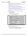
Fig. 10-45: Parameterization example: settings on the "Reading Configuration" tab..10-58
Fig. 10-46: Parameterization example: "Edit Auto Focus/Adjustments"
dialog window....................................................................................................................10-59
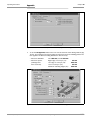
Fig. 10-47: Parameterization example: "Edit Auto Focus/Limits" dialog window ..........10-59
Fig. 10-48: Parameterization example: "Edit Auto Focus/Optimizations"
dialog window....................................................................................................................10-60
Fig. 10-49: Parameterization example: Buttons on the "Device Configuration" tab ....10-60
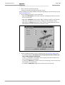
Fig. 10-50: Parameterization example: "Edit Scanner Position/Angles"
dialog window....................................................................................................................10-61
Fig. 10-51: Parameterization example: "Edit Scanner Position/Coordinates"
dialog window....................................................................................................................10-62
Fig. 10-52: Parameterization example: Settings on the "Device Configuration" tab....10-62
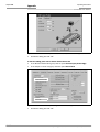
Fig. 10-53: Parameterization example: settings on the "Code Configuration" tab .......10-63
Fig. 10-54: Parameterization example: "2/5 Interleaved" tab..............................................10-63
Fig. 10-55: Parameterization example: "Host interface" tab (base setting)....................10-64
Fig. 10-56: Parameterization example: "Data Strings" tab (basic setting).......................10-64
Fig. 10-57: Auxiliary input via the terminal interface of the CLV ...........................................10-65
Fig. 10-58: CLV-Setup: auxiliary input on the Terminal Emulator.........................................10-66
Fig. 10-59: Dimensions of the angle bracket, single No. 2 013 824 ................................10-75
Fig. 10-60: Dimensions of the articulated bracket No. 2 018 435....................................10-75
Fig. 10-61: Front view of quick clamping device No. 2 016 110 with angle
braket No. 2 0130824 .................................................................................................10-75
Fig. 10-62: Reproduction of the declaration of conformity (Page 1, reduced in size) .10-85
Fig. 10-63: Reproduction of the declaration of conformity (Page 2, reduced in size) .10-86
Fig. 10-64: Scannable bar codes with various module widths (print ratio 2:1) .............10-91
I-14
© SICK AG · Division Auto Ident · Germany · All rights reserved
8 008 796/0000/25-06-2002
Operating Instructions
Notes on this document
Chapter 1
CLV 490 Bar Code Scanner
1
Notes on this document
1.1
Purpose
This document is a guide to the operation of the barcode scanner
•
CLV 490 with auto-focus
in the following variations:
•
Line scanner
– CLV 490-2010, resolution from 0.20 mm (high density)
– CLV 490-2011, resolution from 0.20 mm (high density), with heater
– CLV 490-0010, resolution from 0.30 mm (standard density)
– CLV 490-0011, resolution from 0.30 mm (standard density), with heater
– CLV 490-6010, resolution from 0.40 mm (low density)
– CLV 490-6011, resolution from 0.40 mm (low density), with heater
•
Line scanner with oscillating mirror
– CLV 490-3010, resolution from 0.20 mm (high density)
– CLV 490-3011, resolution from 0.20 mm (high density), with heater
– CLV 490-1010, resolution from 0.30 mm (standard density)
– CLV 490-1011, resolution from 0.30 mm (standard density), with heater
– CLV 490-7010, resolution from 0.40 mm (low density)
– CLV 490-7011, resolution from 0.40 mm (low density), with heater
This document provides information on
•
Mounting and connecting the device
•
Startup
•
Operating and configuring (parametrizing) the device
•
Maintenance
•
Exchanging the device without losing the parameter set
•
Special applications and procedures
The bar code scanner with all its variants will in this manual be referred to as the "CLV",
except where a distinction is necessary.
1.2
Target audience
This document is intended for persons who are responsible for the following activities:
1.2.1
Mounting, electrical installation, maintenance and replacement
Electricians and service technicians.
1.2.2
Startup, operation and configuration
Technicians and engineers.
8 008 796/0000/25-06-2002
© SICK AG · Division Auto Ident · Germany · All rights reserved
1-1
Notes on this document
Chapter 1
Operating Instructions
CLV 490 Bar Code Scanner
1.3
Information content
This document contains all the information required to mount, install, and start up the CLV
with the factory settings.
A series of step-by-step instructions is provided for each of these activities.
Configuration of the CLV for the application-specific reading situations is carried out with
the Windows-oriented PC software "CLV-Setup". Further assistance is also available in the
form of the online help system CLV-Setup Help. The procedure for installing and operating
the software is described in the appendix.
For further information on the design of the bar code scanner or on bar code technology in
general, please contact the Division Auto Ident at SICK AG.
1.4
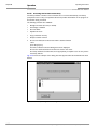
Symbols
Some of the information in this document is marked specially so that you can access it
quickly:
Warning!
Warnings are provided to prevent injury to operating personal or serious damage to the bar
code scanners.
¾
Note
Explanation
Recommendation
Tip
Default
SCANNING FREQUENCY
Always read warnings carefully and observe them at all times.
Indicates special features or characteristics.
Explanations provide background information on technical features.
Recommendations help you carry out certain procedures more effectively.
Tips explain settings in the user interface of the "CLV-Setup" program.
Marks a section containing the factory defaults.
This typeface is used to refer to a term in the "CLV-Setup" program.
Icons refer to buttons in the "CLV-Setup" program.
"Host receive fault"
This typeface is used for messages output via the terminal interface of the CLV.
This symbol is used to mark sections that describe steps carried out with the "CLV-Setup"
program.
This symbol refers to additional technical documentation.
¾
Ö
1-2
Here you have to do something. This symbol characterizes single-step operating
instructions. Multiple-step operating instructions are characterized by sequential numbers.
Here you select a function of the "CLV-Setup" user interface.
© SICK AG · Division Auto Ident · Germany · All rights reserved
8 008 796/0000/25-06-2002
Operating Instructions
Safety information
Chapter 2
CLV 490 Bar Code Scanner
2
Safety information
2.1
Authorized users
For the CLV to function correctly and safely, it must be mounted and operated by sufficiently
qualified personnel.
The following qualifications are required for the various tasks involved:
2.1.1
Mounting and maintenance
•
General technical training
•
Knowledge of the standard guidelines relating to safety at the workplace
2.1.2
Electrical installation and replacement
•
Practical training in electrical engineering
•
Knowledge of the standard safety guidelines relating to electrical engineering
•
Experience operating the devices in the relevant application (e. g. conveyor belt)
2.1.3
Startup, operation and configuration
•
Experience operating the devices in the relevant application (e. g. conveyor belt)
•
Knowledge of the hardware and software environment of the relevant application
(e. g. conveyor belt)
•
Basic understanding of Windows 95TM/98TM, Windows NTTM or Windows XPTM
•
Ability to use an HTML browser (e. g. Netscape NavigatorTM)
•
Basic understanding of data transfer methods
•
Basic understanding of bar code technology
2.2
Intended use
The CLV is designed to detect and decode bar codes automatically. It is mounted in a
reading station and reads bar codes on objects positioned on a conveyor belt, for example.
The CLV transfers the data content of the decoded bar codes via its host interface to a host
for further processing.
Any warranty claims vis-à-vis SICK AG will be rendered invalid if the device is used for any
other purpose or if changes are made to the device, also as part of the mounting and
electrical installation procedures.
2.3
¾
8 008 796/0000/25-06-2002
General safety instructions and protection measures
Always read the general safety instructions carefully and observe them at all times.
Please also observe the warnings in front of the operating instructions in each chapter
of this document.
© SICK AG · Division Auto Ident · Germany · All rights reserved
2-1
Chapter 2
Safety information
Operating Instructions
CLV 490 Bar Code Scanner
Shock hazard!
Depending on the type of device, the AMS 60 Connection Module (accessory) for the CLV
is connected to a mains voltage of 230 V AC 50 Hz or 115 V AC 50/60 Hz.
¾
When working with electrical equipment, always follow the relevant safety specifications.
Laser beam can cause blindness!
The CLV uses a class 2 red-light laser. Looking directly at the laser beam can seriously
damage your eyesight.
¾
¾
¾
¾
¾
Never look directly into the path of the beam (similar to sunlight).
Do not direct the laser beam at other persons.
When mounting and aligning the CLV, avoid reflections caused by reflective surfaces.
Do not open the housing.
(Opening the housing does not deactivate the laser diode.)
Observe the most recent laser specifications (DIN EN 60825-1, latest version).
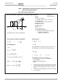
Laser power
The laser operates at a wave length of λ = 650 nm (visible red light). The power output at
the reading window is max. 2.8 mW.
The emitted radiation is not dangerous to human skin.
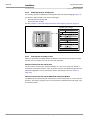
Laser warnings
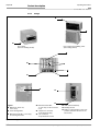
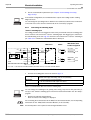
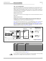
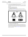
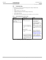
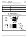
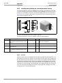
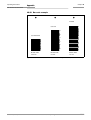
The laser warning symbols applicable for Europe (Fig. 2-1) can be found on the CLV at the
following locations:
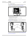
•
The laser warning symbol on line scanners is positioned beside the reading window on
the front side of the device. The GB/US laser warning is located on the side containing
the electrical connections (see Fig. 3-1, Page 3-4.)
•
The laser warning symbol on line scanners with oscillating mirror is located above the
reading window, on the cover of the mirror. The GB/US laser warning is located on the
side containing the electrical connections.
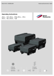
mW
2,8
Max. output radiation:
s
111
Pulse duration:
nm
650
Emitted wavelength:
EN 60825-1: 1994 + A11 : 1996
CLASS II LASER PRODUCT
Max. Output:
mW
2,8
Pulse duration:
us
56
Wavelength:
nm
650
Compiles with 21 CFR 1040.10
Fig. 2-1:
2-2
Laser warning labels on the CLV (applicable for Europe)
© SICK AG · Division Auto Ident · Germany · All rights reserved
8 008 796/0000/25-06-2002
Safety information
Operating Instructions
Chapter 2
CLV 490 Bar Code Scanner
Note
A set of laser warnings in German/US English and French/US English is included in the
delivery scope. The GB English/US English warnings can be pasted over with these if
necessary.
If the CLV is installed in a machine/panel with the result that the laser warning labels
are no longer visible, additional warnings (not included in the scope of delivery) must
be provided on the machine beside the emergence aperture of the laser beam.
Internal protective circuits
The CLV is equipped with monitoring circuits that deactivate the laser diode in the event of
a malfunction.
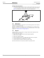
Activation and deactivation of the laser diode is controlled by the reading pulse trigger.
A timer (laser timeout) automatically deactivates the laser diode in Reading mode ("Sensor
input" and "Serial interface" trigger mode) if the reading interval has not ended after
10 minutes (default setting). However, it does not end the reading interval. In this case, the
CLV outputs the message:
"Laser safety timeout"
on the terminal interface. The reading interval must be terminated by resetting the trigger
signal. The laser diode is activated again by the next reading trigger.
In the Percentage Evaluation mode, Adjusting mode and Show CP-limits as well as in
the Free-running Reading mode the laser diode is constantly activated.
Note
In the Reading mode, the CLV carries out a distance measurement referencing at regular
intervals. During referencing, it turns the laser diode on for a maximum of 10 seconds.
2.4
Quick stop and quick restart
2.4.1
Stopping the CLV
¾
Switch off the power supply.
This can result in loss of the following (at the most):
•
The application-specific parameter set, if it was stored temporarily in the CLV
•
The last reading result
•
Daily operating data
(operating hours counter, number of reading intervals, Good Read count, maximum
duration trigger, minimum duration trigger, average identification quality)
2.4.2
¾
8 008 796/0000/25-06-2002
Restarting the CLV
Switch on the power supply.
The CLV resumes operation with the parameter set that was last stored permanently
and reset the daily operating data.
© SICK AG · Division Auto Ident · Germany · All rights reserved
2-3
Chapter 2
Safety information
Operating Instructions
CLV 490 Bar Code Scanner
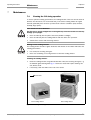
2.5
Environmental information
The CLV is designed to cause minimum impact on the environment. It does not contain any
silicone-based materials and, therefore, does not represent any problems for paint sprayers
in paint shops, for example.
2.5.1
Power requirements
The power requirements depend on the variants:
•
The line scanner has a typical power consumption of 9 W and max. 16 W
•
The line scanner with oscillating mirror has a typical power consumption of 9 W and
max. 18 W
•
The line scanner equipped with an integrated heater has a typical power consumption
of 75 W and max. 90 W
•
The line scanner with oscillating mirror equipped with an integrated heater has a typical
power consumption of 75 W and max. 100 W
The values are given for devices with disconnected switching outputs.
2.5.2
Disposal after removal from service
Always dispose irreparable devices in a manner that is not harmful to the environment and
in accordance with the applicable national waste disposal regulations. The CLV can be separated into recyclable secondary raw materials and special-category waste (electronic
scrap).
See also Chapter 7.3 Disposal, Page 7-2.
SICK AG currently does not accept delivery of unusable or irreparable devices.
2-4
© SICK AG · Division Auto Ident · Germany · All rights reserved
8 008 796/0000/25-06-2002
Product description
Operating Instructions
Chapter 3
CLV 490 Bar Code Scanner
3
Product description
3.1
Design
3.1.1
Scope of delivery
The CLV is supplied with the following in the packing:
•
An information sheet (notes on device) with terminal diagram and Quick Start instructions
•
An additional set of Class 2 laser warning labels (self-adhesive) in German/US English
and French/US English
Depending on the number of devices ordered, one or more sets of technical documentation comprising:
•
These CLV 490 Operating Instructions in English and German
•
A CD-ROM containing the "CLV-Setup" program for WindowsTM, the CLV-Setup Help online help system, and the I-ViewProTM HTML browser
Chapter 10.13 Accessories, Page 10-71 contains an overview of the available accessories,
connection modules, cables, and connectors, as well as sensors for generating the reading
pulse.
3.1.2
Variants
Low density
Standard
High density
The CLV is currently available in the following variants:
Type (red light)
Part. no.
Scanning method
Resolution
Reading window
Heater
CLV 490-2010
1 019 311
Line scanner
From 0.2 mm
End
No
CLV 490-3010
1 019 313
Line scanner with oscillating mirror
From 0.2 mm
Side
No
CLV 490-2011
1 019 312
Line scanner
From 0.2 mm
End
Yes
CLV 490-3011
1 019 314
Line scanner with oscillating mirror
From 0.2 mm
Side
Yes
CLV 490-0010
1 016 958
Line scanner
From 0.3 mm
End
No
CLV 490-1010
1 016 959
Line scanner with oscillating mirror
From 0.3 mm
Side
Yo
CLV 490-0011
1 016 960
Line scanner
From 0,3 mm
End
Yes
CLV 490-1011
1 016 961
Line scanner with oscillating mirror
From 0.3 mm
Side
Yes
CLV 490-6010
1 018 872
Line scanner
From 0.4 mm
End
No
CLV 490-7010
1 019 094
Line scanner with oscillating mirror
From 0.4 mm
Side
No
CLV 490-6011
1 019 095
Line scanner
From 0.4 mm
End
Yes
CLV 490-7011
1 019 096
Line scanner with oscillating mirror
From 0.4 mm
Side
Yes
Table 3-1: CLV variants
8 008 796/0000/25-06-2002
© SICK AG · Division Auto Ident · Germany · All rights reserved
3-1
Chapter 3
Product description
Operating Instructions
CLV 490 Bar Code Scanner
3.1.3
CLV without heater
System requirements
The following are required to start up and operate the CLV without heater:
1.
A SICK Connection Module to provide the power supply and connect the data and
function interfaces.
Available types:
– For connecting one CLV:
AMV 60-011 (no. 1 017 134) for 18 ... 30 V DC, enclosure rating max. IP 54
AMS 60-013 (no. 1 017 139) for 230 V AC 50 Hz/24 V DC,
enclosure rating max. IP 54
AMS 60-012 (no. 1 017 140) for 115 V AC 50/60 Hz/24 V DC,
enclosure rating max. IP 54
AMS 100-011 (no. 6 021 105) for 18 ... 30 V DC, enclosure rating max. IP 65
– For connecting two CLVs:
AMV 30-071 (no. 1 017 391) for 18 ... 30 V DC, enclosure rating max. IP 54
AMV 200-011 (no. 6 021 106) for 18 ... 30 V DC, enclosure rating max. IP 65
– or –
Alternatively, a non-SICK Power pack with a voltage output of 18 ... 30 V DC pursuant
to IEC 742 (functional extra-low voltage) and a minimum power output of 20 W.
Cable no. 2 020 264 (3 m) with 15-pin D Sub HD connector and one open end for
connecting the CLV to the non-SICK Power pack (supply voltage).
2.
The following operating voltages/power output values:
– AMV 60-011: 18 ... 30 V DC (to IEC 742), min. 20 W
– AMV 30-071: 18 ... 30 V DC (to IEC 742), min. 40 W
– AMV 100-011: 18 ... 30 V DC (to IEC 742), min. 20 W
– AMV 200-011: 18 ... 30 V DC (to IEC 742), min. 40 W
– AMS 60-013: 230 V AC ±10 % 50 Hz
– AMS 60-012: 115 V AC ±10 % 50/60 Hz
3.
Fitting cables see Chapter 5.2.2 Prefabricated cables (overview), Page 5-2.
4.
With external clock pulse supply via the "Sensor" switching input: a suitable reading pulse sensor for signaling an object with a bar code, e.g. a photoelectric reflex switch.
5.
With object distance detection via the "IN 0 ... IN 4" switching inputs: suitable sensors
for multi-stage dynamic focus control, e. g. photoelectric reflex switches.
6.
A PC (min. 80486, 66 MHz, 16 MB RAM, CD drive, a serial port (COM x), mouse (recommended)) with Windows 95TM/98TM, Windows NTTM or Windows XPTM.
7.
An RS 232 data connection cable with two 9-pin D Sub sockets for connecting the PC
to the terminal interface of the CLV in the Connection Module, e. g. no. 2 014 054.
Pin 2 (RxD) and Pin 3 (TxD) are crossed.
8.
An HTML browser, e. g. Netscape NavigatorTM, or the I-ViewProTM browser supplied with
the device (see Chapter 3.1.1 Scope of delivery, Page 3-1) for using the online help system CLV-Setup Help.
9.
The appropriate bus connection module BMV/BMH 10 (available on request) for connecting the CLV to the Interbus-S, Profibus DP, the Device Net or to Ethernet.
10. For connection of the CLV to the CAN Scanner Network: the Operating Instructions
“Application of the CAN interface“ (no. 8 009 180, English edition).
3-2
© SICK AG · Division Auto Ident · Germany · All rights reserved
8 008 796/0000/25-06-2002
Operating Instructions
Product description
Chapter 3
CLV 490 Bar Code Scanner
CLV with heater
The following are required to start up and operate the CLV with heater:
1.
A SICK Connection Module from the AMV 100 or AMV 200 series to provide the power
supply and connect the data and function interfaces.
Available types:
– For connecting one CLV: AMV 100-011 (no. 6 021 105) for 24 V DC, max. IP 65
– For connecting two CLVs: AMV 200-011 (no. 6 021 106) for 24 V DC, max. IP 65
– or –
Alternatively, a non-SICK Power pack with a voltage output of 24 V DC +20 %/–10 %
to IEC 742 (functional extra-low voltage) and a minimum power output of 100 W.
Cable no. 2 020 264 (3 m) with 15-pin D Sub HD connector and one open end for
connecting the CLV to the non-SICK Power pack (supply voltage).
2.
The following operating voltages/power output values:
– AMV 100-011: 24 V DC +20 %/–10 % (pursuant to IEC 742), min. 100 W
– AMV 200-011: 24 V DC +20 %/–10 % (pursuant to IEC 742), min. 200 W
3.
8 008 796/0000/25-06-2002
See pos. 3 under CLV without heater
© SICK AG · Division Auto Ident · Germany · All rights reserved
3-3
Product description
Chapter 3
Operating Instructions
CLV 490 Bar Code Scanner
3.1.4
Design
➋
➋
➋
Line scanner
(front-end reading window)
Line scanner with oscillating mirror
(side reading window)
➋
➊
➌
➍
➎
➏
➐
➑
➒
➍ Blind hole thread M 4,
Legend
➊ Drilled hole, Ø 3.6 mm,
6 mm deep
➋ Laser warning labels
➌ Blind hole thread M 6, 7 mm deep,
for securing the device
Fig. 3-1:
3-4
10 mm deep, for the connector
cover
➎ "Host/Term" connector
15-pin D Sub HD plug
➏ "I/O" connector,
15-pin D Sub HD socket
➐ LEDs (status indicators)
➑ Reading window
➒ Mark for count direction of the code
position (deflection direction of the
laser beam)
Design of the CLV 490
© SICK AG · Division Auto Ident · Germany · All rights reserved
8 008 796/0000/25-06-2002
Operating Instructions
Product description
Chapter 3
CLV 490 Bar Code Scanner
3.2
Method of operation
The CLV first scans the bar code with a scan line and then decodes it. The data is forwarded
via the main data interface (serial host interface) to a host/PC for further processing. An
overview of the CLV functions is provided in Fig. 3-2.
CLV 490
Scanner
PC
Operation
Parameterization,
etc.
Decoder
Photoelectric
switch
Reading pulse
Signal1)
Focal control
Trigger One-Shot
Conveyer increment
Interface
"Terminal"
"Sensor"
"Host"
HOST
Further processing
of the reading result
"IN 1"
"Result 1"
Status display
e. g. Device Ready
"IN 2"
"Result 2"
e. g. Good Read
"IN 3"
"Result 3"
e. g. No Read
"IN 4"
"Result 4"
e. g. Match 1
"IN 0"
1) if required
VS
Fig. 3-2:
Block diagram: CLV functions
The CLV is equipped with two decoders:
•
The SMART decoder (SICK Modular Advanced Recognition Technology) for decoding
bar codes with small code height, bar codes that are dirty or damaged, as well as bar
codes that are tilted excessively (azimuth angle)
•
The tried-and-tested standard decoder of the CLV series
The CLV derives useful diagnosis data from the reading process and can transfer it to also
the host. It also records operating data that can be interrogated at any time. The quality of
the read can be checked in percentage evaluation mode.
To start the reading process when an object is located in the reading field, the CLV requires
a suitable trigger. This opens an internal time window ("reading interval") in the CLV. In the
default configuration, this trigger is supplied by an external reading pulse sensor. Alternative
trigger sources include Free-running mode or a command via the host interface (for more
complex applications: OTC trigger).
The current operating status is indicated by four LEDs.
If the trigger is supplied externally, the "Sensor" switching input instructs the CLV to start the
reading process. The five "IN 0 ... IN 4" switching inputs switch the focus position in
response to certain events, as an alternative to the autofocus function. The "IN 3" and
"IN 4” inputs can also be assigned special functions. The four "Result 1 ... Result 4" switching outputs can be assigned to different functions for displaying the result status and also
control external devices, such as a PLC.
The CLV is operated and configured via the auxiliary interface (serial terminal interface) using
the "CLV-Setup" software or via the host interface/terminal interface using command
strings.
System, warning, and error messages help you to configure the device and to locate the
source of errors during startup and reading mode.
8 008 796/0000/25-06-2002
© SICK AG · Division Auto Ident · Germany · All rights reserved
3-5
Chapter 3
Product description
Operating Instructions
CLV 490 Bar Code Scanner
3.2.1
Autofocus function
The autofocus function enables the CLV to detect the distance of an object during the reading process, without the need for external sensors, and then adjusts the focus position automatically to the reading plane of the bar code. In order to do so, the CLV measures the
object distance each time in its reading field in front of the reading window and internally
creates a distance profile. Following this, it positions the focus on the object.
3 operating modes are provided for various applications:
•
Minimum distance: the CLV focuses on the minimum distance in the distance profile
and ignores the background in the reading field. Application: with unobstructed view of
the object without any surrounding objects protruding into the reading plane. One object
with bar code(s) only is inside the reading field during one reading pulse.
•
Differential background: the distance profile of the reading field background is programmed (teach-in) in the CLV without any objects present. During the reading process,
the CLV then focuses on the object which it recognizes by comparing it to the distance
profile of the background. Application: with unobstructed view of the object restricted
by other objects that protrude into the reading plane. One object with barcode(s) only
is inside the reading field during one reading pulse.
•
Differential background and tracking: if several objects with different distances are
positioned in the reading field at the same time (distance conflict), the CLV focuses on
the object that is nearest to but has not exceed its internal focus switchover point.
Application: in OTS operation (applications with tracking by the Omni Tracking Controller
OTC 400).
The distance profile of the background can also be displayed in the "CLV-Setup" program.
The reading field is defined by the autofocus range, the aperture angle, and (in the case of
line scanners with oscillating mirror) also by the angle of deflection. The park setting of the
focus position, from which the device focuses for each read, can be specified in addition to
a time and/or position-related delay (timeout or hysteresis). If necessary, an offset can be
defined for the focus position to be set by the measurement. The depth of field, which radiates in the direction of the scan lines and is caused by the V-principle of the beam deflection, is optimized as a result (Fig. 3-3).
Measured distance
Optimum focus position:
measured distance plus offset for maximum
Depth of field (DOF)
Fig. 3-3:
3-6
Optimization of the depth of field for the object
© SICK AG · Division Auto Ident · Germany · All rights reserved
8 008 796/0000/25-06-2002
Operating Instructions
Product description
Chapter 3
CLV 490 Bar Code Scanner
3.2.2
Event-controlled dynamic focus control
As an alternative to the autofocus function, the CLV can switch its focus position in response
to certain events and thus dynamically cover a large reading range. A maximum of eight reading ranges can be defined as distance configurations for this purpose and approached
consecutively in reading mode (see Fig. 3-4).
Reading
field height
1
2
3
4
5
6
7
8
Focus position
Reading distance
DC 8
DC 6
Focus
position
DC 7
DC 5
DC 4
DC 3
DC 2
DC 1
Reading distance
DC = Distance Configuration
Fig. 3-4:
Dynamic focus control: classification of the reading range in distance configurations
The switch over takes place in response to changes in the object distance (with reads from
above: object height detection). The trigger source for the switchover is a signal combination
at the "IN 0 ... IN 4" switching inputs, a command on the host interface/terminal interface or
the integrated timer (e. g. for search mode). Additional in the case of the line scanner with
oscillating mirror also the oscillating mirror reversal points. The distance configurations are
assigned to the switchover sequence by means of a programmable assignment table. The
distance measurement of the autofocus function can be additionally used to define the distance configurations.
3.2.3
Scan procedure variants
Line scanner (standard device)
Generates a scan line; due to the V-principle of the beam generation, the reading field height
(the useful length of the scan line for evaluation purposes) is dependent on the reading
distance.
Line scanner with oscillating mirror
The oscillating mirror also deflects the scan line perpendicularly to the scan direction at both
sides around the neutral position with a low oscillating frequency. As a result, the CLV can
also scan larger areas for bar codes. Due to the V-principle of beam generation, the reading
field height is dependent on the reading distance.
In addition to parking (fixed position) and simple deflection with maximum amplitude, optimized oscillating mirror functions are also available:
8 008 796/0000/25-06-2002
•
Oscillating with variable deflection amplitude per distance configuration
•
One-Shot: one-off, defined deflection per reading pulse (forward and return phase)
© SICK AG · Division Auto Ident · Germany · All rights reserved
3-7
Chapter 3
Product description
Operating Instructions
CLV 490 Bar Code Scanner
3.2.4
Additional components
Heater
The CLV can be permanently equipped with a heater for applications involving temperatures
up to max. –35 °C (e. g. in a freezer).
The design, technical data, and power-up behavior of the CLV are described in Chapter 10.4
Optional heating, Page 10-38.
External parameter memory
The external parameter memory is located in a connector cover which, when mounted,
covers the two electrical terminals on the CLV (IP 65). The parameter memory saves you
time when a CLV is replaced locally by providing a copy of the current parameter set. In other
words, you do not have to configure the new device.
For information on applications and operating procedures, see Chapter 10.3 Installing and
operating the external parameter memory, Page 10-34.
3.3
Indicators and control elements
3.3.1
Control elements
The CLV is operated and configured via the terminal interface (auxiliary interface) using the
"CLV-Setup" program or using command strings sent via the host interface/terminal interface. A variety of parameter options allow you to adapt the device to a wide range of applications.
The following can be defined:
•
The configuration of the code types
•
The read, evaluation, and output properties
•
The communication parameters of the host interface
•
The structure of the data output string for "Good Read" and "No Read" on the host interface
•
The function of the terminal interface
Chapter 10.6 Installing and operating the "CLV-Setup" program, Page 10-41 describes the
procedure for installing the "CLV-Setup" program and explains how to use it. The parameterization (configuration) procedure is explained in Chapter 6.4 Configuring (parameterization)
the CLV, Page 6-5.
3.3.2
Function of the LEDs
Four LEDs indicate the operating status, activity of the laser diode, reading result status, and
data transfer on the host interface. The LEDs are located on the rear of the device (Fig. 3-5).
If the optional external parameter memory is connected, the LEDs also indicate whether the
memory was successfully accessed.
Device Ready
Sensor
Read Result
Data
Fig. 3-5:
3-8
LEDs
© SICK AG · Division Auto Ident · Germany · All rights reserved
8 008 796/0000/25-06-2002
Operating Instructions
Product description
Chapter 3
CLV 490 Bar Code Scanner
The meaning of the LEDs in the various operating modes/functions is shown in Table 3-2
and Table 3-3.
CLV without external parameter memory
Operating mode LED
Start
Display
Device Ready Green
Function
• Lights up after power-up if the self-test was successful
Subsequent behavior depends on selected start option
Start option: START WITH EXTERNAL PARAMETERS (DEFAULT)
• Lights up constantly (CLV has loaded internal parameter set)
Start option: START WITH INTERNAL PARAMETERS:
• Lights up constantly (CLV has loaded internal parameter set)
Start option: START WITH COPY INTERN -> EXTERN:
• Blinks constantly together with the "Read Result" LED1)
(CLV has loaded internal parameter set)
Read Result
Green
Start option: START WITH COPY INTERN -> EXTERN:
• Blinks constantly together with the "Device Ready" LED1)
Device Ready Green
• Lights up constantly
• Extinguishes with new operating mode/function
Sensor
Green
• Lights up if reading diode is active
(The laser diode is activated/deactivated by reading pulse)
• Lights up constantly in Free-running mode, since laser diode is always active
Read Result
Green
LED is linked to the "Result 2" switching output and indicates the selected result
status for the defined pulse duration of the output.
• Lights up after a successful read (default: Good Read)
• Lights up if the match code comparison is active, the bar code read matches the
specified match code(s) and the corresponding result status output is selected
for the "Result 2" output
Data
Yellow
• Flickers when the CLV transfers data to the host on the host interface
Percentage
Sensor
Green
• Lights up constantly, as Free-running mode is active
evaluation
Read Result
Green
Behavior depends on the reading quality:
• Extinguishes if reading rate < 30 %
• Blinks twice a second if reading rate 30 % ... 70 %
• Blinks five times a second if reading rate 70 % ... 90 %
• Lights up constantly if reading rate > 90 %
Adjusting mode Sensor
Green
• Lights up constantly, as Free-running mode is active
Show CP-limits
Green
• Blinks bright/dark alternately, in the frequency with which the scan line is (partially)
masked out
Reading mode
Sensor
1) Set the start option to START WITH THE INTERNAL PARAMETERS on the DEVICE CONFIGURATION tab in the "CLV-Setup" program. Download to CLV!
Table 3-2: Meaning of LEDs: CLV without external parameter memory
8 008 796/0000/25-06-2002
© SICK AG · Division Auto Ident · Germany · All rights reserved
3-9
Product description
Chapter 3
Operating Instructions
CLV 490 Bar Code Scanner
CLV with external parameter memory connected
Operating mode LED
Display
Function
Start
Green
• Lights up after power-up if the self-test was successful
Device Ready
Subsequent behavior depends on selected start option:
Start option: START WITH EXTERNAL PARAMETERS (default):
• Blinks for approx. 10 s before lighting up constantly
(CLV has loaded the parameter set from the external parameter
memory and starts reading mode straight away)
• Blinks for approx. 10 s together with the "Read Result" LED, then lights up
constantly.
(CLV has loaded the parameter set from the external parameter memory with
tolerated errors1) and starts reading mode straight away)
• Lights up constantly
(CLV could not find an external parameter memory and loads the internal parameter set instead)
• Blinks constantly together with the "Read Result" LED2)
(The external parameter memory is either empty, contains the parameter set for
a different CLV type, or is corrupt.
CLV has loaded the internal parameter set. It starts Reading mode but does not
output data over the host interface.)
Start option: START WITH INTERNAL PARAMETERS:
• Lights up constantly (CLV has loaded internal parameter set)
Start option: START WITH COPY INTERN -> EXTERN:
• Blinks alternately with the "Read Result" LED for approx. 10 s before lighting
up constantly
(CLV has successfully copied the internal parameter set to the external memory
and has reset the start option to START WITH EXTERNAL PARAMETERS).
CLV has loaded the internal parameter set.
• Blinks constantly together with the "Read Result" LED2)
(The external parameter memory is either not connected or corrupt, or the
parameter set is too large to be copied). CLV has loaded the internal parameter
set.
Read Result
Green
Start option: START WITH EXTERNAL PARAMETERS (default):
• Blinks for approx. 10 s together with "Device Ready" LED 1) (see above) or
• Blinks constantly together with the "Device Ready" LED 2) (see above)
Start option: START WITH COPY INTERN -> EXTERN:
• Blinks alternately with "Device Ready" LED for approx. 10 s (see above) or
• Blinks constantly together with the "Device Ready" LED 2) (see above)
Reading mode
Device Ready
Green
• Lights up constantly
• Extinguishes with new operating mode/function
Sensor
Green
• Lights up if reading diode active
(The laser diode is activated/deactivated by the reading pulse)
• Lights up constantly in Free-running mode, since the laser diode is constantly
active
Read Result
Green
LED is linked to the "Result 2" output and indicates the selected result status for the
defined pulse duration of the output.
• Lights up after a successful read (Good Read)
• Lights up if the match code comparison is active, the bar code read matches the
specified match code(s) and the corresponding result output is selected for the
"Result 2" output
1) We recommend that you check the parameter set manually, e. g. by printing out the entire configuration. For troubleshooting, see also Chapter 8.3.2 LED error messages
for the external parameter memory, Page 8-5
2) Stops blinking when you switch from Reading mode to Parameterization mode
Table 3-3: Meaning of LEDs: CLV with external parameter memory
3-10
© SICK AG · Division Auto Ident · Germany · All rights reserved
8 008 796/0000/25-06-2002
Operating Instructions
Product description
Chapter 3
CLV 490 Bar Code Scanner
Operating mode LED
Display
Function
Reading mode
Data
Yellow
• Flickers when the CLV transmits data to the host over the host interface
Percentage
Sensor
Green
• Lights up constantly, since Free-running mode is active
evaluation
Read Result
Green
Behavior dependent on the reading quality:
• Extinguishes if reading rate < 30 %
• Blinks twice a second if reading rate 30 % ... 70 %
• Blinks five times a second if reading rate 70 % ... 90 %
• Lights up constantly if reading rate > 90 %
Adjusting mode Sensor
Green
• Lights up constantly, since Free-running mode is active
Show CP-limits
Green
• Blinks bright/dark alternately, in the frequency with which the scan line is (partially)
masked out
(contd.)
Sensor
Table 3-3: Meaning of LEDs: CLV with external parameter memory
8 008 796/0000/25-06-2002
© SICK AG · Division Auto Ident · Germany · All rights reserved
3-11
Product description
Chapter 3
Operating Instructions
CLV 490 Bar Code Scanner
Notes
3-12
© SICK AG · Division Auto Ident · Germany · All rights reserved
8 008 796/0000/25-06-2002
Operating Instructions
Installation
Chapter 4
CLV 490 Bar Code Scanner
4
Installation
4.1
Installation sequence
•
Change the language version of the laser warning label (if necessary)
•
Select the mounting location for the CLV
•
Align the CLV with the bar code
•
Mount the CLV
•
Mount the AMV/S 60 Connection Module
•
Connect the CLV to the AMV/S 60 Connection Module
•
Adjust the CLV so that it is in line with the bar code
•
Mount the reading pulse sensor for external triggering the reading pulse
•
Option with event-controlled dynamic focus control:
mount the sensors for detecting the object distance
4.2
Preparations
4.2.1
Required components
•
CLV Bar Code Scanner
4.2.2
•
Required accessories
SICK mounting bracket for the CLV:
depending on the order, angle bracket no. 2 013 824, articulated bracket
no. 2 018 435, or quick-clamping device no. 2 016 110 with securing material for
the CLV
– or –
Alternatively, if the bracket is supplied by the user
– Stable mounting device that allows the alignment of the CLV to be varied in the x and
y axes. The weight of the CLV (line scanner) is 1.5 kg and 2.2 kg as a line scanner
with oscillating mirror.
– 2 screws M 6 for the CLV. The screw length depends on the wall thickness of the
bracket used. Depth of engagement in CLV max. 7 mm from housing surface.
•
AMV/S 60 Connection Module (not included in the scope of supply of the CLV)
•
Reading pulse sensor for external reading pulse triggering, e. g. photoelectric reflex
switch/ photoelectric proximity switch (not included in the scope of supply of the CLV)
•
Option with event-controlled dynamic focus control: sensors for detecting the object
distance, e. g. photoelectric reflex switches/photoelectric proximity switches (not
included in the scope of supply of the CLV)
4.2.3
8 008 796/0000/25-06-2002
Required auxiliary parts
•
2 screws M 6 for securing the SICK mounting bracket to the base. The screw length
depends on the wall thickness of the base.
•
Set of laser warning labels (if necessary)
•
Tool
•
Measuring tape (up to 3 000 mm)
•
Protractor
© SICK AG · Division Auto Ident · Germany · All rights reserved
4-1
Chapter 4
Installation
Operating Instructions
CLV 490 Bar Code Scanner
4.2.4
Replacing the laser warning label
If necessary, replace the GB/US laser warning label with the required language (Fig. 4-1).
The device is delivered with a set of laser warnings in:
•
German/US laser warning and
•
French/US laser warning
See also Chapter 2.3 General safety instructions and protection measures, Page 2-1.
Supplied laser warnings:
RAYONNEMENT NE PAS REGARDER DANS LE FAISCEAU
APPAREIL A LASER DE CLASSE 2
Puissance max. du rayonnement: 2,8 mW
Durée d'impulse :
111 s
Longueur d'onde émis :
650 nm
EN 60825-1:1994 + A11:1996
C A U T I O N
LASER LIGHT
DO NOT STARE INTO BEAM
CLASS II LASER PRODUCT
Max. output:
2.8 mW
Pulse duration: 56
s
Wavelength:
650 nm
Compiles with 21CFR 1040.10
LASERSTRAHLUNG
NICHT IN DENSTRAHL BLICKEN
LASER KLASSE 2
Max. Leistung: 2,8 mW
Impulsdauer: 111 s
Wellenlänge: 650 nm
EN 60825-1:1994 + A11:1996
C A U T I O N
LASER LIGHT
DO NOT STARE INTO BEAM
CLASS II LASER PRODUCT
Max. output:
2.8 mW
Pulse duration: 56
s
Wavelength:
650 nm
Compiles with 21CFR 1040.10
Fig. 4-1:
4.2.5
Line scanner: replacing the laser warning labels
Selecting the mounting location
When you select the mounting location, the distance between the CLV and the host and
between the CLV and the bar code are extremely important.
Distance between the CLV and the host
The CLV can be mounted at a maximum distance of 1 200 m from the host without a
connection to the SICK network or a bus. In practice, however, the distance depends on the
physical configuration of the host interface and the data transfer rate (see Table 5-7,
Page 5-8).
Distance between the CLV and the AMV/S 60 Connection Module
The AMV/S 60 Connection Module should not be located further than 10 m from the CLV,
since the "CLV-Setup" program on the PC accesses the terminal interface (RS 232) of the
CLV via this module.
4-2
© SICK AG · Division Auto Ident · Germany · All rights reserved
8 008 796/0000/25-06-2002
Operating Instructions
Installation
Chapter 4
CLV 490 Bar Code Scanner
4.2.6
Mounting accessories
The CLV is secured in position using the two tapped blind holes (M 6) above the electrial
connections. Fig. 4-2 shows the location of the threads near the line scanner.
The dimensions of the CLV housing are shown in Fig. 9-1 to Fig. 9-2, Page 9-4.
Drilled hole, ∅ 3.6 mm,
6 mm deep
38.5
Max. output radiation:
2,8
mW
Pulse duration:
111
us
Emitted wavelength:
650
nm
EN 60825-1: 1994 + A11 : 1996
Compiles with 21 CFR 1040.10
CLASS II LASER PRODUCT
Max. Output:
2,8
mW
Pulse duration:
56
us
Wavelength:
650
nm
10 10 10
Blind hole thread, M 6,
7 mm deep
56
78
Fig. 4-2:
12
43.3
33.4
21
Line scanner: position of the securing threads on the CLV
The CLV can be mounted using the SICK bracket:
•
Mounting bracket, single no. 2 013 824
•
Articulated bracket (2 x mounting bracket, single) no. 2 018 435
•
Quick-clamping device no. 2 016 110
The brackets are designed to support a variety of mounting positions and alignments in two
planes. Fig. 4-3 shows two mounting examples.
The elongated holes in the mounting bracket no. 2 013 824 and in the articulated bracket
no. 2 018 435 allow the CLV to be adjusted with a freedom of rotation of ±15°.
Quick-clamping
device
Mounting
bracket
Fig. 4-3:
Line scanner: Mounting possibilities of the CLV
The dimensions of the mounting brackets are shown in Chapter 10.14 Dimensioned drawings of the accessories, Page 10-75
8 008 796/0000/25-06-2002
© SICK AG · Division Auto Ident · Germany · All rights reserved
4-3
Chapter 4
Installation
Operating Instructions
CLV 490 Bar Code Scanner
4.2.7
Distance between the CLV and the bar code
Basic alignment between the CLV and the bar code
Depending on the application, the line scanner or line scanner with oscillating mirror versions
of the CLV is used. Fig. 4-4 shows how the device is aligned with the bar code on the object
for each of the two scanning methods.
Line scanner
Fig. 4-4:
Line scanner with
oscillating mirror
Scanning methods: alignment with bar code and conveyor direction
Reading distance from the bar code and aperture angle α
The distance between the reading window of the CLV and the bar code must not exceed
the technical limits. The height of the reading field is shown as a function of the reading
distance for various resolutions (module widths) depending on the CLV type in Chapter 10.2
Specification diagrams, Page 10-1.
Fig. 4-5 shows the definition of the reading distance a from the reading window and of the
aperture angle α each of the two scanning methods.
Line scanner
Line scanner with oscillating mirror
α
α
Reading distance a
Reading distance a
105°
Fig. 4-5:
Definition of the reading distance a and of the aperture angle α
The useful aperture angle is typically 56° for the line scanner and max. 50° for the line scanner with oscillating mirror. Due to the V-principle of beam deflection, the reading field height
(for evaluating the useful length of the scan line) depends on the readling distance.
4-4
© SICK AG · Division Auto Ident · Germany · All rights reserved
8 008 796/0000/25-06-2002
Operating Instructions
Installation
Chapter 4
CLV 490 Bar Code Scanner
Angular alignment of the CLV
The alignment of the CLV is optimum when the scan line travels over the bar code lines
almost at a right angle (90°) (Fig. 4-4). All possible reading angles that can occur between
the scan line and the bar code must be taken into consideration (Fig. 4-6 and Table 4-1).
α: Azimuth angle (tilt)
β: Angle of inclination (pitch)
γ: Angle of rotation (skew)
Reading
range
Reading
distance
CLV
Fig. 4-6:
Line scanner: Reading angle between the scan line and the bar code
Angle
Limit value
Tilt α (azimuth)
max. 45°
Pitch β
max. 45°
Skew γ
max. 45°
Table 4-1: Permissible reading angles between the scan line and bar code
Avoiding surface reflection
If the light from the scan line strikes the surface of the bar code vertically, interference may
be caused by reflections when the returned light is received. To avoid surface reflection, the
CLV must be mounted in such a way that the emitted light is tilted slightly with respect to the
vertical axis (Fig. 4-7).
Line scanner
Line scanner with oscillating mirror
15°
15°
105°
(Top view)
Fig. 4-7:
(Side view)
Avoiding surface reflections: Angle between the emitted light and the bar code (tilted
away from the vertical axis)
In the case of the line scanner with oscillating mirror, the laser beam is emitted at an angle
of 105° with respect to the housing as it passes through the neutral position (CW = 50) while oscillating. The device can only be flush-mounted with the conveyor belt with limited deflection ranges. Otherwise, the device must also be mounted at an angle of 15° to ensure
that the deflection ranges are symmetric.
8 008 796/0000/25-06-2002
© SICK AG · Division Auto Ident · Germany · All rights reserved
4-5
Installation
Chapter 4
Operating Instructions
CLV 490 Bar Code Scanner
Note
In oscillating mode with variable amplitude, the scan line must always sweep the neutral
position (CW = 50). This means that oscillation is not possible in the range 60 CW to 80 CW,
for example, but is possible in the range 40 CW to 80 CW.
4.2.8
Explanation
Count direction of the code position CP and code angle CW
The CLV can scan and decode several bar codes with each read. In doing so, it determines
the specific local reading diagnosis data for each bar code:
•
The position (CP value) of the center of the bar code within the scan line
•
(Scanning method using the oscillating mirror) also the angle of deflection of the scan
line (CW value) at which the center of the bar code is recorded
Fig. 4-8 shows the count direction of the code position and code angle. In the case of the
line scanner, the count direction of the code position is marked by a small triangle above
the reading window.
By determining this data, the device can separate identical bar codes (code type, code
length, and data content identical) and assign the bar code data in the reading result to its
position on the object.
Line scanner with
oscillating mirror
Line scanner
90
100
CW
CP
10
0
0
CP
100
Scanning direction
Aperture angle α (opening angle) in the scanning direction: 1° = 1.5 CP (56° = 90 CP)
Deflection angle of the scan line crosswise to the scanning direction: 1° = 2 CW (20° = 40 CW)
Fig. 4-8:
Tip
4-6
Count direction of the code position CP in the scan line and of the code angle CW for the
oscillating mirror
In the default setting, the CLV does not output the "CP" and "CW" values (line scanner with
oscillating mirror only) in the reading result on the host interface. If this is required to
evaluate the result in the host, the values can be included in the separator of the output
string using the "CLV-Setup" program.
© SICK AG · Division Auto Ident · Germany · All rights reserved
8 008 796/0000/25-06-2002
Operating Instructions
Installation
Chapter 4
CLV 490 Bar Code Scanner
Configuring the separator:
1.
Choose the DATA STRINGS tab.
2.
Click the SEPARATOR field.
The EDIT PARAMETER TFS dialog box is displayed.
3.
In the list field, click the CP and/or CW parameters.
CP and/or CW then appears in the top line.
4.
Confirm your selections with OK.
5.
Download the data to the CLV by clicking
in the toolbar.
The DOWNLOAD PARAMETERS dialog box is then displayed.
6.
Confirm the dialog box by choosing PERMANENT.
The CLV outputs the CP value and the CW value on the host interface for each bar code
in the reading result. The values are displayed as a 3-digit number in the associated separator.
4.3
Mounting and adjusting the device
4.3.1
Mounting the CLV
1.
Prepare the base for mounting the bracket as described in Chapter 4.2.2 Required accessories, Page 4-1.
2.
Place the object containing the bar code within the reading field of the CLV (in the position at which it is to be read) with the conveyor belt switched off.
3.
Align the CLV with the bar code (in accordance with the scanning method) in such a way
that
– with the line scanner the back of the device with the LEDs is almost parallel with the
bar code surface,
– with the line scanner with oscillating mirror, the broad side wall (back of the oscillating
mirror) is almost parallel with the bar code surface
All of the possible reading angles must be taken into consideration (see Fig. 4-6,
Page 4-5).
4.
If it is relevant for the evaluation, note the count direction of the code position and code
angle (see Fig. 4-8, Page 4-6).
5.
Mount the CLV bracket on the base.
Risk of damage to the housing!
The maximum depth of engagement of the two blind hole threads M 6 is 7 mm.
Longer screws will damage the housing.
8 008 796/0000/25-06-2002
¾
Use screws with the correct length.
6.
Screw the screws M 6 through the bracket into the blind hole threads of the CLV.
7.
Tighten the screws slightly.
8.
Adjust the CLV as described below.
© SICK AG · Division Auto Ident · Germany · All rights reserved
4-7
Chapter 4
Installation
Operating Instructions
CLV 490 Bar Code Scanner
4.3.2
Adjusting the CLV
The CLV can be adjusted in Percentage Evaluation mode. In this mode, the CLV displays the
quality of the bar code reads that enter the CLV reading field statically (the object is not moved on the conveyor belt). The CLV performs 100 scans and evaluates the reading
quality statistically. It then outputs the reading results every 2 s on the terminal interface.
The behavior of the "Read Result" LED also indicates the reading quality:
–
The LED does not light up if the CLV cannot read the bar code (reading quality < 30 %).
–
If the CLV is having problems reading the bar code (reading quality 30 % ... 90 %), the
LED blinks.
–
The CLV is aligned optimally when the LED lights up constantly (reading quality > 90 %).
The scanning frequency in the default setting is 800 Hz.
1.
Connect the CLV to the AMV/S 60 Connection Module and switch on the power supply
(see Chapter 5.5.3 Connecting the supply voltage, Page 5-13).
After it has started, the CLV confirms that the self-test was successfuly and switches to
reading mode ("Device Ready" LED lights up).
2.
Connect the PC to the terminal interface of CLV via the RS 232 line using the internal
9-pin "Service" plug of the AMV/S 60 (see Chapter 5.5.5 Connecting the CAN interface,
Page 5-15).
3.
Start Windows and the "CLV-Setup" program (see Chapter 10.6.3 Starting CLV-Setup,
Page 10-43).
Choosing the standard decoder:
4.
Choose the CODE CONFIGURATION tab.
5.
Click the STANDARD option in the DECODER section.
6.
Download the settings to the CLV by clicking
on the toolbar.
The DOWNLOAD PARAMETERS dialog box is then displayed.
7.
Confirm the dialog box by choosing TEMPORARY.
The CLV then operates with the standard decoder.
Activating Percentage Evaluation mode:
8.
From the VIEW menu, choose PERCENTAGE EVALUATION.
The dialog box for entering the distance configuration appears.
9.
Click the relevant distance configuration for the reading distance:
– with autofocus mode the distance configuration no. 1
– with event-controlled dynamic focus control the distance configuration that matches
the reading distance of the object (default: no. 1, focus position F = 1 200 mm).
10. Confirm the dialog box with OK.
The Terminal Emulator is launched and displays the reading result continuously (see
Chapter 6.5.2 Percentage evaluation, Page 6-22).
Monitor the reading quality (%) during each of the subsequent steps!
Line scanner with oscillating mirror:
In the "Percent Evaluation" mode, the CLV behaves in the following manner:
– in "Oscillating" mode (default setting: oscillating with a fixed amplitude), the CLV shuts
off oscillation and positions the scan line under the angle CW = 50 (corresponds to
an angle of deflection of 105°). This position cannot be altered.
– in "One-Shot" mode, the CLV also positions the scan line under the angle CW = 50
– in "Set Position" mode, the scan line’s selected position remains unchanged.
4-8
© SICK AG · Division Auto Ident · Germany · All rights reserved
8 008 796/0000/25-06-2002
Operating Instructions
Installation
Chapter 4
CLV 490 Bar Code Scanner
Performing fine adjustment:
11. Align the CLV in such a way that the angle between the scan line and the bars on the
bar code CLV is almost 90°. The oscillating mirror must be aligned in such a way that
the scan line is located at the center of the bar code, perpendicular to the bar code lines, when it is in the neutral position (CW = 50).
12. To avoid interfering reflections, tilt the line scanner away from the vertical axis so that
the light strikes the bar code at an angle of approx. 105° (see Fig. 4-7, Page 4-5).
13. If necessary, position the scan line exactly at the direct center of the bar code.
Chapter 4.3.3 Adjusting mode below.
14. Move objects carrying bar codes into the CLV reading field manually under realistic
conditions and check the reading result. If the objects are aligned randomly, or if the bar
code is located at different positions (angles), ensure that the limit values of the
permissible reading angles are not exceeded.
15. Adjust the CLV in such a way that the good read rate is between 70 ... 100 %.
With event-controlled dynamic focus control, for each defined reading range (distance
configuration), check the selected focus position and correct the parameter settings if
necessary (see Chapter 6.4.4 Guide to parameterization menu, Page 6-8).
16. Tighten the screws on the CLV.
The CLV is aligned with the bar code.
4.3.3
Adjusting mode
The "Adjusting mode" helps you to position the center of the scan line on the object. To do
so, the CLV masks out one half of the scan line from the center (code position CP = 50 to
CP = 100). This is irrespective of whether the CLV is operated in Autofocus mode or with
distance configurations for event-driven dynamic focus control. Fig. 4-9 shows the resulting
position of the scan line (line scanner).
Adjusting mode
Scan line
CP = 100
Range masked out
CP = 50
CP = 0
Fig. 4-9:
Line scanner: scan line in Adjusting mode
Line scanner with oscillating mirror:
In "Adjusting" mode, the oscillating mirror behaves in the same manner as within the ”Percent Evaluation” mode (see Page 4-8, ”Activating Percentage Evaluation mode”).
8 008 796/0000/25-06-2002
1.
Activate the operating mode as described in Chapter 6.5.3 Adjusting mode, Page 6-24.
2.
Position the CLV in such a way that the center of the scan line, indicated by the end of
the scan line (code position CP = 50), is located at the center of the bar code, or at the
center of the field for all codes if several bar codes are used.
© SICK AG · Division Auto Ident · Germany · All rights reserved
4-9
Chapter 4
Installation
Operating Instructions
CLV 490 Bar Code Scanner
Show CP Limits
The "Show CP Limits" operating mode allows you to test whether the desired effect was produced by narrowing the scan line’s active evaluation range. The CLV alternatively hides certain parts of the scan line in accordance with the selected min. and max. values of the code
position.
For activation of this operating mode and for checking, See Chapter 6.5.5 Show CP-limits,
Page 6-26.
4.4
Mounting the external components
4.4.1
Mounting the AMV/S 60 Connection Module
1.
Mount the AMV/S 60 Connection Module near the CLV.
The distance between the AMV/S 60 and CLV should not exceed max. 10 m.
2.
Mount the AMV/S 60 in such a way that accessed to the open device is always possible. The terminal interface of the CLV is accessed via the internal "Service" plug.
Detailed information on the mounting and electrical installation procedures is provided in the
Operating Instructions for the "AMV/S 60 Connection Module" (order no. 8 008 296).
4.4.2
Mounting the external reading pulse sensor
If the CLV is triggered by an external reading pulse sensor, the sensor must be mounted in
the vicinity of the CLV. The "Sensor" switching input is selected as the default trigger source
for this trigger type. The default debounce time of the input is 30 ms.
Fig. 4-10 shows two examples of where a photoelectric reflex switch can be mounted. This
depends on the distance a from the bar code to the front of the object. Depending on the
application, you may need to mount the sensor in such a way that bar codes on objects of
different sizes can be read completely during the reading interval.
Bar code in the center or at the end of the object
a
(Top view)
a
b<a
b
b<a
b
Bar code at the start of the object
aa
(Top view)
a
b<a
b
Fig. 4-10:
4-10
b<a
b
Line scanner: mounting example for the external reading pulse sensor
© SICK AG · Division Auto Ident · Germany · All rights reserved
8 008 796/0000/25-06-2002
Operating Instructions
Installation
Chapter 4
CLV 490 Bar Code Scanner
1.
Mount the reading pulse sensor.
2.
Connect the reading pulse sensor to the "Sensor" switching input of the CLV via the
AMV/S 60 Connection Module (see Chapter 5.5.7 Connecting the switching inputs,
Page 5-16).
3.
Connect the CLV to the AMV/S 60 Connection Module and switch on the power supply
to the module (see Chapter 5.5.3 Connecting the supply voltage, Page 5-13).
After it has started, the CLV confirms that the self-test was successfull and switches to
Reading mode ("Device Ready" LED lights up).
4.
Connect the PC to the terminal interface of CLV via a RS 232 data connection cable
using the internal 9-pin "Service" plug of the AMV/S 60 (see Chapter 5.5.5 Connecting
the CAN interface, Page 5-15).
5.
Start Windows and the "CLV-Setup" program (see Chapter 10.6.3 Starting CLV-Setup,
Page 10-43).
6.
From the VIEW menu, choose READING MODE.
The Terminal Emulator is launched. The CLV is in Reading mode (default: SMART
decoder).
Monitor the reading result during each of the subsequent steps!
Line scanner with oscillating mirror:
In default setting, the CLV deflects the scan line (default setting) about the fixed position
CW = 50 with a frequency of 1 Hz at a max. angle of ±20° (±40 CW).
50 CW corresponds to an angle of emergence of 105°.
7.
Move objects with bar codes into the CLV reading field manually under realistic conditions and check whether the reading result and trigger pulse are correct.
8.
Repeat the procedure with the conveyor switched on. Check whether the reading
procedure is synchronized with the objects.
Parameterizing an external sensor as a trigger source:
These settings are not required if the CLV is operated with the default configuration.
1.
Choose the DEVICE CONFIGURATION tab.
2.
In the READING TRIGGER MODE section click the option SENSOR INPUT (ACTIVE HIGH).
3.
Download the settings to the CLV by clicking
in the toolbar.
The DOWNLOAD PARAMETERS dialog box is then displayed.
4.
Confirm the dialog box by choosing PERMANENT.
The CLV operates with the "Sensor" switching input as an external trigger source. The
reading pulse starts when the input is energized (high).
8 008 796/0000/25-06-2002
© SICK AG · Division Auto Ident · Germany · All rights reserved
4-11
Chapter 4
Installation
Operating Instructions
CLV 490 Bar Code Scanner
4.4.3
Mounting the sensors for detecting the object distance
If the dynamic focus control function of the CLV is triggered by external sensors, suitable
sensors must be mounted in the vicinity of the CLV. Fig. 4-11 shows an example of a read
operation from above. The sensors must be arranged in such a way that all of the potential
object heights are classified uniquely and overlapping reading ranges occur that can be formed with the depths of field of the CLV. A maximum of five switching inputs are available for
this purpose. A max. of 32 switching states for 8 distance configurations (reading ranges)
can be implemented using the internal assignment table (combinations). Photoelectric reflex
switches, for example, can be used to detect the object distance. In the default setting, all
five "IN 0 ... IN 4" switching inputs are selected for dynamic focus control.
Object distance
DC8
LS7
h7
Reading distance
DC2
LS2
DC1
LS1
h2
h1
DC = Distance Configuration
Fig. 4-11:
Mounting example for object distance detection
1.
The depths of field of the CLV for the bar code resolution in question is shown in the
graphs in Chapter 10.2 Specification diagrams, Page 10-1 onwards. Find and note suitable focus positions for overlapping reading ranges.
2.
Mount distance sensors (e. g. photoelectric reflex switches) one above the other in a
row at the mounting location to measure the object distance (see also assignment
Table 5-20, Page 5-18). It is advisable to mount these distance sensors opposite the
direction of motion of the conveyor belt at approx. 100 mm in front of the reading pulse
sensor.
3.
Connect the distance sensors to the "IN 0 ... IN 4" switching inputs on the CLV via the
AMV/S 60 Connection Module (see Chapter 5.5.7 Connecting the switching inputs,
Page 5-16).
4.
Set the focus positions for the required reading ranges on the READING CONFIGURATION
tab in the "CLV-Setup" program. To do so, click the DISTANCE CONFIGURATION/ASSIGNMENT
TABLE button and edit the required entries in the dialog box that is then displayed.
5.
As described in Chapter 4.3.2 Adjusting the CLV, Page 4-8, choose the standard decoder and start Percentage Evaluation mode temporarily.
6.
Check the reading quality in all distance configurations while the conveyor belt stationary.
7.
Then check the distance detection function in Reading mode under realistic conditions.
To do so, monitor the reading result in the Terminal Emulator as described in
Chapter 4.4.2 Mounting the external reading pulse sensor, Page 4-10.
Default: Focus position F 1 up to F 8 = 1 200 mm.
4-12
© SICK AG · Division Auto Ident · Germany · All rights reserved
8 008 796/0000/25-06-2002
Installation
Operating Instructions
Chapter 4
CLV 490 Bar Code Scanner
Note
The CLV can switch between a maximum of 8 distance ranges for slow search runs using
the integrated timer or the oscillating mirror reversal points.
The CLV can be switched between a maximum of 8 distance ranges synchronously to the
reading process using command strings.
4.5
Dismantling the device
1.
Switch off the power supply to the AMV/S 60 Connection Module.
2.
Undo the screws for the cable connections on the CLV and disconnect the cables.
With mounted external parameter memory (optional):
Undo both screws and remove the cover.
3.
Unscrew the CLV from the mounting device.
When removing the device from service for the last time, please dispose of it in an
environmentally-friendly manner, as described in Chapter 7.3 Disposal, Page 7-2.
8 008 796/0000/25-06-2002
© SICK AG · Division Auto Ident · Germany · All rights reserved
4-13
Installation
Chapter 4
Operating Instructions
CLV 490 Bar Code Scanner
Notes
4-14
© SICK AG · Division Auto Ident · Germany · All rights reserved
8 008 796/0000/25-06-2002
Electrical installation
Operating Instructions
Chapter 5
CLV 490 Bar Code Scanner
5
Electrical installation
5.1
Installation sequence
•
Connect the CLV to a SICK Connection Module from the series AMV/S, BMV/BMH 10
or BMS 20, or using a customer-specific wiring configuration
•
Connect the data and function interfaces of the CLV in the module
•
Connect the PC to the Connection Module (at the terminal interface on the CLV)
•
Connect the power supply to the Connection Module
5.1.1
SICK Connection Modules (overview)
CLV Type
Temperatur
range
Connection
module
Purpose
see
chapter
CLV without heater
0 ... +40 °C
AMV 60
– Connecting one CLV
– Operating voltage 18 ... 30 V DC
– Enclosure rating IP 30, max. IP 54
5.2.3
AMS 60
– Connecting one CLV
– Operating voltage 230 V AC (115 V)/24 V DC
– Enclosure rating IP 30, max. IP 54
5.2.3
AMV 100
– Connecting one CLV
– Operating voltage 18 ... 30 V DC
– Enclosure rating IP 52,
with connector cover max. IP 65
5.2.3
BMV/BMH 10
– Connecting one CLV to the Profibus-DP, DeviceNet
or Ethernet
– Operating voltage 20 ... 30 V DC
– Enclosure rating IP 52,
with connector cover max. IP 65
5.2.4
– Connecting one CLV to the Interbus-S
– Operating voltage 24 V DC
– Enclosure rating max. IP 54
5.2.4
AMV 30-071
– Connecting two CLVs
– Operating voltage 18 ... 30 V DC
– Enclosure rating IP 30, max. IP 54
5.2.3
AMV 200
– Connecting two CLVs
– Operating voltage 18 ... 30 V DC
– Enclosure rating IP 52,
with connector cover max. IP 65
5.2.3
AMV 100
– Connecting one CLV
5.2.5
Bus Connection
Module
BMS 20
Interbus-S
CLV with heater
– Line scanner
– Line scanner
with oscillating
mirror
–35 ... +35 °C
– Operating voltage 24 V DC +20%/–10%
–35 ... +35 °C
– Enclosure rating IP 52,
with connector cover max. IP 65
AMV 200
– Connecting two CLVs
– Operating voltage 24 V DC +20%/–10%
– Enclosure rating IP 52,
with connector cover max. IP 65
5.2.3
Table 5-1: Connection Modules for the CLV
8 008 796/0000/25-06-2002
© SICK AG · Division Auto Ident · Germany · All rights reserved
5-1
Electrical installation
Chapter 5
Operating Instructions
CLV 490 Bar Code Scanner
5.2
Electrical connections and cables
The electrical connections on the CLV consist of two 15-pin D Sub HD connections on the
housing, one plug, and one socket.
These connections are used to route the following interfaces:
•
Three serial data interfaces (host interface, CAN interface and terminal interface)
•
Six switching inputs (external reading pulse and multifunctional inputs)
•
Four switching outputs (for result status function, for connecting to a PLC for example)
•
CAN bus (for OTS operation)
•
Power supply
5.2.1
Wire cross-sections
CLV without heater:
¾
All connections must be wired with copper cables with a minimum wire diameter of
0.15 mm2 !
CLV with heater:
¾
Connect the power supply terminals (Pin 1/Pin 5) using copper wires with a minimum
cross-section of 0.75 mm2 at a maximum length of 10 m!
5.2.2
Prefabricated cables (overview)
CLV
Type
Temperature
range
Connection
module
Optional
cables
Length
Type
CLV
without
heater
0 ... +40 °C
AMV/S 60
2 x No. 2 020 302 or
1 x No. 2 020 307
3m
3m
Connecting cable (plug/socket)
Ext. parameter memory with 2 cables
(plug/socket)
BMV/BMH 10
Bus Connection
Module
1 x No. 2 020 307 or
3m
1 x No. 2 021 298
3m
Ext. parameter memory with 2 cables
(plug/socket)
Connector cover to connector cover
AMV 30-071
2 x No. 2 020 302 or
1 x No. 2 020 307
3m
3m
Connecting cable (plug/socket)
Ext. parameter memory with 2 cables
(plug/socket)
BMS 20
Interbus-S
1 x No. 2 020 264 +
1 x No. 2 020 265 or
1 x No. 2 020 308
3m
3m
3m
Connecting cable with plug/open end
Connecting cable with plug/socket
Ext. parameter memory with 2 cables
(plug/open end)
Non-Sick Power
pack
1 x No. 2 020 303 +
1 x No. 2 020 264 or
1 x No. 2 020 981 or
3m
3m
3m
CLV with
heater
– 35 ... +35 °C
1 x No. 2 021 267
3m
Connecting cable with socket/open end
Connecting cable with plug/open end
Ext. parameter memory with 2 cables
(open ends)
Connector cover with 2 cables (open ends)
AMV 100
1 x No. 2 021 298 or
1 x No. 2 021 689
3m
3m
Connector cover to connector cover
Ext. parameter memory to connector cover
AMV 200
2 x No. 2 021 298 or
2 x No. 2 021 689
3m
3m
Connector cover to connector cover
Ext. parameter memory to connector cover
Non-Sick Power
pack
1 x No. 2 021 267
3m
Connector cover with 2 cables (open ends)
Table 5-2: Cables for connecting the CLV
For technical data on the cables, see Chapter 10.13.4 Cables, external parameter memories and plug cover, Page 10-73.
5-2
© SICK AG · Division Auto Ident · Germany · All rights reserved
8 008 796/0000/25-06-2002
Operating Instructions
Electrical installation
Chapter 5
CLV 490 Bar Code Scanner
5.2.3
Connections/cables for the AMV/S Connection Module
The AMV/S Connection Module is suitable for connecting the CLV to peripherals (distribution
function) and the power supply. The module can be used to establish a connection to the
host (point-to-point) or integrate the device in a SICK network or daisy-chain configuration
(pass-through or master/slave configuration). The module is available in several variants
(see Table 5-1, Page 5-1).
Fig. 5-1 shows the connection principle of the AMV/S 60 for one CLV.
CLV 490
AMV/AMS 60
connection module
PC
Photoelectric
switch
Reading pulse
HOST/PLC
Photoelectric
switch
Focal position
Trigger One-Shot
Conveyor increment
PLC
18 ... 30 V DC (AMV 60-011)
230 V AC 50 Hz (AMS 60-013)
115 V AC 50/60 Hz (AMS 60-012)
– – Cable if required (if necessary)
Fig. 5-1:
Block diagram: Connection of the CLV to the AMV/S 60 connection module
Connecting the CLV to the AMV/S
Two cables no. 2 020 302 are required to connect the CLV to the AMV/S. Alternatively, the
device can be connected via the external parameter memory no. 2 020 307.
See Chapter 5.2.5 Connections/cables for the external parameter memory (connection to
AMV/S or BMV 10/BMS 20), Page 5-4.
a) CLV without heater:
Connection modules: AMV/S 60 and AMV 30-071.
The cables no. 2 020 302 can be extended to 10 m (terminal interface: RS 232!).
b) CLV with heater:
Connection modules: AMV 100 and AMV 200.
The cables no. 2 020 302 must not be extended!
If longer cables are required, the entire power supply system (Pin 1/Pin 5) must be
connected with a wire cross-section of at least 0.75 mm2 with a maximum length of 10 m.
Recommendation
Use the cable no. 2 021 298 (with two connector covers, length 3 m).
The procedures for connecting and configuring the AMV/S Connection Modules are
described in the following documentation:
8 008 796/0000/25-06-2002
•
Operating Instructions for the "AMV/S 60 Connection Module" (no. 8 008 296)
•
Operating Instructions for the "AMV 30-071 Connection Module" (no. 8 008 648)
•
Operating Instructions for the "AMV 100/200 Connection Module" (no. 8 008 879)
© SICK AG · Division Auto Ident · Germany · All rights reserved
5-3
Electrical installation
Chapter 5
Operating Instructions
CLV 490 Bar Code Scanner
5.2.4
Connections/cables for the Bus Connection Modules
BMV 10 and BMS 20
The BMV 10 Bus Connection Module (depending on the model) is used to connect a CLV
to the Profibus-DP, DeviceNet, or to the Ethernet for use in industrial applications.
The BMS 20 Bus Connection Module enables the CLV to be integrated in the Interbus-S.
Connecting the CLV to the BMV 10/BMS 20
BMV 10: two cables no. 2 020 302 are required.
BMS 20: the cables no. 2 020 265 and no. 2 020 264 are required.
Alternatively, via external parameter memory no. 2 020 307 (see Chapter 5.2.5 Connections/cables for the external parameter memory (connection to AMV/S or BMV 10/
BMS 20).
a) CLV without heater:
Connection modules: BMV 10 and BMS 20.
The cables no. 2 020 302 can be extended to 10 m for CLVs without a heater (host and
terminal interface: RS 232!).
b) CLV with heater:
Connection module: BMV 10.
The BMV 10 may only be used if it is mounted outside the refrigeration area (temperature
range 0 ... +40 °C).
The cables no. 2 020 302 must not be extended. If longer cables are required, the entire
power supply system (Pin 1/Pin 5) must be connected with a wire cross-section of at least
0.75 mm2 at a maximum of 10 m.
Recommendation
Use the cable no. 2 021 298 (with two connector covers, length 3 m).
The BMS 20 is not suitable for powering CLVs with heater!
The procedures for connecting and configuring the Bus Connection Modules are described
in the following documentation:
•
Operating Instructions for the "BMV/BMH 10 for Profibus DP Bus Connection Module"
(no. 8 008 825)
•
Operating Instructions for the "BMV/BMH 10 for DeviceNet Connection Module"
(no. 8 008 972)
•
Operating Instructions for the "BMV/BMH 10 for Ethernet Connection Module"
(no. 8 009 398)
•
Technical Information for the "BMS 20 for Interbus-S Bus Connection Module"
(no. 8 007 546)
5.2.5
Connections/cables for the external parameter memory
(connection to AMV/S or BMV 10/BMS 20)
The external parameter memory (external accessory) is located in a connector cover with
15-pin D Sub HD plug connections. The cover covers the terminals on the CLV so that the
enclosure rating IP 65 is achieved.
The connector cover with the external parameter memory is prefabricated with two cables,
each 3 m in length, and is available with four different cable ends:
5-4
•
With two 15-pin D Sub HD connections (pin assignment identical to that of the CLV
terminals), no. 2 020 307
•
With a connector cover, no. 2 021 689
© SICK AG · Division Auto Ident · Germany · All rights reserved
8 008 796/0000/25-06-2002
Operating Instructions
Electrical installation
Chapter 5
CLV 490 Bar Code Scanner
•
With two open cable ends, no. 2 020 981
•
with one 9-pin D Sub cable connector and one open end, no. 2 020308
Connecting the CLV with external parameter memory
a) CLV without heater:
Connection Modules: AMV/S 60, AMV 30-071, BMV 10
¾
Cover the terminals on the CLV with the connector cover (parameter memory)
no. 2 020 307. Connect the plug/socket on the cables ("Host/Term" and " I/O" connections) with the appropriate connections on the AMV/S or BMV 10.
Connection Module: BMS 20.
¾
Recommendation
Cover the terminals on the CLVs with the connector cover (parameter memory)
no. 2 020 308. Connect the 9-pin plug ("Host/Term" connection) to the socket on the
BMS 20. Connect the wires of the free cable end ( "I/O" terminal) to the terminal strips
in the BMS 20.
Use the external parameter memory no. 2 020 981 (open cable ends) for connecting the
device to non-Sick Power packs/wiring configurations.
b) CLV with heater:
Connection Module: AMV 100/200
¾
¾
AMV 100: Cover the terminals on the CLV with the connector cover (parameter
memory) no. 2 021 689, labeled "SCANNER". Connect the other connector covers,
labeled "HOST", to the corresponding connections on the AMV 100.
AMV 200: see AMV 100, proceed in the same way with the second CLV.
5.2.6
Connections/cables for the IP 65 connector cover
(connection to AMV 100/200 or BMV 10)
The connector cover (optional accessory) with 15-pin D Sub HD plug connections is used
to cover the terminals on the CLV so that the enclosure rating IP 65 is provided.
The connector cover is prefabricated with two cables, each of 3 m in length, and is available
with two different cable ends:
•
With one additional connector cover at the other end (pins assignment identical to that
of the CLV terminals), no. 2 021 298
•
With two open cable ends, no. 2 021 267
CLV with heater:
Both connector cover variants can be used with temperatures up to max. –50 °C if the CLV
is stationary and the cables are not moved. If the cables are moved due to changes in the
position of the CLV, the temperature must not drop below max. –40 °C.
Recommendation
8 008 796/0000/25-06-2002
Use the external parameter memory no. 2 020 267 (open cable ends) for connecting the
device to non-Sick Power packs/wiring configurations.
© SICK AG · Division Auto Ident · Germany · All rights reserved
5-5
Electrical installation
Chapter 5
Operating Instructions
CLV 490 Bar Code Scanner
5.3
Connector pin assignment
5.3.1
Terminals on the CLV
Device plug: "Host/Term" connection
6 1
5 10
Pin
1)
11
1
2
3
4
5
6
7
15
8
9
10
11
12
13
14
15
Housing
Signal
VS
Function
Supply voltage
RxD (RS 232), Terminal
TxD (RS 232), Terminal
Term (RS 422/485)
GND
RD+ (RS 422/485), Host
RD– (RS 422/485), Host
RxD (RS 232), Host
TD+ (RS 422/485), Host
TD– (RS 422/485), Host
TxD (RS 232), Host
CAN H
Bus RT_485–
Bus RT_485+
Bus R_485–
Bus R_485+
CAN L
–
Terminal interface (receiver)
Terminal interface (transmitter)
Termination host interface
Ground
Host interface (receiver+)
Host interface (receiver–)
Host interface (transmitter+)
Host interface (transmitter–)
CAN Bus (IN/OUT)
CAN Bus (IN/OUT)
Shield
1) Pin 1 is jumpered with Pin 1 of the "I/O" connection in the CLV
Table 5-3: Pin assignment of the 15-pin D Sub HD "Host/Term" plug
Device socket: "I/O" connection
L
10 5
1
6
Pin
Signal
Function
VS
Supply voltage
IN 1
Switching input (trigger for focus control)
3
Sensor
Switching input (external reading pulse)
4
Result 1
Switching output, variable function
1
1)
2
15
11
5
GND
Ground
6
IN 0
Switching input (trigger for focus control)
7
IN 2
Switching input (trigger for focus control)
8
Result 2
Switching output, variable function
9
INGND
Common ground for all inputs
10
Result 3
Switching output, variable function
11
IN 3
Switching input, variable function
12
IN 4
Switching input, variable function
13
I2C SDA
I2C Bus (for external parameter memory)
14
I2C SCL
I2C Bus (for external parameter memory)
15
Result 4
Switching output, variable function
Housing
–
Shield
1) Pin 1 is jumpered with Pin 1 of the "Host/Term" connection in the CLV
Table 5-4: Pin assignment of the 15-pin D Sub HD "I/O" socket
5-6
© SICK AG · Division Auto Ident · Germany · All rights reserved
8 008 796/0000/25-06-2002
Electrical installation
Operating Instructions
Chapter 5
CLV 490 Bar Code Scanner
5.3.2
External parameter memory no. 2 020 307/2 021 689 (optional accessory)
connector cover no. 2 021 298 (optional accessory)
Cable plug: "Host/Term" connection
6 1
5 10
Pin
11)
11
2
3
4
5
6
7
15
8
9
10
11
12
13
14
15
Housing
Signal
VS
Function
Supply voltage
RxD (RS 232), Terminal
TxD (RS 232), Terminal
Term (RS 422/485)
GND
RD+ (RS 422/485), Host
RD– (RS 422/485), Host
RxD (RS 232), Host
TD+ (RS 422/485), Host
TD– (RS 422/485), Host
TxD (RS 232), Host
CAN H
Bus RT_485–
Bus RT_485+
Bus R_485–
Bus R_485+
CAN L
–
Terminal interface (receiver)
Terminal interface (transmitter)
Termination host interface
Ground
Host interface (receiver+)
Host interface (receiver–)
Host interface (transmitter+)
Host interface (transmitter–)
CAN bus (IN/OUT)
CAN bus (IN/OUT)
Shield
1) Pin 1 is jumpered with Pin 1 of the "I/O" connection in the CLV
Table 5-5: Pin assignment of the 15-pin D Sub HD "Host/Term" cable plug
Cable socket: "I/O" connection
10 5
15
1
6
11
Pin
Signal
Function
11)
VS
Supply voltage
2
IN 1
Switching input (trigger for focus control)
3
Sensor
Switching input (external reading pulse)
4
Result 1
Switching output, variable function
5
GND
Ground
6
IN 0
Switching input (trigger for focus control)
7
IN 2
Switching input (trigger for focus control)
8
Result 2
Switching output, variable function
9
INGND
Common ground for all inputs
10
Result 3
Switching output, variable function
11
IN 3
Switching input, variable function
12
IN 4
Switching input, variable function
13
I2C SDA
I2C Bus (for external parameter memory)
14
I2C SCL
I2C Bus (for external parameter memory)
15
Result 4
Switching output, variable function
Housing
–
Shield
1) Pin 1 is jumpered with Pin 1 of the Host/Term connection in the CLV
Table 5-6: Pin assignment of the 15-pin D Sub HD "I/O" cable socket
8 008 796/0000/25-06-2002
© SICK AG · Division Auto Ident · Germany · All rights reserved
5-7
Electrical installation
Chapter 5
Operating Instructions
CLV 490 Bar Code Scanner
5.4
Preparations for electrical installation
5.4.1
Requirements for the host interface
The host interface of the CLV can be operated as an RS 422/485 or an RS 232 interface.
Table 5-7 shows the recommended maximum cable lengths as a function of the selected
data transfer rate.
Interface type
Transfer rate
Distance from host
RS 232
Up to 19 200 bit/s
38 400...57 600 bit/s
Max. 10 m
Max. 3 m
RS 422/4851)
Max. 38 400 bit/s
Max. 57 600 bit/s
Max. 1 200 m
Max. 500 m
1) with suitable line termination
Table 5-7: Maximum cable lengths between the CLV and host
¾
To prevent interference, do not lay the cables parallel with power supply and motor
cables over long distances, e. g. in cable ducts.
5.4.2
Supply voltage
The CLV requires a supply voltage of 18 ... 30 V DC for operation without a heater and
24 V DC +20 %/–10 % for operation with a heater, to IEC 742 (functional extra-low
voltage). The power consumption of the individual types is as follows:
Type
Voltage
Scanning method
Heater
Power consumption1)
Connection
module
CLV 490-0010/-2010/-6010
18 ... 30 V DC
Line scanner
No
9 W (typ.)/max. 16 W
AMV/S 60 or
CLV 490-1010/-3010/-7010
18 ... 30 V DC
Line scanner with
oscillating mirror
No
9 W (typ.)/max. 18 W
AMV 30-071 or
BMV/BMH 10 or
BMS 20
CLV 490-0011/-2011/-6011
24 V DC
Line scanner
Yes
75 W (typ.)/max. 90 W
AMV 100/200
CLV 490-1011/-3011/-7011
+20 %/–10 %
Line scanner with
oscillating mirror
Yes
75 W (typ.)/max. 100 W
1) switching outputs not connected
Table 5-8: Power consumption of the CLV
Power-up delay
The selected device number (default: 1) affects the power-up delay of the device. This is
useful if a large number of CLVs (e. g. in the SICK network) are to be supplied from one
power source. Table 5-9 contains a list of the available intervals.
Device number GN
Power-up delay
Device number GN
Power-up delay
1; 11; 21; 31
0 ms
6; 16; 26
2 000 ms
2; 12; 22
400 ms
7; 17; 27
2 400 ms
3; 13; 23
800 ms
8; 18; 28
2 800 ms
4; 14; 24
1 200 ms
9; 19; 29
3 200 ms
5; 15; 25
1 600 ms
10; 20; 30
3 600 ms
Table 5-9: Power-up delay as a function of the device number GN
Tip
5-8
The device number can be selected on the DEVICE CONFIGURATION tab in the "CLV-Setup"
program.
© SICK AG · Division Auto Ident · Germany · All rights reserved
8 008 796/0000/25-06-2002
Operating Instructions
Electrical installation
Chapter 5
CLV 490 Bar Code Scanner
5.4.3
Non-SICK Power supply unit/connections without the Connection Module
Power output
If an non-Sick Power supply unit is used instead of the AMS 60, it must be capable of
providing the following voltage and power values:
•
For CLV without heater: 18 ... 30 V DC, min. 20 W continuous power output
•
For CLV with heater: 24 V DC +20 %/–10 %, min. 100 W
The non-Sick Power supply unit must comply with IEC 742 (functional extra-low voltage).
The output circuit must be reliably electrically isolated from the input circuit pursuant
to IEC 742 by means of double insulation and a safety isolating transformer.
Wire cross-section
The wire cross-section for the power supply (Pin 1/Pin 5) should be at least 0.15 mm2, or
0.75 mm2 for CLVs with heater, with a max. length of 10 m.
a) Connecting the CLV without a connector cover/external parameter memory
The two cables no. 2 020 303 and no. 2 020 264 with open cable end on one side are
required to connect the CLV. The wire color assignments are shown in Table 5-10 and
Table 5-11, Page 5-10. The cables must not be extended for CLVs with heater.
Connection cable no. 2 020 203 ("Host/Term" connection)
15-pin D Sub HD socket and open cable end
Pin
Signal
Wire color
11)
VS
Red
2
RxD (RS 232), Terminal
White
3
TxD (RS 232), Terminal
Brown
4
Term (RS 422/485)
Violet
5
GND
Blue
6
RD+ (RS 422/485), Host
Green
7
RD– (RS 422/485), Host
RxD (RS 232), Host
Yellow
8
TD+ (RS 422/485), Host
Grey
9
TD– (RS 422/485), Host
TxD (RS 232), Host
Pink
10
CAN H
–
11
Bus RT_485–
–
12
Bus RT_485+
–
13
Bus R_485–
–
14
Bus R_485+
–
15
CAN L
–
–
Shield
Orange
1) Pin 1 is jumpered with Pin 1 of the "I/O" connection in the CLV
Table 5-10: Wire color assignment of the cable no. 2 020 303
8 008 796/0000/25-06-2002
© SICK AG · Division Auto Ident · Germany · All rights reserved
5-9
Chapter 5
Electrical installation
Operating Instructions
CLV 490 Bar Code Scanner
Connection cable no. 2 020 264 ("I/0" connection)
15-pin D Sub HD plug and open cable end
Pin
Signal
Wire color
11)
VS
Red
2
IN 1
White
3
Sensor
Brown
4
Result 1
Violet
5
GND
Blue
6
IN 0
Green
7
IN 2
Yellow
8
Result 2
Grey
9
INGND
Black
10
Result 3
Grey-pink
11
IN 3
Red-blue
12
IN 4
White-green
13
I2C SDA
Brown-green
14
I2C SCL
White-yellow
15
Result 4
Yellow-brown
–
Shield
Orange
1) Pin 1 is jumpered with Pin 1 of the "Host/Term" connection in the CLV
Table 5-11: Wire color assignment of the cable no. 2 020 264
b) Connecting the CLV with external parameter memory no. 2 020 981
CLV without heater:
¾
Cover the "Host/Term" and "I/O" connections on the CLV with the connector cover (parameter memory) no. 2 020 981. Connect the free cable ends accordingly. The wire
color assignments are shown in Table 5-12 and Table 5-13.
CLV with heater:
Available on request.
5-10
© SICK AG · Division Auto Ident · Germany · All rights reserved
8 008 796/0000/25-06-2002
Operating Instructions
Electrical installation
Chapter 5
CLV 490 Bar Code Scanner
Cable 1 ("Host/Term" connection)
15-pin D Sub HD socket in the connector cover and open cable end
Pin
Signal
Wire color
1 1)
VS
Red and pink
2
RxD (RS 232), Terminal
White
3
TxD (RS 232), Terminal
Brown
4
Term (RS 422/485)
Violet
5
GND
Blue and grey-brown
6
RD+ (RS 422/485), Host
Green
7
RD– (RS 422/485), Host
RxD (RS 232), Host
Yellow
8
TD+ (RS 422/485), Host
Grey
9
TD (RS 422/485), Host
TxD (RS 232), Host
Black
10
CAN H
Grey-pink
11
Bus RT_485–
Red-blue
12
Bus RT_485+
White-green
13
Bus R_485–
Brown-green
14
Bus R_485+
White-yellow
15
CAN L
Yellow-brown
–
Shield
Orange
1) Pin 1 is jumpered with Pin 1 of the "I/O" connection in the CLV
Table 5-12: Wire color assignment of cable 1 for external parameter memory no. 2 020 981
Cable 2 ("I/O" connection)
15-pin D Sub HD plug in the connector cover and open cable end
Pin
Signal
Wire color
VS
Red and pink
2
IN 1
White
3
Sensor
Brown
4
Result 1
Violet
1
1)
5
GND
Blue and grey-brown
6
IN 0
Green
7
IN 2
Yellow
8
Result 2
Grey
9
INGND
Black
10
Result 3
Grey-pink
11
IN 3
Red-blue
12
IN 4
White-green
13
I2C SDA
–
14
I2C SCL
–
15
Result 4
Yellow-brown
–
Shield
Orange
1) Pin 1 is jumpered with Pin 1 of the "Host/Term" connection in the CLV
Table 5-13: Wire color assignment of cable 2 for external parameter memory no. 2 020 981
8 008 796/0000/25-06-2002
© SICK AG · Division Auto Ident · Germany · All rights reserved
5-11
Chapter 5
Electrical installation
Operating Instructions
CLV 490 Bar Code Scanner
c) Connections with connector cover no. 2 021 267
¾
Cover the "Host/Term" and "I/O" connections on the CLV with the connector cover
no. 2 020 267 and connect the free cable ends accordingly. The wire color assignments are shown in Table 5-14 and Table 5-15.
CLV with heater:
The connector cover can be used with temperatures up to max. –50 °C if the CLV is stationary and the cables are not moved. If the cables are moved due to changes in the position
of the CLV, the temperature must not drop below max. –40 °C.
Cable 1 (power supply)
15-pin D Sub HD socket in the connector cover and open cable end
Pin
Connector cover
Signal
Wire color
1
Socket
VS
Red
5
Socket
GND
Black
Table 5-14: Wire color assignment cable 1 for connector cover no. 2 021 267
Cable 2 (data and function interfaces)
15-pin D Sub HD socket/plug in the connector cover and open cable end
Pin
Connector cover
Signal
Wire color
2
Plug
IN 1
White
3
Plug
Sensor
Brown
4
Plug
Result 1
Green
6
Plug
IN 0
Yellow
7
Plug
IN 2
Grey
8
Plug
Result 2
Pink
9
Plug
INGND
Blue
10
Plug
Result 3
Red
11
Plug
IN 3
Black
12
Plug
IN 4
Violet
15
Plug
Result 4
Grey-pink
2
Socket
RxD (RS 232), Terminal
Red-blue
3
Socket
TxD (RS 232), Terminal
White-green
4
Socket
Term (RS 422/485)
Brown-green
6
Socket
RD+ (RS 422/485), Host
White-yellow
7
Socket
RD– (RS 422/485), Host
RxD (RS 232), Host
Yellow-brown
8
Socket
TD+ (RS 422/485), Host
White-grey
9
Socket
TD– (RS 422/485), Host
TxD (RS 232), Host
Grey-brown
–
–
Shield
Orange
Table 5-15: Wire color assignment cable 2 for connector cover no. 2 021 267
5-12
© SICK AG · Division Auto Ident · Germany · All rights reserved
8 008 796/0000/25-06-2002
Operating Instructions
Electrical installation
Chapter 5
CLV 490 Bar Code Scanner
5.5
Electrical installation procedure
5.5.1
Individual steps
•
Connect the power supply
•
Connect the host interface
•
Connect the PC (connect the terminal interface)
•
Connect the "Sensor" and "IN 0 ... IN 4" switching inputs
•
Connect the "Result 1 ... Result 4" switching outputs
5.5.2
Tools
•
Tool
•
Digital measuring device (current/voltage measurement)
5.5.3
Connecting the supply voltage
a) SICK AMV/S and BMV 10 Connection Modules
If the CLV is powered via the SICK Connection Modules, the supply voltage does not have
to be wired separately.
Connecting the CLV without external parameter memory:
1.
Make sure that the power supply to the Connection Module is switched off.
2.
Connect the "Host/Term" and "I/O" connections on the CLV to the corresponding connections on the Connection Module using two cables no. 2 020 302 and secure them
tightly on both sides.
Connecting the CLV with external parameter memory:
1.
Mount the connector cover with the external parameter memory no. 2 020 307 on the
"Host/Term" and "I/O" connections of the CLV and screw it tightly into position.
2.
Connect the two free plug connections on the cables to the corresponding connections
on the Connection Module and secure them tightly.
The data and function interfaces of the CLV are connected to the Connection Module.
b) Power supply via non-SICK Power pack
Connecting the CLV without external parameter memory:
1.
Connect the cable socket on cable no. 2 020 303 on the "Host/Term" connection and
screw it tightly into position.
2.
Connect the cable plug on the cable no. 2 020 264 to the "I/O" connection and screw
it tightly into position.
3.
Connect the power supply to the red wire (Pin 1, VS) and blue wire (Pin 5, GND) on cable
no. 2 020 303. See also Table 5-10, Page 5-9
Connecting the CLV with external parameter memory:
1.
Connect the "Host/Term" and "I/O" connections on the CLV to the corresponding connections on the Connection Module using two cables no. 2 020 981 and secure them
tightly on both sides.
2.
Connect the power supply to the red/pink wire (Pin 1, VS) and the blue/grey-brown wire
(Pin 5, GND) of cable 1. See also Table 5-12, Page 5-11.
The CLV is connected to the supply voltage.
8 008 796/0000/25-06-2002
© SICK AG · Division Auto Ident · Germany · All rights reserved
5-13
Electrical installation
Chapter 5
Operating Instructions
CLV 490 Bar Code Scanner
5.5.4
Connecting the host interface
AMV 60-011/AMS 60-012, -013
Terminal assignment
RS 232
( )=9-pin Sub D
( )= 9-pin
plug
on PCD-Subconnector at PC
RS 422
RS 485:
Connection diagram for SICK network available on request
CAN-Network: See Operating instructions "Using the CAN interface"
Fig. 5-2:
Connecting the host interface
Risk of damage to the interface module!
Electrical components in the CLV may be damaged if the host interface is connected
incorrectly. This also applies when the host interface connections are changed in the
Connection Modules (configuration).
¾
¾
Recommendation
Default
Connect the host interface as shown in Fig. 5-2.
Check the connections carefully before you switch on the CLV.
1.
Connect the host interface on the CLV to the host using shielded cables (EMC requirements). Ensure that the maximum cable lengths are not exceeded (see Table 5-7,
Page 5-8).
2.
Apply the shield on one side.
In the default setting, the CLV communicates with the host via the host interface using the
values shown in Table 5-16.
Parameter
Value
Physical design
RS 422/485
Data transfer rate
9 600 bit/s
Data bits
8
Parity
None
Stop bits
1
Protocol
SICK (start character: STX, stop character: ETX, no request for repeat:
none, timeout: 50 ms)
Table 5-16: Communication parameters for the host interface (default setting)
5-14
© SICK AG · Division Auto Ident · Germany · All rights reserved
8 008 796/0000/25-06-2002
Electrical installation
Operating Instructions
Chapter 5
CLV 490 Bar Code Scanner
For connecting the host interface via the AMV/S 60 Connection Module, see the Operating
Instructions for the "AMV/S 60 Connection Module" (no. 8 008 296).
Terminating the RS 422 interface
The interface can be terminated in the Connection Module. See "Operating Instructions for
the AMV/S 60, AMV 30.071, AMV 100/200", or "BMS 20 Connection Modules".
Activating the RS 232 interface:
The RS 232 interface can be activated with the "CLV-Setup" program:
Tip
1.
Choose the HOST INTERFACE tab.
2.
Choose the RS 232 option from the HARDWARE drop-down list under DATA FORMAT.
3.
Download the data to the CLV by clicking
in the toolbar.
The DOWNLOAD PARAMETERS dialog box is displayed.
4.
Confirm the dialog box by choosing PERMANENT.
The CLV uses the RS 232 version of the host interface.
The communication parameters can be changed, if necessary, on the HOST INTERFACE tab.
To do so, change the values under DATA FORMAT and INTERFACE PROTOCOL.
5.5.5
Connecting the CAN interface
Instructions for the connection and for configuration of the CLV to use the device in the
SICK-specific CAN Scanner Network or in a CANopen network see the Operating Instructions “Application of the CAN interface“ (no. 8 009 180, English edition).
5.5.6
Connecting the PC
The CLV is operated and configured with the PC-based "CLV-Setup" program. In order to do
so, you must connect the device to the PC via the terminal interface (auxiliary interface). Unlike the host interface, the terminal interface has a permanent data format and a fixed data
transfer rate. Fig. 5-3 shows how the terminal interface is connected. The cable length
should not be more than 10 m.
AMV 60-011/AMS 60-012, -013
Terminal assignment
or 9-pin "Service"
plug
RS 232
( ) = 9-pin Sub D
plug at PC
Fig. 5-3:
Connecting the terminal interface
1.
Switch off the PC and power supply to the SICK Connection Module.
2.
Connect the PC to the internal, 9-pin "Service" plug on the Connection Module using an
RS 232 connecting cable, e. g. no. 2 014 054 (RxD and TxD crossed).
– or –
Without the SICK Connection Module:
Connect the PC as shown in Fig. 5-3.
3.
8 008 796/0000/25-06-2002
Switch on the PC and power supply to the SICK Connection Module.
© SICK AG · Division Auto Ident · Germany · All rights reserved
5-15
Electrical installation
Chapter 5
Operating Instructions
CLV 490 Bar Code Scanner
4.
Set the communication parameters (see Chapter 10.6.3 Starting CLV-Setup,
Page 10-43).
In the default configuration, the terminal interface outputs the reading result in reading
diagnosis mode.
Tip
You can change the operating mode to MONITOR HOST INTERFACE, to MONITOR HOST INTERFACE 2
or AUXILIARY INPUT on the AUXILARY INTERFACE tab in the "CLV-Setup" program.
5.5.7
Connecting the switching inputs
"Sensor" switching input
If a reading procedure is to be triggered on the CLV by an external sensor, the reading pulse
sensor must be connected to the "Sensor" switching input. This trigger type is selected in
the default setting of the CLV. Fig. 5-4 shows the connections for the "Sensor" switching input. Table 5-17 contains the characteristic data for this input.
PNP sensor
VS
VS
1
VS
2k6
3
OUT
VS
Switch
AMV 60-011/
AMS 60-012, -013
Terminal assignment
1
VS / 24 V
T. 27
3
SENSOR
T. 19
9
(IN) GND
T. 20
5
GND
Sensor
IN GND
9
GND
5
CLV
GND
GND
T. 36
VS= +18 ... +30 V DC for CLV without heater, 24 V DC +20 % /–10 % for CLV with heater
Fig. 5-4:
Connections of the "Sensor" switching input
¾
Connect the reading pulse sensor as shown in Fig. 5-4.
Switching mode
Current at the input starts the reading interval on the CLV.
(default: active high, debouncing: max. 30 ms (standard))
Properties
– optodecoupled, non-interchangeable
– can be connected to PNP output on a sensor
Electrical values
Low: –30 V ≤ VI ≤ +2 V
High: +7 V ≤ VI ≤ +13 V
Table 5-17: Characteristic data of the "Sensor" switching input
Tip
You can change the switching mode (polarity, debouncing, response for first pulse after power-up) of the "SENSOR" switching input on the DEVICE CONFIGURATION tab in the "CLV-Setup"
program.
¾
Click the EDIT READING TRIGGER button.
Enter the values in the dialog box displayed.
For connecting the host interface via the AMV/S 60 Connection Module, see the Operating
Instructions for the "AMV/S 60 Connection Module" (no. 8 008 296).
Note
5-16
An external pulse is not required for Percentage Evaluation mode.
© SICK AG · Division Auto Ident · Germany · All rights reserved
8 008 796/0000/25-06-2002
Electrical installation
Operating Instructions
Chapter 5
CLV 490 Bar Code Scanner
"IN 0 ... IN 4" switching inputs
If the Autofocus function is not used and the CLVs dynamic focus control function is to be
triggered by external sensors, the sensors are connected to the five inputs "IN 0 ... IN 4".
Together with the internal assignment table, these can be used to configure a maximum of
32 switching states for up to 8 distance configurations. The dynamic focus control function
is selected for all inputs by default.
Additional function "IN 3":
The "IN 3" input can also be used as a trigger source for the One-Shot function of the oscillating mirror.
Additional function "IN 4":
The input "IN 4" can also be used as a trigger source for the One-Shot function of the
oscillating mirror or as an input for a belt increment signal. In this case, a maximum of
16 switching statuses can be used for dynamic focus control.
Fig. 5-5 shows the connections for the "IN 0 ... IN 4" switching inputs. Table 5-18 shows the
pin assignment on the CLV and the terminal assignment in the AMV/S 60. Table 5-19,
Page 5-18 contains the characteristic data for these inputs. Table 5-20, Page 5-18 shows
the input combinations based on the distance configurations. The interaction of the switching input functions is shown in Table 5-21, Page 5-19
PNP sensor
VS
VS
1
VS
2k6
Y
OUT
VS
Switch
AMV 60-011
AMS 60-012, -013
Terminal assignment
1
VS / 24 V
T. 28
Y
IN X
Z
9
(IN) GND
T. 20
5
GND
T. 37
IN X
IN GND
9
GND
5
GND
CLV
GND
VS= +18 ... +30 V DC for CLV without heater, 24 V DC +20 % /–10 % for CLV with heater
Fig. 5-5:
Pin and terminal assignment
for IN X see Table 5-18
Connections of the "IN 0 ... IN 4" switching inputs
Input
"IN X"
CLV "I/O" connection
Pin Y
AMV/S 60
Terminal Z
IN 0
Pin 6
T. 22
IN 1
Pin 2
T. 23
IN 2
Pin 7
T. 24
IN 3
Pin 11
T. 25
IN 4
Pin 12
T. 26
Table 5-18: Pin and terminal assignment for "IN 0 ... IN 4" switching inputs
¾
Connect the sensors as shown in Fig. 5-5.
For connecting the host interface via the AMV/S 60 Connection Module, see the Operating
Instructions for the "AMV/S 60 Connection Module" (no. 8 008 296).
8 008 796/0000/25-06-2002
© SICK AG · Division Auto Ident · Germany · All rights reserved
5-17
Chapter 5
Electrical installation
Operating Instructions
CLV 490 Bar Code Scanner
Function
Switching mode
Properties
Electrical values
Trigger source for dynamic focus control
"IN 3" alternative: – trigger source for One Shot on oscillating mirror
"IN 4" alternative: – trigger source for One Shot on oscillating mirror
– belt increment input
Default setting "IN 3" and "IN 4": dynamic focus control
Active when input energized (high)
– Optodecoupled, non-interchangeable
– Can be connected to PNP output on a sensor
Low: –30 V ≤ VI ≤ +2 V
High: +7 V ≤ VI ≤ +13 V
Table 5-19: Characteristic data of the "IN 0 ... N 4" switching inputs
Switching inputs
1)
Logic state
"IN 4 ... IN 0"
inputs
00000
00001
00010
00011
00100
00101
00110
00111
01000
01001
01010
01011
01100
01101
01110
01111
10000
10001
10010
10011
10100
10101
10110
10111
11000
11001
11010
11011
11100
11101
11110
11111
Assignment
table index
N1
N2
N3
N4
N5
N6
N7
N8
N9
N 10
N 11
N 12
N 13
N 14
N 15
N 16
N 17
N 18
N 19
N 20
N 21
N 22
N 23
N 24
N 25
N 26
N 27
N 28
N 29
N 30
N 31
N 32
Content Assignment Table Distance Config.2)
Default setting
Example:
Photoelectric switches
(bright switching)
DC 1
DC 6
DC 2
DC 5
DC 3
DC 4
DC 4
DC 4
DC 5
DC 3
DC 6
DC 3
DC 7
DC 3
DC 8
DC 3
DC 8
DC 2
DC 8
DC 2
DC 8
DC 2
DC 8
DC 2
DC 8
DC 2
DC 8
DC 2
DC 8
DC 2
DC 8
DC 2
DC 8
DC 1
DC 8
DC 1
DC 8
DC 1
DC 8
DC 1
DC 8
DC 1
DC 8
DC 1
DC 8
DC 1
DC 8
DC 1
DC 8
DC 1
DC 8
DC 1
DC 8
DC 1
DC 8
DC 1
DC 8
DC 1
DC 8
DC 1
DC 8
DC 1
DC 8
DC 1
1) 1 = energized (active); 0 = deenergized (inactive)
2) Distance configuration (DC): data record for focus position
Table 5-20: Dynamic focus control: switching inputs/distance configuration assignment table
5-18
© SICK AG · Division Auto Ident · Germany · All rights reserved
8 008 796/0000/25-06-2002
Electrical installation
Operating Instructions
Chapter 5
CLV 490 Bar Code Scanner
Parameter settings of switching inputs
"IN 3"
Effects
"IN 4"
Focus control
Focus control1)
"IN 3" switches the focus position in combination with "IN 0 ... IN 2" and "IN 4"
Focus control1)
One shot
"IN 4" triggers the one shot
"IN 3" switches the focus position in combination with "IN 0 ... IN 2"
Focus control1)
Increment
counter
"IN 4" receives increment signals
"IN 3" switches the focus position in combination with "IN 0 ... IN 2"
One shot
Focus control1)
"IN 3" triggers the one shot
"IN 0 ... IN 2" switch the focus position
"IN 4" has no effect
One shot
One shot
"IN 4" triggers the one shot
"IN 0 ... IN 2" switch the focus position
"IN 3" has no effect
One shot
Increment
counter
"IN 3" triggers the one shot
"IN 4" receives increment signals
"IN 0 ... IN 2" switch the focus position
1)
1) depending on the assignment table
Table 5-21: Combination of the functions of the "IN 0 ... IN 4" switching inputs
Tip
The function assigned to the "IN 3" and "IN 4" input can be modified on the DEVICE CONFIGURATION tab in the "CLV-Setup" program.
¾
Click the FUNCTION IN 3 and FUNCTION IN 4 drop-down list and choose the required
function.
5.5.8
Connecting the "Result 1 Result 4" switching outputs
The four switching outputs can be assigned different functions for outputting result statuses
independently of each other. If the assigned event occurs during the reading procedure, the
corresponding switching output becomes live at the end of the reading pulse for the selected pulse duration. The pulse duration can be set individually for each output.
The "Read Result" LED is linked to the "Result 2" output and lights up in Reading mode for the
selected pulse duration and function of the result status display (default: Good Read, 100 ms).
Fig. 5-6, Page 5-20 shows the connections for the "Result 1 ... Result 4" switching outputs.
Table 5-22, Page 5-20 shows the pin assignment on the CLV and the terminal assignment
in the AMV/S 60. Table 5-23, Page 5-20 contains the characteristic data for these outputs.
The four outputs have the same characteristic data.
8 008 796/0000/25-06-2002
© SICK AG · Division Auto Ident · Germany · All rights reserved
5-19
Electrical installation
Chapter 5
Operating Instructions
CLV 490 Bar Code Scanner
VS
Logic
Result X Y
Temperature
sensor
GND
RL
5
VS= +18 ... +30 V DC for CLV without heater,
24 V DC +20 %/–10 % for CLV with heater
Fig. 5-6:
Pulse duration
depending
on setting:
– 10 ms ... 900 ms
– 100 ms ... 9 900 ms
– 00: static
(to the end of next
reading pulse)
AMV 60-011/
AMS 60-012, -013
Terminal assignment
Fuse
Result X
Z
GND
T.35
Pin and terminal assignment
for "Result X" see Table 5-22
Connections of the "Result 1 ... Result 4" switching outputs
Output
"Result X"
CLV "I/O" connection
Pin Y
AMV/S 60
Terminal Z
Result 1
Pin 4
T. 31
Result 2
Pin 8
T. 32
Result 3
Pin 10
T. 33
Result 4
Pin 15
T. 34
Table 5-22: Pin and terminal assignment for "Result 1 ... Result 4" switching outputs
¾
Connect the outputs as shown in Fig. 5-6.
"
Switching mode
PNP-switching with respect to the supply voltage VS
Properties
The current in the event of a short-circuit is limited to 0.7 A
Function
assignment
(default)
"Result 1": Device Ready (static), polarity: not inverted
"Result 2": Good Ready, polarity: not inverted
"Result 3": No Ready, polarity: not inverted
"Result 4": Match 1, polarity: not inverted
Pulse duration: 100 ms
Electrical values
0 V ≤ VO ≤ 30 V
I0 ≤ 100 mA
Guaranteed: VO ≤ VS ≤ 1.3 V with I0 ≤ 100 mA
Table 5-23: Characteristic data of the "Result 1 ... Result 4" switching outputs
Note
If the "Device Ready" function is chosen, the CLV outputs a static pulse in Reading mode.
For connecting the host interface via the AMV/S 60 Connection Module, see the Operating
Instructions for the "AMV/S 60 Connection Module" (no. 8 008 296).
Tip
The output function, pulse duration (timer), and polarity of the signals can be changed on
the DEVICE CONFIGURATION tab in the "CLV-Setup" program.
¾
Recommendation
5-20
¾
Click the EDIT RESULT OUTPUTS button and enter the values in the dialog box displayed.
To check the switching functions using a high-impedance digital voltmeter, connect a
load to the outputs to prevent incorrect voltage values/switching statuses from being
displayed.
© SICK AG · Division Auto Ident · Germany · All rights reserved
8 008 796/0000/25-06-2002
Operating Instructions
Operation
Chapter 6
CLV 490 Bar Code Scanner
6
Operation
6.1
Overview of steps for starting up the CLV
•
Start up the CLV with the factory default settings (quick start).
With this configuration, the CLV can be operated without being connected to a PC (this
is, however, not the case the first time the CLV with external parameter memory is switched on).
•
Connect the PC (see Chapter 5.5.5 Connecting the CAN interface, Page 5-15) and install the "CLV-Setup" program (see Chapter 10.6 Installing and operating the "CLV-Setup" program, Page 10-41).
•
Configure (parameterize) the CLV for the desired application with CLV-Setup or command strings.
6.2
Default settings
Table 6-1 and Table 6-2, Page 6-2 contain an overview of the factory default settings for
the CLV. The default parameters are such that the CLV can be put into operation either
straight away or following a few minor adjustments. A PC does not need to be connected to
start up the CLV with the default settings (this is, however, not the case the first time the CLV
with external parameter memory is switched on).
The default settings are stored permanently both in the ROM of the CLV and in the CLVSetup database. They can be loaded to the RAM of the CLV at any time and displayed in the
tabs of the "CLV-Setup" program.
Displaying and printing out a complete set of default settings in CLV-Setup
1.
To save the current settings in the parameter set:
Choose FILE and SAVE AS, and enter a file name in the dialog box that appears. CLVSetup saves the current settings in a configuration file with the extension "*.scl".
2.
Click
in the toolbar.
CLV-Setup loads the default settings from its internal database and displays them in the
tabs.
3.
Click
in the toolbar.
The PRINT FILE dialog box is displayed.
4.
If desired, a comment can be entered in the input field for the header of the printout.
Confirm the entry with OK. The PRINT dialog box for configuring the printer then is
displayed.
5.
Make the appropriate entries in the dialog box and confirm these with OK.
CLV-Setup prints out the complete set of default settings in the form of a table. The header
contains the company and user names that were entered during the CLV-Setup installation
routine.
8 008 796/0000/25-06-2002
© SICK AG · Division Auto Ident · Germany · All rights reserved
6-1
Chapter 6
Operation
Operating Instructions
CLV 490 Bar Code Scanner
6.2.1
Default settings of the line scanner CLV 490 (all variants)
Parameter
Default setting
Decoder
SMART/standard
Active codes types
Code 39, 2/5 Interleaved, Code 128
Code length
Freely assignable (2/5 Interleaved: interval 4 ... 50 characters)
Start/stop ratio
Automatic
Min./max. code position
5/ 95 CP
No. of multiple reads
3
Min./max. no. codes
1
Scanning frequency
800 Hz
Distance measurement
Active
Autofocus mode
Range
Min. distance
400 ... 2 200 mm
Scan angle
–27°... +27°
Focus control trigger
Autofocus, switchover immediately (synchronously)
Reading pulse source
Start: "Sensor" switching input (active: high); end: "Sensor" switching input
"IN 0... IN 4" switching inputs
Focus position changeover (without meaning for autofocus function)
"Sensor" switching input
Start and end of reading pulse (level: active high), debouncing 20 ... 30 ms
Switching outputs
Not inverted; pulse duration: 100 ms
Status output function
Result 1: Device Ready (static); Result 2: Good Read; Result 3: No Read; Result 4: Match 1
CLV arrangement
Stand-alone
Read result output
Host interface
Device number
1
Start option
Load the parameter set of the external parameter memory
Host interface (type)
RS 422/485
Protocol
NAK; start character: STX, stop character: ETX
Transmission rate
9 600 bit/s
Data format
8 data bits, no parity, 1 stop bit
Output format
Header: blank, Separator: ST, Terminator: CR LF; Error string: separator only
Output sorting
In accordance with code position
Output time
Read result: end of the read interval
Test string
Terminal interface
Function
Separator: after code
Not activated
RS 232, 9 600 bit/s, 8 data bits, no parity, 1 stop bit (values cannot be changed)
Reading diagnosis
Table 6-1: Extract: Default parameter settings of the line scanner CLV 490-0010/-0011
6.2.2
Default settings of the line scanner with oscillating mirror
CLV 490 (all variants)
Default settings as for line scanner CLV 490, but with the following additional parameters:
Parameter
Default setting
Oscillating amplitude
±40 CW (corresponds to an angle of deflection of –20° ... +20°)
Operating mode
Oscillating with fixed amplitude, mode independent of reading pulse trigger
Oscillating frequency
1 Hz
Fixed position
50 CW (corresponds to an angle of deflection of 105°)
Table 6-2: Extract: Default parameter settings of the line scanner with oscillating mirror CLV 490
6-2
© SICK AG · Division Auto Ident · Germany · All rights reserved
8 008 796/0000/25-06-2002
Operating Instructions
Operation
Chapter 6
CLV 490 Bar Code Scanner
6.3
Quick start
A PC does not need to be connected when the CLV is operated with the factory default
settings (this is, however, not the case the first time the CLV with external parameter
memory is switched on, see Chapter 6.3.2 Switching the CLV with external parameter memory connected on for the first time with the factory default settings, Page 6-4).
6.3.1
Switching the CLV on for the first time with the factory default settings
1.
Connect the CLV to the AMV/S 60 Connection Module using the two cables no. 2 020 302.
2.
Connect the reading pulse sensor (e. g. photoelectric reflex switch) to the "Sensor"
switching input of the CLV via the AMV/S 60 (see Chapter 5.5.7 Connecting the
switching inputs, Page 5-16).
3.
Switch on the power supply of the AMV/S 60.
The CLV starts. The "Device Ready" LED lights up. The "Result 1" ("Device Ready")
output switches.
CLV with external parameter memory connected:
If an external parameter memory is connected to the CLV, the "Device Ready" LED
blinks for 10 s when the device starts up correctly and then lights up constantly. If the
"Device Ready" and "Read Result" LEDs both blink constantly, the memory is empty
and the CLV is not ready for operation.
In this case, proceed as described in Chapter 6.3.2 Switching the CLV with external parameter memory connected on for the first time with the factory default settings,
Page 6-4.
Line scanner with oscillating mirror:
In the default setting, the CLV deflects the scan line around the position CW = 50 with
a frequency of 1 Hz and an oscillating amplitude of ±20° (±40 CW). 50 CW correspond
to a deflection angle below 105°.
4.
Start the reading pulse: block the light path of the photoelectric switch or close the
switch. The "Laser On" LED lights up. The CLV switches the laser diode on and the scan
line appears.
5.
Present the bar code pattern (Fig. 6-1) to the CLV at the reading distance specified in
Table 6-3, Page 6-4.
6.
Align the bar code in such a way that the red scan line is almost at a 90 angle to the
bars (line scanner) or that the red scan line sweeps the bars at a 90 angle when it is
deflected (oscillating mirror).
7.
End the reading pulse: unblock the light path of the photoelectric switch or open the
switch. The "Laser On" LED is extinguished. The CLV switches the laser diode off. The
CLV confirms that the bar code was read successfully (the "Read Result" LED lights up
for 100 ms). The "Result 2" ("Good Read") output is switched for a duration of 100 ms.
The CLV can now be operated with the factory default settings. The device can be switched
off without the configuration data being lost as no changes have been made to the parameter set.
0
Fig. 6-1:
8 008 796/0000/25-06-2002
1
2
3
4
1
2
3
4
5
Bar code pattern (Code 39; module width 0.35 mm; Print ratio 2:1)
© SICK AG · Division Auto Ident · Germany · All rights reserved
6-3
Chapter 6
Operation
Operating Instructions
CLV 490 Bar Code Scanner
Device type
Scanning method
Reading distance
CLV 490 (all variants)
Line scanner
approx. 1 000 mm
CLV 490 (all variants)
Line scanner with oscillating mirror
approx. 1 000 mm
Table 6-3: Reading distances for default settings
6.3.2
Switching the CLV with external parameter memory connected on for the
first time with the factory default settings
1.
Connect the CLV to the SICK AMV/S 60 Connection Module via the external parameter
memory no. 2 020 307 using the two cables.
2.
Connect the reading pulse sensor (e. g. photoelectric reflex switch) to the "Sensor" switching input of the CLV via the AMV/S 60 (see Chapter 5.5.7 Connecting the switching
inputs, Page 5-16).
3.
Switch on the power supply of the AMV/S 60.
The CLV starts. In the default setting, the start option is set to START WITH EXTERNAL PARAMETERS.
Once the CLV has started, the "Device Ready" and "Read Result" LEDs blink continuously. This indicates that the CLV was able to address the external parameter memory but the memory is empty (default state).
The CLV is then initialized with its internal parameter set but does not output data on its
host interface. The CLV is not ready for operation!
Line scanner with oscillating mirror:
In the default setting, the CLV deflects the scan line around the position CW = 50 with
a frequency of 1 Hz and an oscillating amplitude of ±20° (±40 CW). 50 CW corresponding to a deflection angle below 105°.
4.
Connect the PC to the terminal interface of the CLV. To do so, connect the RS 232 data
connection cable (e. g. no. 2 014 054) to the "Service" plug in the AMV/S 60 (see
Chapter 5.5.5 Connecting the CAN interface, Page 5-15).
5.
Start Windows and the "CLV-Setup" program (see Chapter 10.6.3 Starting CLV-Setup,
Page 10-43).
CLV-Setup attempts by default to communicate with the CLV via COM 1. If the communication parameters match, "CLV-Setup" uploads the current parameter set from the
RAM of the CLV to the internal database and displays the values in the tabs (the parameter set contains the factory default settings when the scanner is switched on for the
first time). If necessary, choose "CLV 490" in the DEVICE drop-down list in the top righthand corner in order to initiate communication and the upload manually.
6.
Choose the DEVICE CONFIGURATION tab.
7.
Click the COPY INTERN EXTERN field in the START WITH box.
CLV-Setup then instructs the CLV to copy the internal parameter set to the external parameter memory the next time it starts.
8.
Carry out a download to the CLV by clicking
in the toolbar.
CLV-Setup copies the parameter set with the new start option by downloading it to the
CLV. The DOWNLOAD PARAMETERS dialog box is then displayed.
9.
Confirm the dialog box by choosing the PERMANENT storage option.
Ö
10. Disconnect the AMV/S 60 briefly from the power supply to restart the CLV.
Once the CLV has started, the "Device Ready" and "Read Result" LEDs blink alternately
for approx. 10 s before the "Device Ready" LED lights up constantly.
The "Result 1" ("Device Ready") output switches.
The CLV has copied the parameter set to the external parameter memory and reset the
start option automatically to START WITH EXTERNAL PARAMETERS.
6-4
© SICK AG · Division Auto Ident · Germany · All rights reserved
8 008 796/0000/25-06-2002
Operating Instructions
Operation
Chapter 6
CLV 490 Bar Code Scanner
The CLV and external parameter memory are then ready for operation with the factory
settings. The next time the device is started, the "Device Ready" LED blinks for approx.
10 s and then lights up constantly.
Continue the quick start as of Step 4 in Chapter 6.3.1 Switching the CLV on for the first time
with the factory default settings, Page 6-3.
6.4
Configuring (parameterization) the CLV
The CLV adapts to the reading situation locally with the configuration. The read, evaluation
and output characteristics can, therefore, be parameterized as required on the basis of the
factory default settings or an application-specific CLV parameter set that has already been
created.
The CLV supports two different configuration methods:
•
Configuration via the "CLV-Setup" program
(parameter values are set via the serial interface)
•
Configuration via command strings
(parameter values are set via the serial interface).
See Chapter 10.7 Configuring a CLV with command strings, Page 10-49.
In the Parameterization mode, the CLV outputs no reading result.
6.4.1
Configuring the CLV via the user interface of CLV-Setup
To be able to use CLV-Setup, a PC has to be connected and the program installed on it. The
procedure for connecting the PC to the CLV is described in Chapter 5.5.5 Connecting the
CAN interface, Page 5-15. The procedures for installing and starting the "CLV-Setup" program and for starting and operating the user interface are described in the Appendix
(Chapter 10.6 Installing and operating the "CLV-Setup" program, Page 10-41).
Transferring a parameter set between CLV-Setup and the CLV
When the CLV is being parameterized, CLV-Setup runs in the offline mode. To be able to
modify the current parameter set of the CLV, this first has to be loaded to CLV-Setup from
the CLV. This procedure is referred to as an upload ("upload from CLV") during which CLVSetup always loads a complete copy of the current CLV parameter set. This parameter set
remains unchanged until it is overwritten by CLV-Setup. With the help of the context menu
(right mouse button), only the parameter just edited can be loaded ("upload parameter")
from the CLV’s memory (RAM).
Changes made to the current parameter set in CLV-Setup do not take effect until the parameter set has been transferred to the CLV. CLV-Setup always sends a copy of the complete
parameter set to the CLV, i. e. all of the existing parameter values in the CLV are overwritten.
The procedure for transferring and saving the parameter values in the CLV is referred to as
a download ("download to CLV"). With the help of the context menu (right mouse button),
only the parameter just edited will be temporarily loaded ("download parameter") into the
CLV’s memory (RAM).
Loading a complete CLV parameter set (upload)
¾
Click
in the toolbar.
CLV-Setup loads the current CLV parameter set from the RAM of the CLV to its database and displays the values in the tabs.
The "Device Ready" LED is extinguished during the upload.
If the "CLV-Setup" program does not recognize parameters transferred during the upload, it
outputs a warning message. Unknown parameters can be edited in the EXTRAS tab by
8 008 796/0000/25-06-2002
© SICK AG · Division Auto Ident · Germany · All rights reserved
6-5
Chapter 6
Operation
Operating Instructions
CLV 490 Bar Code Scanner
following the conventions for command strings. When the parameter set is then saved, these parameters are also saved.
Transferring and saving a complete CLV parameter set (download)
1.
Click
in the toolbar.
The "Device Ready" LED is extinguished.
CLV-Setup copies the parameter set to the RAM of the CLV. The DOWNLOAD PARAMETERS
dialog box with the storage options is then displayed.
PERMANENT: CLV-Setup copies the parameter record to the RAM and to the EEPROM of
the CLV.
TEMPORARY: CLV-Setup copies the parameter record to the RAM only. The changes are
lost when the CLV supply voltage is switched off.
2.
Confirm the dialog box with the desired storage option.
The "Device Ready" LED lights up again.
The new parameter set is stored in the CLV either permanently or temporarily.
CLV with external parameter memory
If the parameter set was downloaded and stored permanently, CLV-Setup opens a further
dialog box for adjusting the parameter set in the external memory, if the start option is set
to START WITH EXTERNAL PARAMETERS.
¾
Choose the COPY NOW INTERNAL PARAMETER SET TO EXTERNAL MEMORY option.
CLV-Setup then instructs the CLV to copy the new parameter set to the external
memory. The "Device Ready" LED lights up again.
The internal and external parameter sets are now identical.
See also Chapter 10.3.5 Adjusting the parameter set in the external parameter memory after it has been downloaded to the CLV, Page 10-36.
Saving a parameter set in CLV-Setup
1.
To save the modified parameter set as a new configuration file in CLV-Setup, or to overwrite an existing file, choose FILE and SAVE AS.
The CLV FILE SELECTOR dialog box is then displayed.
2.
Enter the file name in the dialog box (file name extension "*.scl") and confirm the entry.
The new parameter set is now stored in CLV-Setup in the subdirectory "data".
6.4.2
Function of the tabs in CLV-Setup (overview)
Reading Configuration
This tab and further dialog boxes are used to set the following:
6-6
•
Scanning frequency
•
Start/stop ratio
•
Autofocus mode (distance measurement, preference focus distance, delay of focus
change, depth of field optimization, autofocus space, delimitations, extent of deflection)
•
Reading distance configuration for event-controlled focus control (focus position,
evaluation range of the scan line, assignment table)
•
Trigger source for the focus control (if event-controlled)
•
Adjustment to bar code quality caracteristics and relative module width
© SICK AG · Division Auto Ident · Germany · All rights reserved
8 008 796/0000/25-06-2002
Operating Instructions
Operation
Chapter 6
CLV 490 Bar Code Scanner
Device Configuration
This tab and further dialog boxes are used to set the following:
•
Device number
•
Source of the Reading trigger mode
•
Laser timeout
•
Output time of the Reading result referred to the start of the reading interval
•
Scanner position parameters (the position of the CLV in the area)
•
Tracking parameters
•
Object polling parameters
•
Output filter of the reading result (host interface)
•
Physical arrangement for data output via the host interface
(stand-alone, master/slave)
•
Functional assignment of the IN 3 and "IN 4" switching inputs
•
Functional assignments of the "Result 1 ... Result 4" switching outputs
•
Start option for accessing the parameter set
•
Code position comparison
Code Configuration
This tab and further dialog boxes are used to set the following:
Recommendation
•
Type of active decoder (SMART or standard decoder)
•
Evaluation routines for individual code types
•
Number of identical reads (multiple reads)
•
Minimum and maximum number of bar codes to be read/output
•
Kind of Start/Stop recognition
•
Activation of the comparison of the code position for the separation of identical bar codes
To enhance the reading reliability with fast applications, only activate those code types
and code lengths that are actually relevant.
Host Interface
This tab and further dialog boxes are used to set the following:
•
Destination of the read result date strings (host interface or CAN interface)
•
Active physical interface (RS 422/485 or RS 232)
•
Data format and transmission rate
•
Data transmission protocol
•
Start and stop characters of the interface protocol
Data Strings
This tab and further dialog boxes are used to set the following:
8 008 796/0000/25-06-2002
•
Data output format of the host interface (telegram format)
•
Constants and reading diagnosis data in the header, separator and terminator
•
Arrangement of the separators in the data string
•
Output format for no reads and contents of the error string
•
Test string function
•
Output sequence and sort criteria for reading more than one bar code per reading pulse
•
Format mask and its structure
© SICK AG · Division Auto Ident · Germany · All rights reserved
6-7
Operation
Chapter 6
Operating Instructions
CLV 490 Bar Code Scanner
Auxiliary Interface
This tab and further dialog boxes are used to change the following:
•
Operating mode of the terminal interface
CAN Interface
This tab and the further dialog windows are used to change the following:
•
CAN interface operating mode
•
Data transfer rate
•
Type of logical data connection of the connected CLV
•
Usage of the switch inputs/outputs of the CLV as CANopen Digital I/O
Oscillating Mirror
This tab is used to set the following:
•
Operating mode of the oscillating mirror
•
Oscillating frequency
•
Angle of deflection (oscillating amplitude)
•
Start of oscillating mode
•
Trigger source for One-Shot
Extras
This tab is used to edit parameters that were not recognized by CLV-Setup after an upload.
Note
CLV-Setup Online Help contains a detailed description of the functions of the parameters and
their valid entries (see Chapter 10.6.6 CLV-Setup Help, Page 10-46 for calling up Help).
6.4.3
Parameterizing example
For a simple application,Chapter 10.10 Discussion of a parameterization example,
Page 10-56 in the appendix shows an example of the recommended procedure when parameterizing the CLV. Otherwise, the general guidelines in the next chapter provide orientation during adaptation to the individual reading situation.
6.4.4
Guide to parameterization menu
Overview of parameterization steps
6-8
•
Adjusting the optical read properties of the scanner
•
Configuring a read pulse timing
•
Adjusting the decoder’s evaluation properties
•
Adjusting the output properties (data, result status)
•
Specifying the terminal interface function (auxiliary interface)
•
Indicating the source of the parameter set for starting up (only with external parameter
memory)
© SICK AG · Division Auto Ident · Germany · All rights reserved
8 008 796/0000/25-06-2002
Operation
Operating Instructions
Chapter 6
CLV 490 Bar Code Scanner
When the CLV is switched on for the first time, it is started with the factory default settings.
The following parameters must then be set:
a) Adjusting the optical reading properties
Ö READING CONFIGURATION tab Ö Reading Parameters
Blank zone Ö READING CONFIGURATION tab Ö Start/stop ratio
Poor quality bar code print Ö READING CONFIGURATION tab Ö Code label characteristics
Relative modul width Ö READING CONFIGURATION tab Ö Code label characteristics
•
Scanning frequency
•
•
•
Parameterizing the autofocus mode (Part 1):
Action
Line scanner
Ö READING CONFIGURATION tab
FOCUS TRIGGER SOURCE
Ö Autofocus
Line scanner with oscillating mirror
2. Choose autofocus mode
AUTOFOCUS MODE
– Minimum distance or
– Differential background or
– Differential background and tracking
see Table 6-5, Page 6-10
AUTOFOCUS MODE
– Minimum distance or
– Differential background or
– Differential background and tracking
see Table 6-5, Page 6-10
3. Configure CLV for distance
measurement
(define visible range)
AUTOFOCUS EDIT READING FIELD
– Minimum Code Position CP
– Maximum Code Position CP
AUTOFOCUS EDIT READING FIELD
– Minimum Code Position CP
– Maximum Code Position CP
– Oscillating mirror amplitude CW
4. Set up autofocus mode
AUTOFOCUS EDIT AUTO FOCUS
ADJUSTMENTS
– Preference focus distance
– Focus relase
LIMITS
– Auto focus limitation
– Scan angle limitation
– Auto focus space,
see Table 6-5, Page 6-10
OPTIMIZATIONS
– Delay of focus change
– Depth of field optimization
– Object height passing in OTS mode
– Distance measurement ACTIVE
– Source of distance information
AUTOFOCUS EDIT AUTO FOCUS
ADJUSTMENTS
– Prefereence focus distance
– Focus relase
LIMITS
– Auto focus limitation
– Scan angle limitation
– Oscillating angle limitation
– Auto focus space,
see Table 6-5, Page 6-10
OPTIMIZATIONS
– Delay of focus change
– Depth of field optimization
– Object height passing in OTS mode
– Distance measurement ACTIVE
– Source of distance information
FOCUS TRIGGER SOURCE
Inputs/Serial/Autofocus
– Immediate or Synchronous
– Latched
FOCUS TRIGGER SOURCE
Inputs/Serial/Autofocus
– Immediate or Synchronous
– Latched
1. Activate autofocus mode
Ö
Ö
Ö
Ö
Ö
Ö
Ö
5. Choose time of focusing
(based on reading pulse)
Ö
Ö READING CONFIGURATION tab
FOCUS TRIGGER SOURCE
Ö •Autofocus
Ö
Ö
Ö
Ö
Ö
Ö
Ö
Ö
Table 6-4: Guide: Parameterizing autofocus mode (Part 1)
Note
8 008 796/0000/25-06-2002
The minimum and maximum values for the active evaluation range of the scan line (MIN. AND
MAX. CODE POSITION) can be checked in the SHOW CP-LIMITS mode.
See Chapter 6.5.5 Show CP-limits, Page 6-26.
© SICK AG · Division Auto Ident · Germany · All rights reserved
6-9
Operation
Chapter 6
Operating Instructions
CLV 490 Bar Code Scanner
Parameterization autofocus function (Part 2):
Ö
•
Area parameters tab DEVICE CONFIGURATION
Parameters (in OTS mode only)
•
Teach-in/show ambient background
ÖEdit Scanner position and Edit Tracking
Ö TOOL menu Ö Device functions
Parameter
Minimum Distance
Differential background
Differential background
and Tracking
Condition
1 object in reading field per
reading interval
1 object in reading field per
reading interval
No. of objects in the reading
field per reading interval: ≥ 1
1. Limits:
autofocus limitation
✖
❍
❍
2. Limits:
Scan angle limitation
✖
❍
❍
3. Limits:
oscillation angle limitation1)
✖
✖
✖
4. Limits:
autofocus space
–
❍
❍
5. Edit scanner position
(angles):
angle alpha, beta, gamma
–
✖
✖
6. Edit scanner position
(coordinates):
Coordinates x, y, z
–
✖
✖
7. Edit tracking parameter:
focus release point
–
–
✖
8. Teach-in background
–
❍
❍
✖ : required
❍: optional
1) for line scanners with oscillating mirror
Table 6-5: Guide: Parameterizing the autofocus function (Part 2)
Fig. 6-2 shows a 2D example of how the visible range of the CLV is adjusted using the
parameters "Limit values: scan angle limitation" and "Limit value: autofocus space".
Scan angle
limitation
Fig. 6-2:
6-10
Autofocus space
Narrowing the visible range using limit values
© SICK AG · Division Auto Ident · Germany · All rights reserved
8 008 796/0000/25-06-2002
Operation
Operating Instructions
Chapter 6
CLV 490 Bar Code Scanner
Parameterization the event-controlled focus control (alternative):
Action
Line scanner
1. Activate focus control function (choose trigger source)
Ö READING CONFIGURATION tab
Ö FOCUS TRIGGER SOURCE
– Inputs/Serial or
– Timer TIMER or
– Static/No Trigger
Line scanner with oscillating mirror
Ö READING CONFIGURATION tab
Ö FOCUS TRIGGER SOURCE
–
–
–
–
Ö
Inputs/Serial or
Timer or
Static/No Trigger
Oscillating mirror extrema
2. Choose focus switchover
point (referred to reading
pulse)
FOCUS TRIGGER SOURCE
Inputs/Serial/Autofocus
– Immediate or Synchronous
– Latched
Ö
FOCUS TRIGGER SOURCE
Inputs/Serial/Autofocus
– Immediate or Synchronous
– Latched
3. Set up focus control
DISTANCE CONFIGURATION/ASSIGNMENT TABLE
Distance Configuration
– Focus Position
– Minimum Code Position CP
– Maximum Code Position CP
Assignment Table
– Index
– Valid Configurations
DISTANCE CONFIGURATION/ASSIGNMENT TABLE
Distance Configuration
– Focus Position
– Minimum Code Position CP
– Maximum Code Position CP
– Oscillating mirror extrema
Assignment Table
– Index
– Valid Configurations
Ö
Ö
4. In INPUTS/SERIAL trigger
source: choose function for
"IN 3" and "IN 4" switching
inputs
Ö DEVICE CONFIGURATION tab
Ö ASSIGNMENT IN 3
– Focus Control
Ö ASSIGNMENT IN 4
– Focus Control
Ö
Ö
Ö
Ö DEVICE CONFIGURATION tab
Ö ASSIGNMENT IN 3
– Focus Control
Ö ASSIGNMENT IN 4
– Focus Control
Table 6-6: Guide: Parameterizing the event-controlled focus control
Note
8 008 796/0000/25-06-2002
The minimum and maximum values for the active evaluation range of the scan line (MIN. AND
MAX. CODE POSITION) can be checked in the SHOW CP-LIMITS mode.
See Chapter 6.5.5 Show CP-limits, Page 6-26.
© SICK AG · Division Auto Ident · Germany · All rights reserved
6-11
Chapter 6
Operation
Operating Instructions
CLV 490 Bar Code Scanner
Parameterization oscillating mirror functions:
Action
1. Choose "Oscillating with fixed amplitude"
mode
(identical amplitude for all distance configurations with event-controlled focus control)
– or –
2. Choose "Oscillating with variable amplitude"
mode
(amplitude can be chosen for each distance
configuration with event-controlled focus
control)
– or –
3. Choose "Fixed Position" mode
– or –
4. Choose "One-Shot" mode
Line scanner with oscillating mirror
Ö OSCILLATING MIRROR tab
Ö OSCILLATING MIRROR
– Oscillating with fixed amplitude
Ö OSCILLATING
– Frequency
Ö OSCILLATING MIRROR tab
Ö OSCILLATING MIRROR
– Oscillating with variable amplitude
Ö OSCILLATING
– Frequency
Ö READING CONFIGURATION tab
Ö EDIT AUTOFOCUS respectively
Ö Distance Configurations
– Oscillating Mirror Amplitude
Ö OSCILLATING MIRROR tab
Ö OSCILLATING MIRROR
– Fixed Position
Ö FIXED POSITION
– Stationary Position (CW)
Ö OSCILLATING MIRROR tab
Ö OSCILLATING MIRROR
– One-Shot
Ö ONE-SHOT
Ö PHASE 1
Ö
5. With One-Shot: choose trigger source
– Mirror Speed
– Start Position
– Distance Configuration (no.)
PHASE 2
– Mirror Speed
– Start Position
– DistanceConfiguration (no.)
Ö OSCILLATING MIRROR tab
Ö ONE-SHOT
Ö TRIGGER MODE
–
–
–
–
6. With One-Shot and trigger source "IN 3" or
"IN 4":
Choose function for switching input "IN 3" or
"IN 4"
Reading Trigger Pulse or
"IN 3" switching input or
"IN 4" switching input or
Serial Interface
Ö DEVICE CONFIGURATION tab
Ö ASSIGNMENT IN 3
– One Shot or
Ö ASSIGNMENT IN 4
– One Shot
see also Table 5-21, Page 5-19
7. Choose activity of oscillating mode
Ö OSCILLATING MIRROR tab
Ö OSCILLATING MIRROR acitve
– continuous
– during reading interval
Table 6-7: Guide: Parameterizing oscillating mirror functions
6-12
© SICK AG · Division Auto Ident · Germany · All rights reserved
8 008 796/0000/25-06-2002
Operation
Operating Instructions
Chapter 6
CLV 490 Bar Code Scanner
Note
The OSCILLATE WITH VARIABLE AMPILTUDE operating mode can only be selected from amplitudes
of min. ±10 CW and an oscillating frequency of 0.4 Hz or higher.
The scan line must always sweep the neutral position (CW = 50). This means that oscillation
is not possible in the range 60 CW to 80 CW, for example, but is possible in the range 40
CW to 80 CW.
Explanation of oscillating mirror functions
1.
"Oscillating with fixed amplitude" mode
The oscillating mirror deflects the scan line up to the maximum angle of deflection of
±40 CW (corresponds to ±20°). Fig. 6-3 illustrates this mode when a bar code is read from
above.
Constant
oscillating
frequency
0
0
Scan line density depending on object height
Fig. 6-3:
2.
Oscillating mirror: "Oscillating with fixed amplitude" mode
"Oscillating with Variable Amplitude" mode
The deflection range can be parameterized separately for each of the maximum of 8 distance configurations/focus positions. The minimum/maximum values that can be set for
the deflection range for fast applications ensure that the scan line only sweeps areas that
contain bar codes during the time available. This also ensures that the scan line density on
the object is, for the most part, constant. Fig. 6-4, Page 6-14 illustrates this mode when a
bar code is read from above.
8 008 796/0000/25-06-2002
© SICK AG · Division Auto Ident · Germany · All rights reserved
6-13
Chapter 6
Operation
Operating Instructions
CLV 490 Bar Code Scanner
0
Constant
oscillating
frequency
Limitation of the
deflection range
(CW value)
0
1
Scan line density equal, independant of object height
Fig. 6-4:
3.
Oscillating mirror: "Oscillating with variable amplitude" mode
"Fixed Position" mode
The CLV parks the oscillating mirror at the desired position. 10 CW corresponds to –20°,
and 90 CW to +20° (see Fig. 4-8, Page 4-6). In the default setting, the fixed position is set
to 50 CW (corresponds to an angle of deflection below 105°). The Oscillating mode is switched off.
4.
"One-Shot" mode
In the "One-Shot" mode, the oscillating mirror only performs one specific oscillating movement per reading interval. This movement consists of a forward phase and a return phase.
The start position of the scan line, the mirror speed and the valid distance configuration can
be parameterized separately for each phase. The end position of the one phase forms the
start position of the other phase. Fig. 6-5, Page 6-15 illustrates this mode with object
tracking. During the forward phase, the front of the object that moves towards the oscillating
mirror is swept once by the scan line from top to bottom in accordance with the conveyor
speed. Multiple focus position switchovers are not necessary as the required reading range
(DOF) is much smaller than with the line scanner. Fig. 10-42, Page 10-53 explains how the
start position and mirror speed are calculated for a given conveyor speed.
Possible trigger sources for One-Shot:
6-14
•
"IN 3" or "IN 4" switching input
•
Command string (via serial interface)
•
Reading interval
© SICK AG · Division Auto Ident · Germany · All rights reserved
8 008 796/0000/25-06-2002
Operating Instructions
Operation
Chapter 6
CLV 490 Bar Code Scanner
Conventionally required reading range
Line scanner
t0
ge
ran
ng
i
d
Rea
Reduced reading range through One-Shot function
Line scanner with
oscillating mirror
t1
ge
ran
g
n
i
d
Rea
Fig. 6-5:
8 008 796/0000/25-06-2002
One-Shot: Object tracking (bar code read from front)
© SICK AG · Division Auto Ident · Germany · All rights reserved
6-15
Chapter 6
Operation
Operating Instructions
CLV 490 Bar Code Scanner
b) Parameterizing the reading trigger source:
Action
1. Reading trigger: choose source for start
Settings
Ö DEVICE CONFIGURATION tab
Ö • READING TRIGGER MODE
–
–
–
–
–
–
2. Trigger source "Sensor Input": Choose debouncing and response with first trigger
Ö EDIT READING TRIGGER
Ö DEBOUNCING SENSOR
Ö
3. Trigger source "Serial Interface":
choose trigger character
Sensor Input (Active High) or
Sensor Input (Active Low) or
Serial Interface or
Free Running with Timeout or
OPC-Trigger (special usage) or
OTS-Trigger (special usage)
– Standard or
– Fast
FIRST TRIGGER SENSOR
– Dynamic or
– Static
Ö EDIT READING TRIGGER
Ö SERIAL INTERFACE
– Standard Trigger or
– Single Character
4. Trigger source "Free Running":
choose timeout
5. Reading trigger: choose source for end
Ö EDIT READING TRIGGER
Ö END OF LABLE/FREE RUNNING
– Timeout
Ö EDIT READING TRIGGER
Ö END OF READING INTERVAL
– Generated by Trigger Source or
– Timer or
– Switching Input IN 4
Table 6-8: Guide: Parameterizing the reading trigger source
c) Parameterizing the laser timeout:
Action
1. Choose laser timeout duration
– or –
2. Deactivate laser timeout
(The laser diode is always active, independent of the pulse duration)
Settings
Ö DEVICE CONFIGURATION tab
Ö EDIT READING TRIGGER
Ö LASER TIMEOUT
– Duration
Ö LASER TIMEOUT
– Click (deactivate) the control box INTERVAL
ACTIVE
Table 6-9: Guide: Parameterizing the laser timeout
6-16
© SICK AG · Division Auto Ident · Germany · All rights reserved
8 008 796/0000/25-06-2002
Operation
Operating Instructions
Chapter 6
CLV 490 Bar Code Scanner
d) Parameterizing the evaluation characteristics
Ö CODE CONFIGURATION tab Ö Decoder
Ö CODE CONFIGURATION tab Ö Codes and Edit Codes
Activate code comparison Ö DEVICE CONFIGURATION tab Ö EDIT MATCH CODES
Define output time of reading result Ö CODE CONFIGURATION tab Ö Output on Good Read
•
Choose decoder type
•
Activate code types for evaluation
•
•
Number of bar codes per
object
Line scanner
Line scanner with oscillating mirror
Stationary/moving conveyor
object
Stationary conveyor object
Ö CODE CONFIGURATION tab
Ö CODE POSITION
– Deactivate "Compare"
Ö CODE POSITION
– Activate "Compare"
Ö NUMBER OF CODES
1. Number n = 1
2. Number n > 1:
– Same code type
– Contents
different or identical
Ö CODE CONFIGURATION tab
Ö CODE CONFIGURATION tab
Ö CODE POSITION
Ö CODE POSITION
– Deactivate "Compare"
– Activate "Compare"
Ö CODE POSITION
– Activate "Compare"
Ö NUMBER OF CODES
– Minimum
Ö NUMBER OF CODES
– Minimum
– Maximum
– Minimum
– Maximum
Ö CODE POSITION
Ö CODE POSITION
– Deactivate "Compare"
– Deactivate
"Compare"
Ö NUMBER OF CODES
Ö NUMBER OF CODES
– Minimum
3. Number n > 1:
– Code type
different
– Contents
different or identical
Moving conveyor object
– Maximum
Ö DEVICE CONFIGURATION tab
Ö EDIT TRACKING PARAMETERS
– Assigment tolerance
– Minimum
– Maximum
– Maximum
Table 6-10: Guide: Settings for evaluating identical bar codes
Note
If the number n > 1, minimum clearances must be provided in the following cases:
•
The SMART decoder is to read bar codes that originate from the same code type and
have identical or different data contents
•
The standard decoder is to read and distinguish bar codes with the same name (identical code type and data content)
The necessary calculations are provided in Chapter 10.8.3 Calculating the necessary bar
code distance if several bar codes are read on each object, Page 10-54.
e) Parameterizing the output characteristics
Result status: Switching outputs
•
Define function of result status output of "Result 1" ... "Result 4" switching outputs:
DEVICE CONFIGURATION tab Edit Result Outputs•
Ö
Main Data Interface general
•
•
•
•
Ö DEVICE CONFIGURATION tab Ö Odette filter
Sort reading result Ö DATA STRINGS tab Ö Output Sequence Sort
Mask reading result Ö DATA STRINGS tab Ö Format Mask
Destination result data strings Ö HOST INTERFACE tab Ö destination of result data strings
Filter reading result
Host Interface:
•
•
•
•
8 008 796/0000/25-06-2002
Ö DEVICE CONFIGURATION tab Ö scanner arrangement
Physical interface Ö HOST INTERFACE tab Ö Data Format
Communication parameters Ö HOST INTERFACE tab Ö Data Format
Protocol Ö HOST INTERFACE tab Ö Interface Protocol
Arrangement in data network
© SICK AG · Division Auto Ident · Germany · All rights reserved
6-17
Chapter 6
Operation
Operating Instructions
CLV 490 Bar Code Scanner
Function of the CAN interface (alternative):
See the operating instructions ”Application of the CAN interface” (no. 8 009 180)
Data output string of host interface:
•
Choose contents of header, separator and terminator
Output Format
•
Position of separator in data output string
Separator Position
•
Ö
Ö
Set wrong read format
Error String
Ö DATA STRINGS tab
Ö DATA STRINGS tab
Ö DATA STRINGS tab Ö Wrong read format, Character Count and
Ö DATA STRINGS tab Ö Test String
Ö DATA STRINGS tab Ö Specials
•
If necessary, parameterize/activate test string
•
Parameterize special functions
f) Parameterizing the auxiliary interface (terminal interface)
•
AUXILIARY INTERFACE tab
g) Defining the start option for accessing the parameter set
•
6-18
On the DEVICE CONFIGURATION tab
Ö choose START WITH
© SICK AG · Division Auto Ident · Germany · All rights reserved
8 008 796/0000/25-06-2002
Operating Instructions
Operation
Chapter 6
CLV 490 Bar Code Scanner
6.5
Operating modes and outputing the reading result
The following CLV operating modes/functions can be selected in CLV-Setup:
Standard operating mode:
•
Reading mode
For setup:
•
Percentage evaluation
•
Adjusting mode
For adapting the device to the application at hand:
•
Configuring (parameterizing ) the CLV
See Chapter 6.4.1 Configuring the CLV via the user interface of CLV-Setup, Page 6-5
•
Background teach-in
•
Show CP-limits
For monitoring purposes/trouble shooting
•
Display and edit operating data
•
Reading diagnosis
•
Monitor host interface
•
Auxiliary input
•
Self-test
6.5.1
Reading mode (standard operating mode)
The CLV performs a self-test after it has been switched on. It switches to Reading mode
("Device Ready" LED lights up). In the default setting the "Sensor" switching input is the (external) trigger source of the reading pulse. The reading result is output by the CLV at the end
of the reading pulse via the host interface (default setting) and terminal interface.
The reading result of the terminal interface can be displayed in the CLV-Setup Terminal
Emulator. The CLV terminal interface must be set to the READING DIAGNOSIS mode for this purpose. This mode is selected for the default setting. The reading result of the terminal interface has a fixed, invariable format.
The Reading mode can be called up by choosing VIEW in the menu bar or via the Terminal
Emulator.
Line scanner with oscillating mirror:
In the Reading mode the CLV deflects (by default) the scan line about the position CW = 50
at a frequency of 1 Hz and a maximum angle of ±20°. 50 CW corresponds to an angle of
deflection of 105°.
8 008 796/0000/25-06-2002
© SICK AG · Division Auto Ident · Germany · All rights reserved
6-19
Chapter 6
Operation
Operating Instructions
CLV 490 Bar Code Scanner
Displaying the reading result in the Terminal Emulator:
1.
Click
in the toolbar.
The Terminal Emulator window is then displayed.
2.
In the DEVICE MODE section, choose READING MODE.
3.
Present the bar code pattern from Fig. 6-1 to the CLV and activate the reading pulse.
The "Sensor" LED lights up and the scan line appears. Also refer to Chapter 6.3.1 Switching the CLV on for the first time with the factory default settings, Page 6-3.
4.
Ending the reading pulse.
The CLV displays the reading result in the output window of the Terminal Emulator.
The "Read Result" LED lights up for a duration of 100 ms (default setting).
Fig. 6-6 shows two examples of the output of a reading result: Good Read and No Read.
The reading result comprises the data contents of the bar code(s) and the reading diagnosis
data. Fig. 6-7 explains the structure and function of the reading diagnosis data for Good
Read, and Fig. 6-8, Page 6-21 for No Read.
Fig. 6-6:
6-20
CLV-Setup: Displaying the reading result in the Terminal Emulator
© SICK AG · Division Auto Ident · Germany · All rights reserved
8 008 796/0000/25-06-2002
Operation
Operating Instructions
Chapter 6
CLV 490 Bar Code Scanner
Good Read:
TT=_ _130 ms
MG=_65 % n=_1 AK=1
0123412345
C39
100% ST=0 CL=10 CP=_44 CD=_631 CS=_ _3 CA=_ _3 CK=_ _3 DI=F
PO=–_43
OW=+_ _0 FC=_480 CX=_890 CY=_553 CZ=1481
With:
1st. line :
2nd. line:
3rd. line:
4th line
TT
MG
n
AK
0123412345
C39
_99%
ST
CP
CL
CA
CS
CK
DI
=
=
=
=
=
=
=
=
=
=
=
=
=
=
PO
OW
FC
CX
CY
=
=
=
=
=
CZ
=
Duration of the reading interval
Temporal mean value of the identification quality
Number of detected bar codes
No. of the used distance configuration1)
Data contents of the bar code
ID: Code type Code 39 along
Identification quality
Read status (ST = 0: Good Read)
Code position
Code length (number of characters)
Scan effort
Code reliability
Code continuity
Decoding direction (F = in scanning direction, R = against
scanning direction
Exact code position (3-digit for tracking)
Exact oscillating angle (3-digit for tracking)
Current focus position (4-digit for tracking)
X-coordinate of bar code (for OTS in transport direction)
Y-coordinate of bar code (for OTS across to transport
direction)
Z-coordinate of bar code (for OTS from above directly)
1) not relevant for autofocus function
Fig. 6-7:
Reading result of the terminal interface: structure for Good Read
No Read:
TT=_ _ 240 ms MG=_64 % n=_0 AK=1
no code!
1st. line :
2nd. line:
TT
MG
n
AK
no code!
=
=
=
=
=
Duration of the reading interval
Temporal mean value of the identification quality
Number of codes detected
No. of the distance configuration used1)
No. bar codes found!
1) not relevant for autofocus function
Fig. 6-8:
Note
8 008 796/0000/25-06-2002
Reading result of the terminal interface: structure for No Read
The CLV only outputs several bar codes in the reading result if the parameterized minimum
and maximum number of bar codes is > 1, and several bar codes have been presented to
it. The number of bar codes to be read/output for each reading interval can be selected in
the CODE CONFIGURATION tab in the NUMBER OF CODES section.
The reading result of the host interface can also be displayed. Chapter 6.5.8 Monitor Host
Interface, Page 6-29 describes the procedure for this and the structure of the reading
result in the default setting.
© SICK AG · Division Auto Ident · Germany · All rights reserved
6-21
Chapter 6
Operation
Operating Instructions
CLV 490 Bar Code Scanner
Triggering the reading pulse via the Terminal Emulator
In the default setting the "Sensor" switching input is the (external) trigger source of the reading pulse. The reading pulse can also be triggered directly via the Terminal Emulator of CLVSetup for test purposes. To do so, a different trigger source must be selected temporarily
in the CLV.
1.
Choose DEVICE CONFIGURATION tab.
2.
In the READING TRIGGER MODE section click the SERIAL INTERFACE option.
3.
Perform a download to the CLV by clicking
in the toolbar.
The DOWNLOAD PARAMETERS dialog box is then displayed.
4.
Confirm the dialog box by choosing the TEMPORARY storage option.
The serial interface has been activated as the trigger source of the reading pulse and
is ready to receive appropriate commands.
5.
Click
in the toolbar.
The Terminal Emulator window is then displayed.
The CLV is in the Reading mode.
6.
Click the SW-TRIGGER ON button or press [F7].
CLV-Setup sends a start command to the CLV.
The "Sensor" LED lights up and the scan line appears.
7.
Present the bar code pattern from Fig. 6-1, Page 6-3 to the CLV.
8.
Click the SW-TRIGGER OFF button or press [F8].
CLV-Setup sends a stop command to the CLV. The "Sensor" LED is extinguished. The
CLV switches off the laser diode. The CLV displays the reading result in the output window of the Terminal Emulator. The "Read Result" LED lights up for a duration of 100 ms
(default setting).
6.5.2
Percentage evaluation
In the Percentage evaluation mode, the quality of the reading function is assessed (no conveyor movement).
The CLV performs 100 scans in the free running mode and evaluates the reading quality. It
outputs the reading result continuously every 2 s via the terminal interface. The reading results can be displayed in the Terminal Emulator of CLV-Setup. The standard decoder has to
be set temporarily for the percentage evaluation.
The Percentage evaluation mode can be called up by choosing VIEW in the menu bar, as a
device function via CLV 490 (interactively), or via the Terminal Emulator.
Line scanner with oscillating mirror:
In the Percent Evaluation mode, the CLV behaves in the following manner:
6-22
–
in "Oscillating" mode (basic setting: oscillating with a fixed amplitude), the CLV shuts off
oscillation and positions the scan line under the angle CW = 50 (corresponds to a
deflection angle below 105°). This position cannot be altered.
–
in "One-Shot" mode, the CLV positions the scan line under the angle CW = 50 as well.
–
in ”Fixed position” mode, however the scan line’s selected position remains unchanged.
© SICK AG · Division Auto Ident · Germany · All rights reserved
8 008 796/0000/25-06-2002
Operating Instructions
Operation
Chapter 6
CLV 490 Bar Code Scanner
1.
Choose the CODE CONFIGURATION tab.
2.
In the DECODER section, choose STANDARD.
3.
Perform a download to the CLV by clicking
in the toolbar.
The DOWNLOAD PARAMETERS dialog box is then displayed.
4.
Confirm the dialog box by choosing the TEMPORARY storage option.
The CLV then uses the standard decoder.
5.
Click
in the toolbar.
The Terminal Emulator window is displayed. The CLV is in the Reading mode.
6.
In the DEVICE MODE section, choose PERCENTAGE EVALUATION
The dialog box for choosing the distance configuration is then displayed.
7.
Choose the appropriate distance configuration for the reading distance:
– with autofocus mode the distance configuration no. 1
– with event-controlled focus control the distance configuration that corresponds to the
reading distance of the object (default setting: no. 1, focus position F1 = 1 200 mm).
8.
Confirm the dialog box with OK.
The ”Device Ready” LED is extinguished. The CLV initiates the percentage evaluation
and outputs the reading results continuously.
9.
Present the bar code pattern from Fig. 6-1, Page 6-3 and monitor the reading results
in the Terminal Emulator window. An example of this can be seen in Fig. 6-9.
The ”Read Result” LED also provides information on the reading quality:
–
The LED is extinguished if reading quality is < 30 %
–
The LED blinks twice per second if the reading quality is 30 % ... 70 %
–
The LED blinks five times per second if the reading quality is 70 % ... 90 %
–
The LED is lit continuously if the reading quality is > 90 %
Fig. 6-9:
CLV-Setup: Displaying the percentage evaluation in the Terminal Emulator
The output format of the reading result is the same as that of the Reading mode. Fig. 6-7,
Page 6-21 explains the structure and function of the reading diagnosis data.
8 008 796/0000/25-06-2002
© SICK AG · Division Auto Ident · Germany · All rights reserved
6-23
Chapter 6
Operation
Operating Instructions
CLV 490 Bar Code Scanner
6.5.3
Adjusting mode
The Adjusting mode enables the center of the scan line to be optimally positioned on the
bar code. Chapter 4.3.3 Adjusting mode, Page 4-9 describes the procedure for going about
this after the Adjusting mode has been called up. The CLV does not output a reading result
in this mode.
The Adjusting mode can be called up by choosing VIEW in the menu bar, as a device
function via CLV 490 (interactively), or via the Terminal Emulator.
Line scanner with oscillating mirror:
In the "Adjusting" mode, the CLV behaves in the following manner:
6-24
–
In "Oscillating" mode (default setting: oscillating with a fixed amplitude), the CLV shuts
of oscillation and positions the scan line under the angle CW = 50 (corresponds to an
angle of deflection below 105°). This position cannot be altered.
–
In "One-Shot" mode, the CLV positions the scan line under the angle CW = 50
–
In "Fixed Position" mode, the scan line’s selected position remains unchanged.
1.
Click
in the toolbar.
The Terminal Emulator window is then displayed. The CLV is in the Reading mode.
2.
In the DEVICE MODE section, choose ADJUSTING MODE.
The "Device Ready" LED is extinguished. The CLV cancels the Reading mode and
blanks the scan line as of position CP = 50 to position CP = 100.
3.
Choose READING MODE to exit the Adjusting mode.
The CLV returns to the Reading mode and the "Device Ready" LED lights up.
© SICK AG · Division Auto Ident · Germany · All rights reserved
8 008 796/0000/25-06-2002
Operating Instructions
Operation
Chapter 6
CLV 490 Bar Code Scanner
6.5.4
Background teach-in
If the Autofocus function is used in the DIFFERENTIAL BACKGROUND or DIFFERENTIAL BACKGROUND
WITH TRACKING mode, the CLV must first learn the ambient background in its reading field to
narrow the reading field even further. When the internal distance profile is set, the reading
field of the CLV must not contain any objects. In this mode, the CLV does not output any
reading results.
The Background teach-in function can be started as a device function via CLV 490 (interactively), or press the [F2] key.
Line scanner with oscillating mirror:
In the "Background teach-in" mode, the CLV behaves in the following manner:
–
in "Oscillating" mode (default setting: oscillating with a fixed amplitude), the CLV shuts
off oscillation and positions the scan line under the angle CW = 50 (corresponds to an
angle of deflection below 105°). This position cannot be altered.
–
in "One-Shot" mode, the CLV positions the scan line under the angle CW = 50.
–
in "Fixed Position" mode, the scan line’s selected position remains unchanged.
1.
Mount the CLV at the reading station and align it with an object containing a bar code.
2.
Remove the object so that the CLV has an unobstructed view of the background.
3.
Choose CLV 490, DEVICE FUNCTIONS, BACKGROUND, TEACH-IN
– or –
press the [F2] key.
The EXECUTE DEVICE FUNCTIONS window opens.
Choose BACKGROUND, TEACH-IN in the EXECUTE menue.
The "Device Ready" LED extinguishes. The CLV then scans its background and learns
the ambient background so that it can create a suitable distance profile.
The CLV outputs a message once the teach-in procedure has been successfully completed (see Fig. 6-10).
The CLV has then learned the ambient background.
Fig. 6-10:
8 008 796/0000/25-06-2002
CLV-Setup: Dialog window for running the background teach-in
© SICK AG · Division Auto Ident · Germany · All rights reserved
6-25
Chapter 6
Operation
Operating Instructions
CLV 490 Bar Code Scanner
4.
Choose CLOSE to close the window.
If the parameters in the CLV were modified as a result of the teach-in procedure, CLVSetup asks you whether you want to copy and display the modified parameter set by
uploading it from the CLV.
5.
Confirm the query with YES.
The dialog box closes automatically.
The CLV resumes Reading mode and the "Device Ready" LED lights up.
The new background distance profile can be uploaded and displayed in CLV-Setup.
1.
Choose the READING CONFIGURATION tab.
2.
In the AUTOFOCUS section, click the SHOW BACKGROUND button.
The SHOW BACKGROUND dialog box appears.
An example of a distance profile is shown in Fig. 6-11.
Fig. 6-11:
6.5.5
CLV-Setup: Display of th learned background
Show CP-limits
In this mode, the CLV blanks certain parts of the scan line so that any limit values defined
for the active evaluation range of the scan line can be checked directly during parameterization. The restricted active evaluation range shortens the evaluation time for fast applications, for example, because the evaluation routine only has to take account of unblanked
parts of the scan line. The range is restricted by entering appropriate values for MINIMUM
CODE POSITION and MAXIMUM CODE POSITION in the EDIT DISTANCE CONFIGURATIONS dialog box in
the READING CONFIGURATION tab.
The CLV does not output a reading result in this mode.
Show CP-limits enables you to check whether
•
The visible range of the CLV has been defined accordingly for the selected setting in
Autofocus mode (restriction is independent of reading distance and always the same)
•
The restriction has been adapted for each active distance configuration in eventcontrolled dynamic focus control ("Christmas tree" effect)
Show CP-limits can be called up via VIEW in the menu bar, as a device function via CLV 490
(interactively), or via the Terminal Emulator.
6-26
© SICK AG · Division Auto Ident · Germany · All rights reserved
8 008 796/0000/25-06-2002
Operation
Operating Instructions
Chapter 6
CLV 490 Bar Code Scanner
Line scanner with oscillating mirror:
In "Show CP-limits" mode, the CLV behaves in the following manner:
–
in "Oscillating" mode (default setting: oscillating with a fixed amplitude), the CLV shuts
off oscillation and positions the scan line under the angle CW = 50 (corresponds to an
angle of deflection below 105°). This position cannot be altered.
–
in "One-Shot" mode, the CLV positions the scan line under the angle CW = 50.
–
in "Fixed Position" mode, the scan line’s selected position remains unchanged.
The CLV blanks the scan line alternately as of the set value for CPmin and as of the set value
for CPmax . Fig. 6-12 shows an example of this. The switchover is made continuously at intervals of 1 second. The part of the scan line that remains active for the reading procedure is
the section between CPmin and CPmax.
Example:
Default setting: CPmin = 5 to CPmax = 95.
The CLV blanks the line as of CPmin= 5 (short scan line) and as of CPmax = 95 (long line).
Show CP limits
CPmax
Active range
Scan line 2
CPmin
Scan line 1
Fig. 6-12:
Appearance of scan line in the "Show CP-limits" mode
Proceed as follows to check the restricted evaluation range:
Note
8 008 796/0000/25-06-2002
1.
Click
in the toolbar.
The Terminal Emulator window is then displayed. The CLV is in the Reading mode.
2.
In the DEVICE MODE section, choose SHOW CP-LIMITS.
The dialog box for the distance configuration is then displayed.
3.
Click the distance configuration for which the active evaluation range of the scan line
has been restricted (DC-specific). The "Device Ready" LED is extinguished. The CLV
cancels the Reading mode and blanks the scan line alternately (as described above) as
of CPmin and CPmax.
4.
Check Step 2 and 3 for each active distance configuration to determine whether the
bar code is in the center of the range between the end of the shorter scan line (CPmin)
and the end of the longer scan line (CPmax) or, if there are several bar codes, to determine whether the center of the field of all the codes is within the range.
5.
If necessary, correct CPmin and CPmax accordingly. Perform a download to the CLV!
6.
Choose READING MODE to exit the Show CP-limits mode. The CLV returns to the Reading
mode and the ”Device Ready” LED lights up.
In the Reading mode, the CLV does not actually blank the scan line visually, but instead takes
the values specified for the restricted evaluation range into account when the data contents
are decoded.
© SICK AG · Division Auto Ident · Germany · All rights reserved
6-27
Chapter 6
Operation
Operating Instructions
CLV 490 Bar Code Scanner
6.5.6
Displaying and editing operating data
This function enables statistical operating data, which the CLV maintains in the form of counters during the reading procedure, to be displayed and reset.
The CLV does not output a reading result in this mode.
1.
Click
in the tool bar.
The CLV cancels the Reading mode and the "Device Ready" LED is extinguished. The
OPERATING DATA dialog box appears (Fig. 6-13).
2.
After checking/resetting the desired counters, click OK to confirm any changes made.
The CLV then returns to the Reading mode and the "Device Ready" LED lights up.
Fig. 6-13:
6.5.7
CLV-Setup: "Operating Data" dialog box
Reading diagnosis
Function of the terminal interface. In this mode, the CLV outputs the data contents of all
the bar codes that were read – including those that, according to the evaluation criteria,
were not read properly and were thus incorrect – together with the associated reading
diagnosis data via the terminal interface. The number of bar codes output can, therefore, be
higher than the number of those that were sent via the host interface in the reading result.
In the default setting, this mode is selected for the terminal interface.
Fig. 6-7, Page 6-21 shows the output format of the terminal interface.
In the default setting, the CLV only outputs the error status ST in the separator via the host
interface.
6-28
© SICK AG · Division Auto Ident · Germany · All rights reserved
8 008 796/0000/25-06-2002
Operating Instructions
Operation
Chapter 6
CLV 490 Bar Code Scanner
If the reading diagnosis is to remain inactive, this can be set via the AUXILIARY INTERFACE tab.
1.
In the AUXILIARY INTERFACE drop-down list, choose READ DIAGNOSTICS.
2.
Perform a download to the CLV by clicking
in the toolbar.
The DOWNLOAD PARAMETERS dialog box is then displayed.
3.
Choose the PERMANENT storage option in the dialog box.
The terminal interface is now set to the "Read Diagnostics" mode.
6.5.8
Monitor Host Interface
Function of the terminal interface. In this mode, the CLV outputs the data traffic of its host
interface via the terminal interface. Protocol driver handshakes and protocol-specific data,
such as start and stop characters, are suppressed here. Each data string is displayed on a
separate line on the screen. Two monitoring modes are available that differ with regard to
the data output format (Table 6-11).
Mode
Direction of data
Output format
Representation on screen
"Monitoring host interface"
CLV receives from host
CLV sends to host
<STX> I Data <CR> <LF> <ETX>
<STX> O Data <CR> <LF> <ETX>
I Data
O Data
"Monitoring host interface 2"
CLV receives from host
CLV sends to host
<STX> Data <ETX>
<STX> Data <ETX>
Data
Data
Table 6-11: "Monitor Host Interface" function
The MONITOR HOST INTERFACE or MONITOR HOST INTERFACE 2 function is activated via the
AUXILIARY INTERFACE tab.
1.
In the AUXILIARY INTERFACE drop-down list, choose MONITOR HOST INTERFACE or MONITOR
HOST INTERFACE 2.
2.
Perform a download to the CLV by clicking
in the toolbar.
The DOWNLOAD PARAMETERS dialog box is then displayed.
3.
Choose the TEMPORARY storage option in the dialog box.
The terminal interface is then set to the MONITOR HOST INTERFACE function until the CLV is switched off again.
Displaying the data traffic of the host interface in the Terminal Emulator:
The data traffic of the host interface can be displayed in the Terminal Emulator of CLV-Setup.
Fig. 6-14, Page 6-30 shows an example of how the reading result can be output.
8 008 796/0000/25-06-2002
1.
Choose the serial interface as the external trigger source for the reading pulse.
See Chapter 6.5.1 Reading mode (standard operating mode), Page 6-19, Triggering the
reading pulse via the Terminal Emulator.
2.
Click
in the toolbar.
The Terminal Emulator window is then displayed. The CLV is in the Reading mode.
3.
Click on the SW-TRIGGER ON button or press [F7].
The scan line then appears.
4.
Present the bar code pattern from Fig. 6-1, Page 6-3.
5.
Click the SW-TRIGGER OFF button or press [F8].
CLV-Setup outputs the reading result in the Terminal Emulator.
Example: "O 0123412345".
© SICK AG · Division Auto Ident · Germany · All rights reserved
6-29
Operation
Chapter 6
Operating Instructions
CLV 490 Bar Code Scanner
Fig. 6-14:
Note
CLV-Setup: Displaying the reading result of the host interface in the Terminal Emulator
with direction identifier at the beginning (in this case: O = Output)
If a large amount of data is being read in at high speed and with a high transmission rate,
the host interface’s data trafficing may no longer be completely displayed on the terminal
interface (display "..."). This is due to the slower transmission rate of the terminal interface
(9 600 bit/s).
In the default setting, the CLV sends the following in the data output string of the host interface:
•
Data contents of the bar codes
•
The ST error status in the separator
•
The control characters in the terminator <CR> <LF>
The header is blank.
Tip
The structure of the data output string of the host interface can be configured via the DATA
STRINGS tab.
Up to 10 elements, consisting of constants and/or reading diagnosis data, can be entered
in the header, in the separator and in the terminator.
6-30
1.
Choose the DATA STRINGS tab.
2.
Click the HEADER field.
The EDIT PARAMETER: TFH dialog box is then displayed.
3.
Click the desired constants or placeholders for the reading diagnosis data.
The selected elements appear in the text box at the top of the dialog box in the
sequence in which they were selected.
4.
Confirm the entries made by clicking OK.
5.
Repeat this procedure for the separator and terminator.
6.
Perform a download to the CLV by clicking
in the toolbar.
The DOWNLOAD PARAMETERS dialog box is then displayed.
7.
Choose the PERMANENT storage option in the dialog box.
The CLV outputs the selected elements in the data output string of the host interface
with the next reading result.
© SICK AG · Division Auto Ident · Germany · All rights reserved
8 008 796/0000/25-06-2002
Operating Instructions
Operation
Chapter 6
CLV 490 Bar Code Scanner
6.5.9
Auxiliary input
Function of the terminal interface. In this mode, the CLV accepts a bar code entered at the
terminal interface (via the keyboard or handheld scanner with decoder). It sends the bar
code to the host in a separate data string via its host interface. No reads can, therefore, be
corrected by transmitting missing bar codes subsequently.
Chapter 10.11.1 Auxiliary input, Page 10-65 describes this function and the associated procedure in greater detail.
6.5.10
Self-test
After the CLV has been switched on, it performs a self-test before it is initialized with the
parameter set. The test can be called up explicitly at any time via CLV-Setup. During the selftest, the CLV checks that its hardware components are functioning correctly. A final message via the terminal interface provides information on the test result. The CLV does not output
a reading result during the test routine.
1.
Click
in the toolbar.
The Terminal Emulator window is then displayed. The CLV is in the Reading mode.
2.
In the DEVICE MODE section, choose SELF TEST.
The "Device Ready" LED is extinguished. The CLV cancels the Reading mode and starts
the test routine.
After a few seconds, the CLV outputs the encoded test result in the form of a code
number (Fig. 6-15).
3.
To return to the Reading mode, click READING MODE or close the Terminal Emulator.
The CLV then returns to the Reading mode and the "Device Ready" LED lights up.
Fig. 6-15:
CLV-Setup: Displaying the self-test result in the Terminal Emulator
The code number ”15000” means that the self-test was completed successfully and that
no faults were diagnosed Chapter 8.3.1 CLV without external parameter memory, Page 8-2,
lists the error keys together with the associated corrective measures.
8 008 796/0000/25-06-2002
© SICK AG · Division Auto Ident · Germany · All rights reserved
6-31
Chapter 6
Operation
Operating Instructions
CLV 490 Bar Code Scanner
6.5.11
Executing CLV functions interactively
CLV-Setup enables a number of CLV functions to be executed interactively. CLV-Setup
prompts the user to carry out specific actions and provides information on the progress of
the function being executed.
The following functions are available:
•
Background teach-in/reset (to default)
•
Percentage evaluation
•
Show CP-limits
•
Adjustment mode
•
Copy parameter memory
•
Analyze scanner network
¾
Choose CLV 490, DEVICE FUNCTIONS and the desired function
– or –
press the [F2] key.
The EXECUTE DEVICE FUNCTIONS dialog box is then displayed.
Choose the desired function in the EXECUTE menu in the menu.
CLV-Setup starts the function and, where appropriate, prompts the user to carry out the
necessary actions.
Fig. 6-16 shows an example of the dialog box that appears after Show CP-limits has been
started.
Fig. 6-16:
6-32
CLV-Setup: Dialog box for executing Show limits
© SICK AG · Division Auto Ident · Germany · All rights reserved
8 008 796/0000/25-06-2002
Operating Instructions
Operation
Chapter 6
CLV 490 Bar Code Scanner
6.6
CLV messages
The CLV outputs system, warning and error messages in English in response to the actions
carried out by the user. The messages are output in plain text via the terminal interface only.
6.6.1
Displaying messages
Proceed as follows in order to display messages on the screen of the PC in the "CLV-Setup"
program:
1.
Click
in the toolbar.
The Terminal Emulator window is then displayed.
2.
In the TERMINAL MODE section, choose EXTENDED.
The CLV then outputs messages in response to events that occur while the bar code is
being read. The messages are only output in the extended mode of the Terminal Emulator!
6.6.2
System messages
System messages confirm that an action has been carried out successfully, e. g. changing
the operating mode. The user is not required to carry out any further steps here.
Chapter 10.5 System messages, Page 10-40 explains the contents of the messages.
6.6.3
Warning messages
Warning messages indicate that it was not possible to perform an action or that the values
set for the parameters can cause an error while the bar code is being read.
Table 6-12 lists the warning messages in alphabetical order together with the associated
corrective measures.
Message
Meaning
Remedy
"Warning: Master Timeout"
The selected master timeout is too short
Optimize the master timeout using the DEVICE
CONFIGURATION tab in the user interface of CLVSetup. Perform a download to the CLV!
See also Technical Information "Master/Slave
with Bar Code Scanners", no. 8 007 675
Table 6-12: Warning messages
6.6.4
Error messages
Error messages indicate the following types of error:
•
a device defect
•
incorrect parameter settings
•
errors during data transmission to the host
Chapter 8.3.1 CLV without external parameter memory, Page 8-2 lists the messages in
alphabetical order together with the associated corrective measures.
8 008 796/0000/25-06-2002
© SICK AG · Division Auto Ident · Germany · All rights reserved
6-33
Chapter 6
Operation
Operating Instructions
CLV 490 Bar Code Scanner
6.7
Switching off the CLV
1.
If the parameter set was modified in CLV-Setup or was only stored temporarily in CLV
via a download, the parameter set must be stored permanently in the CLV by choosing
the PERMANENT storage option.
2.
Save the parameter set as a configuration file "*.scl" in CLV-Setup.
3.
Switch off the power supply of the AMV/S 60 or unplug both of the CLV’s connecting
cables from the connection module.
The last parameter set stored permanently in the CLV remains valid.
We recommend that you print out the configuration file in order to archive the parameter set.
6-34
1.
Click
in the toolbar.
The PRINT FILE dialog box is then displayed.
2.
Enter a comment in the input field in order to assign the printout to the CLV.
Confirm your entry with OK.
The PRINT dialog box for configuring the printer is then displayed.
3.
Make the necessary entries in the dialog box and confirm these.
CLV-Setup prints out the current configuration file in the form of a table.
© SICK AG · Division Auto Ident · Germany · All rights reserved
8 008 796/0000/25-06-2002
Operating Instructions
Maintenance
Chapter 7
CLV 490 Bar Code Scanner
7
Maintenance
7.1
Cleaning the CLV during operation
To ensure optimum reading performance, the reading window of the CLV must be clean at
all times. For this reason, we recommend that you check the reading window at regular
intervals, particularly if the device is operated under extreme conditions (dust, abrasion,
humidity, finger prints).
Laser beam can cause blindness!
The CLV uses a class 2 red-light laser. Looking directly at the laser beam can seriously
damage your eyesight.
¾
¾
¾
Never look directly into the path of the beam (similar to sunlight).
Never look directly into the reading window while the device is in operation.
Switch off the device while it is being cleaned.
Damage on the reading window!
The reading window is made of glass. Scratches and streaks on the window will reduce the
reading performance.
¾
¾
Use a mild, non-scouring detergent.
Never use scratching or scouring motions to clean the reading window.
Cleaning the reading window:
¾
¾
Clean the reading window at regular intervals with a mild, non-scouring detergent, e. g.
an antistatic glass cleaning fluid. Fig. 7-1 shows the areas that require cleaning. Use
soft, lint-free cloth.
If necessary, clean the LEDs on the rear of the device.
Clean here
Front reading window
Fig. 7-1:
8 008 796/0000/25-06-2002
Side reading window
Cleaning the reading window
© SICK AG · Division Auto Ident · Germany · All rights reserved
7-1
Chapter 7
Maintenance
Operating Instructions
CLV 490 Bar Code Scanner
Cleaning other optical surfaces:
¾
If an external reading pulse generator and/or object-height detection sensors are used
(e. g. photoelectric reflex switches), make sure to clean the relevant optical surfaces
(Fig. 7-2). Contamination on these surfaces can cause switching errors.
Fig. 7-2:
7.2
Cleaning the external optical sensors (reading pulse generator, object-height detector)
Maintenance
The CLV does not require any maintenance. Its self-monitoring functions ensure fault-free
operation over long periods of time.
Any faults or malfunctions are displayed on the terminal interface. The messages can be
displayed on the screen in the extended mode of the Terminal Emulator in the "CLV-Setup"
program. See Chapter 8.3 Error messages, Page 8-2.
7.3
Disposal
Irreparable devices or devices that are no longer required must be disposed of in an
environmentally-friendly manner:
1.
Always observe the applicable national waste disposal regulations.
2.
Remove the CLV housing.
3.
Remove the electronic modules.
4.
Remove the glass panel from the reading window and send it to be recycled.
5.
Send the chassis and cover (aluminium) to be recycled.
6.
Send the electronic modules for disposal as problem waste.
At present, SICK AG does not accept any unusable or irreparable devices.
7-2
© SICK AG · Division Auto Ident · Germany · All rights reserved
8 008 796/0000/25-06-2002
Operating Instructions
Troubleshooting
Chapter 8
CLV 490 Bar Code Scanner
8
Troubleshooting
8.1
Overview of the possible errors and malfunctions
8.1.1
Mounting errors
•
CLV aligned incorrectly with the object carrying the bar code (e. g. blanking)
•
Reading pulse sensor positioned incorrectly
•
With event-controlled focus control: sensors for object height detection positioned
incorrectly
8.1.2
Electrical installation errors
•
Interfaces on the CLV connected incorrectly (wiring error in AMV/S 60)
•
Host interface on AMV/S 60 configured incorrectly
8.1.3
Parameter errors
•
Functions not adjusted to local conditions, e. g. communication parameters on the host
interface are set incorrectly
•
Technical limits of the device exceeded, e. g. relationship between the scanning
frequency and the reading distance
8.1.4
Malfunctions
•
Laser timeout for incorrectly terminated reading pulse
•
Device error (hardware/software)
8.2
Monitoring error and malfunctions
The CLV is self-monitoring:
8 008 796/0000/25-06-2002
•
After the power supply has been switched on, the CLV automatically carries out a selftest, in which it checks important hardware components, before it is initialized
(parameter set loaded and device functions initialized). The self-test can be repeated
at any time by cancelling Reading mode. See Chapter 6.5.10 Self-test, Page 6-31.
•
If the CLV detects an error during the self-test or at any other time, it outputs the error
status ST=3 on the host interface. Prerequisite: the error status is enabled for transmission. This is enabled by default. The CLV displays the diagnosed error as a numeric
combination on the terminal interface (see Table 8-1).
•
While it is in operation, the CLV constantly monitors the laser diode and speed of the
polygon mirror wheel. In addition, a watchdog circuit responds to error statuses. CLV
carries out distance measurement referencing at regular cycles. To do so, the laser
diode is switched on for max. 10 s.
•
A timer (laser timeout) automatically deactivates the laser diode in Reading mode
("Sensor input" and "Serial interface trigger" mode) if the reading interval has not ended
after 10 minutes (default setting). However, it does not end the reading interval. In this
case, the CLV outputs the message: Laser safety timeout on the terminal interface. The
reading interval must be terminated by resetting the trigger signal. The laser diode is
activated again by the next reading trigger.
© SICK AG · Division Auto Ident · Germany · All rights reserved
8-1
Chapter 8
Troubleshooting
Operating Instructions
CLV 490 Bar Code Scanner
8.3
Error messages
The CLV outputs error message in English on the terminal interface only. Table 8-1 contains a list of the messages in alphabetical order.
For warnings, see Chapter 6.6.3 Warning messages, Page 6-33.
Displaying messages:
To display the messages on the PC, proceed as follows:
1.
Click
in the toolbar.
The Terminal Emulator is launched.
2.
Click the EXTENTED option in the TERMINAL MODE section.
8.3.1
CLV without external parameter memory
Message
Meaning
"CLV SYS-Failure: xxx"
The CLV has diagnosed a
system error.
The "Device Ready" LED does
not light up or extinguishes.
The system is restarted.
Possible cause
Error key:
011
012
013
051
1)
Data error (RAM)
Address error (RAM)
RAM to small
Speed out of tolerance
(mirror wheel)
061
Mirror interval out of
tolerance
071
Error: laser shutter
091...095 Error: focus control
101...118 Error: external parameter memory
130
Amplifier error
131
Background profile
invalid
132
Center position CP 50
implausible
133
Brightness overflow
201...215 DSP error
Remedy
If the error occurs again after the
CLV is restarted, contact the SICK
Service department.
1) Deactivate the CAN interface
to suppress error numbers above
300 (not relevant in stand-alone
mode). To do so, upload the
parameter set from the CLV using
CLV-Setup, choose the CAN
INTERFACE tab and deactivate the
function in the CAN INTERFACE
FUNCTION section.
Download the parameter set to
the CLV!
"EEPROM Check fault,
default parameters loaded"
The CLV has diagnosed an
Device fault.
irregularity in the EEPROM and
downloads the entire default
settings to the RAM instead of
the permanently stored
application-specific parameters.
Contact the SICK Service
department.
"EEPROM - reading fault"
The CLV cannot load the appli- Device fault.
cation-specific parameters, permanently stored in the EEPROM,
into the RAM.
Contact the SICK Service
department.
"EEPROM - writing fault"
The CLV cannot write the
current parameters in the RAM
to the EEPROM.
Device fault.
Contact the SICK Service
department.
"Focus table inconsistent:
defaults loaded"
The CLV has diagnosed an
irregularity in the internal reference table for the focus positions selected by the user. It
therefore loads the default setting of the distance configurations.
Device fault.
Contact the SICK Service
department.
Table 8-1: Error messages output on the terminal interface
8-2
© SICK AG · Division Auto Ident · Germany · All rights reserved
8 008 796/0000/25-06-2002
Troubleshooting
Operating Instructions
Chapter 8
CLV 490 Bar Code Scanner
Message
Meaning
"Host – Receive fault"
• Host receive set incorrectly
The host has requested the
data output string last sent by
• Data transmission interrupted
the CLV three times; NAK has
e. g. by cable break
been issued with each attempt.
"Host - transfer to slow"
In the CLV, data is available for
output faster than it is transmitted to the host.
• Baud rate too low
Check the configuration of
• Incorrect protocol type selected the host interface.
• Protocol timeout too long for
the reading pulse frequency
"Host - transmit fault"
The CLV cannot correctly
receive the data sent by the
host.
• Host interface of the CLV configured incorrectly
• Data transmission interrupted
e. g. by cable break
"Master/slave - trigger too
soon"
The new reading pulse for the
master is received before its
timeout has elapsed.
Timeout for the master is too long Check the coordination between
reading pulse and timeout. To do
so, upload from the CLV using the
"CLV-Setup" program, choose the
DEVICE CONFIGURATION tab and
change the MASTER TIMEOUT in the
SCANNER ARRANGEMENT section.
Download the changes to the
CLV!
"No polls?"
• Data connecting cable interNetwork operation: the CLV is
waiting for polls by the CLX 200
rupted
network controller.
• CLX 200 not ready
• Incorrect device number parameterized
• Inadvertently parameterized for
network operation
• Check cables.
The CLV cannot operate the
oscillating mirror or cannot initialize the mirror.
Contact the SICK Service department.
"Oscillating mirror faulty"
Possible cause
Device fault.
Remedy
• Check the host
• Check connecting cable and
monitor data transfer of the
host interface. To do so, select
upload from the CLV by using
the "CLV-Setup" progam,
select the AUXILIARY INTERFACE
tab and select MONITOR HOST
INTERFACE in the drop down list.
Download to the CLV!
Start the Terminal Emulator.
• Check the CLV and host.
• Check connecting cable and
monitor data transmission at
the host interface. To do so,
upload from the CLV using the
"CLV-Setup" program, choose
the AUXILIARY INTERFACE tab and
select MONITOR HOST INTERFACE
from the drop-down list.
Download to the CLV!
Start the Terminal Emulator.
• Switch on CLX 200
• Device number: 01 to 31
• Check the configuration of the
host interface.
To do so, upload from the CLV
using the "CLV-Setup" program, choose the HOST INTERFACE tab and check the settings
in the INTERFACE PROTOCOL section.
Download the changes to the
CLV!
Table 8-1: Error messages output on the terminal interface
8 008 796/0000/25-06-2002
© SICK AG · Division Auto Ident · Germany · All rights reserved
8-3
Chapter 8
Troubleshooting
Operating Instructions
CLV 490 Bar Code Scanner
Message
Meaning
Possible cause
Remedy
"Slave string faulty"
Data transmission error
between a slave and the master.
Data connecting cable
interrupted.
If the error continues to occur,
check the connecting cable
between all devices.
"Wrong number of slaves"
During the master timeout, the
master receives more or fewer
reading results from the slaves
than expected from the number of slaves that the master
has entered.
• The parameterized number of • Check the entered number of
slaves does not match the acslaves.
tual number of slaves connectTo do so, upload from the CLV
ed
using the "CLV-Setup" program, choose the DEVICE CONFIGURATION tab and check the
NUMBER OF SLAVES in the SCANNER ARRANGEMENT section.
Download any changes to the
CLV!
• As above, but check the time• Timeout for the master is too
out defined for the master
short
• The data connection between • Check the cables between the
slaves
the slaves has been interrupted.
"Wrong parameters –
master/slave"
After selection of the master/
slave function, individual parameter values, which are not compatible with the automatic
settings defined for this function
by the CLV, were changed subsequently
Deviations from the following settings:
• Test string: no (slaves)
• Aux. input: no (slaves)
• Triggermode: serial interface or
switching input
• RK 512: without reaction telegram
Correct the settings on the
DATA STRING,
TERMINAL INTERFACE,
DEVICE CONFIGURATION and
HOST INTERFACE tabs in the "CLVSetup" program.
Download any changes to the
CLV!
Table 8-1: Error messages output on the terminal interface
8-4
© SICK AG · Division Auto Ident · Germany · All rights reserved
8 008 796/0000/25-06-2002
Troubleshooting
Operating Instructions
Chapter 8
CLV 490 Bar Code Scanner
8.3.2
LED error messages for the external parameter memory
The CLV also reports errors accessing the external parameter memory by means of the "Device Ready" and "Read Result" LEDs.
LED behavior
Meaning
Possible cause
1. When the device is
switched on, the "Device
Ready" LED blinks for
approx. 10 s and then
lights up constantly.
–
Start option: START WITH EXTERNAL PARAMETERS.
The CLV has successfully loaded
the external parameter set to its
RAM.
2. When the device is
switched on, the Device
Ready and "Read Result"
LEDs blink for approx.
10 s.
The "Device Ready" LED
then lights up constantly.
Start option: START WITH EXTERNAL PARAMETERS.
The CLV has successfully
loaded the external parameter
set with tolerated errors1) to its
RAM
Remedy
None
Transfer ok, but different parame- Upload parameter set to CLVter versions in the external mem- Setup and check parameters1).
ory and CLV.
• External parameter memory not • OK if the device is to be
3. The "Device Ready" LED • Start option: START WITH EXlights up constantly when
connected.
operated without an external
TERNAL PARAMETERS.
The CLV has not loaded exthe device is switched on.
parameter memory.
ternal parameter set. Instead,
• Check whether the external
it has loaded the internal paparameter memory is connectrameter set to its RAM.
ed correctly (free wiring: check
wire assignment).
• Start option: START WITH INTER- • Start ok.
• None.
NAL PARAMETERS.
The CLV has successfully
loaded the internal parameter set to its RAM.
• Start option: START WITH EX• External parameter memory
4. When the device is
empty.
switched on, the "Device
TERNAL PARAMETERS.
The CLV has not loaded the
Ready" LED and "Read
external parameter set. InResult" LEDs blink contistead, it has loaded the internuously 2).
nal parameter set to its RAM.
The CLV, however, does not
output data on the host
interface.
• If the device is being used for
the first time, data must first be
loaded to the external
parameter memory.
See Chapter 6.3.2 Switching
the CLV with external parameter memory connected on
for the first time with the factory default settings, Page 6-4.
• External parameter memory not • See 3 Remedy.
connected.
• The parameter set in the exter- • Use the correct external panal memory is not from a
rameter memory or overwrite
CLV 490.
the current one. See
4 Remedy, 1st pragraph.
• External parameter memory is • Repeat the startup procedure.
defective.
If the error is still present after
following 4 Remedy, 2nd and
3rd paragraph, contact the
SICK Service department.
1) The software of the parameter set in the CLV is older than that of the parameter set in the external memory: print out the parameter set using CLV-Setup. If necessary,
display the ID of the unknown/errored command group(s) using the <STX> 8?ERR <ETX> command in the Terminal Emulator window of CLV-Setup. Decode the ID using
the reference manual entitled Command Language of the CLV Bar Code Scanners and check the relevant parameter values in the tabs.
The software of the parameter set in the CLV is newer than that of the parameter set in the external memory: all of the new parameters in the CLV are set to the default
values. If these parameters are necessary, edit the values in the relevant tabs in CLV-Setup and download them to the CLV and the external memory.
2) Flashing stops when the device switches from Reading mode to Parameter mode (e. g. during download from CLV-Setup).
Table 8-2: LED error messages for access to the external parameter memory
8 008 796/0000/25-06-2002
© SICK AG · Division Auto Ident · Germany · All rights reserved
8-5
Chapter 8
Troubleshooting
Operating Instructions
CLV 490 Bar Code Scanner
LED behavior
Meaning
Possible cause
4. When the device is
swiched on, the "Device
Ready" LED and "Read
Result" LEDs blink continuously 2).
– continued –
• Start option: START WITH COPY • External parameter
INTERN –> EXTERN.
memory is not connected.
The CLV was not able to copy
the internal parameter set to
the external memory.
• Data transmission error.
It has loaded the internal parameter set to its RAM.
5. When the device is
switched on, the "Device
Ready" LED and "Read
Result" LEDs blink
alternately for approx.
10 s. The "Device Ready"
LED then lights up constantly.
Start option: START WITH COPY
INTERN –> EXTERN.
The CLV has successfully
copied the internal parameter
set to the external memory 3)
and set the option for the next
start to START WITH EXTERNAL
PARAMETERS. It has loaded the
internal parameter set to its
RAM.
Remedy
• Ensure that the external parameter memory is connected
correctly (free wiring: check
wire assignment).
• Repeat the startup procedure.
If the error is still present after
following 4 Remedy, 2nd and
3rd paragraph, contact the
SICK Service department.
•
Contact the SICK Service
• Internal parameter set too large
department.
to be copied to the external memory (memory is full).
• The external parameter memo- • See 4 Remedy, 4th paragraph
ry is defective.
Transfer ok.
Not applicable.
2) Flashing stops when the device switches from Reading mode to Parameter mode (e. g. during download from CLV-Setup).
3) The parameter set stored in the external memory is not checked automatically to determine whether it can be read. To check the parameter set, switch off the power
supply to the CLV briefly and monitor the "Device Ready" LED as described under 1.
Table 8-2: LED error messages for access to the external parameter memory
8-6
© SICK AG · Division Auto Ident · Germany · All rights reserved
8 008 796/0000/25-06-2002
Troubleshooting
Operating Instructions
Chapter 8
CLV 490 Bar Code Scanner
8.3.3
Messages for errors accessing the external parameter memory
The CLV outputs further error messages, in addition to the general error messages in
Chapter 8.3.1 CLV without external parameter memory, Page 8-2, if problems arise when
the external parameter memory is accessed.
Message
Meaning
Possible cause
Remedy
1. "error: access to external • Start option: START WITH EXThe external parameter memory is Repeat the startup procedure. If
parameters not successful,
defective.
the error is still present, contact
TERNAL PARAMETERS.
internal parameters
The CLV has not loaded the
the SICK Service department.
loaded"
external parameter set. In(Error type: 104, 105,
stead, it has loaded the inter106, 111, 112,115)
nal parameter set to its RAM.
The CLV, however, does not
output data on the host interface.
• Start option: START WITH COPY
INTERN –> EXTERN.
The CLV was not able to copy
the internal parameter memory. It has loaded the internal parameter set to its RAM.
2. "error: external parameter
memory empty,
internal parameters
loaded"
(Error type: 103)
The external parameter memory is
Start option: START WITH EXTERPARAMETERS.
empty.
The CLV has not loaded the
external parameter set. Instead,
it has loaded the internal parameter set to its RAM.
If the device is being used for the
first time, data must first be
loaded to the external parameter
memory. See Chapter 6.3.2
Switching the CLV with external
parameter memory connected on
for the first time with the factory
default settings, Page 6-4.
3. "error: external parameter
memory full,
internal parameters
loaded"
(Error type: 108)
The internal parameter set is too
Start option: START WITH COPY
INTERN –> EXTERN.
large for the external memory
The CLV was not able to copy
(memory is full).
the internal parameter memory.
It has loaded the internal parameter set to its RAM.
Contact the SICK Service department.
4. "error: external parameters
not valid for device,
internal parameters
loaded"
(Error type: 116)
Start option: START WITH EXTERThe parameter set in the external
PARAMETERS.
memory is not from a CLV 490.
The CLV has not loaded the
external parameter set. Instead,
it has loaded the internal parameter set to its RAM. The
CLV, however, does not output data on the host interface.
Use the correct external parameter memory or overwrite the
current one.
See 2 Remedy.
NAL
NAL
• External parameter memory not • OK if the device is to be oper• Start option: START WITH EX5. "error: no external parameter memory connected,
connected.
ated without an external paTERNAL PARAMETERS.
internal parameters
The CLV has not loaded the
rameter memory.
loaded"
external parameter set. In• Check whether the memory is
stead, it has loaded the inter(Error type: 102)
connected correctly (free
nal parameter set to its RAM.
wiring: check wire assignment).
• Start option: START WITH COPY • External parameter memory not • See 5 Remedy 2nd paragraph
INTERN –> EXTERN.
connected.
The CLV was not able to copy
the internal parameter set to
the external memory. It has
loaded the internal parameter set to its RAM.
Table 8-3: Messages for problems accessing the external parameter memory
8 008 796/0000/25-06-2002
© SICK AG · Division Auto Ident · Germany · All rights reserved
8-7
Chapter 8
Troubleshooting
Operating Instructions
CLV 490 Bar Code Scanner
Message
Meaning
Possible cause
Remedy
6. "error: writing parameters
CLV -> EXT,
internal parameters
loaded"
(Error type: 110, 111,
112)
Start option: START WITH COPY
INTERN –> EXTERN.
The CLV was not able to copy
the internal parameter set to
the external memory. It has
loaded the internal parameter
set to its RAM
Data transmission error.
Check whether the external parameter memory is connected correctly (free wiring: check wire
assignment).
Repeat the startup procedure. If
the error is still present, contact
the SICK Service department.
7. "warning: additional
unknown parameter(s),
external parameters
loaded"
(Error type: 101, 114)
Start option: START WITH EXTERNAL PARAMETERS.
The CLV has successfully
loaded the external parameter
set with tolerated errors1) to its
RAM.
Transfer ok but different parameter versions in the external
memory and the CLV.
Upload the parameter set to CLVSetup and check the values1).
1) see footnote 1) in Table 8-2,
Page 8-5
Table 8-3: Messages for problems accessing the external parameter memory
8-8
© SICK AG · Division Auto Ident · Germany · All rights reserved
8 008 796/0000/25-06-2002
Operating Instructions
Troubleshooting
Chapter 8
CLV 490 Bar Code Scanner
8.4
ST error status in the reading result of a bar code
Value
Meaning
Possible cause
Remedy
0
Good Read.
–
None
1
Incorrect check digit.
The check digit calculated by the CLV
during the reading process does not
match that printed in the bar code.
Check whether the check digits in
the bar code and generated by the
print process are correct.
2
No bar code of the enabled code type
found according to the evaluation
criteria.
• No bar code in the CLV‘s reading
field during the reading pulse
• Synchronize the pulse of the CLV with
the entry of a bar code into the
reading field.
• Correct the code configuration parameters.
• Check the reading window.
• Code type/length in the CLV not
enabled for decoding
• Reading window obstructed/dirty
3
Device fault.
Device fault.
5
Required number of successful multiple • Conveyor speed of the object is too
reads for the bar code not reached.
high
• Scanning frequency is too low
• Ladder-type arrangement for bar
code relative to the conveyor direction: code height (bar length) too poor
• Print quality too poor
Call up the self-test. See Chapter 6.5.10
Self-test, Page 6-31.
If result ≠ 15000: Contact the SICK Service department.
• Check the conveyor speed.
• Adjust the scanning frequency.
• Check the code height.
• Check the print quality.
6
• The parameterized number of slaves • Check the entered number of slaves.
Master:
Number of slave reading results does
does not match the actual number of
not match the parameterized number of
slaves available
slaves.
• The master timeout is too short
• Check the master timeout setting.
• The data connection between the
• Check the cables between the slaves
slaves and/or the master has been
and the master.
interrupted
7
The source of the reading result is the
auxiliary input via the terminal interface.
The bar code was not detected by the
reading function of the CLV, but was
entered subsequently with the auxiliary
function of the terminal interface and
sent to the host in a separate data
string.
9
The OUTPUT FILTER function is activated
for the code comparison. The CLV has
detected valid bar codes. However,
these do not match the active match
code(s).
The scanned object does not have a bar –
code that matches the specified match
code.
A
The CHECK MAX. NUMBER OF CODES
function is active. The number of valid
bar codes detected by the CLV in Reading mode exceeds that specified under
NUMBER OF CODES: MAXIMUM .
It repeatedly outputs the defined error
string until the number specified under
NUMBER OF CODES: MINIMUM is reached.
One object in a set of objects with a
constant number of bar codes, for
example, contains more bar codes than
defined in the application.
This message is used to indicate
errors on the objects (e. g. check
whether objects are homogeneous:
mixed with incorrect objects).
D
The CODE 32 evaluation option is activated for Code 39. The CLV is
attempting to interpret 6-digit C39 bar
codes as C32 bar codes (output as 9digit decimal values).
The read 6-digit bar code is not a C32
bar code. The CLV outputs the defined
error string instead.
–
–
Table 8-4: Meaning of the ST error status in the reading result
8 008 796/0000/25-06-2002
© SICK AG · Division Auto Ident · Germany · All rights reserved
8-9
Chapter 8
Troubleshooting
Operating Instructions
CLV 490 Bar Code Scanner
8.5
Troubleshooting
The following are required for troubleshooting purposes using the tables below:
•
These Operating Instructions
•
Tools
•
A tape measure (up to 3 000 mm)
•
A digital measuring device (current/voltage measurement)
•
A PC running CLV-Setup
•
RS 232 data connection cable (pins 2 and 3 crossed), e. g. no. 2 014 054
8.5.1
General malfunctions: CLV not ready
Malfunction
Possible cause
The "Device Ready" LED is not After switching on the power
lit.
supply:
The "Result 1" output is not out- • The CLV has no power
putting a pulse
(default setting: Device Ready)
• The CLV has diagnosed a
device error during the selftest
Remedy
• Check wiring (power
connector fitted
securely to the AMV/S 60
Connection Module).
Measure voltage at pin 1 and
pin 5.
• Switch CLV off and on again.
Does the LED light up? If not,
contact SICK Service department
During operation:
• The CLV is not in "Reading"
mode
• Return to Reading mode
using the "CLV-Setup" program. See Chapter 6.5.1
Reading mode (standard
operating mode), Page 6-19
• The CLV has deactivated the • Terminate reading pulse.
Check the reading pulse
laser diode 10 min. (default
function. Supply new pulse.
setting) after the start of the
See Table 6-9, Page 6-16,
current reading pulse (trigger
mode: sensor input/serial
interface)
Table 8-5: Troubleshooting: restoring operation (Reading mode)
8-10
© SICK AG · Division Auto Ident · Germany · All rights reserved
8 008 796/0000/25-06-2002
Operating Instructions
Troubleshooting
Chapter 8
CLV 490 Bar Code Scanner
8.5.2
¾
Malfunctions in Reading mode: reading trigger errors
Check whether the "Device Ready" LED lights up.
If the LED does not light, see Table 8-5, Page 8-10.
Malfunction
Possible cause
Remedy
1. Trigger mode:
Sensor input (external sensor).
• Sensor not connected or connected to
incorrect switching input.
• Connect sensor to "Sensor" switching
input. Check sensor wiring (see Fig. 5-4,
Page 5-16). Measure output signal on
sensor.
• Insert jumper between pin 5 and pin 15
The CLV cannot be clocked:
– the "Sensor" LED does not
light up
– the scan lines don’t
appear
• If sensor supplied by CLV: sensor not
connected to ground potential
• Incorrect reading pulse source parameterized in the CLV
• In the "CLV-Setup" program: choose the
DEVICE CONFIGURATION tab, READING TRIGGER Mode section: Sensor input selected? (active high: reading pulse starts
when power applied)
• Photoelectric switch not aligned with the • Align sensor.
Check functioning
reflector (photoelectric proximity switch/
inductive sensor not dampened)
• Incorrect reading pulse source parameterized on the CLV
2. Trigger mode:
Serial interface
The CLV cannot be clocked:
– the Sensor LED does not light up
– the scan line does not appear
3. CLV does not respond to an
external signal that ends the reading
pulse (sensor input, serial interface)
• In the "CLV-Setup" program: choose the
DEVICE CONFIGURATION tab, READING TRIGGER Mode section: is serial interface selected? SERIAL INTERFACE section: is
trigger type correct?
• The CLV is not receiving any command • Check data connection to host. In the
"CLV-Setup" program: choose the HOST
strings to start the reading interval on the
INTERFACE tab.
data interface
In DATA FORMAT section: are the correct
interface type (hardware) and data format selected?
INTERFACE PROTOCOL section: are the correct start and stop characters selected?
Use the "CLV-Setup" program to check
the host command strings: choose
AUXILIARY INTERFACE tab. Choose
MONITOR HOST INTERFACE function.
See Chapter 6.5.8 Monitor Host Interface, Page 6-29.
Download temporarily to the CLV.
Incorrect end of reading pulse parameterized on the CLV
In the "CLV-Setup" program:
choose the DEVICE CONFIGURATION tab, click
the EDIT READING TRIGGER button.
END OF READING INTERVAL section: is generated by Trigger Source selected?
Table 8-6: Troubleshooting: reading trigger errors in Reading mode
8 008 796/0000/25-06-2002
© SICK AG · Division Auto Ident · Germany · All rights reserved
8-11
Chapter 8
Troubleshooting
Operating Instructions
CLV 490 Bar Code Scanner
8.5.3
¾
Malfunctions in Reading mode: result output errors
Check whether the "Device Ready" LED lights up.
If the LED does not light, see Table 8-5, Page 8-10.
Here: number of bar codes to be read = 1
Malfunction
Possible cause
Remedy
1. The "Read Result" LED (default setting: • Read not successful, since there was no • Synchronize read with presence of an
Good Read) does not light up at the end
bar code in the reading field during the
object in reading field. See Chapter 8.5.2
of the reading pulse.
reading pulse
Malfunctions in Reading mode: reading
trigger errors, Page 8-11
• Scan line positioned incorrectly
• Align CLV. Is bar code at center of scan
– The "Result 2" switching output
line? Check the reading quality with the
(default setting: Good Read) is not
"CLV-Setup" software. Choose PERCENoutputting a pulse
TAGE EVALUATION. See Chapter 6.5.2 Per– The CLV outputs status ST=2 in the
centage evaluation, Page 6-22
reading result on the host interface
• In the "CLV-Setup" program: choose the
• Evaluation range of the scan line is
READING CONFIGURATION tab, click the EDIT
limited unfavourable (CP values)
AUTOFOCUS respectively DISTANCE CONFIGURATION/ASSIGMENT TABLE button. Are the
min. and max. code position values correct? Check with SHOW CP-LIMITS. See
Chapter 6.5.5 Show CP-limits,
Page 6-26
• Bar code presented at incorrect reading • Check whether reading distance of bar
code is in the specified reading range?
distance
• The presented bar code’s module width • Present a bar code with an acceptable
module width. See Chapter 9 Technical
cannot be read by the CLV type being
used
data, Page 9-1
• In the "CLV-Setup" program: choose the
• With event-controlled focus control:
READING CONFIGURATION tab, click the DIwrong focus position in Distance Configuration choosen.
STANCE CONFIGURATION/ASSIGNMENT TABLE
button. Does the focus position match
the distance of the object?
• In the "CLV-Setup" program: choose the
• With event-controlled focus control:
READING CONFIGURATION tab, in the
trigger source parameterized incorrectly.
FOCUS TRIGGER section.
a) Trigger source "Switching input":
Check functional assignment of IN 3 and
IN 4 and connection of the sensors. See
Fig. 5-5, Page 5-17
b) Trigger source: "Serial interface":
Check the data connection to the host.
Use the "CLV-Setup" program to check
the host command strings: choose AUXILIARY INTERFACE tab. Choose MONITOR
HOST INTERFACE function. See
Chapter 6.5.8 Monitor Host Interface,
Page 6-29. Download temporarily to
CLV!
c)Trigger source: Timer:
Check switchover time
• In the "CLV-Setup" program: choose the
• The bar code is tilted excessively with
CODE CONFIGURATION tab, DECODER section:
respect to the scan line
choose SMART decoder.
Download all changes to CLV!
Table 8-7: Troubleshooting: result output errors in Reading mode
8-12
© SICK AG · Division Auto Ident · Germany · All rights reserved
8 008 796/0000/25-06-2002
Operating Instructions
Troubleshooting
Chapter 8
CLV 490 Bar Code Scanner
Malfunction
Possible cause
Remedy
• The reading angles at which the bar code • In the "CLV-Setup" program: choose the
1. The "Read Result" LED default setting:
Good Read) does not light up at the end
appears to the CLV are too large
CODE CONFIGURATION tab, DECODER section: choose Standard decoder. Downof the reading pulse:
load temporarily to CLV!
Start PERCENTAGE EVALUATION, choose
– continued –
DISTANCE CONFIGURATION. Monitor reading quality (reading quality > 70 %!). If
necessary, realign CLV and/or reconfigure distance configuration. If ok, choose SMART DECODER.
Download to CLV.
• Bar code in total reflection zone
• Optimize CLV alignment (scan line should
strike the bar code at a skew of approx.
15°) Use the "CLV-Setup" program to
check the quality of the read. Start PERCENTAGE EVALUATION. See Chapter 6.5.2
Percentage evaluation, Page 6-22
• Evaluation criteria for bar code incorrect • In "CLV-Setup" program: choose the
READING CONFIGURATION tab, CODES
section. Enable all code types (except
Pharmacode), set code lengths to FREE.
Download temporarily to CLV!
Start PERCENTAGE EVALUATION. Code type
and length are displayed in the reading
result. Enable recorded code type in the
CODES section and disable all other
types. Enter the code length under FIXED
on the code type tab. Download to CLV!
• Check: sufficient blank zones present?
• Bar code quality inadequate
Print contrast adequate? Specified print
tolerances exceeded?
In the "CLV-Setup" program: choose READING CONFIGURATION tab, SEGMENTATION
section. Is START/STOP selected? Perform read with reference code.
2. The CLV is not transferring any reading
results to the host
• Reading pulse is not functioning correctly • See Chapter 8.5.2 Malfunctions in Reading mode: reading trigger errors,
Page 8-11
•
Check wiring as shown in Fig. 5-2,
• Wiring fault in data connection
Page 5-14
• Measure voltages
• Voltage level incorrect
• In "CLV-Setup" program: choose HOST
• Host interface in CLV parameterized
INTERFACE tab, DATA FORMAT section. Are
incorrectly
the interface type (hardware) and data
format correct? Check settings in INTERFACE PROTOCOL section.
3. The CLV transfers the status ST=3 to the The CLV has diagnosed a device error in the Switch the CLV off and on again. Does the
host in the reading result
selftest
"Device Ready" LED light up? If not, contact
the SICK Service department.
Table 8-7: Troubleshooting: result output errors in Reading mode
8 008 796/0000/25-06-2002
© SICK AG · Division Auto Ident · Germany · All rights reserved
8-13
Chapter 8
Troubleshooting
Operating Instructions
CLV 490 Bar Code Scanner
Malfunction
Possible cause
Remedy
4. The data content of the bar code output • The data format on the host interface is • In the "CLV-Setup" program: choose the
by the CLV is incorrect or incomplete
parameterized incorrectly in the CLV
HOST INTERFACE tab, DATA FORMAT section.
Are the values correct?
• The CLV suppresses the last character in • In the "CLV-Setup" program: choose the
CODE CONFIGURATION tab. Click the EDIT
the bar code
CODES button. Choose the tab for the relevant code. Is the TRANSMIT CHECK DIGIT
checkbox activated? Change if necessary. Download to CLV!
Table 8-7: Troubleshooting: result output errors in Reading mode
8.5.4
¾
Malfunction
Malfunctions in Reading mode: errors in the result status output
Check whether the "Device Ready" LED lights up.
If the LED does not light, see Table 8-5, Page 8-10 .
Possible cause
Remedy
• The event associated with the assigned • Not applicable.
The
function for outputting the result status of
– "Result 1"
the read does not occur in the reading
(default setting: Device Ready)
operation
– "Result 2"
• Incorrect switching mode parameterized • In the "CLV-Setup" program: choose the
(default setting: Good Read)
in the CLV
DEVICE CONFIGURATION tab. Click the EDIT
– "Result 3"
RESULT OUTPUTS button. Are the outputs
(default setting: No Read)
set to NO INVERT OUTPUT? Change if ne– "Result 4"
cessary.
Download to CLV!
(default setting: Match 1)
switching outputs are not outputting any
pulses
Table 8-8: Troubleshooting: errors in the result status output in Reading mode
8-14
© SICK AG · Division Auto Ident · Germany · All rights reserved
8 008 796/0000/25-06-2002
Operating Instructions
Troubleshooting
Chapter 8
CLV 490 Bar Code Scanner
8.5.5
¾
Malfunctions in Reading mode: oscillating mirror errors
Check whether the "Device Ready" LED lights up.
If the LED does not light, see Table 8-5, Page 8-10.
Malfunction
Possible cause
Remedy
1. The oscillating mirror does not move.
Incorrect operating mode set on the CLV
In the "CLV-Setup" program choose the
OSCILLATING MIRROR tab, OSCILLATING MIRROR
section.
Is OSCILLATING WITH MAXIMUM AMPLITUDE or
OSCILLATING WITH VARIABLE AMPLITUDE
selected?
• OSCILLATING WITH MAXIMUM AMPLITUDE set • From the OSCILLATING MIRROR tab, choose
2. The oscillating mirror oscillates with
maximum deflection (40 CW), even
on the CLV by mistake
OSCILLATING WITH VARIABLE AMPLITUDE.
though a variable amplitude, e. g. 10 CW,
Download to the CLV!
is set in the distance configuration 1
• The oscillating amplitude is paramterized • In the "CLV-Setup" program: choose the
READING CONFIGURATION tab, click the DIin the wrong distance configuration
(here: no. 2)
STANCE CONFIGURATION/ASSIGNMENT
TABLE button. Is the amplitude value set in
the correct distance configuration
(here: no. 1)?
• The distance configuration (focus
position) was not changed
3. One-Shot: The One-Shot function cannot Trigger source incorrectly parameterized
be triggered (sensor correctly connected and/or "IN 3" or "IN 4" switching input has
to the "IN 3" or "IN 4" switching input)
not been assigned this function.
• In the "CLV-Setup" program: choose the
DEVICE CONFIGURATION tab. Assignment
IN 3 and IN 4: is dynamic focus control
selected? Connect sensors to the switching inputs. Check sensor wiring (see
Fig. 5-5, Page 5-17). Measure output
signal at sensor
In CLV-Setup: choose the OSCILLATING
MIRROR tab. Trigger mode ok?
Choose DEVICE CONFIGURATION tab. Assignment IN 3 or IN 4: is trigger One-Shot selected?
Table 8-9: Troubleshooting: oscillating mirror errors in Reading mode
8.6
SICK Support
If a system error occurs repeatedly ( "CLVSYS-Failure: xxx", xxx= 000 ... 299) or if you
cannot correct an error using the above measures, the CLV may be defective. The CLV does
not contain any components that can be repaired by the user.
Please contact your local SICK office or subsidiary. The telephone and fax numbers are listed on the back page of this manual.
¾
8 008 796/0000/25-06-2002
Please contact SICK before sending the device for repair.
© SICK AG · Division Auto Ident · Germany · All rights reserved
8-15
Troubleshooting
Chapter 8
Operating Instructions
CLV 490 Bar Code Scanner
Notes
8-16
© SICK AG · Division Auto Ident · Germany · All rights reserved
8 008 796/0000/25-06-2002
Operating Instructions
Technical data
Chapter 9
CLV 490 Bar Code Scanner
9
Technical data
9.1
Data sheet CLV 490-0010/-2010/-6010 bar code scanner
Type
CLV 490-0010
(Standard density)
CLV 490-2010
(High density)
Design
line scanner (standard device), without heater
Reading window
front
Laser diode (wave length)
red light (λ = 650 nm)
CLV 490-6010
(Low density)
Service life of laser diode
MTBF 20 000 h
Laser class
Class 2 (pursuant to DIN EN 60825-1), shutoff of laser diode after 10 min1)
Focus Control
Autofocus, alternatively event-controlled focus control
No. of distance configurations (DC)
max. 8
Focus adjustment time
≤ 20 ms (typically)
Focus trigger source
"IN 0 ... IN 4" switching inputs/data interface/timer
Useful aperture angle
max. 60° (front reading window)
Scanning/decoding frequency
600 ... 1 200 Hz
Resolution (typically)
0.25 ... 1.0 mm
0.17 ... 0.4 mm
0.35 ... 1.2 mm
Reading ranges
see Page 10-3
see Page 10-16
see Page 10-27
Bar code print contrast (PCS)
≥ 60 %
Ambient light compatibility
2 000 lx (on bar code)
No. of bar codes per scan
1 ... 12 (standard decoder), 1 ... 5 (SMART decoder)
No. of bar codes per reading interval 2)
1 ... 50 (autodiscriminating)
Bar code types (SMART decoder)
Code 39, Code 128, Code 93, Codabar, EAN, EAN 128, UPC, 2/5 Interleaved
Bar code length
max. 50 characters (max. 600 characters across all bar codes per reading interval)
Print ratio
2:1 ... 3:1
No. of multiple reads
1 ... 99
Optical indicators
4 x LEDs (status indicators)
Reading pulse
"Sensor" switching input/Free-running/Serial interface/OPC/OTC
"Host" data interface
RS 232 or RS 422/485, variable data output format
Data transmission rate
300 ... 57 600 bit/s
Protocols
SICK Standard, SICK Network and 3 964(R)
Physical configurations
Stand-alone, SICK Network (Bus), Daisy Chain (Pass-Through or Master/Slave)
"CAN" data interface
CANopen protocol, CAN scanner network
Data transmission rate
10 kbit/s ... 1 Mbit/s
"Terminal" data interface
RS 232, 9 600 bit/s, 8 data bits, no parity, 1 stop bit, fixed output format
Switching inputs
6 ( Sensor, "IN 0 ... IN 4")
– optodecoupled, Vimax = +30 V, non-interchangeable, can be connected to PNP outputs
– "Sensor" (reading pulse): max. internal delay 30 ms, reduced max. 2 ... 6 ms
– "IN 0 ... IN 4": focus position switching, IN 3 and IN 4: selectable function,
max. internal delay 30 ms
Switching outputs
4 ("Result 1" ... "Result 4")
– PNP, short-circuit-proof,
variable pulse duration (static; resolution 10... 990 ms or 100 ... 9 900 ms)
– Variable output function for result status
Electrical connections
1 x 15-pin D Sub HD plug, 1 x 15-pin D Sub HD socket
Operating voltage/power consumption
18 ... 30 V DC/ typically 9 W, max. 16 W
Housing
Aluminium die-cast, does not represent a problem in paint shops
1) Default setting, in Reading mode with the "Switching input sensor" and "Serial interface pulse" types.
2) Reading interval: time window generated internally for evaluating the code.
Table 9-1: Technical specifications of the CLV 490-0010/-2010/-6010
8 008 796/0000/25-06-2002
© SICK AG · Division Auto Ident · Germany · All rights reserved
9-1
Chapter 9
Technical data
Operating Instructions
CLV 490 Bar Code Scanner
Type
CLV 490-0010
(Standard density)
CLV 490-2010
(High density)
CLV 490-6010
(Low density)
Enclosure rating/protection class
IP 653) (to DIN 40 050)/class 3(to VDE 0106/IEC 1010-1)
EMC/vibration/shock tested
to EN 50081-1, 50082-2/IEC 68-2-6 Test FC/to IEC 68-2-27 Test EA
Weight
approx. 1.5 kg
Ambient operating/storage temperature
0 ... +40 °C/–20 ... +70 °C
Max. rel. humidity
90 %, non condensing
3) With plug cover or plug cover with parameter memory
Table 9-1: Technical specifications of the CLV 490-0010/-2010/-6010
9.2
Data sheet CLV 490-1010/-3010/-7010 bar code scanner
Technical data as CLV 490-0010/-2010/-6010 with the following exceptions:
Type
CLV 490-1010
(Standard density)
Design
line scanner with oscillating mirror
Reading window
side
Angle of emergence
CLV 490-3010
(High density)
CLV 490-7010
(Low density)
105° (center position CW = 50)
Trigger source for focus control
also: oscillating mirror reversal points
Useful aperture angle
max. 50°
Oscillating mirror functions
permanent (variable position)/oscillating (amplitude per DC variable or fixed)/One-Shot1)
Oscillating frequency
0.2 ... 4 Hz
Max. angle of deflection
max. ±20° (±40 CW), (set with software)
Reading ranges
see Page 10-9
see Page 10-21
see Page 10-31
Deflection ranges
see Page 10-15
see Page 10-26
seePage 10-33
Operating voltage/power consumption
18 ... 30 V DC/ typically 9 W, max 18 W
Weight
approx. 2.2 kg
1)
One-Shot: one-off oscillating movement per reading pulse (start position and velocity can be selected for forward and return phase)
Table 9-2: Technical specifications of the CLV 490-1010/-3010/-7010
9.3
Data sheet CLV 490-0011 /-2011/-6011 bar code scanner
Technical data as CLV 490-0010/-2010/-6010 with the following exceptions:
Type
CLV 490-0011
(Standard density)
CLV 490-2011
(High density)
Design
line scanner with heater
Switching on function/temperature graph
see Chapter 10.4 Optional heating, Page 10-38
Power-on delay
35 ... 40 min (at 24 V DC and min. ambient operating temperature –35 °C)
Operating voltage
24 V DC +20 %/–10 %
Power consumption
typically 75 W, max 90 W
Required cross-section
min. 0.5 mm2 (for power supply)
Weight
approx. 1.5 kg
Ambient operating/storage temperature
–35 ... +35 °C/–20 ... +70 °C
CLV 490-6011
(Low density)
Table 9-3: Technical specifications of the CLV 490-0011/-2011/-6011
9-2
© SICK AG · Division Auto Ident · Germany · All rights reserved
8 008 796/0000/25-06-2002
Operating Instructions
Technical data
Chapter 9
CLV 490 Bar Code Scanner
9.4
Data sheet CLV 490-1011/-3011/-7011 bar code scanner
Technical data as CLV 490-1010/-2010/-6010 with the following exceptions:
Type
CLV 490-1011
(Standard density)
CLV 490-3011
(High density)
CLV 490-7011
(Low density)
Design
line scanner with oscillating mirror and heater
Switching on function/temperature graph
see Chapter 10.4 Optional heating, Page 10-38
Power-on delay
35 ... 40 min (at 24 V DC and min. ambient operating temperature –35 °C)
Operating voltage
24 V DC +20 %/–10 %
Power consumption
typically 75 W, max 90 W
Required cross-section
min. 0.5 mm2 (for power supply)
Weight
approx. 2.2 kg
Ambient operating/storage temperature
–35 ... +35 °C/–20 ... +70 °C
Table 9-4: Technical specifications of the CLV 490-1011/-3011/-7011
9.5
Dimensioned drawings – CLV
9.5.1
Line scanner (standard device) without /with heater
Drilled hole, ∅ 3.6,
6 mm deep
CLV 490-0010
10
10
Blind hole thread, M 6,
7 mm deep
10
CLV 490-0011
CLV 490-2010
CLV 490-6010
CLV 490-6011
33.4
43.3
12
38.5
CLV 490-2011
56
21
117
26
37
CLV490
Device Ready
Sensor
Read Result
Data
60 °
31
117
73.5
78
94
All values in mm
Fig. 9-1:
Dimensions of the CLV 490 line scanner, front reading window
8 008 796/0000/25-06-2002
© SICK AG · Division Auto Ident · Germany · All rights reserved
9-3
Technical data
Chapter 9
Operating Instructions
CLV 490 Bar Code Scanner
9.5.2
Line scanner with oscillating mirror (without/with heater)
CLV 490-1010
CLV 490-1011
CLV 490-3010
CLV 490-3011
CLV 490-7010
20
°
Device Ready
Sensor
Read Result
Data
CLV 490-7011
86
43.3
21
56
78
33.4
183
15°
25.5
70
ma
x.
127,5
2
117
38.5
12
Drilled hole, ∅ 3.6,
6 mm deep
10
10
82
10
3.5
Blind hole thread, M 6,
7 mm deep
CLV490
50°
All values in mm
Fig. 9-2:
9-4
Dimensions of the CLV 490: line scanner with oscillating mirror, side reading window
© SICK AG · Division Auto Ident · Germany · All rights reserved
8 008 796/0000/25-06-2002
Appendix
Operating Instructions
Chapter 10
CLV 490 Bar Code Scanner
10
Appendix
10.1
Overview
The appendix contains the following additional information:
•
Specification diagrams
– Line scanner (all variants)
– Line scanner with oscillating mirror (all variants)
•
Installation and operating instructions for the external parameter memory
•
Optional heating (temperature graph/ switching on function)
•
System messages
•
Installation and operating instructions for the PC-based "CLV-Setup" program
•
Configuring a CLV using command strings
•
Parameter value calculations for configuring the CLV
•
Tables
•
Discussion of a parameterization example
•
Special applications and procedures
•
Instructions for replacing a CLV (copying the parameter set)
•
Accessories
•
Dimensioned drawings of the accessories
•
Notes on supplementary documentation
•
Glossary
•
Copy of the EC-Declaration of Conformity
•
Index
•
Scannable sample bar codes
10.2
Specification diagrams
10.2.1
Reading conditions for all diagrams
Test code
Code 128
Print ratio
> 90 %
Tilt
±45°
Ambient light
< 2 000 lx
Good Read rate
> 75 %
Table 10-1: Reading conditions for specification diagrams
Note
8 008 796/0000/25-06-2002
The min. and max. reading distances are measured radially by the CLV.
© SICK AG · Division Auto Ident · Germany · All rights reserved
10-1
Chapter 10
Appendix
Operating Instructions
CLV 490 Bar Code Scanner
10.2.2
Overview of diagrams
Line scanner
CLV-Type
Resolution
Scanning method Diagram
Page
CLV 490-0010/-0011 Standard density Line scanner
Reading field height/resolution as a function of reading distance 10-3
CLV 490-0010/-0011 Standard density Line scanner
Min. and max. reading distance (DOF) for 0.35 mm/40°
10-4
CLV 490-0010/-0011 Standard density Line scanner
Min. and max. reading distance (DOF) for 0.35 mm/56°
10-5
CLV 490-0010/-0011 Standard density Line scanner
Min. and max. reading distance (DOF) for 0.50 mm/40°
10-6
CLV 490-0010/-0011 Standard density Line scanner
Min. and max. reading distance (DOF) for 0.50 mm/56°
10-7
CLV 490-0010/-0011 Standard density Line scanner
Characteristics field scanning frequency
10-8
CLV 490-2010/-2011 High density
Line scanner
Reading field height/resolution as a function of reading distance 10-16
CLV 490-2010/-2011 High density
Line scanner
Min. and max. reading distance (DOF) for 0.25 mm/40°
10-17
CLV 490-2010/-2011 High density
Line scanner
Min. and max. reading distance (DOF) for 0.35 mm/40°
10-18
CLV 490-2010/-2011 High density
Line scanner
Min. and max. reading distance (DOF) for 0.35 mm/56°
10-19
CLV 490-2010/-2011 High density
Line scanner
Characteristics field scanning frequency
10-20
CLV 490-6010/-6011 Low density
Line scanner
Reading field height/Tilt as a function of reading distance for
0.5 mm
10-27
CLV 490-6010/-6011 Low density
Line scanner
Min. and max. reading distance (DOF) for 0.5 mm/40°
10-28
CLV 490-6010/-6011 Low density
Line scanner
Min. and max. reading distance (DOF) for 0.5 mm/60°
10-29
CLV 490-6010/-6011 Low density
Line scanner
Characteristics field scanning frequency
10-30
Table 10-2: Overview of specification diagrams for the line scanner
Line scanner with oscillating mirror
CLV-Type
Resolution
Scanning method
Diagram
Page
CLV 490-1010/-1011 Standard density L.s. with osci. mirror Reading field height/resolution as a function of reading
distance
10-9
CLV 490-1010/-1011 Standard density L.s. with osci. mirror Min. and max. reading distance (DOF) for 0.35 mm/40°
10-10
CLV 490-1010/-1011 Standard density L.s. with osci. mirror Min. and max. reading distance (DOF) for 0.35 mm/50°
10-11
CLV 490-1010/-1011 Standard density L.s. with osci. mirror Min. and max. reading distance (DOF) for 0.50 mm/40°
10-12
CLV 490-1010/-1011 Standard density L.s. with osci. mirror Min. and max. reading distance (DOF) for 0.50 mm/50°
10-13
CLV 490-1010/-1011 Standard density L.s. with osci. mirror Characteristics field scanning frequency
10-14
CLV 490-1010/-1011 Standard density L.s. with osci. mirror Deflection range
10-15
CLV 490-3010/-3011 High density
L.s. with osci. mirror Reading field height/resolution as a function of reading
distance
10-21
CLV 490-3010/-3011 High density
L.s. with osci. mirror Min. and max. reading distance (DOF) for 0.25 mm/40°
10-22
CLV 490-3010/-3011 High density
L.s. with osci. mirror Min. and max. reading distance (DOF) for 0.35 mm/40°
10-23
CLV 490-3010/-3011 High density
L.s. with osci. mirror Min. and max. reading distance (DOF) for 0.35 mm/50°
10-24
CLV 490-3010/-3011 High density
L.s. with osci. mirror Characteristics field scanning frequency
10-25
CLV 490-3010/-3011 High density
L.s. with osci. mirror Deflection range
10-26
CLV 490-7010/-7011 Low density
L.s. with osci. mirror Reading field height/Tilt as a function of reading distance for
0.5 mm
10-31
CLV 490-7010/-7011 Low density
L.s. with osci. mirror Min. and max. reading distance (DOF) for 0.5 mm/40°
10-28
CLV 490-7010/-7011 Low density
L.s. with osci. mirror Min. and max. reading distance (DOF) for 0.5 mm/50°
10-29
CLV 490-7010/-7011 Low density
L.s. with osci. mirror Characteristics field scanning frequency
10-32
CLV 490-7010/-7011 Low density
L.s. with osci. mirror Deflection range
10-33
Table 10-3: Overview of specification diagrams for the line scanner with oscillating mirror
10-2
© SICK AG · Division Auto Ident · Germany · All rights reserved
8 008 796/0000/25-06-2002
Fig. 10-1:
8 008 796/0000/25-06-2002
© SICK AG · Division Auto Ident · Germany · All rights reserved
400
600
re a
ngle
800
Ape
rtu
α=
40°
1000
40°
α=
1200
1400
1600
1800
2000
2200
Reading distance [mm]
Reading conditions:
see Table 10-1,
Page 10-1
Characteristics field
scanning frequency/
reading distance:
see Fig. 10-6,
Page 10-8
0.50 mm
0.35 mm
0.30 mm
Resolution:
Appendix
-700
-600
-500
-400
-300
-200
-100
0
100
200
le
ang
ure
t
r
e
Ap
CLV 490-0010/-0011
10.2.3
300
400
500
600
700
Reading field height
[mm]
Line scanner (front reading window):
Operating Instructions
Chapter 10
CLV 490 Bar Code Scanner
Standard density: Reading performance data of line scanner
CLV 490-0010/-0011 (Standard density): Reading field height as a function of the reading distance and resolution
10-3
Appendix
Chapter 10
Operating Instructions
CLV 490 Bar Code Scanner
r
Line scanner (front reading window):
CLV 490-0010/-0011
Resolution:
0.35 mm
Aperture angle: 40°
Reading distance [mm]
2200
2100
2000
1900
1800
max. reading distance
1700
min. reading distance
1600
1500
1400
1300
1200
1100
1000
900
800
Reading ranges from approx. 1 540 mm
focus position are typical values!
700
600
500
400
500
700
900
1100
1300
1500
1700
1900
2100
Focus position [mm]
Characteristics field scanning frequency/
reading distance: see Fig. 10-6, Page 10-8
Fig. 10-2:
10-4
Reading conditions:
see Table 10-1, Page 10-1
CLV 490-0010/-0011 (Standard density): Min. and Max. reading distance (measured radially) as a function of the focus
position at a resolution of 0.35 mm and an aperture angle of α = 40°
© SICK AG · Division Auto Ident · Germany · All rights reserved
8 008 796/0000/25-06-2002
Appendix
Operating Instructions
Chapter 10
CLV 490 Bar Code Scanner
Line scanner (front reading window):
CLV 490-0010/-0011
Resolution:
0.35 mm
Aperture angle: 56°
Reading distance [mm]
2200
2100
2000
1900
1800
1700
1600
1500
max. reading distance
1400
1300
min. reading distance
1200
1100
1000
900
800
700
600
500
400
500
700
900
1100
1300
1500
1700
1900
2100
Focus position [mm]
Characteristics field scanning frequency/
reading distance: see Fig. 10-6, Page 10-8
Fig. 10-3:
Reading conditions:
see Table 10-1, Page 10-1
CLV 490-0010/-0011 (Standard density): Min. and Max. reading distance (measured radially) as a function of the focus
position at a resolution of 0.35 mm and an aperture angle of α = 56°
8 008 796/0000/25-06-2002
© SICK AG · Division Auto Ident · Germany · All rights reserved
10-5
Appendix
Chapter 10
Operating Instructions
CLV 490 Bar Code Scanner
Line scanner (front reading window):
Resolution:
0.50 mm
Aperture angle: 40°
CLV 490-0010/-0011
Reading distance [mm]
2200
max. reading distance
2100
2000
min.
reading distance
1900
1800
1700
1600
1500
1400
1300
1200
1100
1000
900
800
700
600
500
400
500
700
900
1100
1300
1500
1700
1900
2100
Focus position [mm]
Characteristics field scanning frequency/
reading distance: see Fig. 10-6, Page 10-8
Fig. 10-4:
10-6
Reading conditions:
see Table 10-1, Page 10-1
CLV 490-0010/-0011 (Standard density): Min. and Max. reading distance (measured radially) as a function of the focus
position at a resolution of 0.50 mm and an aperture angle of α = 40°
© SICK AG · Division Auto Ident · Germany · All rights reserved
8 008 796/0000/25-06-2002
Appendix
Operating Instructions
Chapter 10
CLV 490 Bar Code Scanner
Line scanner (front reading window):
CLV 490-0010/-0011
Resolution:
0.50 mm
Aperture angle: 56°
Reading distance [mm]
2200
2100
2000
1900
1800
1700
1600
max. reading distance
1500
1400
1300
min. reading distance
1200
1100
1000
900
800
700
600
500
400
500
700
900
1100
1300
1500
1700
1900
2100
Focus position [mm]
Characteristics field scanning frequency/
reading distance: see Fig. 10-6, Page 10-8
Fig. 10-5:
Reading conditions:
see Table 10-1, Page 10-1
CLV 490-0010/-0011 (Standard density): Min. and Max. reading distance (measured radially) as a function of the focus
position at a resolution of 0.50 mm and an aperture angle of α = 56°
8 008 796/0000/25-06-2002
© SICK AG · Division Auto Ident · Germany · All rights reserved
10-7
Appendix
Chapter 10
Operating Instructions
CLV 490 Bar Code Scanner
Line scanner (front reading window): CLV 490-0010/-0011
Scanning frequency [Hz]
1300
1200
1100
1000
900
800
700
600
500
700
900
1100
1300
1500
1700
1900
2100
Reading distance [mm]
Resolution:
0.35 mm
0.50 mm
Fig. 10-6:
10-8
Reading conditions:
see Table 10-1, Page 10-1
Characteristics field CLV 490-0010/-0011: Scanning frequency as a function of the reading distance and resolution
© SICK AG · Division Auto Ident · Germany · All rights reserved
8 008 796/0000/25-06-2002
Fig. 10-7:
8 008 796/0000/25-06-2002
© SICK AG · Division Auto Ident · Germany · All rights reserved
400
600
800
Ape
rture
ang
le α
0°
1000
=4
0°
=4
1200
1400
1600
1800
2000
2200
Reading distance [mm]
Reading conditions:
see Table 10-1,
Page 10-1
Characteristics field
scanning frequency/
reading distance:
see Fig. 10-12,
Page 10-14
0.50 mm
0.35 mm
0.30 mm
Resolution:
Appendix
-700
-600
-500
-400
-300
-200
-100
0
100
200
rture
Ape
le α
ang
CLV 490-1010/-1011
10.2.4
300
400
500
600
700
Reading field height
[mm]
Line scanner with oscillating mirror (side reading window):
Operating Instructions
Chapter 10
CLV 490 Bar Code Scanner
Standard density: Reading performance data of line scanner with
oscillating mirror
CLV 490-1010/-1011 (Standard density): Reading field height as a function of the reading distance and resolution
10-9
Appendix
Chapter 10
Operating Instructions
CLV 490 Bar Code Scanner
Line scanner with oscillating mirror (side reading window): CLV 490-1010/-1011
Resolution:
0.35 mm
Aperture angle: 40°
Reading distance [mm]
2200
2100
2000
1900
1800
1700
max. reading distance
1600
min. reading distance
1500
1400
1300
1200
1100
1000
900
800
700
Reading ranges from approx. 1 440 mm
focus position are typical values!
600
500
400
500
700
900
1100
1300
1500
1700
1900
2100
Focus position [mm]
Characteristics field scanning frequency/
reading distance: see Fig. 10-12, Page 10-14
Fig. 10-8:
10-10
Reading conditions:
see Table 10-1, Page 10-1
CLV 490-1010/-1011 (Standard density): Min. and Max. reading distance (measured radially) as a function of the focus
position at a resolution of 0.35 mm and an aperture angle of α = 40°
© SICK AG · Division Auto Ident · Germany · All rights reserved
8 008 796/0000/25-06-2002
Appendix
Operating Instructions
Chapter 10
CLV 490 Bar Code Scanner
Line scanner with oscillating mirror (side reading window): CLV 490-1010/-1011
Resolution:
0.35 mm
Aperture angle: 50°
Reading distance [mm]
2200
2100
2000
1900
1800
1700
1600
1500
max. reading distance
1400
min. reading distance
1300
1200
1100
1000
900
800
700
600
500
400
500
700
900
1100
1300
1500
1700
1900
2100
Focus position [mm]
Characteristics field scanning frequency/
reading distance: see Fig. 10-12, Page 10-14
Fig. 10-9:
Reading conditions:
see Table 10-1, Page 10-1
CLV 490-1010/-1011 (Standard density): Min. and Max. reading distance (measured radially) as a function of the focus
position at a resolution of 0.35 mm and an aperture angle of α = 50°
8 008 796/0000/25-06-2002
© SICK AG · Division Auto Ident · Germany · All rights reserved
10-11
Appendix
Chapter 10
Operating Instructions
CLV 490 Bar Code Scanner
Line scanner with oscillating mirror (side reading window): CLV 490-1010/-1011
Resolution:
0.50 mm
Aperture angle: 40°
Reading distance [mm]
2200
max.
reading distance
2100
2000
1900
1800
1700
min.
reading distance
1600
1500
1400
1300
1200
1100
1000
900
800
700
600
500
400
500
700
900
1100
1300
1500
1700
1900
2100
Focus position [mm]
Characteristics field scanning frequency/
reading distance: see Fig. 10-12, Page 10-14
Reading conditions:
see Table 10-1, Page 10-1
Fig. 10-10: CLV 490-1010/-1011 (Standard density): Min. and Max. reading distance (measured radially) as a function of the focus
position at a resolution of 0.50 mm and an aperture angle of α = 40°
10-12
© SICK AG · Division Auto Ident · Germany · All rights reserved
8 008 796/0000/25-06-2002
Appendix
Operating Instructions
Chapter 10
CLV 490 Bar Code Scanner
Line scanner with oscillating mirror (side reading window): CLV 490-1010/-1011
Resolution:
0.50 mm
Aperture angle: 50°
Reading distance [mm]
2200
2100
2000
1900
1800
1700
1600
max. reading distance
1500
1400
1300
min. reading distance
1200
1100
1000
900
800
700
600
500
400
500
700
900
1100
1300
1500
1700
1900
2100
Focus position [mm]
Characteristics field scanning frequency/
reading distance: see Fig. 10-12, Page 10-14
Reading conditions:
see Table 10-1, Page 10-1
Fig. 10-11: CLV 490-1010/-1011 (Standard density): Min. and Max. reading distance (measured radially) as a function of the focus
position at a resolution of 0.50 mm and an aperture angle of α = 50°
8 008 796/0000/25-06-2002
© SICK AG · Division Auto Ident · Germany · All rights reserved
10-13
Appendix
Chapter 10
Operating Instructions
CLV 490 Bar Code Scanner
Line scanner with oscillating mirror (side reading window): CLV 490-1010/-1011
Scanning frequency [Hz]
1300
1200
1100
1000
900
800
700
600
500
700
900
1100
1300
1500
1700
1900
2100
Reading distance [mm]
Resolution:
0.35 mm
0.50 mm
Fig. 10-12:
10-14
Reading conditions:
see Table 10-1, Page 10-1
Characteristics field CLV 490-1010/-1011: Scanning frequency as a function of the reading distance and resolution
© SICK AG · Division Auto Ident · Germany · All rights reserved
8 008 796/0000/25-06-2002
Appendix
Operating Instructions
Chapter 10
CLV 490 Bar Code Scanner
Line scanner with oscillating mirror (side reading window): CLV 490-1010/-1011
Deflection range
[mm]
1600
800
±5
angle
ction
Defle
m
0m
0.5
m
5m
3
.
0
m
0m
0.3
±2 0 °
angle
ction
Defle
±1 0 °
angle
ction
Defle
1200
°
400
0
-400
-400
0
400
800
1200
1600
2000
2400
Reading distance [mm]
Resolution:
0.30 mm
0.35 mm
0.50 mm
Reading conditions:
see Table 10-1, Page 10-1
Fig. 10-13: CLV 490-1010/-1011 (Standard density): deflection range as a function of reading distance, deflection angle and
resolution
8 008 796/0000/25-06-2002
© SICK AG · Division Auto Ident · Germany · All rights reserved
10-15
10-16
© SICK AG · Division Auto Ident · Germany · All rights reserved
-600
-500
-400
-300
-200
-100
0
100
400
ang
le
600
Ape
rture
rture
Ape
0°
800
40°
=4
α=
le α
ang
1000
1200
1400
1600
Reading distance [mm]
Reading conditions:
see Table 10-1,
Page 10-1
Characteristics field scanning
frequency/reading distance:
see Fig. 10-18, Page 10-20
0.30 mm
0.25 mm
0.20 mm
Resolution:
10.2.5
200
300
400
500
600
Reading field height
[mm]
Line scanner (front reading window): CLV 490-2010/-2011
Chapter 10
Appendix
Operating Instructions
CLV 490 Bar Code Scanner
High density: Reading performance data of line scanner
Fig. 10-14: CLV 490-2010/-2011 (High density): Reading field height as a function of the reading distance and resolution
8 008 796/0000/25-06-2002
Appendix
Operating Instructions
Chapter 10
CLV 490 Bar Code Scanner
Line scanner (front reading window):
CLV 490-2010/-2011
Resolution:
0.25 mm
Aperture angle: 40°
Reading distance [mm]
2200
2100
2000
Resolution 0.2 mm:
Depth of field reduced by 20 % compared
to depth of field at resolution 0.25 mm
(typical values)
1900
1800
1700
1600
max. reading distance
1500
1400
min. reading distance
1300
1200
1100
1000
900
800
700
Reading ranges typical values!
600
500
400
500
700
900
1100
1300
1500
1700
1900
2100
Focus position [mm]
Characteristics field scanning frequency/
reading distance: see Table 10-18, Page 10-20
Reading conditions:
see Table 10-1, Page 10-1
Fig. 10-15: CLV 490-2010/-2011 (High density): Min. and Max. reading distance (measured radially) as a function of the focus
position at a resolution of 0.25 mm and an aperture angle of α = 40°
8 008 796/0000/25-06-2002
© SICK AG · Division Auto Ident · Germany · All rights reserved
10-17
Appendix
Chapter 10
Operating Instructions
CLV 490 Bar Code Scanner
Line scanner (front reading window):
CLV 490-2010/-2011
Resolution:
0.35 mm
Aperture angle: 40°
Reading distance [mm]
2200
2100
2000
1900
1800
max. reading distance
1700
1600
min. reading distance
1500
1400
1300
1200
1100
1000
900
Reading ranges from approx. 1 540 mm
focus position are typical values
800
700
600
500
400
500
700
900
1100
1300
1500
1700
1900
2100
Focus position [mm]
Characteristics field scanning frequency/
reading distance: see Table 10-18, Page 10-20
Reading conditions:
see Table 10-1, Page 10-1
Fig. 10-16: CLV 490-2010/-2011 (High density): Min. and Max. reading distance (measured radially) as a function of the focus
position at a resolution of 0.35 mm and an aperture angle of α = 40°
10-18
© SICK AG · Division Auto Ident · Germany · All rights reserved
8 008 796/0000/25-06-2002
Appendix
Operating Instructions
Chapter 10
CLV 490 Bar Code Scanner
Line scanner (front reading window):
CLV 490-2010/-2011
Resolution:
0.35 mm
Aperture angle: 56°
Reading distance [mm]
2200
2100
2000
1900
1800
1700
1600
max. reading distance
1500
1400
1300
min. reading distance
1200
1100
1000
900
800
700
600
500
400
500
700
900
1100
1300
1500
1700
1900
2100
Focus position [mm]
Characteristics field scanning frequency/
reading distance: see Table 10-18, Page 10-20
Reading conditions:
see Table 10-1, Page 10-1
Fig. 10-17: CLV 490-2010/-2011 (High density): Min. and Max. reading distance (measured radially) as a function of the focus
position at a resolution of 0.35 mm and an aperture angle of α = 56°
8 008 796/0000/25-06-2002
© SICK AG · Division Auto Ident · Germany · All rights reserved
10-19
Appendix
Chapter 10
Operating Instructions
CLV 490 Bar Code Scanner
Line scanner (front reading window):
CLV 490-2010/-2011
Scanning frequency [Hz]
1300
1200
1100
1000
900
800
700
600
400
600
800
1000
1200
1400
1600
Reading distance [mm]
Resolution:
0.20 mm
0.25 mm
0.30 mm
Reading conditions:
see Table 10-1, Page 10-1
Fig. 10-18: Characteristics field CLV 490-2010/-2011: Scanning frequency as a function of the reading distance and resolution
10-20
© SICK AG · Division Auto Ident · Germany · All rights reserved
8 008 796/0000/25-06-2002
8 008 796/0000/25-06-2002
© SICK AG · Division Auto Ident · Germany · All rights reserved
-600
-500
-400
-300
-200
-100
0
100
200
400
Ape
rture
600
ang
le α
α
ngle
re a
u
t
r
Ape
0°
=4
0°
=4
800
1000
1200
1600
Reading distance [mm]
1400
Reading conditions:
see Table 10-1,
Page 10-1
Characteristics field scanning
frequency/reading distance:
see Fig. 10-23, Page 10-25
0.30 mm
0.25 mm
0.20 mm
Resolution:
10.2.6
300
400
500
600
Reading field height
[mm]
Line scanner oscillating mirror (side reading window): CLV 490-3010/-3011
Operating Instructions
Appendix
Chapter 10
CLV 490 Bar Code Scanner
High density: Reading performance data line scanner with oscillating mirror
Fig. 10-19: CLV 490-3010/-3011 (High density): Reading field height as a function of the reading distance and resolution
10-21
Appendix
Chapter 10
Operating Instructions
CLV 490 Bar Code Scanner
Line scanner with oscillating mirror (side reading window): CLV 490-3010/-3011
Resolution:
0.25 mm
Aperture angle: 40°
Reading distance [mm]
2200
2100
2000
1900
1800
1700
1600
1500
max. reading distance
1400
min. reading distance
1300
1200
1100
1000
900
800
Reading ranges typical values!
700
600
500
400
500
700
900
1100
1300
1500
1700
1900
2100
Focus position [mm]
Characteristics field scanning frequency/
reading distance: see Table 10-23, Page 10-25
Reading conditions:
see Table 10-1, Page 10-1
Fig. 10-20: CLV 490-3010/-3011: (High density) Min. and Max. reading distance (measured radially) as a function of the focus
position at a resolution of 0.25 mm and an aperture angle of α = 40°
10-22
© SICK AG · Division Auto Ident · Germany · All rights reserved
8 008 796/0000/25-06-2002
Appendix
Operating Instructions
Chapter 10
CLV 490 Bar Code Scanner
Line scanner with oscillating mirror (side reading window): CLV 490-3010/-3011
Resolution:
0.35 mm
Aperture angle: 40°
Reading distance [mm]
2200
2100
2000
1900
1800
1700
max. reading distance
1600
min. reading distance
1500
1400
1300
1200
1100
1000
900
800
Reading ranges from approx. 1 440 mm
focus position are typical values
700
600
500
400
500
700
900
1100
1300
1500
1700
1900
2100
Focus position [mm]
Characteristics field scanning frequency/
reading distance: see Table 10-23, Page 10-25
Reading conditions:
see Table 10-1, Page 10-1
Fig. 10-21: CLV 490-3010/-3011 (High density): Min. and Max. reading distance (measured radially) as a function of the focus
position at a resolution of 0.35 mm and an aperture angle of α = 40°
8 008 796/0000/25-06-2002
© SICK AG · Division Auto Ident · Germany · All rights reserved
10-23
Appendix
Chapter 10
Operating Instructions
CLV 490 Bar Code Scanner
Line scanner with oscillating mirror (side reading window): CLV 490-3010/-3011
Resolution:
0.35 mm
Aperture angle: 50°
Reading distance [mm]
2200
2100
2000
1900
1800
1700
1600
1500
1400
max. reading distance
1300
min. reading distance
1200
1100
1000
900
800
700
600
500
400
500
700
900
1100
1300
1500
1700
1900
2100
Focus position [mm]
Characteristics field scanning frequency/
reading distance: see Table 10-23, Page 10-25
Reading conditions:
see Table 10-1, Page 10-1
Fig. 10-22: CLV 490-3010/-3011 (High density): Min. and Max. reading distance (measured radially) as a function of the focus
position at a resolution of 0.35 mm and an aperture angle of α = 50°
10-24
© SICK AG · Division Auto Ident · Germany · All rights reserved
8 008 796/0000/25-06-2002
Appendix
Operating Instructions
Chapter 10
CLV 490 Bar Code Scanner
Line scanner with oscillating mirror (side reading window): CLV 490-3010/-3011
Scanning frequency [Hz]
1300
1200
1100
1000
900
800
700
600
400
600
800
1000
1200
1400
1600
Reading distance [mm]
Resolution:
0.20 mm
0.25 mm
0.30 mm
Reading conditions:
see Table 10-1, Page 10-1
Fig. 10-23: Characteristics field CLV 490-3010/-3011: Scanning frequency as a function of the reading distance and resolution
8 008 796/0000/25-06-2002
© SICK AG · Division Auto Ident · Germany · All rights reserved
10-25
Appendix
Chapter 10
Operating Instructions
CLV 490 Bar Code Scanner
Line scanner with oscillating mirror (side reading window): CLV 490-3010/-3011
Deflection range
[mm]
1600
800
mm
m
5m
0.2
m
0m
400
°
0.2
±20°
angle
ction
Defle
±10°
angle
ction
Defle
0
0.3
±5
angle
ction
Defle
1200
0
-400
-400
0
400
800
1200
1600
2000
2400
Reading distance [mm]
Resolution:
0.20 mm
0.25 mm
0.30 mm
Reading conditions:
see Table 10-1, Page 10-1
Fig. 10-24: CLV 490-3010/-3011: Deflection range as a function of reading distance, deflection angle and resolution
10-26
© SICK AG · Division Auto Ident · Germany · All rights reserved
8 008 796/0000/25-06-2002
8 008 796/0000/25-06-2002
© SICK AG · Division Auto Ident · Germany · All rights reserved
600
Ape
rtu
800
re a
ngle
α
rture
Ape
le α
ang
0°
1000
=4
0°
=4
1200
1400
1600
1800
2000
2200
Reading distance [mm]
Reading conditions:
see Table 10-1,
Page 10-1
Characteristics field scanning
frequency/reading distance:
see Fig. 10-28, Page 10-30
–15° ... +15° (typical values!)
–30° ... +30°
–45° ... +45°
Appendix
-900
400
-800
-700
-600
-500
-400
-300
-200
-100
0
100
200
300
Tilt
Resolution: 0.5 mm
10.2.7
400
500
600
700
800
900
Reading field height
[mm]
Line scanner (front reading window): CLV 490-6010/-6011
Operating Instructions
Chapter 10
CLV 490 Bar Code Scanner
Low density: Reading performance data of line scanner
Fig. 10-25: CLV 490-6010/-6011 (Low density): Reading field height as a function of the reading distance and the tilt at a resolution of
0.5 mm
10-27
Appendix
Chapter 10
Operating Instructions
CLV 490 Bar Code Scanner
Line scanner (front reading window):
CLV 490-6010/-6011
Resolution:
0.5 mm
Aperture angle: 40°
Reading distance [mm]
2200
2100
2000
CLV 490-7010/-7011:
Max. reading distance for 0.5 mm/40° reduced by
25 % compared to max. reading distance for
CLV 490-6010/6011
1900
1800
1700
1600
max. reading distance
1500
1400
1300
1200
min. reading distance
1100
1000
900
800
700
600
500
400
500
700
900
1100
1300
1500
1700
1900
2100
Focus position [mm]
Characteristics field scanning frequency/
reading distance: see Table 10-28, Page 10-30
Reading conditions:
see Table 10-1, Page 10-1
Fig. 10-26: CLV 490-6010/-6011 (Low density): Min. and Max. reading distance (measured radially) as a function of the focus position
at a resolution of 0.5 mm and an aperture angle of α = 40°
10-28
© SICK AG · Division Auto Ident · Germany · All rights reserved
8 008 796/0000/25-06-2002
Appendix
Operating Instructions
Chapter 10
CLV 490 Bar Code Scanner
Line scanner (front reading window):
CLV 490-6010/-6011
Resolution:
0.5 mm
Aperture angle: 60°
Reading distance [mm]
2200
2100
CLV 490-7010/-7011:
Max. reading distance for 0.5 mm/50° reduced
by 25 % compared to max. reading distance for
CLV 490-6010/6011
2000
1900
1800
1700
1600
1500
1400
max. reading distance
1300
1200
1100
min. reading distance
1000
900
800
700
600
500
400
500
700
900
1100
1300
1500
1700
1900
2100
Focus position [mm]
Characteristics field scanning frequency/
reading distance: see Table 10-28, Page 10-30
Reading conditions:
see Table 10-1, Page 10-1
Fig. 10-27: CLV 490-6010/-6011 (Low density): Min. and Max. reading distance (measured radially) as a function of the focus position
at a resolution of 0.5 mm and an aperture angle of α = 60°
8 008 796/0000/25-06-2002
© SICK AG · Division Auto Ident · Germany · All rights reserved
10-29
Appendix
Chapter 10
Operating Instructions
CLV 490 Bar Code Scanner
Line scanner (front reading window):
CLV 490-6010/-6011
Scanning frequency [Hz]
1300
1200
1100
1000
900
800
700
600
500
700
900
1100
1300
1500
1700
1900
2100
Reading distance [mm]
Resolution:
0.50 mm
Reading conditions:
see Table 10-1, Page 10-1
Fig. 10-28: Characteristics field CLV 490-6010/-6011: Scanning frequency as a function of the reading distance and resolution
10-30
© SICK AG · Division Auto Ident · Germany · All rights reserved
8 008 796/0000/25-06-2002
8 008 796/0000/25-06-2002
© SICK AG · Division Auto Ident · Germany · All rights reserved
-900
400
-800
-700
-600
-500
-400
-300
-200
-100
0
100
200
300
600
ang
le α
800
Ape
rture
α
ngle
re a
u
t
r
Ape
0°
1000
=4
0°
=4
1200
1400
1600
1800
Reading
2000 distance
2200[mm]
–15° ...+15° (typical values!)
–30° ... +30°
–45° ... +45°
Reading conditions:
see Table 10-1,
Page 10-1
Characteristics field scanning
frequency/reading distance:
see Fig. 10-30, Page 10-32
Tilt
Resolution: 0.5 mm
10.2.8
400
500
600
700
800
900
Reading field height
[mm]
Line scanner with oscillating mirror (side reading window): CLV 490-7010/-7011
Operating Instructions
Appendix
Chapter 10
CLV 490 Bar Code Scanner
Low density: Reading performance data of line scanner with
oscillating mirror
Fig. 10-29: CLV 490-7010/-7011 (Low density): Reading field height as a function of the reading distance and tilt at a resolution of
0.5 mm
10-31
Appendix
Chapter 10
Operating Instructions
CLV 490 Bar Code Scanner
Reading distance at a resolution of 0.5 mm/aperature angle 40°
see Fig. 10-26, Page 10-28
Reading distance at a resolution of 0.5 mm/aperature angle 50°
see Fig. 10-27, Page 10-29
Line scanner with oscillating mirror (side reading window): CLV 490-7010/-7011
Scanning frequency [Hz]
1300
1200
1100
1000
900
800
700
600
500
700
900
1100
1300
1500
1700
1900
2100
Reading distance [mm]
Resolution:
0.50 mm
Reading conditions:
see Table 10-1, Page 10-1
Fig. 10-30: Characteristics field CLV 490-7010/-7011: Scanning frequency as a function of the reading distance and resolution
10-32
© SICK AG · Division Auto Ident · Germany · All rights reserved
8 008 796/0000/25-06-2002
Appendix
Operating Instructions
Chapter 10
CLV 490 Bar Code Scanner
Line scanner with oscillating mirror (side reading window): CLV 490-7010/-7011
Deflection range
[mm]
1600
800
±5
angle
ction
Defle
...
400
±20°
angle
ction
Defle
±10°
angle
ction
Defle
5
+1
5
0
-1
+3
...
0
5
-3
+4
...
5
-4
1200
°
0
-400
-400
0
400
800
1200
1600
2000
2400
Reading distance [mm]
Tilt:
Resolution:
0.50 mm
–45° ... +45°
–30° ... +30°
–15° ...+15°
Reading conditions:
see Table 10-1, Page 10-1
Fig. 10-31: CLV 490-7010/-7011: Deflection range as a function of reading distance, deflection angle and tilt at a resolution of
0.5 mm
8 008 796/0000/25-06-2002
© SICK AG · Division Auto Ident · Germany · All rights reserved
10-33
Chapter 10
Appendix
Operating Instructions
CLV 490 Bar Code Scanner
10.3
Installing and operating the external parameter memory
22
88.5
22
The external parameter memory is available as an accessory. It is located in a connector
cover and comprises a permanent, rewriteable memory (EEPROM). The connector cover covers the two connections of the CLV in the enclosure rating IP 65. The cover is shown in
Fig. 10-32. Two connection cables that are secured by means of conduit thread connections supply the signals to the CLV.
27
27
50
Fig. 10-32: External parameter memory, installed on the CLV
The external parameter memory is available in different implementations:
Order no.
Two Connection cables with
CLV
Length Connection
2 020 307
Two 15-pin D Sub HD plug connections
(pin assignment identical to device connections)
Without heater
3m
CLV to AMV/S 60
AMV 30-071 and BMV 10
2 020 981
Two open cable ends
Without heater
3m
CLV to non-Sick Power pack, free wiring
2 020 308
One 9-pin D Sub cable connector and one
open cable end
Without heater
3m
CLV to BMS 20
2 021 689
Two 15-pin D Sub HD plug connections,
(pin assignment identical to device connections)
With heater
3m
CLV to AMV 100/200
Table 10-4: External parameter memory
10.3.1
Function
When it is started, the CLV is initialized with the data stored in its internal parameter set. If
this parameter set has been copied to an external memory, the device can be replaced easily. The replacement device, therefore, does not have to be configured manually. Instead, it
accesses the external parameter memory automatically (assuming that the correct start
option has been selected). It then imports the parameter set to its RAM. This option is set
by default. The "Device Ready" and "Read Result" LEDs indicate whether the external memory was accessed successfully. The CLV also outputs plain-text messages for troubleshooting purposes on the terminal interface.
10-34
© SICK AG · Division Auto Ident · Germany · All rights reserved
8 008 796/0000/25-06-2002
Operating Instructions
Appendix
Chapter 10
CLV 490 Bar Code Scanner
10.3.2
Installation and electrical connection
The pin assignments for the connection cables of the parameter memory no. 2 020 307/
no. 2 021 689 are shown in Table 5-5 and Table 5-6, Page 5-7.
¾
Mount the parameter memory on the CLV as shown in Chapter 5.5.3 Connecting the
supply voltage, Page 5-13 and connect the cables to the AMV/S 60 Connection Module.
The color assignment of the wiring for the open ends of the connection cables for the
parameter memory no. 2 020 981 is shown in Table 5-12 and Table 5-13, Page 5-11.
¾
Mount the parameter memory on the CLV as shown in Chapter 5.5.3 Connecting the
supply voltage, Page 5-13 and connect the cables to the external power supply.
10.3.3
Operation
The parameter memory connected to the CLV is accessed
•
using the selected CLV start option
•
after the parameters have been downloaded to the CLV with the permanent storage
function and the START WITH EXTERNAL PARAMETERS option
The start option is set at the bottom right of the DEVICE CONFIGURATION tab as shown in
Fig. 10-33 (white frame). The START WITH EXTERNAL PARAMETERS option is selected by default.
Fig. 10-33: CLV-Setup: "Device configuration" tab with the CLV start options
Start with internal parameters
When it starts, the CLV loads the internal parameter set to its RAM.
The "Device Ready" LED lights up constantly.
Since the data is stored permanently, it is not lost when the device is switched off.
Start with external parameters (default setting)
When it starts, the CLV loads the external parameter set to its RAM.
The "Device Ready" LED blinks for approx. 10 s and then lights up constantly.
The data in the CLV is lost when the device is switched off.
8 008 796/0000/25-06-2002
© SICK AG · Division Auto Ident · Germany · All rights reserved
10-35
Chapter 10
Appendix
Operating Instructions
CLV 490 Bar Code Scanner
Start with copy internal -> external
When it starts, the CLV loads the internal parameter set to its RAM. It then copies the parameter set to the external memory and resets the start option to START WITH EXTERNAL PARAMETERS.
The two "Device Ready" and "Read Result" LEDs blink alternately for approx. 10 s. The "Device Ready" LED then lights up constantly.
The data is not lost when the device is switched off since it is stored permanently in the CLV
and is identical to the internal parameter set.
10.3.4
Switching on the device for the first time
Since the external parameter memory is empty on delivery, the "Device Ready" and "Read
Result" LEDs blink constantly when the device is switched on for the first time with the default setting (START WITH EXTERNAL PARAMETER). The CLV has not found an external
parameter set and has loaded the internal parameter set. However, it is not ready for
operation and does not output data on the host interface.
¾
Transfer the CLV parameter set to the parameter memory for the first time as described
in Chapter 6.3.2 Switching the CLV with external parameter memory connected on for
the first time with the factory default settings, Page 6-4.
10.3.5
Adjusting the parameter set in the external parameter memory after it has
been downloaded to the CLV
If the CLV is started with the START WITH EXTERNAL PARAMETERS option with an external parameter memory and if the parameter set is downloaded from CLV-Setup to the CLV with the
permanent storage option, CLV-Setup asks you whether the new parameter set is also to
be copied to the external parameter memory (Fig. 10-34). This function prevents the CLV
from reloading the old parameter set the next time it starts.
Fig. 10-34: CLV-Setup: dialog box for adjusting the external parameter memory
¾
10-36
Adjust the parameter set in the external parameter memory as described in
Chapter 6.4.1 Configuring the CLV via the user interface of CLV-Setup, Page 6-5
© SICK AG · Division Auto Ident · Germany · All rights reserved
8 008 796/0000/25-06-2002
Operating Instructions
Appendix
Chapter 10
CLV 490 Bar Code Scanner
10.3.6
Meaning of the LEDs
The function of the two "Device Ready" and "Read Result" LEDs, as defined by the selected
start option, is shown in Table 3-3, Page 3-10. Their function in the event of an error accessing the external memory as well as troubleshooting measures are described in Table 8-2,
Page 8-5.
10.3.7
Error messages
If errors occur accessing the external parameter memory, the CLV outputs error messages
on the terminal interface. When the CLV is started, these messages can be displayed using
the "CLV-Setup" program.
1.
Connect the PC to the terminal interface on the CLV using an RS 232 cable (AMV/S 60:
connect the PC to the internal 9-pin Service plug). See Chapter 5.5.5 Connecting the
CAN interface, Page 5-15.
2.
Switch on the PC and start Windows.
3.
Start the "CLV-Setup" program and open the Terminal Emulator.
4.
Choose the extended display mode.
5.
Switch on the power supply for the AMV/S 60.
The CLV starts and loads the parameter set from the external memory.
6.
Monitor the messages in the main window of the Terminal Emulator.
Table 8-3, Page 8-7 lists the error messages in alphabetical order with the appropriate troubleshooting measures.
10.3.8
Replacing a CLV
The device is replaced by starting the new CLV with the START WITH EXTERNAL PARAMETERS option (default). This is the case when the device is put into service for the first time, e. g. when
it is taken from the warehouse. The device must be replaced with a device of the same type.
You do not need to connect a PC to replace the device.
¾
Replace the device as described in Chapter 10.12.2 Importing the parameter set from
the external memory, Page 10-70.
The CLV imports the external parameter set into the RAM. This is sufficient to ensure that
the device operates correctly. If the parameter set is to be stored permanently in the CLV
(EEPROM), a PC with the "CLV-Setup" program must be connected to upload the parameter
set from the CLV to CLV-Setup and then download it again to the CLV with the PERMANENT
storage option. When asked to do so, adjust the external memory again.
8 008 796/0000/25-06-2002
© SICK AG · Division Auto Ident · Germany · All rights reserved
10-37
Chapter 10
Appendix
Operating Instructions
CLV 490 Bar Code Scanner
10.4
Optional heating
10.4.1
Features
•
Integrated heater (permanently installed)
•
Wider range of applications for CLV: up to max. –35 °C
•
Supply voltage 24 V DC +20 %/–10 %
•
CLV enabled via internal temperature switch (power-up delay approx. 35 ... 40 min. at
24 V DC and min. ambient temperature of –35 °C)
•
Required cable cross-section (power supply): min. 0.75 mm2
10.4.2
Design
The heating system comprises two parts:
•
the front window heater
•
the housing heater
The optional heating system is installed and tested at the factory. The user cannot install it
on site.
10.4.3
Function
When the 24 V DC supply voltage is applied, a temperature switch first supplies electric
current to the heater only. This switch enables the supply voltage for the CLV when the internal temperature rises above 7 °C during the warm-up phase (approx. 35 min). The device
then performs a self-test and switches to Reading mode. The "Device Ready" LED lights up
to indicate that the device is ready.
When the internal temperature has reached approx. 25 °C, a further temperature switch
deactivates the housing heater and reactivates it if necessary. Reading mode is not interrupted as a result. The front window heater remains active constantly. The temperature curve inside the housing is shown in Fig. 10-35.
Temperature
inside housing
[°C]
The temperature enables the operating
voltage for the CLV internally
Time [min]
Fig. 10-35: CLV with heater: temperature curve inside the housing
10-38
© SICK AG · Division Auto Ident · Germany · All rights reserved
8 008 796/0000/25-06-2002
Operating Instructions
Appendix
Chapter 10
CLV 490 Bar Code Scanner
10.4.4
Electrical installation
Cable cross-section
The connection cables for the power supply must have a cross-section of at least
0.75 mm2.
See also Chapter 5.4.2 Supply voltage, Page 5-8.
Power consumption
The power consumption depends on the variant:
•
Line scanner with heater: typically 75 W and max. 90 W
•
Line scanner with oscillating mirror and heater: typically 75 W and max. 100 W
These values apply to operation without the switching outputs connected.
AMV/S 60 Connection Module
The AMV/S 60 Connection Module is not suitable to power the CLV with heater. An external
power supply pack with a higher power output should be used for this purpose.
See Chapter 3.1.3 System requirements, Page 3-2.
10.4.5
Outdoor applications
If the CLV with integrated heater is used outdoors, it should be installed in a protective housing to prevent the front window from being damaged by rain, snow, or dust. The housing
also acts as a wind protector.
8 008 796/0000/25-06-2002
© SICK AG · Division Auto Ident · Germany · All rights reserved
10-39
Chapter 10
Appendix
Operating Instructions
CLV 490 Bar Code Scanner
10.5
System messages
The CLV outputs all system messages in plain text on the terminal interface. The messages
are in English and can be displayed in the extended Terminal Emulator mode in the "CLVSetup" program.
See also Chapter 6.6.1 Displaying messages, Page 6-33.
10.5.1
CLV without external parameter memory
Message
Meaning
"CLV 490
Soft.Vers. Vx.xx
Aend. Nr. 0000
CLV 490/OTS"
The software version and revision is displayed when the power
supply is switched on.
"internal parameters loaded"
When the CLV is started, it imports the parameter set that was last
stored permanently in the internal EEPROM to the RAM
"laser safety timeout"
The CLV has shut off the laser diode 10 minutes (default setting)
after a reading pulse has begun. The reading interval is still active,
even though the CLV is no longer reading. The reading interval has
to be terminated by a corresponding pulse signal. The laser diode
is activated again with the next reading pulse.
"no code"
In Reading/Percentage Evaluation mode, the CLV indicates that no
codes matching the parameterized evaluation conditions were
detected during the reading interval (error status ST = 2 output on
the host interface).
"No ext. parameter memory con- No external parameter memory was connected to the CLV when it
nected"
was started.
Table 10-5: CLV system messages
10.5.2
CLV with external parameter memory connected
In addition to the messages above, the CLV also indicates whether it was able to access the
external parameter memory
Message
Meaning
"diff. SW version of parameters" When the CLV was started, the software version of the parameter
set in the external memory was different from that in the CLV. The
parameter set is still transferred.
"external parameters loaded"
When the CLV was started, the external parameter set was
imported successfully to the RAM.
"internal parameters copied to
external memory"
When the CLV was started, the internal parameter set was
successfully copied to the external parameter memory.
Table 10-6: Additional CLV system messages for the connected parameter memory
10-40
© SICK AG · Division Auto Ident · Germany · All rights reserved
8 008 796/0000/25-06-2002
Operating Instructions
Appendix
Chapter 10
CLV 490 Bar Code Scanner
10.6
Installing and operating the "CLV-Setup" program
The scope of delivery of the CLV includes a CD-ROM containing the "CLV-Setup" program.
The software can be installed on a PC with the following minimum configuration: 80486 processor, 66 MHz, and 16 MB RAM, CD drive, serial interface and mouse (recommended) as
well as an operating system Windows 95TM /98TM, Windows NTTM or Windows NTTM. Approximately 26 MB of hard disk space is required to install CLV-Setup, CLV Assistant, CLV-Setup
Help, and I-ViewProTM offline browser.
10.6.1
Preparations
1.
Make sure you have the CD-ROM at hand.
2.
Connect the CLV to the AMV/S 60 Connection Module (see Chapter 5.5.3 Connecting
the supply voltage, Page 5-13).
3.
Connect the PC to the terminal interface on the CLV using an RS 232 cable
(AMV/S 60: connect the PC to the internal 9-pin "Service" plug).
See Chapter 5.5.5 Connecting the CAN interface, Page 5-15.
4.
Switch on the power supply to the AMV/S 60.
Once the CLV has started, the "Device Ready" LED lights up.
5.
Switch on the PC and start Windows.
10.6.2
Installing the software
The "CLV-Setup" installation program creates a directory "CLV", a series of subdirectories,
and the necessary links. A deinstaller is also installed automatically so that you can remove
the program from the PC at any time. As of version V 2.6, CLV-Setup will only be available
and further developed as a 32-bit application.
Initial installation
1.
Close all Windows applications.
2.
Insert CD-ROM in CD-drive.
3.
Choose RUN in Windows.
In the OPEN drop-down list, enter: "X:\setup.exe" (X = destination of drive).
Confirm the dialog box with OK.
– or –
Open Windows Explorer, open the CD-ROM drive and double click on the "setup.exe"
file.
The installation program is started and guides you step by step through the installation
procedure. The program asks you for your user name and company name. This information appears as a header in printouts. The "CLV-Setup" software, CLV Assistant and
the CLV-Setup Help online help are installed according to the selected configuration.
4.
Install the I-ViewProTM HTML browser if necessary (the system asks you whether you
want to do so). If you choose not to install I-ViewProTM , the system searches your hard
disk for the Netscape NavigatorTM and uses it to display the CLV-Setup Help.
5.
Read the Readme file that contains the latest information and problems regarding CLVSetup.
6.
Then confirm the installation message by clicking OK.
7.
Restart the PC.
The Windows DLL files are possibly updated.
The "CLV-Setup" program and CLV-Setup Help are installed and ready.
8 008 796/0000/25-06-2002
© SICK AG · Division Auto Ident · Germany · All rights reserved
10-41
Chapter 10
Appendix
Operating Instructions
CLV 490 Bar Code Scanner
The program logs all of the files that are installed to the "install.log file". This list is used by
the deinstaller to remove the program and must not be deleted if you want to use the
deinstaller at some time in the future.
Updating the program
There are two ways of installing a new version of CLV-Setup:
•
You can install the new version and still keep the old version (parallel installation)
– or –
•
You can install the new version over the old version (overwrite)
Installing the new version while still keeping the old one
If you want to install the new version and still keep the old version of CLV-Setup, follow the
procedure described under Initial installation. When the program asks you for the target
directory, you must specify a new directory. Both versions of the software are then available
but must not be started simultaneously. The configuration files "*.scl " of the old version can
be used in the new version and contain the CLV parameter sets. In order to do so, copy the
configuration files from the "data" directory of the old version to the "data" directory of the
new version.
Installing the new version over the old one
Before you can install the new version of the software, you must remove the files of the old
version – with the exception of the configuration files "*.scl", which contain the CLV parameter sets.
The deinstaller of the old version removes the program files. You can use the deinstaller to
remove all of the files (with the exception of the configuration files) or only selected files. The
default setting is a complete deinstallation (the configuration files are not deleted). With the
custom deinstallation, the files are listed and only selected files are deinstalled. If you choose this deinstallation method, make sure that the main directory containing the configuration
files "*.scl" is not deleted. We recommend that you move these files to a different directory
and copy them back to the "data" directory later.
1.
From the Windows Start menu, choose PROGRAMS and the deinstaller for CLV-Setup. The
deinstaller starts and guides you step by step through the deinstallation procedure.
2.
Choose the deinstallation method (complete or custom).
3.
Install the new version of CLV-Setup as described under Initial installation, making sure
to choose the same directory.
The new version of CLV-Setup is installed. The configuration files of the old version can be
used again.
10-42
© SICK AG · Division Auto Ident · Germany · All rights reserved
8 008 796/0000/25-06-2002
Operating Instructions
Appendix
Chapter 10
CLV 490 Bar Code Scanner
10.6.3
Starting CLV-Setup
The "CLV-Setup" program is launched with the following default settings:
Communication
COM 1, 9 600 bit/s, 8 data bits, 1 stop bit, no parity
Transmit control character
Start: STX, Stop: ETX
Receive control character
Start: STX, Stop: ETX
Unit of measure
Metric (depending on the selected installation)
Browser
I-ViewProTM (if installed), alternatively Netscape NavigatorTM
Language
As selected for the installation
Company name
As entered for the installation
User name
As entered for the installation
Automatic connection to CLV
On startup: yes
On scanner selection: yes
When the Terminal Emulator is started/closed: yes
Initial screen
Yes
Storage confirmation prompt
Yes
Last type selected
CLV 41x
File storage location
"data" (configuration files for CLV)
Table 10-7: Default settings in CLV-Setup
1.
Switch on the PC and start Windows.
2.
Choose CLV-SETUP from the Start menu.
The SICK logo is then followed by the initial screen.
3.
Confirm the initial screen.
CLV-Setup then checks whether a CLV is connected to the COM 1 port on the PC (default setting in CLV-Setup) and whether the communication parameters on the PC
match those on the CLV. If this is the case, the CONNECTED status is displayed with the
CLV specification in the status bar right in the bottom of the screen. The CLV type (here:
CLV 490) is displayed in the DEVICE drop-down list in the top right of the toolbar.
The program then loads the internal description of the CLV as well as the default parameter
values and displays them on the tabs. Finally, CLV-Setup uploads the current parameter set
from the RAM of the CLV and displays the values on the tabs instead of the default values.
You can edit the current parameter set on the tabs. The default values are displayed when
the device is used for the first time.
Troubleshooting
If the program cannot establish communication, it outputs a timeout warning and displays
NO CONNECTION in the status field. This may be because the CLV is not connected or because
the communication parameters on the CLV do not match those on the PC. In this case, CLVSetup enters the CLV type of the device it last communicated with in the DEVICE field on the
toolbar. The default setting the first time the device is used is the CLV 41x. The software
then loads the internal device description for this CLV type and displays the default values
on the tabs.
8 008 796/0000/25-06-2002
© SICK AG · Division Auto Ident · Germany · All rights reserved
10-43
Chapter 10
Appendix
Operating Instructions
CLV 490 Bar Code Scanner
1.
Connect the PC to the terminal interface on the CLV using a RS 232 cable (AMV/S 60:
connect the PC to the internal 9-pin "Service" plug).
See Chapter 5.5.5 Connecting the CAN interface, Page 5-15.
2.
Click
(AutoBaud detect) in the toolbar or choose OPTIONS, AUTOBAUD DETECT.
CLV-Setup scans the serial interface by varying the communication parameters and
sends a telegram to the CLV repeatedly. As soon as a response is registered from the
CLV, CLV-Setup signals the detected communication parameters. Fig. 10-36 shows an
example of the results of the AutoBaud detect function. The CONNECTED status is displayed right in the status bar in the bottom of the screen.
3.
Confirm the AUTO DETECT dialog box with OK.
CLV-Setup displays the detected CLV type in a separate dialog box and asks you
whether you want to upload the current parameter set from the CLV.
4.
Confirm the dialog box with Yes.
CLV-Setup uploads the current parameter set from the RAM of the CLV to its database
and displays the values on the tabs.
You can edit the current parameter set on the tabs.
Fig. 10-36: CLV-Setup: Result display of the AutoBaud Detect function
– or–
2.
Choose OPTIONS, SERIAL INTERFACE from the menu bar.
CLV-Setup displays the current communication parameter settings on the PC in the
COM PARAMETERS dialog box.
3.
Make sure that the communication parameters on the PC and CLV are identical
(connected COM port, 9 600 bit/s, 8 data bits, 1 stop bit, no parity)
4.
Confirm the dialog box with OK.
CLV-Setup attempts to communicate with the CLV again.
If it is successful, it displays the CONNECTED status right in the status bar in the bottom
of the screen.
5.
Click
in the toolbar.
CLV-Setup then uploads the current parameter set from the RAM of the CLV to its
database and displays the values on the tabs.
You can edit the current parameter set on the tabs.
10-44
© SICK AG · Division Auto Ident · Germany · All rights reserved
8 008 796/0000/25-06-2002
Operating Instructions
Appendix
Chapter 10
CLV 490 Bar Code Scanner
10.6.4
User interface
The graphical user interface (GUI) of the CLV-Setup is largely self explanatory. The online
CLV-Setup Help function provides a description of how to use the program under HELP , PROGRAMM INFORMATION. The GUI is shown in Fig. 10-37 below (V 3.1).
The GUI comprises the following elements:
•
Title bar that displays the program name, current configuration file, and its status, e. g.
No File
•
Menu bar with pull-down menus
•
Toolbar with buttons for triggering various functions
•
Drop-down list (top right) for selecting the device type
•
Up to 9 tabs (reading configuration, device configuration etc.). The parameters on the
tabs are grouped according to their function. Some of these parameters open further
dialog boxes.
•
Status bar (bottom) with two display fields for the communication between CLV-Setup
and the CLV, the PC’s interface parameter display, error display field (system errors),
device specification field and status display for the connection to the CLV.
Fig. 10-37: User interface of the "CLV-Setup" software
8 008 796/0000/25-06-2002
© SICK AG · Division Auto Ident · Germany · All rights reserved
10-45
Chapter 10
Appendix
Operating Instructions
CLV 490 Bar Code Scanner
10.6.5
Functions
The "CLV-Setup" program features (version V 3.0 and above) the following function to carry
out the following:
•
Upload the default parameter set from the database
•
Automatic communication attempt with the CLV when the program is started
•
Automatic software compatibility check in the CLV
•
Upload parameter set stored in the CLV
•
Change the values on the tabs
•
Save the changes to the parameter set in the CLV (download)
•
Save the changes to the parameter set as a configuration file "*.scl"
•
Print the configuration files
•
Export the configuration files in RTF format
•
Direct access to the CLV via a Terminal Emulator (select operating mode, start
operating functions, log file for communication between the CLV and CLV-Setup,
extended Terminal mode, e. g. for displaying CLV messages)
•
AutoBaud Detect for automatic communication setup with the CLV
•
Select the COM port for adapting the data transfer parameters
•
Observation monitor for the CLV host interface’s data communication
•
Select language setting
•
Select units of measure
•
Display the last 10 configuration files that were processed
•
Save the CLV type that was selected last
•
Automatic storage confirmation prompt when changes are made to the configuration file
•
Wizards for individual functions
•
CLV 490 only: Aligment check to calculate the required setting for angles
•
CLV 490 only: Background analysis
•
Set switches for starting the program (in the "CLVmain.ini" file)
•
Hot keys [F keys] for important functions (using the program without a mouse)
•
Start program with SCL file as argument
•
Context-sensitive help via the [F1] key
10.6.6
CLV-Setup Help
The procedure for setting the CLV parameters is supported by the online help function,
which is displayed in an HTML browser, such as NetscapeTM , Internet ExplorerTM , or the
I-View Pro TM browser supplied with the program. You can call up context-sensitive help on
each parameter as well as a description of its function and permissible values.
10-46
1.
Press the [F1] key.
The browser is launched automatically and displays the help topic.
2.
If the program cannot find a browser, it asks you to specify the storage location on the
hard disk.
Enter the name of the executable file and the path in the dialog box
(e. g. "Iviewpro32.exe" in the "Iview" directory).
3.
Use the [ALT]+[TAB] keys to switch between the CLV-Setup and CLV-Setup Help
applications and prevent several browser windows from being opened.
4.
To display an overview of the Help function, Choose HELP, CONTENTS from the CLV-Setup
menu bar.
© SICK AG · Division Auto Ident · Germany · All rights reserved
8 008 796/0000/25-06-2002
Operating Instructions
Appendix
Chapter 10
CLV 490 Bar Code Scanner
5.
To display information on a tab, click the tab in the top, horizontal frame. The vertical
frame on the left-hand side of the screen then displays a list of parameters.
6.
Click on a parameter in the list for a description.
CLV-Setup Help then displays the associated help text in the right-hand frame and
jumps to the parameter heading.
10.6.7
Transferring parameter sets between CLV-Setup and the CLV
See Chapter 6.4.1 Configuring the CLV via the user interface of CLV-Setup, Page 6-5.
10.6.8
Unknown parameters
Uploading from the CLV
If CLV-Setup does not recognize certain parameters or parameter values when it uploads
them from the CLV, it outputs a warning. This may be due to the fact that the CLV is a special
model or because the version of CLV-Setup is older than the version on the CLV. CLV-Setup
displays the unknown parameters in the window on the EXTRAS tab. The parameters are displayed in the form of command strings and can be edited using the command string
conventions. In this way, upward compatibility with the CLV is ensured. When the parameter
set is saved as a configuration file in CLV-Setup, these parameters are also included and
are also downloaded to the CLV.
Downloading to the CLV
If the CLV does not accept individual parameters or parameter values in the parameter set
downloaded with CLV-Setup, it outputs a separate warning for each parameter on the
screen. This could be due to the fact that the version of the "CLV-Setup" software is newer
than the software version on the CLV and therefore contains new parameters and parameter values that are not implemented in the older software version.
We recommend that you check the effects of warnings in the CLV as follows:
1.
Check whether the CLV functions correctly after the parameter set is downloaded.
2.
Click
in the toolbar.
CLV-Setup loads the default settings from the database.
3.
Click
in the toolbar.
CLV-Setup uploads the problem parameter set from the CLV.
4.
Click
in the toolbar.
CLV-Setup prints out the problem parameter set when you confirm the dialog box.
5.
Open the previous configuration file "*.scl" for the CLV.
6.
Click
in the toolbar.
CLV-Setup prints out the parameter set used up to now when you confirm the dialog
box.
7.
Compare the two parameter sets.
To restore the previous status, correct individual parameters in the problem parameter
set if necessary and download them to the CLV again.
Opening configuration files "*.scl"
Every time it loads configuration files, CLV-Setup checks whether it recognizes all the parameters/values.
If the program detects an error, it outputs a warning and enters the problem parameter/
value in the window on the EXTRAS tab.
8 008 796/0000/25-06-2002
© SICK AG · Division Auto Ident · Germany · All rights reserved
10-47
Chapter 10
Appendix
Operating Instructions
CLV 490 Bar Code Scanner
10.6.9
Log file in the Terminal Emulator
The Terminal Emulator can log the communication between CLV-Setup and the CLV.
CLV-Setup stores the data transmitted in both directions with the following identifiers:
--> PC: CLV sending to CLV-Setup
PC --> CLV receiving from CLV-Setup
1.
Click
in the toolbar.
The Terminal Emulator window opens.
2.
Click the empty checkbox in front of the WRITE LOGFILE option on the right.
The SAVE LOGFILE AS ... dialog box opens.
3.
Enter a file name with the extension ".log" and exit the window by choosing SAVE.
CLV-Setup saves the file in the "data" directory and records an entry in the log file.
4.
To deactivate the log function, click the checkbox in front of the WRITE LOGFILE option
again or close the Terminal Emulator window.
10.6.10 Starting CLV-Setup with an "INI file" as an argument
When the program is started, CLV-Setup can also be transferred the name of an "INI file" as
a parameter. To do so, enter "/INI" in front of the file.
Example:
"CLVmain32.exe\data\Set1_490.scl /INI user.ini "
CLV-Setup is launched with the initialization data contained in the "user.ini" file and loads the
configuration file "Set1_490.scl" from the "data" directory straight away.
The "user.ini" file must be stored in the same directory as "CLVmain32.exe".
You can use this method to link CLV-Setup to several different configurations on your
Windows desktop.
In this way, for example, you can prevent CLV-Setup from attempting to establish a
connection when a CLV is not connected.
10.6.11 The CLV Assistant
The CLV assistant is not suitable for parameterizing the CLV 490.
10-48
© SICK AG · Division Auto Ident · Germany · All rights reserved
8 008 796/0000/25-06-2002
Operating Instructions
Appendix
Chapter 10
CLV 490 Bar Code Scanner
10.7
Configuring a CLV with command strings
The CLV can be parameterized and operated with command strings via the terminal interface or the host interface. Parameters which are unknown to the CLV-Setup may be used
providing that the command string convention is followed. This allows, among other things,
the setting of special devices as well as the configuration of new CLV parameters (which are
unknown to "CLV-Setup" program) if your version of the CLV is older in comparison. The
"CLV-Setup" user interface is based on the command language.
The command language accesses the CLV’s command interpreter directly. Use this language with care. Commands sent to the CLV are carried out immediately.
Parameter values changed by commands are at first only activated in the current parameter
set in the CLV’s RAM. The altered parameter values must be saved to non-volatile memory
in the EEPROM (after the changes are made) using a special command. If the values are not
saved, they will be lost when the voltage supply is cut off.
The "CLV-Setup" Terminal Emulator’s online mode makes it possible to parameterize the
CLV with command strings directly. Fig. 10-38 shows a view of the Terminal Emulator with
command lines and PC/CLV communication output windows.
!
"
Fig. 10-38: CLV-Setup: entering commands in the Terminal Emulator
8 008 796/0000/25-06-2002
1.
Click on
in the symbol bar.
The Terminal Emulator window opens. The CLV is in Reading mode.
2.
Under DEVICE MODE, click on the PARAMETERIZING option field.
The CLV aborts reading mode. The "Device Ready" LED extinguishes.
CLV-Setup switches the CLV into the parameterize mode with a command.
All commands in parameterize mode begin with "3".
3.
Enter the desired command in command line 1, and press the <Return> key.
The command is sent to the CLV.
The CLV answers with an echo if the command was syntactically correct (in most cases).
© SICK AG · Division Auto Ident · Germany · All rights reserved
10-49
Appendix
Chapter 10
Operating Instructions
CLV 490 Bar Code Scanner
Example:
The command "3?LT" causes the CLV to display the parameter values of the reading
trigger in coded form in output window 2.
4.
Note
To return to Reading mode, click on the READING MODE option field.
The "Device Ready" LED lights up.
The parameter values directly changed with command strings in the CLV are registered and
shown only after the parameter set is uploaded from the CLV.
A list of command strings, is available on request.
10-50
© SICK AG · Division Auto Ident · Germany · All rights reserved
8 008 796/0000/25-06-2002
Operating Instructions
Appendix
Chapter 10
CLV 490 Bar Code Scanner
10.8
Calculating parameter values for setting the CLV
10.8.1
Calculating the number of scans (for standard decoders)
The maximum number of scans possible for a bar code depends on the conveyor velocity v.
Line scanner: ladder-type bar code arrangement
Line scanner: lateral reading at object
Is
Calculation for
standard decoder!
s
v = --t
ls
;
v = -----------------------n × t scan
1
t scan = ---f
ls
v = ---- × f
n
ls
n = ---- × f
v
v
Specified values:
Number of scans n = ?
Convoyer velocity v = 1.5 m/s
Bar length lS = 20 mm
Scanning frequency f = 600 Hz
Bar code 100 % readable
0.02 m
n = ----------------------- × 600/s
1.5 m/s
n=8
Fig. 10-39: Line scanner: calculating the number of scans for ladder-type bar code arrangements
Line scanner: fence-type bar code arrangements
Line scanner: lateral reading on object
Ic
s
v = --t
Calculation for
standard decoder!
( l LH – l c )
1
v = -----------------------; t
= ---n × t scan scan
f
ILH
v
Specified values:
Number of scans n = ?
Convoyer velocity v = 2 m/s
Code length with blanc zone lC = 150 mm
Reading field height lLH = 400 mm
Scanning frequency f = 600 Hz
Bar code 100 % readable,
all scans on the code
Code window s = lLH – lC
( l LH – l c )
v = ------------------------ × f
n
( l LH – l c )
n = ------------------------ × f
v
( 0.4 – 1.5 ) m
n = --------------------------------------- × 600/ s
2 m/s
n = 75
Fig. 10-40: Line scanner: calculating the number of scans for fence-type bar code arrangements
8 008 796/0000/25-06-2002
© SICK AG · Division Auto Ident · Germany · All rights reserved
10-51
Chapter 10
Appendix
Operating Instructions
CLV 490 Bar Code Scanner
Line scanner with oscillating mirror: fence-type bar code arrangement
Line scanner with oscillating mirror: side read on object
ILM
Calculation for
standard decoder!
ICW
10°
Ic
Specified values:
Number of scans n = ?
Conveyer velocity v = 0.5 m/s
Code length with blanc zone lC = 100 mm
mm
Code length under 10°: l CW = 100
----------------------------- = 102 mm
cos 10
Reading field height lLH = 500 mm
Scanning frequency f = 600 Hz
Bar code 100 % readable, all scans on the code
Code windows = lLH - lC
1. Dwell time of the bar code
in the reading area:
s
t = --v
( l LH – l CW )
t = ----------------------------v
( 0.5 – 0.102 )
t = ---------------------------------------0.5 m/s
t = 796 ms
2. Required oscillating mirror
frequency:
1
f SW = ---t
1
f SW = ----------------------0.796 s
fSW = 1.26 Hz
3. Number of possible scans
(rough estimate):
f
n = ---------f SW
600 Hz
n = ---------------------1.26 Hz
n = 476
Fig. 10-41: Line scanner with oscillating mirror: calculating the number of scans for fence-type bar
code positioning
10-52
© SICK AG · Division Auto Ident · Germany · All rights reserved
8 008 796/0000/25-06-2002
Appendix
Operating Instructions
Chapter 10
CLV 490 Bar Code Scanner
10.8.2
Calculating the start position and mirror speed for the forward and return
phase of the One-Shot function
Line scanner with oscillating mirror
Theoretical calculation: reading from the front (object moving towards CLV)
Calculation for
Standard decoder!
Legend:
h0 = Max. object height
hS = Distance of the CLV across conveyor level
ϕ = Oscillating angle
α = Max. angle of impact on bar code (skew)
Start Phase 1: Point A
Start Phase 2: Point B
d
A
d
ho
hs
Specified values:
hS > h0
α ≤ 45° (better: α ≤ 30°)
Set max. deflection angle: ±20°
Determine distances through measurement:
x1 = Distance at Start Phase 1
x2 = Distance at Start Phase 2
B
v
x2
x1
¾
(Scanning direction is vertical to drawing plane)
1. Focus position for distance configuration:
3. Mirror speed ϕ*):
h
sin α = -----s
d
∆x
v = ------- ; ∆x = x 1 – x 2
∆t
⇒
hs
d = -----------sin α
2. Oscillating angle ϕ
∆ϕ
ϕ * = -------∆t
γ = 90°– α
During the period ∆t, in which the object moves from x1 to x2
the oscillating mirror must also pass through the angle ∆ ϕ
( hs – h0 )
cos ( ϕ + γ ) = ------------------------d
∆ϕ------- = -----⇒ ∆x
v
ϕ*
( hs – h0 )
ϕ = arc cos --------------------------- – γ
d
¾
v
ϕ * = ∆ϕ × ------∆x
Enter ϕ symmetrically to CW = 50:
ϕ
StartPos 1 = 50 CW + ---2
CW
× 1--------------0.5
ϕ 1 CW
StartPos 2 = 50 CW – ---- × ---------------
2 0.5
where
1 °/s = 2 CW/s
When entering the values, note the following:
– Debouncing time of the Sensor 2 switching input
(One-Shot trigger)
– Start time of the oscillating mirror
(inertia)
¾
¾
Select the mirror speed of the return phase, in accordance
with the distances between the objects, so that the scan
line returns to the starting position (Point A) at the right
time.
Check the theoretically calculated values on site and adapt
them if required.
Fig. 10-42: One-Shot: Line scanner with oscillating mirror: calculating the number of scans for fence-type bar code positioning
8 008 796/0000/25-06-2002
© SICK AG · Division Auto Ident · Germany · All rights reserved
10-53
Chapter 10
Appendix
Operating Instructions
CLV 490 Bar Code Scanner
10.8.3
Calculating the necessary bar code distance if several bar codes are read on
each object
dx
B
C
D
E
A
B
C
D
E
C
D
E
dy
A
dx
A
B
C
D
E
A
B
SMART Decoder:
for bar codes with identical code type and identical or different data contents.
Distance dx:
Distance dy:
min. 60 x module width
e. g. 30 mm for module width 0.5 mm
7 x dscan
where dscan = vertical distance between two consecutive scan lines
e. g. scan line 90 to bar code, scanning frequency 800 Hz, v = 2 m/s
V
dscan = ---f
2000 mm/s
dscan = -------------------- = 2.5
800 /s
dy = 7 x 2.5 mm = 17.5 mm
Standard Decoder:
The above distances are also required for reading bar codes with identical names (identical
data content and code types).
Prerequisite for separating bar codes with identical names:
1. The CODE DISTANCE between the bar codes must be parameterized correctly
(DEVICE CONFIGURATION tab, EDIT TRACKING PARAMETERS button)
2. The code position comparison must be activated
(CODE CONFIGURATION tab, under CODE POSITION)
Bar code lines in conveyor direction:
If the scan line is to detect bar codes of the same name with the same code position, the travel
information must be supplied by an external incremental sensor or the internal INC timer so
that the bar codes can be distinguished from one another.
Rule of thumb: the blank zone should surround the bar code completely!
Fig. 10-43: Required distance between the bar codes on an object
10-54
© SICK AG · Division Auto Ident · Germany · All rights reserved
8 008 796/0000/25-06-2002
Appendix
Operating Instructions
Chapter 10
CLV 490 Bar Code Scanner
10.9
Tables
10.9.1
Calculating the code length of a bar code
The code length of a bar code is the number of useful characters in the printed code
including the check digit (if present). This code length must be specified in CLV-Setup.
If the code type of a bar code is known, the code length can be calculated by counting the
bars and gaps. The relevant formulas are provided in Table 10-8.
1.
Count the bars and gaps as specified in Table 10-8.
Do not forget to include the start and stop characters.
2.
Calculate the code length using the formula in the table.
3.
Enter the value in CLV-Setup as described in column 4 in the table.
Code type
Count
Calculation of code length1)2)
Entry in CLV-Setup
Code 39
Number of bars
Number – 10
ICode = —————————
5
Calculated code length
2/5 Interleaved
Number of wide elements (bars and gaps)
Number – 1
ICode = —————————
2
Calculated code length
EAN
Not applicable
13 characters (normal version)
8 characters (short version)
Activate 13-digit
Activate 8-digit
UPC
Not applicable
12 characters (UPC A, normal version)
6 characters (UPC E, short version)
Activate Version A
Activate version E
Codabar
Number of bars
Number – 8
ICode = —————————
4
Calculated code length
Code 128
(character set A)
Number of bars
Number – 10
ICode = —————————
3
Calculated code length
Code 93
Number of bars plus
separator after the
stop character
Number – 13
ICode = —————————
3
Calculated code length
EAN 128
Number of bars
Number – 10
ICode = —————————
3
Calculated code length
1) Check digit optional for Code 39, 2/5 Interleaved, Codabar.
Check digit always integrated in printed bar code with EAN, UPC, Code 128, Code 93, EAN 128
(suppressed automatically when the CLV read result is output)
2) With only few exceptions each printed character that has to be decoded corresponds to an ASCII character.
With Code 39 extended, Code 93, Code 128 and EAN 128, the number of characters in the data string of the CLV
can be larger than the number of characters in the printed code because it comprises several character sets.
Table 10-8: Formulas for calculating the code length of a bar code
8 008 796/0000/25-06-2002
© SICK AG · Division Auto Ident · Germany · All rights reserved
10-55
Chapter 10
Appendix
Operating Instructions
CLV 490 Bar Code Scanner
10.10 Discussion of a parameterization example
10.10.1 Application Conditions
•
Reading with the CLV 490’s autofocus function
•
Reading the packages from above
•
Barcode with lines running vertically on the top side of the package, tilt across from the
scan line: ±30°
•
Package height: 100 ... 600 mm, package width: 200 ... 550 mm, packages not guided
•
Conveyer velocity: v = 1 m/s, conveyer belt width: 600 mm
•
Object distance between packages: min. 300 mm
•
Barcode: 2/5 Interleaved, module width 0.4 mm, line length 15 mm, PR 2.5:1,
Quality 3 or 4, 14 characters with test code (mod 10)
•
Do not read under plastic sheeting, do not use very dark packages
(spectral reflection > 20 %)
•
1 barcode per package
•
Reading pulse is through a SICK photoelectric switch
•
Output of read results via the host interface
•
Parameterization of the CLV based on the factory defaults
Requirements:
•
Testing the application for feasability with the CLV 490 before buying, with the help of
the SMART calculation sheet (service provided by SICK)
•
Choice of CLV type: here standard density line scanner (CLV 490-0010)
•
No objects irrelevant for reading portruding into conveyor path
Tools:
•
Measuring tape (up to 3 000 mm)
•
Protractor (to set up the CLV)
•
A PC with Windows and the SICK software "CLV-Setup"
•
RS-232 interface (pin 2 and pin 3 crossed), e. g. no. 2 014 054
•
These operating instructions
10.10.2 Purpose of this discussion
•
To make important clarifications
•
To indicate the fitting location of the CLV
•
To point out the parameters to be set in the CLV-Setup user interface
10.10.3 Instructions for solution – step by step
¾
¾
¾
¾
¾
10-56
Determine the reading range and CLV’s installation height over the conveyor belt
Determine the CLV’s distance measurement type
Mount the CLV
Parameterize the CLV
Test an application
© SICK AG · Division Auto Ident · Germany · All rights reserved
8 008 796/0000/25-06-2002
Appendix
Operating Instructions
Chapter 10
CLV 490 Bar Code Scanner
10.10.4 Important clarifications
¾
Sketch out the reading situation and enter the parameter values and variables for the CLV.
y coord.
b) Side view
a) View from the front
Y1
beta = 10°
Z2
z coord.
1400
Y2
alpha = 270°
700
10
x coord.
100
Z1
200
550
600
LS
100
300
All values in mm
Fig. 10-44: Parameterization example: prepare a sketch of the reading situation
¾
¾
Determine the reading range and installation height of the CLV above the conveyor belt:
With a covered conveyor belt with a 600 mm width, the CLV can read an object at a distance of 600 mm (according to the reading field diagram in Fig. 10-1, Page 10-3). For
a reserve of an additional 100 mm and a maximum package height of 600 mm, the resulting reading range of the CLV can be set to 700 ... 1 300 mm from the reading window.
The CLV is to be mounted 1 400 mm above the conveyor belt, as the package must be
at least 100 mm high.
Determine the CLV’s distance measurement type:
For the required total field depth range of 600 mm, a height detection of the focal position changeover is required. This is carried out by activating the CLV’s direct distance
measurement (the basis of the autofocus function).
10.10.5 Mounting and electrical connection
8 008 796/0000/25-06-2002
1.
Mount the CLV centered 1 400 mm above the conveyor belt (vertically) according to
a) Fig. 10-44 , reading window facing downward.
2.
Align and screw in the CLV in a reading axis with the reading window at a 10° angle
against the required reading direction as shown in b) Fig. 10-44
The CLV can carry out a distance measurement from the front of the package to the
top of the package while it is in motion.
3.
Attach the pulse photoelectric switch and reflector to the conveyor belt so that there is
a distance of approx. 100 mm between the photoelectric switch and the scan line
position on the package with the smallest height.
4.
Connect the CLV to the AMV/S 60 connection module.
(see Chapter 5.2.3 Connections/cables for the AMV/S Connection Module, Page 5-3)
5.
Connect the pulse photoelectric switch to the AMV/S 60 connection module
(see Chapter 5.5.7 Connecting the switching inputs, Page 5-16).
6.
Turn on the supply voltage to the CLV.
© SICK AG · Division Auto Ident · Germany · All rights reserved
10-57
Chapter 10
Appendix
Operating Instructions
CLV 490 Bar Code Scanner
10.10.6 Parameterize the CLV with the "CLV-Setup" program
1.
Connect the PC to the CLV’s terminal interface (see Chapter 5.5.5 Connecting the CAN
interface, Page 5-15)
2.
Start Windows and the "CLV-Setup" program on the PC.
3.
Invoke the CLV 490’s default setting in the "CLV-Setup" program
(see Chapter 6.1 Overview of steps for starting up the CLV, Page 6-1).
4.
Parameterize the CLV with the help of Chapter 6.4.4 Guide to parameterization menu,
Page 6-8 and the tab cards by following the steps described.
5.
After completing parameter value alterations, download them to the CLV!
(see chapter Chapter 6.4.1 Configuring the CLV via the user interface of CLV-Setup,
Page 6-5).
1. Setting up the autofocus function (Part 1): READING CONFIGURATION tab
¾
Set the following parameters:
– Scanning frequency: 800 Hz
– Start/stop ratio: auto
– Trigger for focus position changeover: autofocus
– Autofocus mode: differential background
Fig. 10-45: Parameterization example: settings on the "Reading Configuration" tab
¾
¾
Click on the EDIT AUTOFOCUS button.
The EDIT AUTOFOCUS dialog window then opens.
Set the following parameters on the ADJUSTMENTS tab (Fig. 10-46, Page 10-59):
– Preference of focus distance: Fix focus position: 1 200 mm
(approx. 100 mm above the packet with the smallest height)
10-58
© SICK AG · Division Auto Ident · Germany · All rights reserved
8 008 796/0000/25-06-2002
Operating Instructions
Appendix
Chapter 10
CLV 490 Bar Code Scanner
Fig. 10-46: Parameterization example: "Edit Auto Focus/Adjustments" dialog window
¾
To set the background, switch to the LIMIT VALUES tab in the same dialog window (Fig.
10-47). The background is formed using the autofocus area’s terminating planes. The
CLV registers the altered reading distances in this area only.
– Autofocus limitation:
min: 600 mm; max: 1 400 mm
– Autofocus space:
(Limiting levels
from feed level)
Right edge of conveyor (Y1):
Left edge of conveyor (Y2):
Level of conveyor (Z1):
Maximum scanning height (Z2):
50 mm
550 mm
50 mm
800 mm
Fig. 10-47: Parameterization example: "Edit Auto Focus/Limits" dialog window
8 008 796/0000/25-06-2002
© SICK AG · Division Auto Ident · Germany · All rights reserved
10-59
Chapter 10
Appendix
Operating Instructions
CLV 490 Bar Code Scanner
¾
Set the following parameters on the OPTIMIZATION tab (Fig. 10-48)
– Delay of focus change
Timeout: 50 ms
Hysteresis: 50 mm
– Distance Measurement: active
– Source of Distance information: internal
– Smooth filter active: active Length: 3
Fig. 10-48: Parameterization example: "Edit Auto Focus/Optimizations" dialog window
¾
Confirm the dialog window by clicking "OK".
2. Setting up the autofocus function (Part 2): DEVICE CONFIGURATION tab
Fig. 10-49: Parameterization example: Buttons on the "Device Configuration" tab
10-60
© SICK AG · Division Auto Ident · Germany · All rights reserved
8 008 796/0000/25-06-2002
Operating Instructions
Appendix
Chapter 10
CLV 490 Bar Code Scanner
¾
Click on the EDIT SCANNER POSITION tab.
The EDIT SCANNER POSITION dialog window then opens.
Set the following CLV position definition parameters regarding the movement level (see also
Fig. 10-44, Page 10-57):
¾
Set the following parameters on the ANGLES tab:
– Angle alpha: 90 degrees (Laser beam’s direction of deflection relative to the direction of convoyer belt.
– Angle beta: 10 degrees (Laser beam’s angle of incidence relative to the perpendicular in the area (Skew to the barcode), 10 degrees in the direction of feed)
– Angle gamma: 0 degrees (Divergence of the scanner (reading windows) from the
perpendicular in the plane askew to the direction of feed)
Fig. 10-50: Parameterization example: "Edit Scanner Position/Angles" dialog window
¾
Set the following parameters on the COORDINATES tab, see Fig. 10-51, Page 10-62
– X coordinate: Measure the distance from the pulse photoelectric switch to the
CLV’s reading window perpendicular!
(x offset + x coordinate = the distance from the pulse photoelectric switch to the
CLV’s reading window perpendicular)
– Y coordinate: 300 mm (The middle of the CLV to the left edge of the conveyor belt
in the direction of convoyer belt)
– Z coordinate: 1 400 mm (Height of the CLV above the conveyor belt)
8 008 796/0000/25-06-2002
© SICK AG · Division Auto Ident · Germany · All rights reserved
10-61
Chapter 10
Appendix
Operating Instructions
CLV 490 Bar Code Scanner
Fig. 10-51: Parameterization example: "Edit Scanner Position/Coordinates" dialog window
¾
Confirm the dialog box with "OK".
3. Set the reading pulse source: DEVICE CONFIGURATION tab
¾
¾
In the READING TRIGGER MODE group click the option Sensor Input (Active High).
In the Output on Good read group click the option End of label.
Fig. 10-52: Parameterization example: Settings on the "Device Configuration" tab
¾
10-62
Confirm the dialog box with "OK".
© SICK AG · Division Auto Ident · Germany · All rights reserved
8 008 796/0000/25-06-2002
Operating Instructions
Appendix
Chapter 10
CLV 490 Bar Code Scanner
4. Set the evaluation properties: CODE CONFIGURATION tab
¾
Set the following parameters:
- Codes: 2/5 Interleaved; deactivate all other code types! (remove check)
- Number of Codes: Minimum 1, Maximum 1
- Code Positions: deactivate (remove check)
- Decoder: SMART/Standard
Fig. 10-53: Parameterization example: settings on the "Code Configuration" tab
¾
¾
Click on the EDIT CODES button.
Set the following parameters on the 2/5 INTERLEAVED tab in the dialog window:
- Code Length: Fixed; length 1: 14 characters
- Multiple Reads for Length 1: 3
- Check Digit Test for Length 1: mod 10
- Transmit Check Digit: activate
- Transmit Leading Zero: activate
Fig. 10-54: Parameterization example: "2/5 Interleaved" tab
¾
8 008 796/0000/25-06-2002
Confirm dialog box with ”OK”.
© SICK AG · Division Auto Ident · Germany · All rights reserved
10-63
Chapter 10
Appendix
Operating Instructions
CLV 490 Bar Code Scanner
5. Set the output properties: HOST INTERFACE tab
¾
Set the CLV’s end-user communication condition parameters
Fig. 10-55: Parameterization example: "Host interface" tab (base setting)
DATA STRINGS tab
¾
Set the CLV output message format in the end-user communication conditions
Fig. 10-56: Parameterization example: "Data Strings" tab (basic setting)
¾
Perform download to CLV.
10.10.7 Testing the application
¾
10-64
Check the reading rate with the Terminal Emulator in the CLV-Setup while an application
is running.
The reading rate should be > 90%.
© SICK AG · Division Auto Ident · Germany · All rights reserved
8 008 796/0000/25-06-2002
Operating Instructions
Appendix
Chapter 10
CLV 490 Bar Code Scanner
10.11 Special applications and procedures
10.11.1 Auxiliary input
If the CLV cannot read a bar code in Reading mode (e. g. if there is no bar code on the object), the data content of the bar code can be sent subsequently to the host by using the
"Auxiliary input" function. In this way, the sequence of reading results can be completed if
necessary.
The auxiliary input function uses the terminal interface of the CLV exclusively and features
two options:
•
Manual entry of the data content on the keyboard of a connected terminal or PC
(Terminal Emulation function)
•
Entry of the bar code using a hand-held reader. The data is then forwarded to the CLV
via an internal or external decoder.
Fig. 10-57 shows the basic auxiliary input principle.
CLV
Data contents +
Status ST=7
HOST
Data
contents
Fig. 10-57: Auxiliary input via the terminal interface of the CLV
The CLV sends the data content of the bar code that it receives via the terminal interface to
the host in the same format as the other reading results on the host interface. Each string
can contain the data from a bar code with a maximum length of 50 characters. The CLV automatically enters the status ST = 7 if the error status has been enabled for transmission.
The values of the other reading diagnosis data in the data string do not have any significance.
To enable the CLV to receive the data content of the bar code on the terminal interface, you
must switch the operating mode on the interface to auxiliary input .
1.
Connect the PC to the terminal interface on the CLV using an RS 232 data connection
cable (AMV/S 60: connect the PC to the internal 9-pin "Service" plug).
See Chapter 5.5.5 Connecting the CAN interface, Page 5-15.
2.
Start CLV-Setup on your PC.
See Chapter 10.6.3 Starting CLV-Setup, Page 10-43.
3.
Choose the AUXILIARY INTERFACE tab.
4.
Choose the AUXILIARY INPUT option from the drop-down list.
5.
Download the changes to the CLV by clicking
in the toolbar .
The DOWNLOAD PARAMETERS dialog box is then displayed.
6.
Confirm the dialog box by choosing the TEMPORARY storage option.
The terminal interface then operates temporarily in "Auxiliary input" mode.
8 008 796/0000/25-06-2002
© SICK AG · Division Auto Ident · Germany · All rights reserved
10-65
Chapter 10
Appendix
Operating Instructions
CLV 490 Bar Code Scanner
Entering the bar code using the Terminal Emulator function in CLV-Setup
1.
Click
on the toolbar.
The Terminal Emulator is launched.
The CLV is in Reading mode.
2.
Click the EXTENDED radio button in the TERMINAL MODE section.
The start and stop characters used by the Terminal Emulator are displayed at the top
of the screen, on the left and right of the text input field.
Fig. 10-58 shows the Terminal Emulator window in extended mode.
3.
Use the drop-down lists to set the start and stop characters to NUL.
4.
Enter the data content of the bar code (character string) on the keyboard.
Use the backspace key to correct any input errors.
The data content must not contain control characters.
5.
Press the [RETURN] or [ENTER] key.
The CLV then interprets all further characters as a new data string.
CLV-Setup sends the character string to the CLV and deletes the entry in the text field.
The CLV does not send an echo.
6.
Once the active reading pulse has ended, the CLV sends the data received from the PC
to the host via the host interface.
Fig. 10-58: CLV-Setup: auxiliary input on the Terminal Emulator
10-66
© SICK AG · Division Auto Ident · Germany · All rights reserved
8 008 796/0000/25-06-2002
Operating Instructions
Appendix
Chapter 10
CLV 490 Bar Code Scanner
Entering a bar code using a terminal/PC keyboard
1.
Connect the terminal /PC with Terminal Emulation program to the terminal interface on
the CLV (via AMV/S 60). For the pin assignment, see Chapter 5.5.5 Connecting the CAN
interface, Page 5-15.
2.
Set the communication parameters and data output format as shown in Table 10-9.
Parameter
Value
Data transmission rate
9 600 bit/s
Data bits
8
Parity
None
Stop bits
1
Data output format
Data
e. g. 1234
terminator
CR
Table 10-9: Communication parameters on the terminal/PC for the auxiliary input
3.
Enter the data content of the bar code on the keyboard.
The terminal sends the individual characters to the CLV immediately.
Use the backspace key to correct input errors.
4.
Terminate the data content with the control character <CR>.
The CLV then interprets all further characters as a new data string and ignores other
control characters. The data content itself must not contain any control characters.
5.
Once the active reading pulse has ended, the CLV sends the data received from the PC
to the host via the host interface.
Entering bar codes using a handheld scanner with decoder
1.
Connect the handheld scanner with decoder to the terminal interface of the CLV (via
AMV/S 60). For the pin assignment, see Chapter 5.5.5 Connecting the CAN interface,
Page 5-15.
2.
Set the data format and communication parameters on the handheld scanner as shown
in Table 10-9.
3.
Read the bar code with the handheld scanner.
Once the active reading pulse has ended, the CLV sends the data received from the PC
to the host via the host interface.
If you are using the ST 1100 decoder from SICK, for example, set the communication parameters and data output as shown in Table 10-10.
Parameter
Value
Terminal ID
Unassigned
WA Network
No
ACK/NAK
No
Baud rate
9 600 bit/s
Data bits
7
Parity
Space
Configuration
RS 232
Preamble (Header)
Clear
Postamble (Terminator)
CR
Table 10-10: Communication parameter settings for the ST 1100 decoder
8 008 796/0000/25-06-2002
© SICK AG · Division Auto Ident · Germany · All rights reserved
10-67
Chapter 10
Appendix
Operating Instructions
CLV 490 Bar Code Scanner
10.11.2 Daisy-chain configuration
(data forwarding or master/slave arrangement)
See Technical Information "Master/Slave with Bar Code Scanners from the CLV Series"
(no. 8 007 675).
10.11.3 SICK network (RS 485)
See Technical Description "CLX 200 Network Controller"
(no. 8 007 157, German/English edition).
10.11.4 Connection to Profibus DP
See Operating Instructions "BMV/BMH 10 for Profibus DP" (no. 8 008 825).
10.11.5 Connection to the DeviceNet
See Operating Instructions "BMV/BMH 10 for DeviceNet" (no. 8 008 972).
10.11.6 Connection to Interbus-S
See Technical Information "BMS 10/20 for Interbus-S" (no. 8 007 546).
10.11.7 Connection to Ethernet
See Operating Instructions "BMV/BMH 10 for Ethernet" (no. 8 009 398).
10.11.8 Building a CAN scanner network
See Operating Instructions "Application of the CAN interface" (no. 8 009 180).
10.11.9 Integration in an OPS reading system
See Operating Instructions "Omni Tracking System OTS 400" (no. 8 008 869).
10-68
© SICK AG · Division Auto Ident · Germany · All rights reserved
8 008 796/0000/25-06-2002
Operating Instructions
Appendix
Chapter 10
CLV 490 Bar Code Scanner
10.12 Replacing a CLV (copying the parameter set)
There are two methods of replacing a CLV and transferring the current parameter set to the
new device:
•
By downloading the parameters from CLV-Setup
•
By importing the parameter set from the external memory
The parameter set can only be transferred between identical device types.
10.12.1 Downloading the parameter set
To download the parameter set, you must connect a PC running the "CLV-Setup" software
to the replacement device. The parameter set of the CLV that is to be replaced must be
available as a configuration file in CLV-Setup, otherwise the device must be parameterized
from scratch.
1.
Disconnect the power supply to the AMV/S 60 Connection Module (of the CLV).
2.
Disconnect all cable connectors from the CLV.
3.
Remove the CLV from the bracket.
Before doing so, mark the position and alignment on the bracket/station.
4.
Mount, align, and connect the replacement device.
5.
Connect the PC to the terminal interface on the CLV using an RS 232 data connection
cable (AMV/S 60: connect the PC to the internal, 9-pin "Service" plug).
See Chapter 5.5.5 Connecting the CAN interface, Page 5-15.
6.
Switch on the power supply to the AMV/S 60.
Once the CLV has started, the "Device Ready" LED lights up.
7.
Switch on your PC and start Windows.
8.
Start CLV-Setup.
If the communication parameters on the PC and CLV are identical, CLV-Setup uploads
the parameter set from the CLV and displays the values on the tabs.
9.
Open the archived parameter set as a configuration file "*.scl" in CLV-Setup and download it to the CLV.
10. Confirm the dialog box by choosing the TEMPORARY storage option.
11. Check whether the CLV reads the bar codes correctly.
Correct the parameter settings if necessary.
12. Finally, download the tested parameter set to the CLV and save it with the PERMANENT
storage option.
The parameter set is transferred permanently to the replacement device.
13. Save the modified parameter set as a new configuration file in CLV-Setup.
Troubleshooting
If the software version on the replacement device is older than the version on the old device
(e. g. new device is from warehouse stock), the parameter set transferred may contain coded parameters or parameter values that cannot be interpreted by the older software. The
new device, however, outputs an error message in CLV-Setup for each of these parameters/values when the parameter set is downloaded.
8 008 796/0000/25-06-2002
© SICK AG · Division Auto Ident · Germany · All rights reserved
10-69
Chapter 10
Appendix
Operating Instructions
CLV 490 Bar Code Scanner
¾
Check whether all of the parameter settings used are necessary to configure the CLV
for the current reading application. If necessary, replace the software version in the new
device.
If the software version on the new device is more recent than that on the old one, the default
settings in the imported parameter set will include parameters that were not contained in
the old version.
¾
Upload the parameter set and check whether the new parameters are relevant for configuring the CLV for the current reading application. If necessary, change the parameter
values and download the parameter set to the CLV again. Save the new parameter set
as a configuration file in CLV-Setup.
See also Chapter 10.6.8 Unknown parameters, Page 10-47.
10.12.2 Importing the parameter set from the external memory
A PC does not have to be connected to import the parameter set from the external memory.
The parameter set in the external memory must contain an up-to-date copy of the set used
by the CLV that is to be replaced. Otherwise, the replacement device will import a different
parameter set to its RAM when it is started. The start option in the device must be set to
START WITH EXTERNAL PARAMETERS. This is the default setting.
1.
Switch off the power supply to the AMV/S 60 Connection Module (of the CLV).
2.
Remove the connector cover (containing the parameter memory) from the CLV.
3.
Remove the CLV from the bracket.
Mark the position and alignment of the CLV on the bracket station.
4.
Mount the connector cover on the terminals correctly and screw it into place.
5.
Mount and align the replacement device.
6.
Switch on the power supply to the AMV/S 60.
The CLV starts and loads the parameter set from the external memory to the RAM.
The "Device Ready" LED blinks for approx. 10 s and then lights up constantly.
The parameter set is transferred temporarily to the replacement device. It is lost when the
device is switched off but is loaded again from the external memory the next time the CLV
starts.
See also Chapter 10.3.8 Replacing a CLV, Page 10-37.
Troubleshooting
If the software version on the replacement device is older than that of the parameter set in
the external memory (e. g. if the replacement device originated from the warehouse), the
loaded parameter set may contain parameters or parameter values that cannot be interpreted by the older software. In this case, the "Device Ready" and "Read Result" LEDs blink
together for approx. 10 s, after which the "Device Ready" LED lights up constantly. See also
Chapter 10.6.8 Unknown parameters, Page 10-47.
If the software on the replacement device is newer than that of the parameter set in the
external memory, the parameter set loaded from the external parameter memory to the
replacement device will contain new parameters that are set to the default values.
10-70
© SICK AG · Division Auto Ident · Germany · All rights reserved
8 008 796/0000/25-06-2002
Operating Instructions
Appendix
Chapter 10
CLV 490 Bar Code Scanner
10.13 Accessories
10.13.1 Mounting accessories
Order No.
Description
Figure
2 016 110
Quick clamping device, complete with securing material
Fig. 10-61
2 013 824
Angle bracket, single, with 2 screws M 6 x 10 mm, self-locking
Fig. 10-59
2 018 435
Articulated bracket (two angle brackets 2 013 824), with 2 screws M 6 x 10 mm, self-locking
Fig. 10-60
Table 10-11: Accessories: mounting accessories
10.13.2 Connection modules
Order No.
Type
Description
1 017 134
AMV 60-011
Connection Module for one CLV 490 without heater, with 1 x 15-pin D Sub HD device socket/plug,
terminal strips (signal distributor) for connecting the data and function interfaces, internal 9-pin D
Sub "Service" plug, strain-relief clamps, polycarbonate housing, enclosure rating IP 30 (max. IP 54),
operating voltage 18 ... 30 V DC
1 017 139
AMS 60-013
As AMV 60-011, with integrated power pack: 230 V AC 50 Hz/24V DC
1 017 140
AMS 60-012
As AMV 60-011, with integrated power pack: 115 V AC 50/60 Hz/24V DC
1 017 387
AMS 60-023
As AMS 60-013, with 2-row LCD
1 017 391
AMV 30-071
Connection Module with two CLV 490 without heater, with 2 x 15-pin D Sub HD device socket/plug,
terminal strips (signal distributor) for connecting the data and function interfaces, two 9-pin D Sub
"Service" plugs, strain-relief clamps, polycarbonate housing, enclosure rating IP 30 (max. IP 54),
operating voltage 18 ... 30 V DC
1 019 592
AMV 71-081
Connection module for CLV 490 without heater, with 1 x 15-pin D Sub HD device socket/plug,
spring terminal strips (signal distributors) for connecting the data and function interfaces, internal 9pin D-Sub "Service" plug, plastic cable glands, polycarbonate housing, enclosure rating max. IP 30.
With address function for network operation, operating voltage 10 ... 30 V DC
6 021 105
AMV 100-011
Universal Connection Module for one CLV 490 with/without heater, with 1 x 15-pin D Sub HD
device socket/plug, terminal strips (signal distributor) for connecting the data and function interfaces, internal 9-pin D Sub "Service" plug, strain-relief clamps, cast aluminum housing, enclosure
rating IP 54 (max. IP 65 with connector cover), operating voltage 18 ... 30 V DC
6 021 106
AMV 200-011
As AMV 100, but for two CLV 490s with/without heater
6 007 655
–
Power cable, 3-wire, length 2 m, with 3-pin connector (grounding) and one open end (stripped)
Table 10-12: Accessories: connection modules
10.13.3 Bus connection modules
Order No.
Type
Description
6 020 896
BMV 10-0111
Bus Connection Module for connecting one CLV 490 with/without heater to a Profibus DP, with 1 x
15-pin D Sub HD device socket/plug. With 9-pin D Sub bus socket, terminal strips (signal distributor) for connecting the RS 232 and function interfaces, internal 9-pin D Sub "Service" plug, strainrelief clamps, cast aluminum housing, enclosure rating IP 54 (max. IP 65 with connector cover),
operating voltage 20 ... 30 V DC
6 020 893
BMH 10-0111
Bus module for connection of one CLV 490 to Profibus DP; with terminal screws, a 9-pin D-sub bus
socket, no housing, for top-hat-rail installation, enclosure rating max. IP 20, operating voltage
10 to 30 V DC
6 021 190
BMV 10-0311
Bus connection module for connection of one CLV 490 to DeviceNet, terminal strips for bus
connection, otherwise, as BMV 10-0111
Table 10-13: Accessories: bus connection modules
8 008 796/0000/25-06-2002
© SICK AG · Division Auto Ident · Germany · All rights reserved
10-71
Appendix
Chapter 10
Operating Instructions
CLV 490 Bar Code Scanner
Order No.
Type
Description
6 021 188
BMH 10-0111 Bus module for connection of one CLV 490 to DeviceNet, otherwise as BMH 10-0111
1 012 683
BMS 20-0113
Bus Connection Module for connection of one CLV 490 without heater to an Interbus-S, with 1 x
15-pin D Sub HD device socket/plug, two 9-pin D Sub bus connections (in/out), terminal strips (signal distributor) for connecting the data and function interfaces, internal 9-pin D Sub "Service" plug,
integrated power pack 230 V AC 50 Hz/ 24 V DC, strain-relief clamps, enclosure rating IP 30 (max.
IP 54)
1 012 684
BMS 20-0112
As BMS 20-0113, with integrated power pack 115 V AC 50/60 Hz/ 24 V DC
6 025 757
BMV 10-0411
Bus connection module for the connection of one CLV 490 with/without heater to Ethernet.
TCP/IP communication, data transmission rate 10 MBit/s.
For the CLV 490 with 1x 15-pin D Sub HD device socket/plug. With a 8-pin RJ-45 bus socket, terminal strips (signal distributors) for wiring the RS 232 data interface and the functional interfaces,
internal 9-pin D Sub "Service" plug, cable grips, die-cast aluminum housing, enclosure rating max.
IP 54 (enclosure rating max. IP 65 with connector cover), operating voltage 20 to 30 V DC
6 025 756
BMH 10-0411
Bus module for connection of one CLV 490 to Ethernet.
TCP/IP communication, data transmission rate 10 MBit/s.
With terminal screws, a 8-pin RJ-45 bus socket, no housing, for top-hat-rail installation, enclosure
rating max. IP 20, operating voltage 10 to 30 V DC
6 022 140
BMV 10-0431
as BMV 10-0411, but with FTP communication, data transmission rate 10/100 MBit/s
6 025 748
BMH 10-0431
as BMH 10-0411, but with FTP communication, data transmission rate 10/100 MBit/s
6 007 655
–
Power cable, 3-wire, length 2 m, with 3-pin connector (grounding) and one open end (stripped)
Table 10-13: Accessories: bus connection modules
10-72
© SICK AG · Division Auto Ident · Germany · All rights reserved
8 008 796/0000/25-06-2002
Appendix
Operating Instructions
Chapter 10
CLV 490 Bar Code Scanner
10.13.4 Cables, external parameter memories and plug cover
a) CLV without heater
Temperature range of connection material:
Stationary: –30 ... +70 °C; moving: 0 ... +70 °C
Order No.
Description
Wires
Length Connection
2 020 302
Connection cable for data interfaces ("Host/Term") or function interfaces
("I/O"), ∅ 8 mm, shielded, with 15-pin D Sub HD socket and
15-pin D Sub HD plug.
Required: 2 per CLV
15
3m
CLV 490 to
AMV/S 60
AMV 30-071
BMV 10/BMS 20
2 020 303
Connection cable for data interfaces ("Host/Term"), ∅ 8 mm, shielded, with 15
15-pin D Sub HD socket and one open end (stripped).
Required: 1 per CLV
3m
CLV 490 to Host
2 020 264
Connection cable for function interfaces and power supply ( "I/O"),
15
∅ 8 mm, shielded, with 15-pin D Sub HD plug and one open end (stripped).
Required: 1 per CLV
3m
CLV 490 to sensors
PLC and non-SICK
Power pack
2 020 307
Connector cover with parameter memory (EEPROM),
each 15 x
enclosure rating IP 65, with two connection cables,each ∅ 8 mm, shielded, 0.14 mm2
with 15-pin D Sub HD socket and 15-pin D Sub HD plug.
Required: 1 per CLV
3m
CLV 490 to
AMV/S 60
AMV 30-071
BMV 10
2 020 981
each 15 x
Connector cover with parameter memory (EEPROM),
enclosure rating IP 65, with two connection cables, each ∅ 8 mm, shielded, 0.14 mm2
two open ends (stripped).
Required: 1 per CLV
3m
CLV 490 to host,
sensors, PLC and
non-SICK Power
pack
2 020 308
Connector cover with parameter memory (EEPROM),
each 10 x
enclosure rating IP 65, with two connection cables ∅ 8 mm each, shielded, 0.2 mm2
with 9-pin D Sub HD plug and one open end (stripped).
Required: 1 per CLV
3 mm
CLV 490 to
BMS 20
2 014 054
RS 232 data cable, ∅ 5 mm, shielded, with two 9-pin D Sub sockets
(Pin2 (RxD) and Pin 3 (TxD) crossed)
3
3m
PC to AMV/S
BMV 10/BMS 20
6 010 088
Data cable, ∅ 6.6 mm, shielded, for connection cables up to 3 m
15 x 0.09
mm2
Meter
ware
Free wiring
6 007 508
Data cable, ∅ 8.5 mm, twisted pair, shielded
2x2x
0.23 mm2
Meter
ware
SICK network
(RS 485)
Table 10-14: Accessories: cables and connector covers for the CLV without heater
Note
8 008 796/0000/25-06-2002
Other cable lengths/types for CLV without heater available on request.
© SICK AG · Division Auto Ident · Germany · All rights reserved
10-73
Appendix
Chapter 10
Operating Instructions
CLV 490 Bar Code Scanner
b) CLV with heater
Temperature range of connection material:
Stationary: –50 ... +70 °C; moving: –40 ... +70 °C
Order No.
Description
Wires
Length Connection
2 021 689 Connector cover with with parameter memory (EEPROM),
enclosure rating IP 65, with 2 connection cables, each ∅ 8 mm,
shielded, with 15-pin D Sub HD socket and 15-pin D Sub HD plug
Required: 1 per CLV
each 15 x
0.14 mm2
3m
CLV 490 to
AMV 100/200
2 021 298 2 x connector cover, enclosure rating IP 65,
with 2 connection cables, each ∅ 6.7 mm, shielded.
Required: 1 per CLV
each 13 x
0.14 mm2 +
2 x 0.75 mm2
3m
CLV 490 to
AMV 100/200
2 021 267 Connector cover, enclosure rating IP 65,
with 2 connection cables, each ∅ 6.7 mm, shielded,
two open ends (stripped).
Required: 1 per CLV
1 x 18 x
0.14 mm2 +
1 x 2 x 0.75 mm2
3m
CLV 490 to
Host, sensors,
PLC and nonSick Power pack
Table 10-15: Accessories: cables and connector covers for the CLV with heater
Note
Other cable lengths/types for CLVs with heater available on request.
10.13.5 Plug-in connections
Order No.
Description
6 009 438
D Sub connector housing (metal) for 9-pin or 15-pin HD inserts
6 007 335
D Sub connector insert, 9-pin socket connector
6 010 019
D Sub connector insert, 15-pin HD socket connector
6 010 020
D Sub connector insert, 15-pin HD pin connector
Table 10-16: Accessories: plug-in connections
10.13.6 Reading pulse generators
The SICK catalog "SENSICK Sensors for Automation" (no. 8 006 530) contains a large selection of photoelectric switches and photoelectric proximity switches as well as the associated accessories (brackets, connection cables)
10.13.7 Network controller
Order No.
Type
Description
On request
CLX 200 Network controller with LCD, touch-sensitive keypad, integrated power pack and 9-pin D-Sub
connections for network, host and terminal, enclosure rating IP 31
Table 10-17: Accessories: network controller
10-74
© SICK AG · Division Auto Ident · Germany · All rights reserved
8 008 796/0000/25-06-2002
Appendix
Operating Instructions
Chapter 10
CLV 490 Bar Code Scanner
10.14 Dimensioned drawings of the accessories
30
Enclosed to securing the CLV:
2 x cylinder head screws M 6 x 10 mm,
self-locking
6.5
15
30
25
45
50
45
6.5
7.5
10.14.1 Angle bracket, single no. 2 013 824
97.5
ø 6.5
6.5
30
15
7
30
ø 6.5
56
Fig. 10-59: Dimensions of the angle bracket, single No. 2 013 824
10.14.2 Articulated bracket No. 2 018 435
68
Enclosed to securing
the CLV:
2 x cylinder head screws
M 6 x 10 mm,
self-locking
Fig. 10-60: Dimensions of the articulated bracket No. 2 018 435
10.14.3 Quick clamping device No. 2 016 110
No. 2 016 110
Enclosed parts:
– 2 x hexagon socket head screws
M 6 x 16 mm
– 2 x flat-head screws M 6 x 12 mm
– 2 x washer A 6.4
– 1 x threaded pin M 8 x 16 mm
No. 2 013 824
Fig. 10-61: Front view of quick clamping device No. 2 016 110 with angle braket No. 2 0130824
8 008 796/0000/25-06-2002
© SICK AG · Division Auto Ident · Germany · All rights reserved
10-75
Appendix
Chapter 10
Operating Instructions
CLV 490 Bar Code Scanner
10.15 Supplementary documentation
Order No.
Title
Contents
2 021 445
Technical Documentation Set
– CLV 490 Operating Instructions in German and English
– 1 CD-ROM with the CLV-Setup/CLV-Setup Help/I-ViewProTM browser
software
8 008 296
"AMV/S 60"
Operating Instructions
Description for connecting the CLV without heater to the host/PLC/sensor
via the AMV/S 60 Connection Module
8 008 648
"AMV 30-071"
Operating Instructions
Description for installing two CLVs without heaters to the host/PLC/sensor
via the AMV 30-071 connection module
8 009 154
Operating Instructions "AMV 70/71"
Description for wiring the CLV to the SICK-Netzwerk/PLC/sensor via the
AMV/S 71 connection module
8 008 879
"AMV 100/200"
Operating Instructions
Description for connecting 1 (2) CLV without/with heater to the host/PLC/
sensor via the AMV 100 (AMV 200) Connection Module
8 007 675
"Master/Slave with CLV Bar Code Scanners" Technical Information
Description of building a daisy-chain configuration
(master/slave or data forwarding)
8 007 157
"CLX 200 Network Controller"
Technical Description
Description of building a SICK Network (RS 485) with
CLV bar code scanners
8 008 825
"BMV/BMH 10 for Profibus DP"
Operating Instructions
Description for connecting the CLV to the Profibus/PLC/sensor
via the BMV/BMH 10 Bus Connection Module
8 008 972
"BMV/BMH 10 for DeviceNet"
Operating Instructions
Description for connecting the CLV to the DeviceNet/PLC/sensor via the
BMV/BMH 10 bus connection module
8 007 546
"BMS 10/20 for Interbus-S"
Technical Information
Description for connecting the CLV to the Interbus/SPS/sensor via the
BMS 20 Bus Connection Module
8 009 398
"BMV/BMH 10 for Ethernet"
operating instructions
Description of the connection of the CLV to the Ethernet/the PLC/the
sensor via the bus connection module BMV/bus module BMH 10
8 008 869
"Omni Tracking System OTS 400"
Operating Instructions
Description of the integration of the CLV 490 in an omnidirectional OPS
reading system
8 009 180
"Application of the CAN Interface"
Operating Instructions
Description for building a CAN network (electrical connection, configuration of the CLV, functions)
On request
Command strings
Description of the command strings for the CLV functions
Table 10-18: Supplementary documentation in English language
10-76
© SICK AG · Division Auto Ident · Germany · All rights reserved
8 008 796/0000/25-06-2002
Operating Instructions
Appendix
Chapter 10
CLV 490 Bar Code Scanner
10.16 Glossary
For further terms, please refer to the "CLV-Setup Help".
Adjusting mode
Special operating mode that enables the center of the scan line to be positioned exactly on
the object containing the bar code.
Aperture angle α
Angle within whose limits the laser beam is deflected by the polygon mirror wheel. A
V-shaped range perpendicular to the scan direction, which must contain the bar code, is formed in front of the reading window. If only part of this aperture angle is used (part of the
scan line symmetric around the center point), the depth of field for the focus position and
resolution is greater.
Aspect ratio
Ratio code height (bar length) to code length (numer of characters) Using the SMART Decoder even bar codes with very small code height can be read.
Autofocus function
Ability of the CLV to detect the distance of the objects during the reading operation without
external sensors in order to adapt the focus position to the reading plane of the bar codes.
Auxiliary input
Ö
Special function on the terminal interface. Used to enter bar code data subsequently in
order to complete reading results sent to the host.
Capture range
Zone around a moving bar code created by the CLV using the increment management and
code position comparison functions. Enables bar codes with identical contents and code
type to be separated.
Christmas tree effect
Effect caused by limiting the active scan line range (CP values) and oscillating amplitude
(CW values) on the line scanner with oscillating mirror. In this way, a uniform sharply
defined window can be created in the reading field for each distance configuration,
independent of the reading distance.
Ö
CLV-Setup
PC program that runs on Windows 95TM /98 TM and Windows NTTM and is used to parameterize the CLV offline (adjust the device to the local conditions) and operate it online. The
parameter set is exchanged with the CLV by uploading and downloading it.
Ö
Ö
CLV-Setup Help
Online help function that provides support for using the "CLV-Setup" program. The help
function explains the CLV parameters and their permissible values and can be launched
directly from CLV-Setup in an HTML browser, such as Netscape NavigatorTM , or I-ViewProTM
supplied with the program.
8 008 796/0000/25-06-2002
© SICK AG · Division Auto Ident · Germany · All rights reserved
10-77
Chapter 10
Appendix
Operating Instructions
CLV 490 Bar Code Scanner
Code angle (CW value)
Current deflection range of he scan line (oscillating mirror) perpendicular to the scan
direction when a bar code is recorded. Calculated by the CLV for each scan and used, for
example, to define a capture range so that bar codes with identical data contents in a given
range can be separated.
Code geometry
Length and height dimensions of the bar code.
Code position (CP value)
Ö
Position of the first dark bar in a detected bar code along the scan line. Calculated by the
CLV for each scan and can be used, for example, to separate bar codes with identical data
contents. The active evaluation range in the scan line can be restricted for decoding
purposes by specifying the maximum and minimum CP value for the application.
Ö
Command strings, commands
CLV user interface – alternative to the "CLV-Setup" program. Basic, yet clearly structured
command language for modifying the CLV parameter sets online. Accesses the CLV
command interpreter directly. Special programming activities are required to use the
command strings from the host.
Configuration file
File in the "CLV-Setup" program that archives the entire
also be printed out in tabular form.
Ö parameter set of the CLV. Can
Data forwarding
Option of forwarding data sent by the host transparently to a terminal via the CLV using an
identifier. Data can also be forwarded in the opposite direction. Furthermore, this function
also allows data received on one of the serial interfaces to be output again straight away on
one of the same interfaces (echo). Application: forwarding reading results in pass-through
mode, e. g. in a master/slave network.
Data output string
Ö
Ö
Structured data telegram in the reading result output by the CLV on the host interface.
The structure of the data string is flexible and can be adapted to a large extent to the subsequent data processing task. The data output format of the terminal interface, on the
other hand, cannot be changed.
Ö
Decoder, decoding
Code-type-specific evaluation routine for reconstructing the read bar code in electronic form
in order to decode its data content.
Deflection angle
Ö
Angle about each side of the center position CW = 50 (equal to 0 ) that the
scan line
sweeps when it is deflected by the oscillating mirror. Also referred to as the oscillating angle.
Deflection range
Ö
Deflection of the scan line caused by the oscillating mirror, perpendicular to the scan
direction about the center position CW = 50 at each side (corresponds to a deflection angle
of 105 ). Also referred to as oscillating amplitude. The maximum deflection range is set in
10-78
© SICK AG · Division Auto Ident · Germany · All rights reserved
8 008 796/0000/25-06-2002
Operating Instructions
Appendix
Chapter 10
CLV 490 Bar Code Scanner
OSCILLATING WITH FIXED AMPLITUDE mode. In OSCILLATING WITH VARIABLE AMPLITUDE mode, the
deflection range is set for each distance configuration using the OSCILLATING MIRROR tab in
the "CLV-Setup" program.
Distance configuration
Ö
Ö
Data record in the CLV for defining a focus position for the laser beam for dynamic
focus control. The focus position as well as the maximum and minimum code position
must be entered on the READING CONFIGURATION tab in the "CLV-Setup" program for this purpose. In the case of the line scanner with oscillating mirror, the oscillating amplitude
(deflection range) is also required. The depths of field for the individual focus positions are
shown as a function of the resolution values in the specification diagrams.
Ö
Ö
Distance detector
System for recording the distance of objects with a bar code in front of the CLV in stages.
When the bar code is read from above, for example, the distance is detected by installing
photoelectric reflex switches above one another beside the conveyor belt. Together with the
combination of "IN 0" to "IN 4" switching inputs and the assignment table for the distance
configurations, the ranges for dynamic focus control are defined. Only required if the
Autofocus function is not used.
Ö
Ö
Ö
Distance profile
Ö
When using the Autofocus function with differential background (with or without tracking),
the CLV can teach-in the ambient background (without objects) to narrow its active reading
range. The CLV creates a profile of the various distances in its reading field along the scan
lines in a special mode. This profile is then used to detect objects in the reading field and to
set the required focus position at the level of the bar code on the object.
Download
Ö
Ö
Method of transferring the parameter set that was modified with the "CLV-Setup" program offline from the PC to the RAM of the CLV. CLV-Setup transfers either a complete copy
of the CLV (DOWNLOAD TO CLV) to the memory (RAM) or just the edited parameters using the
right mouse button’s context menus (DOWNLOAD PARAMETER). You can overwrite the existing
parameter set in EEPROM of the CLV by choosing the PERMANENT storage option.
Dynamic focus control
Function for shifting the focal point of the laser beam across a wide range in the reading plane. The dynamic focus control function is event controlled (e. g. by the distance detector) or
dynamic in the Autofocus function.
Ö
Error messages
Ö
Messages in plain text that are used to identify a malfunction on the CLV in Reading mode. The messages are output on the terminal interface only. Exception: ST = 3 (device error), which is also output on the host interface. The error messages can be displayed in
extended mode under TERMINAL EMULATOR in the "CLV-Setup" program.
Error status
Identifier output with the reading result by the CLV for errors that were diagnosed while the
bar code was being read. The entry for the host interface is made in the separator of the
data output string and must be enabled using the parameters (enabled by default).
Ö
8 008 796/0000/25-06-2002
© SICK AG · Division Auto Ident · Germany · All rights reserved
10-79
Chapter 10
Appendix
Operating Instructions
CLV 490 Bar Code Scanner
Focus position
Distance of the focal point of the emitted laser beam in front of the reading window. Can be
varied using the optical components in the CLV. Creates a distance-specific depth of field
(DOF) in which he bar code can be detected.
Functional interfaces
Switching inputs and outputs on the CLV.
Good Read
The CLV successfully detected a bar code or the required number of bar codes specified by
the evaluation parameters during the reading pulse.
Ö
Header
Ö
Ö
Data block in the reading result on the host interface. Used as a header in the data
output string for the subsequent data content of the bar code. Contains reading diagnosis
data and/or constants (e. g. letters), depending on the configuration (empty by default).
Host interface
Main data interface on the CLV with configurable data output format. Used to output the
reading result in telegram form to the host/PLC. Integrates the CLV in the SICK network
or builds a master/slave arrangement. Physically switchable to RS 232 or RS 422/485. It
supports various transmission protocols.
Ö
Increment management
Used in certain applications to separate bar codes with identical contents that move during
the reading procedure and assign them to the objects.
Line scanner
Scanner that uses a polygon mirror wheel with paraxial mirrors to deflect a focused laser
beam extremely fast. As a result, it creates a light spot in the reading plane that moves along
a straight line, which appears to the naked eye as a stationary scan line.
Line scanner with oscillating mirror
Line scanner that also deflects the laser beam about a central position, on both sides and
perpendicular to the scan direction using an oscillating mirror. By doing so, the CLV can search for bar codes in larger areas. In addition to basic deflection with the maximum oscillating amplitude, optimum oscillating mirror functions are also possible (variable deflection per
distance configuration,
One-Shot).
Ö
Master/slave configuration
Special arrangement for connecting up to max. 10 SICK bar code scanners in the CAN scanner network to one reading station (e. g. left/right read). Thanks to the master, the entire network appears as one device to the host.
Multiple read
Variable number of reading operations that must provide identical reading results (data
content) of the same bar code before the CLV outputs the result.
10-80
© SICK AG · Division Auto Ident · Germany · All rights reserved
8 008 796/0000/25-06-2002
Operating Instructions
Appendix
Chapter 10
CLV 490 Bar Code Scanner
No Read
The CLV failed to detect a bar code or the required number of bar codes specified by the
evaluation parameters during the reading pulse.
Ö
No Read format
Special, parameterizable data block as a substitute for bar codes, which were expected but
not detected, in the data output string on the host interface for No Read. Comprises a
variable combination of the error string and the separator.
Ö
Ö
Object height detector
See distance detector.
One-Shot
Ö
Selective, one-off deflection of the oscillating mirror for each reading pulse. Usually comprises a slow forward phase (read) and a fast return phase (return to starting position).
Oscillating mirror reversal point
Deflection point of the oscillating mirror at which it changes direction. Can be used to trigger
a
focus position switchover for slower applications (search mode).
Ö
Parameter set
Data record used to initialize and activate the functions implemented in the CLV. With
downloading and uploading the parameter set is transferred form CLV-Setup to the
CLV or from the CLV to CLV-Setup.
Ö
Ö
Parameter memory, external
Optional accessory containing an integrated connector cover. Enables devices to be conveniently replaced by storing a copy of the CLV parameter set (EEPROM). The replacement
device then accesses this parameter set directly and does not have to be configured
manually.
Percentage evaluation
Special operating mode in which the quality of the reads (not those of the bar codes, however) is assessed statistically. The bar codes must be stationary. The CLV carries out 100
scans and evaluates the reading quality. It then outputs the reading results on the terminal interface every 2 s together with the reading diagnosis data.
Ö
Ö
Plain text
Legible form of a CLV message. The CLV outputs special messages in coded form, e. g. the
result of the self-test is represented as three digits.
Reading diagnosis data
Data directly derived from the reading procedure by the CLV. This data enables the quality
of the read to be assessed. The data is always output on the terminal interface together
with the reading result. Only output on the host interface if enabled on the DATA STRING tab
in the "CLV-Setup" program. The error status ST is output in the separator by default.
Ö
8 008 796/0000/25-06-2002
© SICK AG · Division Auto Ident · Germany · All rights reserved
10-81
Chapter 10
Appendix
Operating Instructions
CLV 490 Bar Code Scanner
Reading field height
Ö
Length of the scan line that is available for detecting the bar code in the reading plane.
Due to the V-principle of beam generation, the reading field height is dependent on the
reading distance.
Reading interval
Timeslot in which the CLV activates the laser diode and attempts to detect valid bar codes
from the information read. The reading interval may be shorter than the external reading pulse, depending on the selected output mode for the reading result.
Reading pulse
Ö
Clock pulse applied externally to the CLV to trigger the internal reading interval. Can be
supplied by a photoelectric reflex switch or a command from the host on the serial interface.
Reading range (DOF)
Depth of field about the focal point of the laser beam on two sides. The extent of the reading
range depends on the resolution and reading distance.
Reading result
Ö
Electronic representation of the data content of the read bar code together with the reading diagnosis data in one data output string that is generated after the reading pulse has
elapsed. The reading result on the terminal interface has a fixed format (content and output
format); the reading result on the host interface can be configured separately for Good
Reads and No Reads. Special characters can also be added if necessary.
Ö
Result status output
Function of the four "Result 1" ... "Result 4" switching outputs in Reading mode. Signals the
status of the reading result without indicating its contents (e. g. Good Read). You can assign
a status to each output on the DEVICE FUNCTION tab in CLV. The "Read Result" LED is linked
to the "Result 2" output.
Scan line
See line scanner.
Sending point
Point at which the reading result is output with respect to the start of the
and the internal reading interval.
Ö
Separator
Ö reading pulse
Ö
Data block in the reading result on the host interface. Used to separate the data content
of the bar codes. Can be attached to the bar code as a prefix or suffix. Contains reading
diagnosis data and/or constants (e. g. letters), depending on the configuration. The error
status ST is output in the seperator by default.
SICK network
Special, high performance network of max. 31 CLVs with high data transfer rates on the
RS 485 interface. The CLVs are coordinated (polling) and connected to the host via the CLX
200 Network Controller.
10-82
© SICK AG · Division Auto Ident · Germany · All rights reserved
8 008 796/0000/25-06-2002
Operating Instructions
Appendix
Chapter 10
CLV 490 Bar Code Scanner
SMART decoder
Ö
Specially developed decoder for reading bar codes with an extremely small code height
and for poor-quality or contaminated code prints.
Specification diagrams
Diagrams for reading the resolution-specific depth of field (DOF) for specific focus positions.
Standard decoder
Ö
Tried-and-tested decoder from the CLV product family. Suitable for applications with an
adequate code height, limited tilt, and high-quality code prints.
Storage in the CLV
Ö
The application-specific parameter set can be stored temporarily or permanently in the
CLV. If it is stored temporarily in the RAM, it is lost as soon as the power supply is switched
off. Parameter sets that are stored permanently are transferred to the EEPROM in the CLV
and remain active as the current data record when the power supply is switched off. The
default setting is not affected by this and is stored in a read-only memory (ROM).
Switching sequence
Focus control function for event-controlled switching. Sequence of focus position settings
with associated depths of field. The numbers of the active distance configurations are entered at the required position in the assignment table for this purpose.
Ö
System messages
Ö
Messages in plain text used to output the operating status of the CLV. The messages
are output on the terminal interface only and can be displayed in extended mode in the TERMINAL EMULATOR of the "CLV-Setup" program.
Teach-in
Method of programming the information required to adjust the CLV to the reading application in Parameterization mode. Example: teaching in the background for the Autofocus
function, also known as a distance profile.
Ö
Terminal interface
Auxiliary data interface (RS 232) on the CLV with fixed data output format. Used to connect
the "CLV-Setup" program to the CLV so that it can operate and configure the device. Also
used to output system and error messages. Can be assigned various functions.
Terminator
Ö
Data block in the reading result on the host interface. Used to terminate the data content
of the bar code. Contains reading diagnosis data and/or constants (e. g. letters), depending
on the configuration. The control characters <CR> and <LF> are output in the terminator by
default.
Upload
Ö
Ö
Method of transferring the parameter set from the CLV to the PC using the "CLV-Setup"
program. CLV-Setup loads either a complete copy of the current parameter set from the
CLV’s memory (RAM)(UPLOAD TO CLV) or just the recently edited parameter, using the right
mouse button’s context menus (UPLOAD PARAMETER). Displays the current parameter values
on the tabs. Prerequisite for modifying the current parameter set.
8 008 796/0000/25-06-2002
© SICK AG · Division Auto Ident · Germany · All rights reserved
10-83
Chapter 10
Appendix
Operating Instructions
CLV 490 Bar Code Scanner
User interface
Windows-based PC software "CLV-Setup" for operating and configuring the CLV.
10-84
© SICK AG · Division Auto Ident · Germany · All rights reserved
8 008 796/0000/25-06-2002
Operating Instructions
Appendix
Chapter 10
CLV 490 Bar Code Scanner
10.17 Copy of the EC Declaration of Conformity
Fig. 10-62: Reproduction of the declaration of conformity (Page 1, reduced in size)
8 008 796/0000/25-06-2002
© SICK AG · Division Auto Ident · Germany · All rights reserved
10-85
Chapter 10
Appendix
Operating Instructions
CLV 490 Bar Code Scanner
Fig. 10-63: Reproduction of the declaration of conformity (Page 2, reduced in size)
10-86
© SICK AG · Division Auto Ident · Germany · All rights reserved
8 008 796/0000/25-06-2002
Operating Instructions
Appendix
Chapter 10
CLV 490 Bar Code Scanner
10.18 Index
A
Abbreviations.................................................................................I-10
Accessories
- Dimensioned drawings...................................................10-75
- Order specifications ........................................................10-71
Adjusting mode
- Function .....................................................................................4-9
- Starting the mode ...............................................................6-24
Adjusting the CLV
- Reading angles........................................................................4-5
- Steps...........................................................................................4-8
AMV/S 60 Connection Module
- Block diagram..........................................................................5-3
- Cables.........................................................................................5-3
- Function .....................................................................................5-3
- Mounting.................................................................................4-10
Aperture angle
- Definition....................................................................................4-4
- Max. value.................................................................................4-4
Autofocus
- Function .....................................................................................3-6
- Operating mode......................................................................3-6
- Parameterization.....................................................................6-9
Auxiliary input
- Function ...............................................................................10-65
- Starting the mode ............................................................10-65
Azimuth angle (Tilt)
- Definition....................................................................................4-5
- Limit values...............................................................................4-5
B
Background teach-in
- Function .....................................................................................3-6
- Starting the mode ...............................................................6-25
Bar code
- Calculation the unknown bar code length ..............10-55
- Sample (scannable) ........................................................10-91
C
Cables
- Overview ....................................................................................5-2
- Wire colors................................................................................5-9
CAN network
- Building a CAN network..................................................10-68
- Interfaces ..................................................................................5-6
- Tab ...............................................................................................6-8
Cleaning the CLV ...........................................................................7-1
CLV-Setup
- Default settings.................................................................10-43
- Download ..................................................................................6-6
- Functions .............................................................................10-46
- Intallation on the PC ........................................................10-41
- Log file for serial communication ...............................10-48
- Starting .................................................................................10-43
- Tabs.............................................................................................6-6
- Unknown parameters .....................................................10-47
- Upload ........................................................................................6-5
- User interface ....................................................................10-45
8 008 796/0000/25-06-2002
Code angle CW
- Count direction ....................................................................... 4-6
- Output in the data string (host interface) ..................... 4-7
- Parameterization .................................................................... 6-9
Code position CP
- Count direction within the scanline ................................. 4-6
- Output in the data string (host interface) ..................... 4-7
- Parameterization .................................................................... 6-9
Command strings
- Function............................................................................... 10-48
- Input into terminal emulator ........................................ 10-49
Configuation (parameterization).............................................. 6-5
Connecting the PC..................................................................... 5-15
Connection diagram .................................................................... 5-3
Connection modules
- Order specification .......................................................... 10-71
- Overview.................................................................................... 5-1
Connector cover
- Electrical connecting............................................................. 5-5
- Function..................................................................................... 3-8
- Pin assignment ....................................................................... 5-7
- Wire colors ............................................................................ 5-12
Control elements .......................................................................... 3-8
D
Declaration of conformity .................................................... 10-85
Decoder
- SMART decoder ..................................................................... 3-5
- Standard decoder ................................................................. 3-5
Default settings
- CLV-Setup........................................................................... 10-43
- Extract of CLV.......................................................................... 6-2
- Printing the settings of CLV................................................ 6-1
Depth of field (DOF)
- Adjusting the radial pattern................................................ 3-6
- Diagrams................................................................................ 10-1
Device functions (interactively)
- Start ......................................................................................... 6-32
Device number GN ...................................................................... 5-8
DeviceNet.................................................................................. 10-68
Dimensioned drawings............................................................... 9-3
Dismantling
- Disposal..................................................................................... 7-2
- Steps ....................................................................................... 4-13
Display .............................................................................................. 3-8
Disposal of the CLV ..................................................................... 7-2
Distance configuration
- Function..................................................................................... 3-7
- Parameterization ................................................................. 6-11
Distance profile (background)
- Function..................................................................................... 3-6
- Learning.................................................................................. 6-25
Documentation additional ................................................... 10-76
Download
- Function..................................................................................... 6-5
- Start Download....................................................................... 6-6
E
Electrical installation .................................................................... 5-1
© SICK AG · Division Auto Ident · Germany · All rights reserved
10-87
Chapter 10
Anhang
Operating Instructions
CLV 490 Bar Code Scanner
EMC ................................................................................................... 9-2
Enclosure rating ............................................................................ 9-2
Error messages
- Display in the Terminal Emulator ..................................... 8-2
- Function..................................................................................... 3-5
- List (CLV with external parameter memory)................ 8-7
- List (CLV without external parameter memory) ......... 8-2
Error status in the reading result............................................ 8-9
Ethernet...................................................................................... 10-68
Evaluation
- Decoder types ........................................................................ 3-5
- Parameterization ................................................................. 6-17
F
Figures ............................................................................................. I-12
Focus position switching
- Parameterization ................................................................. 6-11
- Trigger modes......................................................................... 3-7
G
Glossary ..................................................................................... 10-77
Good Read................................................................................... 6-21
H
Header........................................................................................... 6-30
Heating
- Behavior .............................................................................. 10-38
- Design .................................................................................. 10-38
- Electrical connection....................................................... 10-39
- Funktion............................................................................... 10-38
- Power consumption ........................................................ 10-39
- Switching on delay........................................................... 10-38
- System requirements........................................................... 3-2
- Temperatur range............................................................ 10-38
Host interface
- Connecting ............................................................................ 5-14
- Data output string............................................................... 6-30
- Default setting...................................................................... 5-14
- Function..................................................................................... 3-5
- Max. cable lengths ................................................................ 5-8
- Monitoring in the Terminal Emulator ........................... 6-29
- Parameterization ................................................................. 6-17
- Select hardware .................................................................. 5-15
I
Identical bar codes
- Function of CP, CW values ................................................. 4-6
- Parameterizise the evaluation ....................................... 6-17
- Separation ................................................................................ 4-6
IN 0 ... IN 4 switching inputs
- Assignment table ................................................................ 5-18
- Caracteristic data................................................................ 5-18
- Connection ............................................................................ 5-17
- Function..................................................................................... 3-5
- Parameterization ................................................................. 6-11
Installation
- Overview...................................................................................... I-4
Intended use of CLV.................................................................... 2-1
Interbus-S .................................................................................. 10-68
Interfaces of CLV
- Functions................................................................................... 3-5
10-88
- Overview ....................................................................................5-2
- Pin assignment........................................................................5-6
L
Laser radiation
- Laser power .............................................................................2-2
- Laser warning lables, content............................................2-2
- Protection class ......................................................................2-2
- Protective circuits, internal..................................................2-3
- Replacing the laser warning labels ..................................4-2
- User instructions.....................................................................2-2
- Wave length..............................................................................2-2
LEDs
- Function (CLV with ext. param. memory) ...................3-10
- Function (CLV without ext. param. memory)................3-9
- Parameterization Result 1 (LED "Read Result")......6-17
Line ...............................................................................................10-14
Line scanner
- Dimensional drawing.............................................................9-3
- Function .....................................................................................3-7
- Quick start.................................................................................6-3
- Technical data .........................................................................9-1
M
Maintenance ...................................................................................7-2
Master/slave............................................................................. 10-68
Messages (terminal interface)..............................................6-33
Method of operation
- Block diagram..........................................................................3-5
- Description................................................................................3-5
Monitoring host interface
- Function ..................................................................................6-29
- Starting the mode ...............................................................6-29
Mounting
- Accessories ..............................................................................4-1
- Mounting the CLV...................................................................4-3
- Mounting the distance sensors .....................................4-12
- Preparations.............................................................................4-1
- Reading pulse sensor........................................................4-10
Mounting bracket
- Dimensioned drawings...................................................10-75
- Function .....................................................................................4-3
N
No Read.........................................................................................6-21
O
One-Shot (oscillating mirror)
- Calculating parameter values for the CLV ..............10-53
- Function ..................................................................................6-14
Online help.................................................................................10-46
Operating data
- Display.....................................................................................6-28
- Reset........................................................................................6-28
Operating modes
- Adjusting mode ....................................................................6-24
- Overview of modes.............................................................6-19
- Percentage evaluation ......................................................6-22
- Reading mode ......................................................................6-19
- Show CP-limits......................................................................6-26
Oscillating mirror
© SICK AG · Division Auto Ident · Germany · All rights reserved
8 008 796/0000/25-06-2002
Operating Instructions
Appendix
Chapter 10
CLV 490 Bar Code Scanner
- Deflection range, high density .....................................10-26
- Deflection range, low denstiy.......................................10-33
- Deflection range, standard density ...........................10-15
- Design.........................................................................................3-4
- Dimensioned drawings.........................................................9-4
- Function .....................................................................................3-7
- Function in adjusting mode .............................................6-24
- Function in background Teach-in ..................................6-25
- Function in reading mode ................................................6-19
- Function in show CP-limits ...............................................6-27
- Function in the percentage evalutation ......................6-22
- Operating modes.................................................................6-12
- Parameterization..................................................................6-12
- Quick Start ................................................................................6-3
- Reversal points .......................................................................3-7
- Technical data .........................................................................9-2
- Troubleshooting ...................................................................8-15
P
Parameter memory, external
- Design...................................................................................10-34
- Electrical connection .......................................................10-35
- Error messages.......................................................................8-7
- Function ...............................................................................10-34
- LEDs ............................................................................................3-9
- Mounting..............................................................................10-35
- Operating .............................................................................10-35
- Pin assignment........................................................................5-7
- Replacing the CLV............................................................10-37
- Saving parameters after download.................................6-6
- Startup first time...............................................................10-36
- Troubleshooting ......................................................................8-5
- Wire colors.............................................................................5-10
Parameter set
- Download ..................................................................................6-6
- Function .....................................................................................6-5
- Upload ........................................................................................6-5
Parameterization .....................................................................10-56
- Calculating parameter values ......................................10-51
- CLV-Setup .................................................................................6-5
- Command strings .............................................................10-49
- Function .....................................................................................6-5
- Guide...........................................................................................6-8
- Replacing a CLV ................................................................10-69
Percentage evaluation
- Function ..................................................................................6-22
- Function of "Read Result" LED .........................................3-9
- Read result output ..............................................................6-23
- Start the mode .....................................................................6-22
Pin assignment of CLV ................................................................5-6
Pitch
- Definition....................................................................................4-5
- Limit values...............................................................................4-5
Power consumption .....................................................................2-4
Power-up delay
- Function .....................................................................................5-8
- Parametrization .......................................................................5-8
Profibus .......................................................................................10-68
8 008 796/0000/25-06-2002
Protection class............................................................................. 9-2
Q
Quick start ....................................................................................... 6-3
R
Reading diagnosis
- Function.................................................................................. 6-28
- Starting the mode............................................................... 6-29
Reading distance
- Definition ................................................................................... 4-4
- Detection (external sensors)............................................. 3-7
- Distance profile (background) .......................................... 3-6
Reading field diagrams ............................................................ 10-1
Reading field height
- High density, line scanner............................................. 10-16
- High density, line scanner with osc. mirror............. 10-21
- Low density, line scanner ............................................. 10-27
- Low density, line scanner with osc. mirror ............. 10-31
- Standard density, line scanner ...................................... 10-3
- Standard density, line scanner with osc. mirror ...... 10-9
Reading mode
- Function.................................................................................. 6-19
- Output of the reading result............................................ 6-19
- Troubleshooting................................................................... 8-11
Reading pulse sensor
- Electrical connecting.......................................................... 5-16
- Mounting ................................................................................ 4-10
- Parametrization for trigger source................................ 4-11
Reading result
- Host interface....................................................................... 6-29
- Terminal interface............................................................... 6-20
- Troubleshooting................................................................... 8-14
Reading trigger
- Function..................................................................................... 3-5
- Parameterization ................................................................. 6-16
- Trigger modes......................................................................... 3-5
- Triggering via Terminal Emulator................................... 6-20
- Troubleshooting................................................................... 8-11
Reading window
- Cleaning..................................................................................... 7-1
- Position ...................................................................................... 3-4
Repair............................................................................................. 8-15
Replacing a CLV
- Via CLV-Setup ................................................................... 10-69
- Via the external parameter memory ........................ 10-70
Result 1 ... Result 4 switching outputs
- Caracteristic data................................................................ 5-20
- Connecting ............................................................................ 5-19
- Function..................................................................................... 3-5
- Parameterization ................................................................. 6-17
S
Scanning frequency
- High density, line scanner............................................. 10-20
- High density, line scanner with osc. mirror............. 10-25
- Low density, line scanner ............................................. 10-30
- Low density, line scanner with osc. mirror ............. 10-32
- Standard density, line scanner ...................................... 10-8
- Standard density, line scanner with osc. mirror ... 10-14
© SICK AG · Division Auto Ident · Germany · All rights reserved
10-89
Chapter 10
Anhang
Operating Instructions
CLV 490 Bar Code Scanner
Scope of supply ............................................................................ 3-1
Self-test
- Error messages ...................................................................... 8-2
- Function.................................................................................. 6-31
- Starting the mode............................................................... 6-31
Sensor for distance detection
- Electrical Connection......................................................... 5-17
- Function.................................................................................. 4-12
- Mounting ................................................................................ 4-12
- Parametrize for trigger source ....................................... 4-12
Sensor switching input
- Caracteristic data................................................................ 5-16
- Connecting ............................................................................ 5-16
- Function..................................................................................... 3-5
- Parameterization ................................................................. 6-16
Separator...................................................................................... 6-30
Show CP-limits
- Function.................................................................................. 6-26
- Starting the mode............................................................... 6-27
SICK network............................................................................ 10-68
SICK Support............................................................................... 8-15
Skew
- Definition ................................................................................... 4-5
- Limit values .............................................................................. 4-5
SMART decoder ............................................................................ 3-5
Software versions........................................................................... I-2
Specification diagrams ............................................................ 10-1
Start-up............................................................................................. 6-3
Supply voltage ............................................................................... 5-8
- Connecting ............................................................................ 5-13
Surface reflection
- Avoiding reflection ................................................................. 4-5
Switching off the CLV ............................................................... 6-34
System messages
- Display in the terminal emulator ................................... 6-33
- Function..................................................................................... 3-5
- List of messages.............................................................. 10-40
System requirements
- Connection Modules ............................................................ 3-2
- Sensors ..................................................................................... 3-2
- Supply voltage......................................................................... 3-2
T
Tables .............................................................................................. I-10
Technical data................................................................................ 9-1
Terminal emulator ..................................................................... 6-20
Terminal interface
- Connecting ............................................................................ 5-15
- Data format........................................................................... 6-20
- Default setting...................................................................... 5-16
- Function..................................................................................... 3-5
- Max. cable length................................................................... 4-2
- Operating mode .................................................................. 6-28
Terminator.................................................................................... 6-30
Thread Blind hole
- Dimensions .............................................................................. 4-3
- Position ...................................................................................... 3-4
Troubleshooting
10-90
- Analysis and remedy..........................................................8-10
- Error messages.......................................................................8-2
- Error status in the reading result......................................8-9
U
Upload
- Function .....................................................................................6-5
- Starting upload ........................................................................6-5
V
Variants of CLV...............................................................................3-1
W
Warning messages
- Display in the Terminal Emulator...................................6-33
- Function .....................................................................................3-5
- List of messages .................................................................6-33
© SICK AG · Division Auto Ident · Germany · All rights reserved
8 008 796/0000/25-06-2002
Operating Instructions
Appendix
Chapter 10
CLV 490 Bar Code Scanner
10.19 Bar code example
!
"
#
Codabar
3
9
4
0
A
Code 39
Module width
0.35 mm
C
A
L
1
V
2
9876543210
4
2/5 Interleaved
Module width
0.5 mm
Module width
1.0 mm
Fig. 10-64: Scannable bar codes with various module widths (print ratio 2:1)
8 008 796/0000/25-06-2002
© SICK AG · Division Auto Ident · Germany · All rights reserved
10-91
8 008 796/0000/25-06-2002 · 5M/TR <FM 5.5> · SMD · Printed in Germany · Subject to change without prior notice · AftE3605sw
Australia
Phone +61 3 9497 4100
(0 08) 33 48 02–toll free
Fax +61 3 9497 1187
Japan
Phone +81 3 3358 1341
Fax +81 3 3358 0586
Austria
Phone +43 22 36/62 28 8-0
Fax +43 22 36/62 28 85
Korea
Phone +82 2 786 6321/4
Fax +82 2 786 6325
Belgium/Luxembourg
Phone +32 24 66 55 66
Fax +32 24 63 31 04
Netherlands
Phone +31 30 229 25 44
Fax +31 30 229 39 94
Brazil
Phone +55 11 5561 2683
Fax +55 11 5535 4153
Norway
Phone +47 67 56 7500
Fax +47 67 56 6100
China
Phone +85 2 2763 6966
Fax +85 2 2763 6311
Poland
Phone +48 22 837 40 50
Fax +48 22 837 43 88
Czech Republic
Phone +42 02-579 11 850
+42 02-578 10 561
Fax +42 02-578 10 559
Singapore
Phone +65 67 44 37 32
Fax +65 68 41 77 47
Denmark
Phone +45 45 82 64 00
Fax +45 45 82 64 01
Spain
Phone +34 93 4 80 31 00
Fax +34 93 4 73 44 69
Finland
Phone +358 9-728 85 00
Fax +358 9-72 88 50 55
Sweden
Phone +46 8-680 64 50
Fax +46 8-710 18 75
France
Phone +33 1 64 62 35 00
Fax +33 1 64 62 35 77
Switzerland
Phone +41 41 61 92 93 9
Fax +41 41 61 92 92 1
Germany
Phone (+49 2 11) 53 01-0
Fax (+49 2 11) 53 01-1 00
Ta i w a n
Phone +886 2 2365-6292
Fax +886 2 2368-7397
Great Britain
Phone +44 17 27-83 11 21
Fax +44 17 27-85 67 67
USA
Phone +1(781) 302-2500
Fax +1(781) 828-3150
Italy
Phone +39 02-92 14 20 62
Fax +39 02-92 14 20 67
Representatives and agencies in
all major industrial countries.
SICK AG · Division Auto Ident · Nimburger Straße 11 · 79276 Reute · Germany · www.sick.de