1
MC21XX SERIES
MOBILE COMPUTER
USER GUIDE
MC21XX SERIES MOBILE COMPUTER
USER GUIDE
72E-155020-01
Rev. A
December 2011
ii
MC21XX Series User Guide
No part of this publication may be reproduced or used in any form, or by any electrical or mechanical means,
without permission in writing from Motorola. This includes electronic or mechanical means, such as
photocopying, recording, or information storage and retrieval systems. The material in this manual is subject to
change without notice.
The software is provided strictly on an “as is” basis. All software, including firmware, furnished to the user is on
a licensed basis. Motorola grants to the user a non-transferable and non-exclusive license to use each
software and firmware program delivered hereunder (licensed program). Except as noted below, such license
may not be assigned, sublicensed, or otherwise transferred by the user without prior written consent of
Motorola. No right to copy a licensed program in whole or in part is granted, except as permitted under
copyright law. The user shall not modify, merge, or incorporate any form or portion of a licensed program with
other program material, create a derivative work from a licensed program, or use a licensed program in a
network without written permission from Motorola. The user agrees to maintain Motorola’s copyright notice on
the licensed programs delivered hereunder, and to include the same on any authorized copies it makes, in
whole or in part. The user agrees not to decompile, disassemble, decode, or reverse engineer any licensed
program delivered to the user or any portion thereof.
Motorola reserves the right to make changes to any software or product to improve reliability, function, or
design.
Motorola does not assume any product liability arising out of, or in connection with, the application or use of
any product, circuit, or application described herein.
No license is granted, either expressly or by implication, estoppel, or otherwise under any Motorola, Inc.,
intellectual property rights. An implied license only exists for equipment, circuits, and subsystems contained in
Motorola products.
iii
Revision History
Changes to the original guide are listed below:
Change
Date
-01 Rev. A
12/23/11
Description
Initial release.
iv
MC21XX Series User Guide
TABLE OF CONTENTS
Revision History .............................................................................................................................. iii
About This Guide
Introduction .....................................................................................................................................
Documentation Set ...................................................................................................................
Configurations.................................................................................................................................
Software Versions .....................................................................................................................
Chapter Descriptions ......................................................................................................................
Notational Conventions...................................................................................................................
Related Documents and Software ..................................................................................................
Service Information .........................................................................................................................
ix
ix
x
x
xi
xi
xii
xii
Chapter 1: Getting Started
Introduction ....................................................................................................................................
Unpacking the Mobile Computer ....................................................................................................
Features .........................................................................................................................................
Mobile Computer Startup ...............................................................................................................
Install microSD Card ................................................................................................................
Install Main Battery ..................................................................................................................
Battery Charging ............................................................................................................................
Spare Battery Charging .................................................................................................................
Starting the MC21XX .....................................................................................................................
Calibration Screen ...................................................................................................................
Main Battery Removal ....................................................................................................................
Turning Off the Radios ...................................................................................................................
WLAN Radio ............................................................................................................................
Safe System Shutdown/Re-boot ....................................................................................................
1-1
1-1
1-2
1-3
1-3
1-4
1-4
1-6
1-6
1-6
1-7
1-8
1-8
1-8
Chapter 2: Operation
Introduction .................................................................................................................................... 2-1
Power Button ................................................................................................................................. 2-1
Windows CE Sample Applications Window ................................................................................... 2-1
vi
MC21XX Series User Guide
Windows CE Desktop ....................................................................................................................
Using the Keypad to Navigate Applications ...................................................................................
Key Combinations ....................................................................................................................
Selecting Items ..................................................................................................................
Adjusting the Volume .....................................................................................................................
Adjusting the Screen Brightness ....................................................................................................
Windows CE Status Icons .............................................................................................................
Battery Unknown Icon ..............................................................................................................
Start Button ..............................................................................................................................
Programs Menu .......................................................................................................................
Control Panel ...........................................................................................................................
Keyboard Input Panel Button ...................................................................................................
Desktop Display Button ............................................................................................................
Task Manager and Properties .......................................................................................................
Task Manager ..........................................................................................................................
Properties .................................................................................................................................
Mini Stylus .....................................................................................................................................
Entering Information ......................................................................................................................
Entering Information Using Keypad .........................................................................................
Entering Information Using the Keyboard Input Panel .............................................................
Entering Data via the Bar Code Scanner .................................................................................
Resetting the MC21XX ..................................................................................................................
Performing a Warm Boot .........................................................................................................
Performing a Cold Boot ............................................................................................................
Waking the MC21XX .....................................................................................................................
Battery Health ................................................................................................................................
Using the Keypad ..........................................................................................................................
Browser ..........................................................................................................................................
Audio Routing ................................................................................................................................
Chapter 3: Data Capture
Introduction ....................................................................................................................................
Linear Imager ...........................................................................................................................
1D Laser Scanner ....................................................................................................................
2D Imaging ...............................................................................................................................
Operational Modes .............................................................................................................
Scanning Considerations ...............................................................................................................
Laser Scanning and Linear Imaging ..............................................................................................
Imager Scanning ......................................................................................................................
DataWedge ....................................................................................................................................
Enable DataWedge ..................................................................................................................
Disable DataWedge .................................................................................................................
Adjusting the Scan Beeper Volume ...............................................................................................
Using CtlPanel .........................................................................................................................
Using DataWedge ....................................................................................................................
2-2
2-2
2-2
2-3
2-4
2-4
2-5
2-6
2-6
2-7
2-8
2-9
2-9
2-9
2-9
2-9
2-10
2-11
2-11
2-12
2-12
2-12
2-12
2-12
2-13
2-14
2-15
2-16
2-17
3-1
3-1
3-1
3-1
3-2
3-2
3-3
3-4
3-5
3-5
3-5
3-5
3-5
3-5
Chapter 4: Bluetooth
Introduction .................................................................................................................................... 4-1
Adaptive Frequency Hopping ........................................................................................................ 4-1
Table of Contents
Security ..........................................................................................................................................
Bluetooth Configuration .................................................................................................................
Bluetooth Power States .................................................................................................................
Cold Boot .................................................................................................................................
Warm Boot ...............................................................................................................................
Suspend ...................................................................................................................................
Power Button Suspend ......................................................................................................
During Battery Swap Suspend ...........................................................................................
Forced Suspend (Start Menu Suspend) .............................................................................
Resume ....................................................................................................................................
Using Microsoft Bluetooth Stack ....................................................................................................
Power Modes ...........................................................................................................................
Discovering Bluetooth Device(s) ..............................................................................................
Available Services ....................................................................................................................
Dial-Up Networking ..................................................................................................................
Bluetooth Printing .....................................................................................................................
4-2
4-2
4-3
4-3
4-3
4-3
4-3
4-3
4-3
4-3
4-4
4-4
4-4
4-5
4-5
4-8
Chapter 5: Wireless Applications
Introduction ....................................................................................................................................
Signal Strength Icon .......................................................................................................................
Turning Off the Radio .....................................................................................................................
Minimum Setup ..............................................................................................................................
5-1
5-3
5-3
5-3
Chapter 6: Accessories
Introduction ....................................................................................................................................
Single-slot USB Cradle ..................................................................................................................
Battery Charging ......................................................................................................................
Four-slot Charge Only Cradle ........................................................................................................
Battery Charging ......................................................................................................................
Power LED ...............................................................................................................................
Four-slot Ethernet Cradle ...............................................................................................................
Battery Charging ......................................................................................................................
LED Charge Indications ...........................................................................................................
Speed LED ...............................................................................................................................
Link LED ..................................................................................................................................
Four-slot Spare Battery Charger ....................................................................................................
Spare Battery Charging ...........................................................................................................
Modem Adapter Cable/Modem Dongle ..........................................................................................
Setup ........................................................................................................................................
Connecting to the MC21XX ................................................................................................
USB ActiveSync/Charge Cable ......................................................................................................
Battery Charging and Operating Power ...................................................................................
LED Charge Indications ...........................................................................................................
Holster ............................................................................................................................................
Handstrap ......................................................................................................................................
Installation ................................................................................................................................
Removal ...................................................................................................................................
Lanyard ..........................................................................................................................................
Installation ................................................................................................................................
6-1
6-3
6-3
6-4
6-4
6-4
6-5
6-5
6-5
6-6
6-6
6-7
6-7
6-8
6-9
6-9
6-11
6-11
6-12
6-13
6-14
6-14
6-15
6-16
6-16
vii
viii
MC21XX Series User Guide
Removal ................................................................................................................................... 6-16
Mini Stylus ..................................................................................................................................... 6-17
Chapter 7: Maintenance & Troubleshooting
Introduction ....................................................................................................................................
Maintaining the MC21XX ...............................................................................................................
Battery Safety Guidelines ..............................................................................................................
Cleaning .........................................................................................................................................
Approved Cleanser Active Ingredients .....................................................................................
Harmful Ingredients ..................................................................................................................
Cleaning Instructions ...............................................................................................................
Special Cleaning Notes ............................................................................................................
Materials Required ...................................................................................................................
Cleaning the MC21XX .............................................................................................................
Housing ..............................................................................................................................
Display ...............................................................................................................................
Scanner Exit Window .........................................................................................................
Connector ..........................................................................................................................
Cleaning Cradle Connectors ....................................................................................................
Cleaning Frequency .................................................................................................................
Troubleshooting .............................................................................................................................
MC21XX ...................................................................................................................................
Single-slot USB Cradle ............................................................................................................
Four-slot Charge Only Cradle ..................................................................................................
Four-slot Spare Battery Charger ..............................................................................................
USB ActiveSync/Charge Cable ................................................................................................
7-1
7-1
7-2
7-3
7-3
7-3
7-3
7-3
7-3
7-4
7-4
7-4
7-4
7-4
7-4
7-5
7-6
7-6
7-8
7-9
7-9
7-10
Appendix A: Specifications
MC21XX and Accessory Technical Specifications ........................................................................ A-1
Appendix B: Keypad
Introduction .................................................................................................................................... B-1
27-Key Keypad ........................................................................................................................ B-1
Glossary
Index
ABOUT THIS GUIDE
Introduction
This guide provides information about using the MC21XX mobile computers and accessories.
NOTE
Screens and windows pictured in this guide are samples and may differ from actual screens.
Documentation Set
The documentation set for the MC21XX is divided into guides that provide information for specific user needs.
• MC21XX Series Quick Start Guide - describes how to start using the MC21XX for the first time.
• MC21XX Series Mobile Computer User Guide - describes how to use the MC21XX.
• MC21XX Series Mobile Computer Integrator Guide - describes how to set up the MC21XX and the
accessories.
• Microsoft Applications for Windows Mobile 6.1 and CE 6.0 User Guide - describes how to use Microsoft
developed applications.
• Application Guide for Motorola Enterprise Mobility Devices - describes how to use Motorola Enterprise
Mobility developed applications.
• EMDK Help File - provides API information for writing applications.
x
MC21XX Series User Guide
Configurations
This guide covers the following configurations:
Configuration
Radios
Display
Memory
Data
Capture
Operating
System
MC2100
None
Color, no touch
128 MB RAM/
256 MB Flash
Linear imager
or 1D laser
Windows CE 6.0
MC2180
WLAN: 802.11 b/g/n
WPAN: Bluetooth
Color touch
screen
128 MB RAM/
256 MB Flash
Linear imager,
1D laser or 2D
imager
Windows CE 6.0
Software Versions
This guide covers various software configurations and references are made to operating system or software
versions for:
• OEM version
• Fusion version.
OEM Version
To determine the OEM software version:
Tap Start > Settings > Control Panel > System Info icon > System tab.
Fusion Software
To determine the Fusion software version:
NOTE MC2180 only.
Tap Wireless Strength icon > Wireless Status > Versions.
About This Guide
xi
Chapter Descriptions
Topics covered in this guide are as follows:
• Chapter 1, Getting Started, describes the MC21XX’s physical characteristics, how to install and charge
the batteries, remove and replace the handstrap and how to start the MC21XX for the first time.
• Chapter 2, Operation, provides basic instructions for using the MC21XX and navigating the MC21XX
software.
• Chapter 3, Data Capture provides instructions for using the MC21XX to capture data using the linear
imager, 1D laser or 2D imager.
• Chapter 4, Bluetooth, explains how to perform Bluetooth functionality on the MC21XX
• Chapter 5, Wireless Applications, explains how to use the Wireless applications on the MC21XX.
• Chapter 6, Accessories, describes the accessories available for the MC21XX and how to use the
accessories to charge the MC21XX.
• Chapter 7, Maintenance & Troubleshooting, includes instructions on cleaning and storing the MC21XX,
and provides troubleshooting solutions for potential problems during MC21XX operation.
• Appendix A, Specifications, includes a table listing the technical specifications for the MC21XX.
• Appendix B, Keypad, contains keypad descriptions and special character generation tables.
Notational Conventions
The following conventions are used in this document:
• The term “mobile computer” refers to the Motorola MC21XX.
• Italics are used to highlight the following:
• Chapters and sections in this and related documents
• Dialog box, window and screen names
• Drop-down list and list box names
• Check box and radio button names
• Icons on a screen.
xii
MC21XX Series User Guide
• Bold text is used to highlight the following:
• Key names on a keypad
• Button names on a screen.
• Bullets (•) indicate:
• Action items
• Lists of alternatives
• Lists of required steps that are not necessarily sequential.
• Sequential lists (e.g., those that describe step-by-step procedures) appear as numbered lists.
Related Documents and Software
The following items provide more information about the MC21XX.
• MC21XX Quick Start Guide, p/n 72-155017-xx
• MC21XX Regulatory Guide, p/n 72-155018-xx
• MC21XX Integrator Guide, p/n 72E-155021-xx
• Application Guide for Motorola Enterprise Mobility Devices, p/n 72E-68901-xx
• Microsoft® Applications for Mobile 6.1 and CE 6.0 User Guide, p/n 72E-108299-xx
• Enterprise Mobility Developer Kit (EMDK) Help File
• Windows CE Platform SDK for MC2100c60, available at: http://supportcentral.motorola.com
• Enterprise Mobility Developer Kit for C (EMDK for C), available at: http://supportcentral.motorola.com
• ActiveSync software, available at: http://www.microsoft.com.
For the latest version of this guide and all guides, go to: http://supportcentral.motorola.com
Service Information
If you have a problem with your equipment, contact Motorola Solutions Global Customer support for your
region. Contact information is available at: http://www.motorolasolutions.com/contactsupport.
When contacting Motorola Solutions Global Customer support, please have the following information available:
• Serial number of the unit
• Model number or product name
• Software type and version number
Motorola Solutions responds to calls by email, telephone or fax within the time limits set forth in support
agreements.
If your problem cannot be solved by Motorola Solutions Global Customer Support, you may need to return your
equipment for servicing and will be given specific directions. Motorola Solutions is not responsible for any
damages incurred during shipment if the approved shipping container is not used. Shipping the units
improperly can possibly void the warranty.
About This Guide
xiii
If you purchased your product from a Motorola Solutions business partner, contact that business partner for
support.
Manufacturing Label Location
xiv
MC21XX Series User Guide
CHAPTER 1 GETTING STARTED
Introduction
This chapter describes the MC21XX physical characteristics, how to install and charge the battery, and how to
start the mobile computer for the first time.
Unpacking the Mobile Computer
Carefully remove all protective material from around the mobile computer and save the shipping container for
later storage and shipping. Verify that the equipment listed below is included:
• Mobile computer
• Mini stylus and tether (touch screen configurations only)
• Battery
• Regulatory Guide
• Quick Start Guide.
Inspect the equipment for damage. If any equipment is missing or damaged, contact the Motorola Solutions
Global Support immediately. See Service Information on page xvi for contact information.
1-2
MC21XX Series User Guide
Features
The features of the MC21XX mobile computer are shown in Figure 1-1.
LED Indicator
Display
Scan Button
Navigation Pad
Volume Up Button
(Default) Programmable
MC2180 only
Power
Volume Down Button
(Default) Programmable
MC2180 only
I/O
Connector
Keypad
Microphone
MC2180 only
Power Input Port
Battery
Battery Release Latch
Mini Stylus
Speaker
Exit Window
Figure 1-1 MC21XX Mobile Computer
Getting Started
1-3
Mobile Computer Startup
To start using the MC21XX:
• Install the microSD card (optional).
• Install the main battery.
• Charge the main battery and the backup battery.
• Start the MC21XX.
Install microSD Card
The Secure Device (SD) card provides secondary non-volatile storage (the flash memory is slower than RAM).
The SD card holder is located under the battery.
CAUTION
Follow proper Electro-Static Discharge (ESD) precautions to avoid damaging the microSD card.
Proper ESD precautions include, but are not limited to, working on an ESD mat and ensuring that the
operator is properly grounded.
Do not use the microSD card slot for any other accessories.
NOTE Select microSD cards with environmental and/or the write cycle performance specifications that meet or
exceed the application requirements.
To insert the microSD card:
1.
Place the MC21XX face-down.
2.
Slide the card holder door down to unlock.
3.
Lift the microSD card holder door.
microSD Card
Holder Door
Figure 1-2 Inserting the microSD Card
4.
Position the microSD card, with the contacts facing down, into the microSD holder.
5.
Close microSD card door.
6.
Slide the card holder up to lock.
1-4
MC21XX Series User Guide
microSD Card
Figure 1-3 Inserting the microSD Card
Install Main Battery
If the main battery is charged, the MC21XX can be used immediately. If the main battery is not charged, see
Battery Charging on page 1-4. To remove the main battery, see Main Battery Removal on page 1-7.
Insert the battery into the slot, bottom first and press the battery gently into the slot. The battery latches lock
the battery into place.
Figure 1-4 Insert Battery
Battery Charging
CAUTION
Ensure that you follow the guidelines for battery safety described in Battery Safety Guidelines on page
7-2.
The main battery can be charged before insertion into the MC21XX or after it is installed. Use the Four-slot
Battery Charger to charge the main battery (out of the MC21XX) or the supplied power supply to charge the
main battery while it is installed in the MC21XX.
Before using the MC21XX for the first time, fully charge the main battery until the LED Indicator remains lit (see
Table 1-1 on page 1-5 for charge status indications). The battery fully charges in less than four hours.
The MC21XX is equipped with a memory backup battery which automatically charges from the main battery
whether or not the MC21XX is operating or is in suspend mode. The memory backup battery retains data in
memory for at least 5 minutes when the MC21XX’s main battery is removed or fully discharged. When the
Getting Started
1-5
MC21XX is used for the first time or after the memory backup battery has fully discharged, the memory backup
battery requires approximately 15 hours to fully charge. Do not remove the main battery from the MC21XX for
15 hours to ensure that the memory backup battery fully charges. If the main battery is removed from the
MC21XX or the main battery is fully discharged, the memory backup battery completely discharges in several
hours.
When the main battery reaches a very low battery state, the combination of main battery and backup battery
retains data in memory for at least 72 hours.
NOTE Do not remove the main battery within the first 15 hours of use. If the main battery is removed before the
backup battery is fully charged, data may be lost.
Batteries must be charged within the 0° to +40° C (32° to 104° F) ambient temperature range.
To charge the MC21XX using the optional power supply:
AC Line Cord
Power Supply
Power Port
Barrel Jack
Figure 1-5 Charging Using Power Supply
1.
Connect the AC Line Cord to the power supply.
2.
Connect the AC plug to an AC outlet.
3.
Lift the rubber plug covering the MC21XX power port.
4.
Plug the power supply barrel jack into the power port on the bottom of the MC21XX.
The MC21XX starts to charge. The LED Indicator indicates the charging status.
Table 1-1 LED Indicators
LED
Off
Indication
MC21XX not placed correctly in the cradle; charge cable not connected correctly or
charger is not powered.
1-6
MC21XX Series User Guide
Table 1-1 LED Indicators (Continued)
LED
Indication
Fast Blinking Amber
Error in charging. Check placement of the MC21XX.
Slow Blinking Amber
MC21XX is charging.
Solid Amber
Charging complete.
Note: When the battery is initially inserted in the MC21XX, the LED flashes once if
the battery power is low or the battery is not fully inserted.
The following accessories can also be used to charge the battery:
• Cradle (and a power supply):
• Single-slot USB Cradle.
• Cables (and a power supply):
• USB ActiveSync/Charge Cable.
• Chargers (and a power supply):
• Four-slot Spare Battery Charger.
See Chapter 6, Accessories for charging instructions using the accessories.
Spare Battery Charging
To charge a spare battery:
1.
Connect the Four-slot Battery Charger to the appropriate power source. See Chapter 6, Accessories for
setup instructions.
2.
Insert the spare battery, bottom first, into the spare battery charging slot and gently press down on the
battery to ensure proper contact.
The battery starts to charge automatically. The LED Indicator blinks amber to indicate the battery is charging.
See Chapter 6, Accessories for charging indications. The battery usually fully charges in less than four hours.
Starting the MC21XX
Press the Power button to turn on the MC21XX. If the MC21XX does not power on, perform a cold boot. See
Resetting the MC21XX on page 2-12.
When the MC21XX is powered on for the first time, it initializes. The Splash screen appears for a short period
of time. On the MC2180 the Calibration screen appears.
If the MC21XX does not power on, see Resetting the MC21XX on page 2-12.
Calibration Screen
NOTE MC2180 only.
Use the Calibration screen to align the touch screen:
Getting Started
1-7
1.
Remove the mini stylus from the back of the MC21XX.
2.
Carefully press and briefly hold the stylus tip on the center of the Calibration screen target. Repeat the
procedure as the target moves and stops at different locations on the screen. This enters the new
calibration settings.
Figure 1-6 Calibration Screen
3.
Once all of the new calibration settings are input, tap the screen or press the ENTER button to save the
new calibration settings. Press ESC to discard the new calibration settings.
Main Battery Removal
CAUTION
When removing the battery, follow the Safe Battery Swap procedures below otherwise loss of data or
system corruption may occur.
When in Safe Battery Swap mode, the MC21XX goes into a low power suspend state. All wakeup are
disabled.
To remove the main battery from an MC21XX:
1.
If the MC21XX is in suspend mode, press the Power button to wake the MC21XX.
2.
Press the Power button to place the MC21XX in suspend mode.
3.
On the MC2180, tap Safe Battery Swap.
On the MC2100, using the navigation pad, scroll down to Safe Battery Swap. Press the Enter key.
4.
Wait for the LED Indicator to turn red and then turn off.
5.
Using thumbs, push the two battery latches up. The battery ejects slightly.
1-8
MC21XX Series User Guide
Figure 1-7 Release Latches
6.
Remove the battery from the MC21XX.
CAUTION
Replace the new battery within five minutes to prevent loss of data.
Turning Off the Radios
NOTE MC2180 only.
WLAN Radio
To turn off the WLAN radio tap the Fusion Signal Strength icon on the task tray and select Disable Radio. An
X appears in the icon indicating that the radio is disabled (off).
Fusion Signal Strength Icon
Figure 1-8 Fusion Signal Strength Icon
To turn the radio back on, tap the Fusion Signal Strength icon on the task tray and select Enable Radio. The
X disappears from the icon indicating that the radio is enabled (on).
See Chapter 5, Wireless Applications for more information.
Safe System Shutdown/Re-boot
To ensure that data is not lost or that system corruption does not occurs, the user must follow the Safe Battery
Swap procedure when replacing the battery. See Main Battery Removal on page 1-7. If the Safe battery Swap
procedure is not followed, a Improper Shutdown message appears on the screen.
Getting Started
1-9
Figure 1-9 Improper Shutdown Message
If the MC21XX stops responding, first perform a warm boot. A warm boot maintains radio status and registry
settings. Do not perform a cold boot unless necessary.
Performing a cold boot resets the MC21XX to factory defaults and loss of all registry settings.
To perform a warm boot, press and hold the Power button for five seconds.
1 - 10 MC21XX Series User Guide
CHAPTER 2 OPERATION
Introduction
This chapter provides basic instructions for using the MC21XX and navigating the operating system software.
Power Button
Press the Power button to toggle the MC21XX between suspend and resume. When the screen is off the
MC21XX is in suspend mode and when the screen is on the MC21XX is on.
Windows CE Sample Applications Window
The MC21XX contains a set of sample applications that can be installed. By default an installation icon is on
the Desktop. Double-tap the icon to install the sample applications. When installed, the Sample Applications
window appears on the screen whenever the MC21XX re-boots. Refer to the MC21XX Series Mobile
Computer Integrator Guide for installation and configuration.
The Sample Applications window links to sample applications. The sample applications are intended to be
used by application developers as application development examples. These applications were not developed
to support end users. Refer to the Application Guide for Motorola Enterprise Mobility Devices for the sample
applications.
2-2
MC21XX Series User Guide
Figure 2-1 Sample Applications Window
Windows CE Desktop
The desktop displays the applications available with the Windows CE configurations. For information on using
the Microsoft® applications refer to the Microsoft® Applications for Mobile and CE 6.0 User Guide, p/n
72E-78456-xx.
Figure 2-2 Windows CE Desktop
Using the Keypad to Navigate Applications
The MC2100 screen is a non-touch screen and therefore navigation and control of an application is performed
using the keypad.
Key Combinations
The MC2100 uses special key combinations to easily navigate applications. Table 2-1 lists the key
combinations required to perform various application navigation and control.
Operation
Table 2-1 Key Combinations
Action
Key Combination
Access the Start menu on the Task bar
Press CTRL - ESC
Switch fields within an application
Press TAB
Close windows or cancel operations
Press ESC
Access the Task Manager
Press ALT - TAB
Switch to next window or desktop
Press ALT - ESC
Access a menu bar
Press ALT - CTRL
Press a button in an application window.
Press TAB until the button is highlighted. Press SPACE
Windows Explorer - Select All
CTRL - A
Windows Explorer - Cut
CTRL - X
Windows Explorer - Copy
CTRL - C
Windows Explorer - Paste
CTRL - V
Open properties window of selected item
ALT - Enter
Display pop-up context menu
Press SHIFT - F10
Exit DataWedge
Press CTRL - Q or ESC.
Selecting Items
Use a combination of key sequences to select items in a folder or list.
To select continuous items in a folder or list:
1.
Open the folder or list.
2.
Use the navigation pad to move to the first item to select.
3.
Press Orange key to activate the alpha mode.
4.
Press SHIFT - navigation pad (either up or down) to select the next item.
5.
Repeat the SHIFT - navigation pad combination to select remaining items.
6.
Perform the desired function (copy, paste, etc.).
To select multiple items in a folder or list:
1.
Open the folder or list.
2.
Press Orange key to activate the alpha mode.
3.
Use the navigation pad to move to the first item.
4.
Press CTRL - navigation pad to move within the list. The item name is outlined.
5.
Repeat step 4 to move to the desired item.
6.
Press SPACE to highlight the item.
2-3
2-4
MC21XX Series User Guide
7.
Repeat steps 4 through 6 until all items are selected.
8.
Perform the desired function (copy, paste, etc.).
Adjusting the Volume
To adjust the beeper volume on the MC2100 and the audio volume on the MC2180:
1.
Press Orange key - F1. The volume control box appears.
Figure 2-3 Volume Control Box
2.
Use the navigation pad to adjust the volume.
3.
After three seconds of inactivity, the settings are saved and the box disappears.
Adjusting the Screen Brightness
To adjust the screen brightness:
1.
Press Orange key - F2. The brightness contrast control box appears.
Figure 2-4 Brightness Control Box
2.
Use the navigation pad to adjust the contrast.
3.
After three seconds of inactivity, the settings are saved and the box disappears.
Operation
2-5
Windows CE Status Icons
The taskbar (at the bottom of the screen) displays the Start button, active programs and status icons. The
taskbar icons are described in Table 2-2. The taskbar icons display the function status, indicate what programs
are active and indicate the battery charge status. The Taskbar buttons are used to access menus,
select/deselect functions or to change display windows.
• Status Icons: The status icons indicate the function key status. If the FUNC, SHIFT, CTRL, ALT or
ALPHA functions are active the appropriate status icon is displayed.
• Active Programs Icons: The active applications icons are displayed on the taskbar. If more than one
program is active, icons can be used to toggle between the open programs (applications). Tap on a
taskbar application to maximize the application.
• AC Power/Battery Status Icons: The AC Power/Battery Status icons are shown in the taskbar to indicate
the present power supply status of the MC21XX. The main battery status icons provide the battery status
in 10% increments from 10% to 100%. The backup battery low icon indicates that the backup battery
charge is low. See Battery Charging on page 1-4 for backup battery charging instructions.
Open Programs and Status Icons
Start Button
Window Title
Scroll Status Icons
Desktop Display Button
Keyboard Input Panel Button
Figure 2-5 Taskbar
Table 2-2 Taskbar Icons
Icon
Description
Clock: Indicates the current time.
Battery: This icon indicates that the main battery is charging or that the terminal is operating on AC
power.
Double tapping on this icon opens the Power Properties window.
Indicates that communication with the battery has not been established. After a MC21XX reset, this
icon may be displayed for up to 30 seconds. See, Battery Unknown Icon on page 2-6 for additional
information.
Indicates that the backup battery is low.
AC Plug: Indicates that the battery is fully charged and the MC21XX is running on external power.
Battery: This icon indicates that the battery is fully charged (100% charged).
The battery status icons provide the battery status in 10% increments from 10% to 100%.
Serial Connection: It is displayed when the terminal is connected to a host computer with a serial
cable.
2-6
MC21XX Series User Guide
Table 2-2 Taskbar Icons (Continued)
Icon
Description
Wireless Connection Status: Indicates WLAN signal strength.
DataWedge Running: Indicates that the DataWedge application is running.
DataWedge Idle: Indicates that the DataWedge application is idle.
Shift: Indicates that the Shift function is selected.
Shift Lock: Indicates that the Shift Lock function is selected.
Function: Indicates that the Function feature is selected.
Function Lock: Indicates that the Function Lock feature is selected.
CTRL: Indicates that the CTRL button function is selected.
ALT
ALT: Indicates that the ALT character selection is selected.
ALPHA: Indicates that the MC21XX is in ALPHA button mode is selected.
Battery Unknown Icon
The Battery Unknown icon displays when communication with the smart battery has not been established. As
part of normal operation this icon may be displayed for 30 seconds following a MC21XX reset.
If the icon displays beyond this 30 second period:
1.
Remove and re-seat the battery.
2.
If after re-seating the battery, the icon remains, warm boot the MC21XX.
3.
If after warm booting the MC21XX, the icon remains, then cold boot the MC21XX.
4.
If after cold booting the MC21XX, the icon remains, install a new (tested and working) battery.
5.
If the icon remains, return the MC21XX for servicing.
Start Button
Tap the Start button to launch the Start menu.
• Programs: Use to access available programs.
• Favorites: Displays files in Favorites directory.
• Documents: Displays files in Documents directory.
• Settings: Accesses the Control Panel, the Network and Dial-up Connections and the Taskbar and Start
menu.
Operation
2-7
• Run: Runs a program or application.
• Suspend: Places the MC21XX in the suspend state.
Programs Menu
NOTE For the MC2100, see Using the Keypad to Navigate Applications on page 2-2 for instruction on navigating
using the navigation pad.
From the Start menu, tap Programs to open the Programs menu. The programs installed on the MC21XX
with Windows CE display in the Programs menu. Refer to the Application Guide for Motorola Enterprise
Mobility Devices, p/n 72-68901-xx and the Microsoft® Applications for Mobile 6.1 and CE 6.0 User Guide, p/n
72E-108299-xx for application information.
Table 2-3 Applications in the Programs Menu
Icon
Description
Icon
Description
Communications Folder: Opens the
Communication folder.
Fusion Folder: Open the Wireless
Companion folder. See Chapter 5,
Wireless Applications for more
information.
Command Prompt: Opens a DOS
command prompt window.
CtlPanel: View and change MC21XX
settings such as: Scanner Parameters,
Display Settings, Audio Settings,
Printer Settings, Date and Time
Settings, Touch Screen Settings, etc.
MSP Agent: Interacts with MSP agents
to collect monitoring and asset
information to enable the configuration,
provisioning, monitoring and
troubleshooting of the MC21XX. Refer
to the MC21XX Integrator Guide for
more information.
Rapid Deployment Client: Facilitates
software downloads from a Mobility
Services Platform Console FTP server to
the MC21XX. Refer to the MC21XX
Integrator Guide for more information.
RhoElements 1: Opens the current
RhoElements application.
RhoElements Basic Browser: Browse
Web and WAP sites.
Samples: Opens the Sample
Applications window, when installed.
TelenetCE: Opens the Wavelink Telnet
client. MC2180 only.
WarmBoot: Warm boots the MC21XX.
Windows Explorer: Organize and
manage files on your device.
2-8
MC21XX Series User Guide
Control Panel
Table 2-4 lists the applications in the Control Panel.
Table 2-4 Programs on the Control Panel
Icon
Description
Icon
Description
Backlight: Adjust the backlight
brightness and power settings.
Bluetooth Device Properties: Launch
the Bluetooth application.
Certificates: See information about
certificates installed on the MC21XX.
DataWedge: Sample scanning
application. See Chapter 3, Data
Capture for more information.
Date/Time: Change date, time and
time zone information.
Device Management: Enables
downloading and installation of new
software packages.
Dialing: Set dialing properties for
modem communication and change
telephony settings.
Display: Change desktop background,
appearance, backlight and brightness.
Error Reporting: Choose whether to
MC21XX collects software operation
information to use if a serious error
occurs.
Input Panel: Switch input methods and
set input options.
Keyboard: Change keyboard repeat
delay and rate.
Mouse: Adjust double-click sensitivity
for both the speed and timing.
Network and Dial-up Connections:
Connect to other computers, networks
and the Internet using a modem.
Owner: Change owner’s personal
profiles.
Password: Set a password for the
MC21XX.
PC Connection: Change settings for
connectivity of a host computer.
Power: View and control MC21XX
power settings.
Regional Settings: Change how
numbers, currencies, dates and times
appear.
Remove Programs: Remove
programs installed on the MC21XX.
Stylus: Calibrate the touch screen and
adjust double-tap timing.
System: View system information and
change memory settings.
System Info: View information on the
MC21XX’s system components.
USBConfig: Configure the MC21XX
USB port.
Volume & Sounds: Select the type of
actions for which to hear sounds and
customize notifications for different
events.
Operation
2-9
Keyboard Input Panel Button
On the MC2180, use the Keyboard Input Panel as an alternate input device. For more information, see
Entering Information Using the Keyboard Input Panel on page 2-12.
Desktop Display Button
On the MC2180, use the Desktop Display button to minimize all open programs and display the desktop.
Task Manager and Properties
Use the Task Manager to control an application’s use and use the Properties functions to set display and
clock options.
Task Manager
1.
Press Blue key - CTRL (to activate the ALT state) then press TAB to display the Task Manager.
Figure 2-6 Task Manager Window
2.
Select a task in the Active Tasks list and select Switch To to make that task the primary task, or select
End Task to end the selected task.
3.
Tap X or press ESC to exit the Task Manager window.
Properties
1.
Select Start > Settings > Taskbar and Start Menu ... . The Task Bar and Start Menu window displays.
Figure 2-7 Taskbar and Start Menu - General Tab
2.
This menu provides taskbar options:
• Check the Always on Top checkbox to keep the taskbar on top of all other windows.
2 - 10 MC21XX Series User Guide
• Check the Auto hide checkbox to make the taskbar disappear, touch the bottom of the display to make
the taskbar return.
• Check the Show Clock checkbox to display the clock on the taskbar.
3.
Select OK to save the settings and exit the window.
Advanced Tab
1.
Select the Advanced tab.
2.
Select the Clear button to delete all of the documents listed in the Start > Documents entry, see Start
Button on page 2-6. Typically this list is empty, but if there were documents in the list the Clear button
would delete them.
3.
Select the Expand Control Panel checkbox to display the entire contents of the Control Panel in list form,
rather than icons.
Figure 2-8 Taskbar and Start Menu, Advanced Tab
4.
Select OK to save the settings and exit the window.
Mini Stylus
NOTE MC2180 only. See Mini Stylus on page 6-17 for instructions on attaching the mini stylus to the MC21XX
using the tether.
To remove the mini stylus, lift the point end of the stylus up and slide it out of the bar.
Figure 2-9 Mini Stylus Removal
To store the stylus, slide the flat end of the stylus under the bar and then lower to the back of the MC2180.
Operation 2 - 11
Figure 2-10 Mini Stylus Installation
Use the stylus for selecting items and entering information on the screen. The stylus functions as a pen and a
mouse. Tap the touch screen once with the stylus to select options and open menu items.
Figure 2-11 Using the Mini Stylus
Entering Information
To enter information:
• Use the keypad.
• Use the keyboard input panel (soft keyboard) to enter text.
• Scan bar code data into data fields.
• Use Microsoft® ActiveSync® or Windows Mobile Device Center (WMDC) to synchronize or copy
information from the host computer to the MC21XX. For more information on ActiveSync and WMDC,
refer to the MC21XX Series Mobile Computer Integrator Guide.
Entering Information Using Keypad
The alphanumeric keypad produce the 26-character alphabet (A - Z), numbers (0 - 9), function keys and
assorted characters. The keypads default characters/functions are printed white, the ALPHA
character/functions are printed orange and the functions are printed blue. See Appendix B, Keypad for keypad
special functions and special character generation.
2 - 12 MC21XX Series User Guide
Entering Information Using the Keyboard Input Panel
NOTE MC2180 only.
Use the keyboard input panel (soft keyboard) to enter information in any program. To launch the keyboard
input panel, tap the
button on the taskbar and then tap Keyboard. Tap a key to enter the value. Tap the
keyboard input panel button to display or to hide the keyboard input panel.
Figure 2-12 Keyboard Input Panel
Entering Data via the Bar Code Scanner
The sample bar code scanner application scans data into data fields in the same way data is entered via the
keypad.
Resetting the MC21XX
If the MC21XX stops responding to input, reset it. There are two reset functions, warm boot and cold boot. A
warm boot restarts the MC21XX by closing all running programs. All data that is not saved is lost.
A cold boot also restarts the MC21XX, but erases all stored records and entries from RAM. In addition it
returns formats, preferences and other settings to the factory default settings.
Perform a warm boot first. If the MC21XX still does not respond, perform a cold boot.
Performing a Warm Boot
To perform a warm boot:
1.
Press the Power button for five seconds.
2.
The MC21XX reboots.
CAUTION
Files that remain open during a warm boot may not be retained.
Performing a Cold Boot
A cold boot restarts the MC21XX and erases all user stored records and entries from RAM. Never perform a
cold boot unless a warm boot does not solve the problem.
Operation 2 - 13
CAUTION
Cold boot resets the MC21XX, to the default settings. All added applications and all stored data are
removed. Do not cold boot without support desk approval.
When in Safe Battery Swap mode, the MC21XX goes into a low power suspend state. All wakeup are
disabled.
To perform a cold boot:
1.
If the MC21XX is in suspend mode, press the Power button to wake the MC21XX.
2.
Press the Power button to place the MC21XX in suspend mode.
3.
On the MC2180, tap Safe Battery Swap.
On the MC2100, using the navigation pad, scroll down to Safe Battery Swap. Press the Enter key.
4.
Wait for the LED Indicator to turn red and then turn off.
5.
Simultaneously press and then release the 1, 9 and Power keys. Do not hold down any other keys or
buttons. As the MC21XX initializes, the splash window, Figure 1-10 on page 1-10, appears for about a
minute.
6.
Calibrate the touch screen. See Calibration Screen on page 1-10 to calibrate the MC21XX screen.
Waking the MC21XX
The wakeup conditions define what actions wake up the MC21XX after it has gone into suspend mode. The
MC21XX can go into suspend mode by either pressing the Power button or automatically by Control Panel
time-out settings. These settings are configurable and the factory default settings are shown in Table 2-5.
Table 2-5 Wakeup Default Settings
Condition for Wakeup
Power Button
Automatic Time-out
AC power is applied.
Yes
Yes
MC21XX is connected to a USB cable.
Yes
Yes
A key is pressed.
No
Yes
The scan triggered is pressed.
Yes
Yes
The screen is touched (MC2180 only).
No
No
USB Host
No
No
To access the Wakeup settings:
Select Start > Settings > Control Panel > Power icon > Wakeup tab.
2 - 14 MC21XX Series User Guide
Figure 2-13 Power Settings - Wakeup Tab
Battery Health
The health of the battery can be viewed on the MC21XX Power applet. Select Start > Settings > Power icon >
BatteryMgmt tab.
Table 2-6 BatteryMgmt Window
Item
Description
State of Health
Indicates the current state of the battery (Healthy or Unhealthy).
Battery Usage Indicator
Indicates the usage of the battery.
Battery Usage Threshold
Indicates the usage indicator threshold.
Battery Serial #
Displays the serial number of the battery.
For information on changing the Battery Usage Threshold, refer to the MC21XX Series Mobile Computer
Integrator Guide.
Operation 2 - 15
Using the Keypad
Single-hand Method
Figure 2-14 Entering Data on the Keypad
Two-hand Method
2 - 16 MC21XX Series User Guide
Browser
NOTE MC2180 only.
To use the browser:
Tap Start > Programs > RhoElements Basic Browser. The browser window appears.
Address Bar
Menu Bar
Display Address and
Menu Bar
Figure 2-15 Browser
Full screen toggle
Favorites
Forward
Back
Displays the soft keyboard
Figure 2-16 Menu Bar
• Tap
to display the soft keyboard.
• Tap in the Address Bar and then enter an address.
• Press the Enter key. The web page loads.
• Tap
to view and manage Favorites.
• Tap
in the tap left corner to close the browser.
• Tap
to size the web page.
Operation 2 - 17
Audio Routing
To route audio to the I/O connector on the bottom of the MC21XX:
1.
Tap Start > Settings > Control Panel.
2.
Double-tap USBConfig.
3.
On the Bottom I/O Mode tab, select Audio Mode.
4.
Tap OK.
2 - 18 MC21XX Series User Guide
CHAPTER 3 DATA CAPTURE
Introduction
The MC21XX provides three types of data capture options:
• linear imager
• 1D laser scanner
• 2D imager (MC2180 only).
Linear Imager
The MC21XX with an integrated linear CCD imager has the following features:
• Reading of a variety of bar code symbologies, including the most popular linear, postal and 1-D code
types.
• Intuitive aiming for easy point-and-shoot operation.
1D Laser Scanner
The MC21XX with an integrated 1D laser scanner has the following features:
• Reading of a variety of bar code symbologies, including the most popular linear, postal and 1-D code
types.
• Intuitive aiming for easy point-and-shoot operation.
2D Imaging
The MC21XX with an integrated 2D imager has the following features:
• Omnidirectional (360°) reading of a variety of bar code symbologies, including the most popular linear,
postal, PDF417, and 2D matrix code types.
• The ability to capture and download images to a host for a variety of imaging applications.
• Advanced intuitive laser aiming for easy point-and-shoot operation.
3-2
MC21XX Series User Guide
The imager uses digital camera technology to take a digital picture of a bar code, stores the resulting image in
its memory, and executes state-of-the-art software decoding algorithms to extract the data from the image.
Operational Modes
The MC21XX with an integrated imager support three modes of operation, listed below. Activate each mode
pressing the Scan button.
• Decode Mode: In this mode, the MC21XX attempts to locate and decode enabled bar codes within its
field of view. The imager remains in this mode as long as the scan button is pressed, or until it decodes a
bar code.
NOTE To enable Pick List Mode, tap Start > Programs > CtlPanel. Select Scanner Settings > Reader
Parameters. Enable Pick List mode. Pick List can also be set in an application using a API command.
• Pick List Mode: This mode allows selective bar code decoding when more than one bar code is in the
MC21XX’s field of view. To accomplish this, move the aiming crosshair center dot over the required bar
code to decode only that bar code. This feature is ideal for pick lists containing multiple bar codes and
manufacturing or transport labels containing more than one bar code type (either 1D or 2D).
• Image Capture Mode: Use this mode to capture an image within the MC21XX’s field of view. This is
useful for capturing signatures or images of items like damaged boxes.
Scanning Considerations
Scanning consists of; aim, scan and decode. Scanning performance can be optimized by considering the
range and the scanning angle:
• Range
Any scanning device decodes well over a particular working range (minimum and maximum distances
from the bar code). This range varies according to bar code density and scanning device optics.
Scanning within range brings quick and constant decodes; scanning too close or too far away prevents
decodes. Move the scanner closer and further away to find the right working range for the bar codes
being scanned. However, the situation is complicated by the availability of various integrated scanning
modules. The best way to specify the appropriate working range per bar code density is through a chart
called a decode zone for each scan module. A decode zone simply plots working range as a function of
minimum element widths of bar code symbols.
• Angle
The scan angle is important for optimizing decode performance. When laser beams reflect directly back
into the scanner from the bar code, this specular reflection can “blind” the scanner.
To avoid this, scan the bar code so that the beam does not bounce directly back. But do not scan at too
sharp an angle; the scanner needs to collect scattered reflections from the scan to make a successful
decode. Practice quickly shows what tolerances to work within.
NOTE Contact the Motorola Enterprise Mobility Support Center if chronic scanning difficulties develop. Decoding
of properly printed bar codes should be quick and effortless.
Data Capture
3-3
Laser Scanning and Linear Imaging
To scan bar codes with the MC21XX:
1.
Ensure that the MC21XX is loaded with a scanning application. See DataWedge on page 3-5 for more
information.
2.
If the MC21XX is equipped with a rotating head, adjust the head prior to scanning.
3.
Aim the scan window at the bar code.
Figure 3-1 Data Capture
4.
Press the scan button. Ensure the red scan beam covers the entire bar code. The LED Indicators
illuminate red to indicate that the beam is on. The LED Indicator turns green and a beep sounds to indicate
a successful decode.
Correct
Incorrect
Figure 3-2 Laser Aiming
Correct
Incorrect
Figure 3-3 Linear Aiming
Optimal scanning distance varies with bar code density and scanner optics.
• Hold the scanner farther away for larger symbols.
• Move the scanner closer for symbols with bars that are close together.
3-4
MC21XX Series User Guide
NOTE Scanning procedures depend on the application and MC21XX configuration. An application may use
different scanning procedures from the one listed above.
Imager Scanning
To read a bar code, a scan-enabled application is required. The MC21XX contains the DataWedge application
that allows the user to enable the scanner to decode bar code data and display the bar code content.
1.
Ensure that a scan-enabled application is loaded on the MC21XX. See DataWedge on page 3-5 for more
information.
2.
Aim the exit window at the bar code.
3.
Press the scan button.
The red laser aiming pattern or aiming dot turns on to assist in aiming. Ensure the bar code is within the
area formed by the brackets in the aiming pattern or close to the aiming dot. The aiming dot is used for
increased visibility in bright lighting conditions.
The Scan/Decode LED lights red to indicate that scanning is in process, then lights green and a beep
sounds, by default, to indicate the bar code was decoded successfully. Note that when the MC2180 is in
Pick List Mode, the imager does not decode the bar code until the crosshair or aiming dot touches the bar
code.
Figure 3-4 Imager Aiming Pattern: Bar Code Centered
Correct
Incorrect
Figure 3-5 Imager Aiming Pattern: Bar Code Not Centered
Decoded
Not Decoded
Figure 3-6 Pick List Mode with Multiple Bar Codes in Aiming Pattern
4.
Release the scan button.
Data Capture
3-5
NOTE Imager decoding usually occurs instantaneously. The MC2180 repeats the steps required to take a digital
picture (image) of a poor or difficult bar code as long as the scan button remains pressed.
DataWedge
Enable DataWedge
To enable DataWedge:
1.
Tap Start > Settings > Control Panel> DataWedge.
2.
Tap Running to start the DataWedge process. The DataWedge Status changes to Ready.
3.
Tap OK.
Disable DataWedge
To disable DataWedge:
1.
Tap Start > Settings > Control Panel > DataWedge.
2.
Tap the Running option to end the DataWedge process. The DataWedge Status changes to Stopped.
3.
Tap OK.
Adjusting the Scan Beeper Volume
The volume level of the scan beep can be changed programmatically using APIs or using applications on the
MC21XX.
Using CtlPanel
To change the beep volume using the CtlPanel application:
1.
Select Start > Programs > CtlPanel.
2.
Select Audio Settings.
3.
Use the navigation pad to change Beeper Volume. Select a value between 0 and 3 where 0 is the lowest
and 3 the highest.
4.
Select OK.
5.
Select Exit.
Using DataWedge
When using DataWedge, the beep volume can only be changed using the DataWedge setting.
1.
Select Start > Settings > Control panel > DataWedge.
2.
Select 3. Basic format.
3.
Select 2. Keystroke output.
3-6
MC21XX Series User Guide
4.
Select 5. Feedback.
5.
Select 2. On Send.
6.
Select 1. Beeper.
7.
Select 4. Volume.
8.
Enter a value between 0 and 3 where 0 is the lowest and 3 the highest.
9.
Select Save.
Chapter 4 Bluetooth
Introduction
NOTE MC2180 only.
Bluetooth-equipped devices can communicate without wires, using frequency-hopping spread spectrum
(FHSS) radio frequency (RF) to transmit and receive data in the 2.4 GHz Industry Scientific and Medical (ISM)
band (802.15.1). Bluetooth wireless technology is specifically designed for short-range (10 meters /30 feet)
communication and low power consumption.
MC2180s with Bluetooth capabilities can perform printing and establish a dial-up connection. To use the
MC2180 as a modem, create a dial-up modem connection between a computer and MC2180.
The MC2180 with Bluetooth technology uses the Microsoft Bluetooth stack.
Adaptive Frequency Hopping
Adaptive Frequency Hopping (AFH) is a method of avoiding fixed frequency interferers, and can be used with
Bluetooth voice. All devices in the piconet (Bluetooth network) must be AFH-capable in order for AFH to work.
There is no AFH when connecting and discovering devices. Avoid making Bluetooth connections and
discoveries during critical 802.11b communications. AFH for Bluetooth consists of four main sections:
• Channel Classification - A method of detecting an interference on a channel-by-channel basis, or
pre-defined channel mask.
• Link Management - Coordinates and distributes the AFH information to the rest of the Bluetooth network.
• Hop Sequence Modification - Avoids interference by selectively reducing the number of hopping
channels.
• Channel Maintenance - A method for periodically re-evaluating the channels.
When AFH is enabled, the Bluetooth radio “hops around” (instead of through) the 802.11b high-rate channels.
AFH coexistence allows Motorola mobile computers to operate in any infrastructure.
4-2
MC21XX Series User Guide
The Bluetooth radio in this MC2180 operates as a Class 2 device power class. The maximum output power is
2.5mW and the expected range is 32.8 feet (10 meters). A definition of ranges based on power class is difficult
to obtain due to power and device differences, and whether one measures open space or closed office space.
NOTE It is not recommended to perform Bluetooth wireless technology inquiry when high rate 802.11b
operation is required.
Security
The current Bluetooth specification defines security at the link level. Application-level security is not specified.
This allows application developers to define security mechanisms tailored to their specific need. Link-level
security occurs between devices, not users, while application-level security can be implemented on a per-user
basis. The Bluetooth specification defines security algorithms and procedures needed to authenticate devices,
and if needed, encrypt the data flowing on the link between the devices. Device authentication is a mandatory
feature of Bluetooth while link encryption is optional.
Pairing of Bluetooth devices is accomplished by creating an initialization key that is used to authenticate the
devices and create a link key for them. Entering a common PIN number in the devices being paired generates
the initialization key. The PIN number is never sent over the air. By default, the Bluetooth stack responds with
no key when a key is requested (it is up to user to respond to the key request event). Authentication of
Bluetooth devices is based-upon a challenge-response transaction. Bluetooth allows for a PIN number or
passkey that is used to create other 128-bit keys used for security and encryption. The encryption key is
derived from the link key used to authenticate the pairing devices. Also worthy of note is the limited range and
fast frequency hopping of the Bluetooth radios that makes long-distance eavesdropping difficult.
Recommendations are:
• Perform pairing in a secure environment
• Keep PIN codes private and don't store the PIN codes in the mobile computer
• Implement application-level security.
The Microsoft stack supports Smart-pairing. For detailed information, refer to the Microsoft MSDN.
Bluetooth Configuration
The services supported by the Microsoft Bluetooth stack:
• Generic Access Profile
• Serial Port Service
• Service Discovery Access Profile
• Dial-Up Networking Profile (Client)
COM5 and COM9 ports are available for the Microsoft Bluetooth stack.
Bluetooth
4-3
Bluetooth Power States
Cold Boot
Performing a cold boot turns off the state of the Bluetooth radio.
Warm Boot
Performing a warm boot retain the previous state of the Bluetooth radio. The MC2180 tries to close all active
connections. The wait timeout for proper closure is set to five seconds. If it fails to close all of the connections
within five seconds, the MC2180 proceeds with a warm boot. After a warm boot the user has to re-establish the
connections.
Suspend
Power Button Suspend
The user will be notified about the presence of active connections in this scenario. The user can take the
decision on, whether to proceed with suspend or not. If user proceeds with suspend operation, the MC2180
immediately goes into suspend mode. In this case the active connections are closed on resume.
During Battery Swap Suspend
All active connections are closed before going into suspend mode. There is a delay before going into suspend
according to the number of active Bluetooth connections.
Forced Suspend (Start Menu Suspend)
The user is not notified about the presence of active connections. The MC2180 goes into suspend mode
immediately. All the active connections are closed on resume.
Resume
When the MC2180 resumes, the user must re-connect to the Bluetooth device.
4-4
MC21XX Series User Guide
Using Microsoft Bluetooth Stack
The following sections provide information on using the Microsoft Bluetooth stack.
Power Modes
The Bluetooth radio switches between normal and low power modes automatically. When data transfer is
required, the radio goes into normal mode. When there is no activity, the radio goes into low power mode.
Discovering Bluetooth Device(s)
The MC2180 can receive information from discovered devices without bonding. However, once bonded, the
MC2180 and a bonded device exchange information automatically when you turn the Bluetooth radio on.
To find Bluetooth devices in the area:
1.
Ensure that Bluetooth is enabled on the device.
2.
Ensure that the Bluetooth device to discover is in discoverable and connectable modes.
3.
Ensure that the two devices are within 10 meters (30 feet) of one another.
4.
Tap Start > Settings > Control Panel > Bluetooth Device Properties icon.
Figure 4-1 Bluetooth Manager
5.
Tap Enable Bluetooth.
6.
Tap Scan Device button. The MC2180 begins searching for discoverable Bluetooth devices in the area.
Discovered devices appear in the list.
Figure 4-2 Searching for Bluetooth Devices
7.
Double tap a device from the list.
Bluetooth
8.
Select Trusted. A dialog box appears.
9.
Tap Yes. The Bluetooth window appears.
4-5
Figure 4-3 Enter PIN
10. Enter a PIN and then tap OK.
11. Enter the PIN on the other device. The device in the list become trusted (key icon).
You are prompted to enter a PIN. If the device has a specific PIN, enter it in the PIN field and tap Next. If
the device does not have a specific passcode, enter one in the Passcode field and tap Next. The Bluetooth
radio tries to connect with the device.
12. If you created a passcode, you will be prompted by the other device to enter the same passcode. Enter the
created passcode to establish a paired connection. (If you entered a passcode from the device, you
shouldn’t have to do anything on the other device.)
13. When the connection is complete, a list of matching and supported services on the device appears.
14. Select the services you want to use and tap Finish. The services on the new devices have to be selected
or else the pairing won’t include those services, even though the devices are paired. If services are not
selected, you will be continually re-prompted for the passcode from the device.
15. The device appears in the list on the main window.
After the passcodes have been accepted on both sides, you have a trusted (“paired”) connection.
NOTE Some devices might not require a PIN. This depends upon the device’s authentication.
Available Services
NOTE In order to connect to the Bluetooth device, the application must create the connection to the remote
device. Please refer to the MSDN Help for detailed information.
The MC2180 with Microsoft Bluetooth stack offers the Serial Port service and DUN Client service.
Dial-Up Networking
Dial-up networking allows the user to connect the MC21XX to a Bluetooth Phone and use the Bluetooth Phone
as a modem to connect to an office network or ISP.
Before setting up dial-up networking, obtain dial-up information and other necessary settings (username,
password and domain name, if required) for the office network or ISP.
To create a new Bluetooth connection:
1.
Tap Start Menu > Settings > Network and Dial-up Connections.
2.
Double-tap Make New Connection.
4-6
MC21XX Series User Guide
Figure 4-4 Make New Connection
3.
Tap Dial-up Connection.
4.
Tap Next.
5.
Tap Bluetooth. The Bluetooth Manager window appears.
6.
If Bluetooth is not enabled, tap Enable Bluetooth.
Figure 4-5 Bluetooth Manager Window
7.
Tap Scan Device.
NOTE The list box is empty if none of the devices are already paired.
8.
Double-tap the desired device.
9.
In the menu, tap Trusted.
10. Tap OK.
11. In the Enter PIN text box, enter a PIN and then tap OK.
12. On the remote device, enter the PIN.
13. In the Bluetooth Manager window, double-tap the remote device.
14. In the menu, tap Active.
The activated device icon has a red checkmark on it.
15. Tap OK.
16. In the Modem window, Select the Bluetooth device from the Select a modem drop-down list.
Bluetooth
Figure 4-6 Modem Window
17. Tap Next. The Phone Number window appears.
Figure 4-7 Phone Number
18. In the phone number text box, enter the phone number (check with the phone carrier).
19. Tap Finish. A new icon is created in the Connection window.
Figure 4-8 Connection Window
20. Double-tap the new Connection icon.
4-7
4-8
MC21XX Series User Guide
Figure 4-9 Dial-Up Connection Window
21. If required, enter the information and then tap Connect.
22. The MC2180 tries to establish a connection with the device.
Figure 4-10 Connection Status
23. Upon successful connection, a new icon with the name of the phone appears in the Connection window.
24. Open a browser to access the internet.
Bluetooth Printing
To print to a Bluetooth printer:
1.
Download and install the Windows CE Printer Drivers for the MC2180 from the Support Central web site.
2.
Change the following registry entries of the desired printer (using a remote registry editor):
Key: HKEY_LOCAL_MACHINE\Drivers\BuiltIn\SymPrint
• Set TldDLL to PrintTLDBluetooth.dll.
• Modify PrintPort with appropriate COM port index value. (e.g.: COM4: 19200).
3.
Tap Start > Settings > Control Panel > Bluetooth Device Properties.
4.
Tap Scan device.
5.
Pair and activate the desired printer from the list. See Discovering Bluetooth Device(s) on page 4-4.
6.
Tap Start > Programs > Windows Explorer.
7.
Open the Applications folder.
8.
Open the Samples folder.
9.
Launch BTVirtualCOM (Install the Samples from the Desktop if not installed).
Bluetooth
Figure 4-11 BTVirtualCOM Window
10. Select the desired printer from the list box.
11. In the COM Index text box, enter the COM port value entered in the registry, see step 2b.
12. Tap Create.
13. Tap Start > Programs >Samples > Printing. (Install the Samples from the Desktop if not installed).
14. Tap Settings > Printer.
15. Select the printer from the dialog box and tap OK.
16. Tap File > Print or Print without Graphics.
4-9
4 - 10 MC21XX Series User Guide
CHAPTER 5 WIRELESS APPLICATIONS
Introduction
NOTE MC2180 only.
Wireless Local Area Networks (LANs) allow mobile computers to communicate wirelessly and send captured
data to a host device in real time. Before using the MC21XX on a WLAN, the facility must be set up with the
required hardware to run the wireless LAN and the MC21XX must be configured. Refer to the documentation
provided with the access points (APs) for instructions on setting up the hardware.
NOTE 802.11d is enabled by default. When enabled, the AP must be configured the same in order to
connect.
To configure the MC21XX, a set of wireless applications provide the tools to configure and test the wireless
radio in the MC21XX. Refer to the Wireless Fusion Enterprise Mobility Suite User Guide for Version X1.01 for
information on configuring wireless profiles. Go to http://www.motorola.com/enterprisemobility/manuals for the
latest version of this guide. See Software Versions on page x to determine the Fusion version on the MC21XX.
Tap the Signal Strength icon to display the Wireless Launcher menu.
5-2
MC21XX Series Integrator Guide
Signal Strength Icon
Figure 5-1 Wireless Launcher Menu
Many of the items in the menu invoke one of the Fusion applications. These menu items and their
corresponding applications are summarized in Table 5-1.
Table 5-1 Supported Applications
Application
Description
Find WLANs
Invokes the Find WLANs application which displays a list of the WLANs available
in your area.
Manage Profiles
Invokes the Manage Profiles application (which includes the Profile Editor
Wizard) to manage and edit your list of WLAN profiles.
Manage Certs
Invokes the Certificate Manager application which allows you to manage
certificates used for authentication.
Manage PACs
Invokes the PAC Manager application which helps you manage the list of
Protected Access Credentials used with EAP-FAST authentication.
Options
Invokes the Options application which allows you to configure the Fusion option
settings.
Wireless Status
Invokes the Wireless Status application which allows you to view the status of the
current wireless connection.
Wireless Diagnostics
Invokes the Wireless Diagnostics application which provides tools with which to
diagnose problems with the wireless connection.
Log On/Off
Invokes the Network Login dialog which allows you to log on to a particular profile
or to log off from the currently active profile.
Additional Wireless Launcher menu entries include:
• Enable/Disable Radio
• Hide Menu
• Exit.
Wireless Applications
5-3
Signal Strength Icon
The Signal Strength icon in the task tray indicates the mobile computer’s wireless signal strength as follows:
Table 5-2 Signal Strength Icons Descriptions
Icon
None
Status
Action
Excellent signal strength
WLAN network is ready to use.
Very good signal strength
WLAN network is ready to use.
Good signal strength
WLAN network is ready to use.
Fair signal strength
WLAN network is ready to use. Notify the network administrator
that the signal strength is only “Fair”.
Poor signal strength
WLAN network is ready to use. Performance may not be
optimum. Notify the network administrator that the signal
strength is “Poor”.
Out-of-network range (not
associated)
No WLAN network connection. Notify the network administrator.
The WLAN radio is disabled.
The WLAN radio is disabled. To enable, choose Enable Radio
from the Wireless Applications menu.
The Wireless Launcher
application was exited.
The Wireless Launcher application has been closed. See the
Fusion Functions paragraphs below for how to restart the
Wireless Launcher.
Turning Off the Radio
To turn off the WLAN radio tap the Signal Strength icon on the task tray and select Disable Radio.
appears indicating that the radio is disabled (off).
Signal Strength Icon
Figure 5-2 Signal Strength Icon
To turn the radio back on, tap the Signal Strength icon on the task tray and select Enable Radio.
Minimum Setup
Below is a list of the minimum effort to achieve a wireless connection. Note that there are many discrete
nuances that may affect the performance of your wireless connection that might be missed if you do not
consider them carefully.
You will need to create a profile. It is recommended that you read the profile editor chapter.
5-4
MC21XX Series Integrator Guide
1.
Find out from your IT administrator what the connection settings should be (Extended Service Set Identifier
(ESSID), Enterprise or Personal, authentication type, tunnel type, certificate requirements, Protected
Access Credentials (PAC) requirements). Note that not all of the items listed may be relevant.
2.
Create the profile using the information provided by the IT administrator.
3.
Enter the Manage Profile screen, select the profile (press and hold), and select the Connect option in the
context menu that appears.
Chapter 6 Accessories
Introduction
The MC21XX accessories provide a variety of product support capabilities. Accessories include cradles,
cables and spare battery chargers. Table 6-1 lists the MC21XX accessories.
Table 6-1 MC21XX Accessories
Accessory
Part Number
Description
Cradles
Single-slot USB Cradle
CRD2100-1000UR
Charges the MC21XX main battery and
synchronizes the MC21XX with a host computer
through a USB connection.
Four-slot Charge Only Cradle
CRD2100-4000CR
Charges up to four MC21XXs.
Four-slot Ethernet Cradle
CRD2100-4000ER
Charges up to four MC21XXs and connects to the
MC21XX with an Ethernet network.
Four-slot Spare Battery
Charger
SAC2100-4000CR
Charges up to four MC21XX spare batteries.
Power Supply
PWRS-14000-249R
Provides power to the MC21XX, Single-slot USB
Cradle and the USB ActiveSync/Charge cable.
Power Supply
PWRS-14000-148R
Provides power to the Four-slot Charge Only Cradle
and the Four-slot Ethernet cradle.
Power Supply
PWRS-14000-241R
Provides power to the Four-slot Spare Battery
Charger.
DC Line Cord
50-16002-042R
Provides power from the power supply to the
Four-slot Ethernet cradle or Four-slot Charge Only
cradle.
US AC Line Cord
50-16000-182R
Provides power to the 2-wire power supply.
Charging
6-2
MC21XX Series User Guide
Table 6-1 MC21XX Accessories (Continued)
Accessory
Part Number
Description
International AC Line Cord
-
Provides power to the 2-wire power supply.
Purchase separately.
US AC Line Cord
23844-00-00R
Provides power to the 3-wire power supply.
International AC Line Cord
-
Provides power to the 3-wire power supply.
Purchase separately.
USB ActiveSync/Charge
Cable
25-154073-01R
Provides USB client communication capabilities
and charges the MC21XX.
USB Cable
25-128458-01R
Provides USB communication through the
Single-slot USB cradle.
Handstrap
SG-MC2123225-01R
Replacement handstrap.
Holster
SG-MC2121205-01R
Provides a soft, clip on holder for the MC21XX.
Lanyard
SG-MC2127225-01R
Optional lanyard for holding the MC21XX.
Modem Dongle
MDM9000-100R
Provides modem connectivity through the MC21XX
and Modem Adapter Cable.
Modem Adapter Cable
25-154074-01R
Connects Modem Dongle to the MC21XX.
2400 mAh Battery
BTRY-MC21EAB0E
Replacement battery.
Mini Stylus
STYLUS-00007-03R
Replacement mini stylus (3-pack).
Pen Stylus
11-42794-03R
Replacement pen stylus (3-pack).
Tether
KT-133855-01R
Replacement tether (5-pack).
Screen Protector
KT-158412-03R
Replacement screen protectors (3-pack).
Mating Adapter
21-158413-01R
Connects two Single-slot USB cradles together.
Cables
Soft Goods
Miscellaneous
Accessories
6-3
Single-slot USB Cradle
CAUTION
Ensure that you follow the guidelines for battery safety described in Battery Safety Guidelines on page
7-2.
The Single-slot USB cradle:
• Provides 5.4VDC power for operating the MC21XX and charging the battery.
• Provides a USB port for data communication between the MC21XX and a host computer.
• Provides USB host communications between the MC21XX and a peripheral device.
Battery Charging
The Single-slot USB cradle can charge theMC21XX main battery. To charge the MC21XX:
1.
Slide the MC21XX into the slot. The MC21XX LED Indicator indicates the MC21XX battery charging
status. The battery charges in approximately four hours. See Table 1-1 on page 1-5 for charging status
indications.
LED
Indicator
MC21XX Slot
Optional
Mating Adapter
Figure 6-1 Single-slot USB Cradle
2.
When charging is complete remove the MC21XX from the cradle.
Use the optional mating adapter to connect two or more cradles together. Each cradle still requires a power
supply.
6-4
MC21XX Series User Guide
Four-slot Charge Only Cradle
CAUTION
Ensure that you follow the guidelines for battery safety described in Battery Safety Guidelines on page
7-2.
The Four-slot Charge Only cradle:
• Provide 5.4 VDC power for operating the MC21XX and charging the battery.
• Simultaneously charges up to four MC21XXs.
Battery Charging
The Four-slot Charge Only cradle can charge up to four MC21XXs simultaneously. To charge the MC21XX:
1.
Slide the MC21XX into the cradle slot.
LED Indicator
Power LED
Figure 6-2 Four-slot Charge Only Cradle
2.
The MC21XX LED Indicator indicates the MC21XX battery charging status. The battery usually charges in
approximately four hours. See Table 1-1 on page 1-5 for charging status indications.
3.
When charging is complete, remove the MC21XX from the cradle.
Power LED
The green Power LED lights to indicate that the Four-slot Charge Only cradle is connected to a power source.
Accessories
6-5
Four-slot Ethernet Cradle
CAUTION
Ensure that you follow the guidelines for battery safety described in Battery Safety Guidelines on page
7-2.
The Four-slot Ethernet cradle:
• Provide 5.4 VDC power for operating the MC21XX and charging the battery.
• Simultaneously charges up to four MC21XXs.
• Connects the MC21XX to an Ethernet network.
Battery Charging
The Four-slot Ethernet cradle can charge up to four MC21XXs simultaneously. To charge the MC21XX:
1.
Slide the MC21XX into the cradle slot.
LED Indicator
100
Mbps
Speed LED
Link LED
Figure 6-3 Four-slot Ethernet Cradle
2.
The MC21XX LED Indicator indicates the MC21XX battery charging status. The battery usually charges in
approximately four hours. See Table 1-1 on page 1-5 for charging status indications.
3.
When charging is complete, remove the MC21XX from the cradle.
LED Charge Indications
The Four-slot Ethernet cradle use the MC21XX amber LED Indicator to indicate the battery charging status.
See Table 1-1 on page 1-5 for charging status indications.
6-6
MC21XX Series User Guide
Speed LED
The green Speed LED lights to indicate that the transfer rate is 100 Mbps. When it is not lit it indicates that the
transfer rate is 10 Mbps.
Link LED
The yellow Link LED blinks to indicate activity, or stays lit to indicate that a link is established. When it is not lit,
it indicates that there is no link.
Accessories
6-7
Four-slot Spare Battery Charger
CAUTION
Ensure that you follow the guidelines for battery safety described in Battery Safety Guidelines on page
7-2.
The Four-slot Spare Battery Charger simultaneously charges up to four spare batteries.
Spare Battery Charging
To charge up to four spare batteries:
1.
Insert the spare battery into the spare battery charging slot, contact end first.
2.
Pivot the battery down into the charging slot.
Spare
Batteries
Spare Battery
Charging Slot
Spare Battery
Charging
LEDs (4)
Figure 6-4 Four-slot Spare Battery Charger
3.
Gently press down on the battery to ensure proper contact. The battery charges in approximately four
hours. See Table 1-1 on page 1-5 for charging status indications.
4.
When charging is complete, press the battery clip and lift battery out of the slot.
WARNING!
Do not use a tool to remove the battery.
The Spare Battery Charging LEDs indicate the spare battery charging status. See Table 1-1 on page 1-5 for
charging status indications.
6-8
MC21XX Series User Guide
Modem Adapter Cable/Modem Dongle
Use the Modem Adapter Cable and Modem Dongle to enable data communication between the MC21XX and
a host computer, remotely through the phone lines, and synchronizes information between the MC21XX and a
host computer.
Figure 6-5 Modem Adapter Cable
Line In Port
Serial Port
LEDs
Phone Port
Figure 6-6 Modem Dongle
The following items are required for a modem connection:
• Telephone number, IP address and DNS/WINS address information from the dial-in server administrator
• Dial-in account on the host system, including a user ID and password
• RJ11 or RJ12 modem cable
• Functioning telephone jack that supports plug-in modems connected to the local telephone system
• Setup of Country Codes to use the modem with the appropriate country’s telephone network.
Accessories
Setup
Connecting to the MC21XX
Latch
(up position)
Latch
(down position)
Modem Adapter Cable
Modem Dongle
Figure 6-7 Modem Dongle Setup
CAUTION
Do not connect the modem's 15-pin connector into a VGA port of a host computer.
6-9
6 - 10 MC21XX Series User Guide
Using the Correct Telephone Line Type
Use a standard analog phone line, as in most households. In an office, use a line connected to a fax machine
or modem. In a hotel, request a room with a standard phone line or data port. If necessary, check with the local
phone company or administrator to make sure you are using the right type of line before sending data.
NOTE If using a phone, connect the cord from the phone to the Phone port on the modem.
Table 6-2 Modem LED Indicator
LED
Indication
Off
Modem is not properly connected to the MC21XX; modem is not receiving power.
Green
Modem is connected to the MC21XX and is receiving power.
Solid Amber
MC21XX is communicating with the host computer.
Accessories 6 - 11
USB ActiveSync/Charge Cable
The USB ActiveSync/Charge cable:
• Provide the MC21XX with operating and charging power when used with the approved power supply.
• Synchronize information between the MC21XX and a host computer. With customized or third party
software, it can also synchronize the MC21XX with corporate databases.
• Provide USB connection through the USB pass-through port for communication with a USB device, such
as a host computer. For communication setup procedures, refer to the MC21XX Series Mobile Computer
Integrator Guide.
To attach the cable to the MC21XX:
1.
Ensure that the two latches are in the down position.
2.
Align the cup with the bottom of the MC21XX and connect.
3.
Slide the two latches up to lock the cup onto the MC21XX.
Latch
(up position)
Latch
(down position)
Figure 6-8 USB Charge Cable
Battery Charging and Operating Power
CAUTION
Ensure that you follow the guidelines for battery safety described in Battery Safety Guidelines on page
7-2.
To charge the MC21XX battery:
1.
Connect the USB ActiveSync/Charge Cable power input connector to the approved power source.
6 - 12 MC21XX Series User Guide
Figure 6-9 USB Charge Cable
2.
Slide the bottom of the MC21XX into the connector cup of the USB ActiveSync/Charge cable.
3.
Slide the two latches on the cable cup up to lock the cup to the MC21XX.
4.
The LED Indicator indicates the MC21XX battery charging status. The battery usually charges in less than
four hours. See, Table 1-1 on page 1-5 for charging status indications.
5.
When charging is complete, slide the two latches down and remove the cable cup.
LED Charge Indications
The USB ActiveSync/Charge cable use the amber LED Indicator to indicate the battery charging status. See
Table 1-1 on page 1-5 for charging status indications.
Accessories 6 - 13
Holster
The holster provides a holder for the MC21XX.
Figure 6-10 Holster
The holster holds the MC21XX on a belt or waist band. Slide the MC21XX into the holster with the screen
facing the user.
6 - 14 MC21XX Series User Guide
Handstrap
Use the optional handstrap to securely hold the MC21XX.
Loop
Hook Material
Loop Material
Pen Stylus Holder
Mini Stylus Holder
Thick Belt
Buckle
Thin Belt
Figure 6-11 Handstrap
Installation
To install the handstrap:
3
Strap Tab
2
Loop
1
Mounting Slots
Figure 6-12 Feed Loops Through Mounting Slots
1.
Feed both loops through the two mounting holes.
2.
Slide the loops over the strap tab.
3.
Press the tab down to secure.
4.
Feed the ends of both belts through the handstrap bar.
Accessories 6 - 15
5
4
6
Figure 6-13 Connect Handstrap to Handstrap Bar
5.
Feed the end of the thick belt through the buckle.
6.
Feed the end of the thin belt through the buckle.
Removal
To remove the handstrap:
1.
Pull the belt through the buckle.
2.
Pull the belt through the handstrap bar.
3.
Lift the strap tab.
4.
Lift both loops off the strap tab.
5.
Pull loops through the mounting slots.
6 - 16 MC21XX Series User Guide
Lanyard
Use the optional lanyard to hold the MC21XX.
Buckle
Belt
Mini Stylus Holder
Pen Stylus Holder
Figure 6-14 Lanyard
Installation
1.
Feed the ends of both belts through the handstrap bar.
5
2
1
3
Figure 6-15 Lanyard Installation
2.
Feed the end of the thick belt through the buckle.
3.
Feed the end of the thin belt through the buckle.
Removal
To remove the lanyard:
1.
Pull the belt through the buckle.
2.
Pull the belt through the handstrap bar.
Accessories 6 - 17
Mini Stylus
To attached the mini stylus to the MC21XX:
1.
Feed one loop of the tether into the mini stylus slot.
Figure 6-16 Attach Tether to Mini Stylus
2.
Thread the other end of the tether through the loop.
3.
Feed the end of the tether through the hole in the handstrap bar.
Figure 6-17 Attach Mini Stylus to MC21XX
4.
Thread the mini stylus through the loop of the tether.
6 - 18 MC21XX Series User Guide
Chapter 7 Maintenance & Troubleshooting
Introduction
This chapter includes instructions on cleaning and storing the MC21XX, and provides troubleshooting solutions
for potential problems during MC21XX operation.
Maintaining the MC21XX
For trouble-free service, observe the following tips when using the MC21XX:
• Do not scratch the screen of the MC21XX. When working with the MC21XX, use the supplied stylus or
plastic-tipped pens intended for use with a touch-sensitive screen. Never use an actual pen or pencil or
other sharp object on the surface of the MC21XX screen.
Motorola recommends using a screen protector, p/n KT-158412-03R.
• Although the MC21XX is water and dust resistant, do not expose it to rain or moisture for an extended
period of time. In general, treat the MC21XX as a pocket calculator or other small electronic instrument.
• The screen of the MC21XX is glass. Do not to drop the MC21XX or subject it to strong impact.
• Protect the MC21XX from temperature extremes. Do not leave it on the dashboard of a car on a hot day,
and keep it away from heat sources.
• Do not store or use the MC21XX in any location that is dusty, damp, or wet.
• Use a soft lens cloth to clean the MC21XX. If the surface of the MC21XX screen becomes soiled, clean it
with a soft cloth moistened with a diluted window-cleaning solution.
• Periodically replace the rechargeable battery to ensure maximum battery life and product performance.
Battery life depends on individual usage patterns.
7-2
MC21XX Series User Guide
• A screen protector is applied to the MC21XX. Motorola recommends using this to minimize wear and
tear. Screen protectors enhance the usability and durability of touch screen displays. Benefits include:
• Protection from scratches and gouges
• Durable writing and touch surface with tactile feel
• Abrasion and chemical resistance
• Glare reduction
• Keeping the device’s screen looking new
• Quick and easy installation.
Battery Safety Guidelines
WARNING!
Failure to follow these guidelines may result in fire, explosion, or other hazard.
• The area in which the units are charged should be clear of debris and combustible materials or
chemicals. Particular care should be taken where the device is charged in a non commercial
environment.
• Follow battery usage, storage, and charging guidelines found in this user guide.
• Improper battery use may result in a fire, explosion, or other hazard.
• Do not use a tool to remove the battery from the MC21XX or battery charging accessory.
• To charge the mobile device battery, the battery and charger temperatures must be between +32 ºF and
+104 ºF (0 ºC and +40 ºC)
• Do not use incompatible batteries and chargers. Use of an incompatible battery or charger may present a
risk of fire, explosion, leakage, or other hazard. If you have any questions about the compatibility of a
battery or a charger, contact Motorola Enterprise Mobility support.
• For devices that utilize a USB port as a charging source, the device shall only be connected to products
that bear the USB-IF logo or have completed the USB-IF compliance program.
• To enable authentication of an approved battery, as required by IEEE1725 clause 10.2.1, all batteries will
carry a Motorola hologram. Do not fit any battery without checking it has the Motorola authentication
hologram.
• Do not disassemble or open, crush, bend or deform, puncture, or shred.
• Severe impact from dropping any battery-operated device on a hard surface could cause the battery to
overheat.
• Do not short circuit a battery or allow metallic or conductive objects to contact the battery terminals.
• Do not modify or remanufacture, attempt to insert foreign objects into the battery, immerse or expose to
water or other liquids, or expose to fire, explosion, or other hazard.
• Do not leave or store the equipment in or near areas that might get very hot, such as in a parked vehicle
or near a radiator or other heat source. Do not place battery into a microwave oven or dryer.
• Battery usage by children should be supervised.
• Please follow local regulations to properly dispose of used re-chargeable batteries.
• Do not dispose of batteries in fire.
Maintenance & Troubleshooting
7-3
• In the event of a battery leak, do not allow the liquid to come in contact with the skin or eyes. If contact
has been made, wash the affected area with large amounts of water and seek medical advice.
• If you suspect damage to your equipment or battery, contact Motorola Enterprise Mobility support to
arrange for inspection.
Cleaning
CAUTION
Always wear eye protection.
Read warning label on compressed air and alcohol product before using.
If you have to use any other solution for medical reasons please contact Motorola for more
information.
WARNING! Avoid exposing this product to contact with hot oil or other flammable liquids. If such
exposure occurs, unplug the device and clean the product immediately in accordance with
these guidelines.
Approved Cleanser Active Ingredients
100% of the active ingredients in any cleaner must consist of one or some combination of the following:
isopropyl alcohol, bleach/sodium hypochlorite, hydrogen peroxide or mild dish soap.
Harmful Ingredients
The following chemicals are known to damage the plastics on the MC21XX and should not come in contact
with the device: ammonia solutions, compounds of amines or ammonia; acetone; ketones; ethers; aromatic
and chlorinated hydrocarbons; acqueous or alcoholic alkaline solutions; ethanolamine; toluene;
trichloroethylene; benzene; carbolic acid and TB-lysoform.
Cleaning Instructions
Do not apply liquid directly to the MC21XX. Dampen a soft cloth or use pre-moistened wipes. Do not wrap the
device in the cloth or wipe, but gently wipe the unit. Be careful not to let liquid pool around the display window
or other places. Allow the unit to air dry before use.
Special Cleaning Notes
Many vinyl gloves contain phthalate additives, which are often not recommended for medical use and are
known to be harmful to the housing of the MC21XX. The MC21XX should not be handled while wearing vinyl
gloves containing phthalates, or before hands are washed to remove contaminant residue after gloves are
removed. If products containing any of the harmful ingredients listed above are used prior to handling the
MC21XX, such as hand sanitizer that contain ethanolamine, hands must be completely dry before handling the
MC21XX to prevent damage to the plastics.
Materials Required
• Alcohol wipes
• Lens tissue
7-4
MC21XX Series User Guide
• Cotton tipped applicators
• Isopropyl alcohol
• Can of compressed air with a tube.
Cleaning the MC21XX
Housing
Using the alcohol wipes, wipe the housing including keys and in-between keys.
Display
The display can be wiped down with the alcohol wipes, but care should be taken not to allow any pooling of
liquid around the edges of the display. Immediately dry the display with a soft, non-abrasive cloth to prevent
streaking.
Scanner Exit Window
Wipe the scanner exit window periodically with a lens tissue or other material suitable for cleaning optical
material such as eyeglasses.
Connector
1.
Remove the main battery from MC21XX. See Main Battery Removal on page 1-7.
2.
Dip the cotton portion of the cotton tipped applicator in isopropyl alcohol.
3.
Rub the cotton portion of the cotton tipped applicator back-and-forth across the connector on the bottom of
the MC21XX. Do not leave any cotton residue on the connector.
4.
Repeat at least three times.
5.
Use the cotton tipped applicator dipped in alcohol to remove any grease and dirt near the connector area.
6.
Use a dry cotton tipped applicator and repeat steps 4 through 6.
CAUTION
Do not point nozzle at yourself and others, ensure the nozzle or tube is away from your face.
7.
Spray compressed air on the connector area by pointing the tube/nozzle about ½ inch away from the
surface.
8.
Inspect the area for any grease or dirt, repeat if required.
Cleaning Cradle Connectors
To clean the connectors on a cradle:
1.
Remove the DC power cable from the cradle.
2.
Dip the cotton portion of the cotton tipped applicator in isopropyl alcohol.
3.
Rub the cotton portion of the cotton tipped applicator along the pins of the connector. Slowly move the
applicator back-and-forth from one side of the connector to the other. Do not let any cotton residue on the
connector.
Maintenance & Troubleshooting
4.
7-5
All sides of the connector should also be rubbed with the cotton tipped applicator.
CAUTION
Do not point nozzle at yourself and others, ensure the nozzle or tube is away from your face.
5.
Spray compressed air in the connector area by pointing the tube/nozzle about ½ inch away from the
surface.
6.
Ensure that there is no lint left by the cotton tipped applicator, remove lint if found.
7.
If grease and other dirt can be found on other areas of the cradle, use lint free cloth and alcohol to remove.
8.
Allow at least 10 to 30 minutes (depending on ambient temperature and humidity) for the alcohol to air dry
before applying power to cradle.
If the temperature is low and humidity is high, longer drying time is required. Warm temperature and dry
humidity requires less drying time.
Cleaning Frequency
The cleaning frequency is up to the customer’s discretion due to the varied environments in which the mobile
devices are used. They may be cleaned as frequently as required. However when used in dirty environments it
may be advisable to periodically clean the scanner exit window to ensure optimum scanning performance.
7-6
MC21XX Series User Guide
Troubleshooting
MC21XX
Table 7-1 Troubleshooting the MC21XX
Problem
MC21XX does not turn
on.
Cause
Solution
Main battery not
charged.
Charge or replace the main battery.
Main battery not
installed properly.
Ensure the battery is installed properly. See Install Main
Battery on page 1-4.
System crash.
Perform a warm boot. If the MC21XX still does not turn on,
perform a cold boot. For more information see, Resetting the
MC21XX on page 2-12.
Battery failed.
Replace battery. If the MC21XX still does not operate, try a
warm boot, then a cold boot. For more information see,
Resetting the MC21XX on page 2-12.
MC21XX removed
from power source
while battery was
charging.
Connect power source and begin charging. The battery
requires up to four hours to recharge fully.
Extreme battery
temperature.
Battery does not charge if ambient temperature is below
32°F (0°C) or above 104°F (40°C).
Cannot see characters
on screen.
MC21XX not
powered on.
Press the Power button.
During data
communication, no data
was transmitted, or
transmitted data was
incomplete.
MC21XX removed
from cradle or
unplugged from host
computer during
communication.
Replace the MC21XX in the cradle, or reattach the cable and
re-transmit.
Incorrect cable
configuration.
See the system administrator or refer to the MC21XX Series
MC21XX Integrator Guide.
Communication
software was
incorrectly installed or
configured.
See the system administrator or refer to the MC21XX Series
MC21XX Integrator Guide.
MC21XX does not emit
sound.
Volume setting is low
or turned off.
Increase the volume. See Adjusting the Volume on page
2-4 for more information.
MC21XX turns itself off.
MC21XX is inactive.
The MC21XX turns off after a period of inactivity. This period
can be set from one to five minutes, in one-minute intervals.
Battery is depleted.
Recharge or replace the battery.
Battery did not charge.
Maintenance & Troubleshooting
7-7
Table 7-1 Troubleshooting the MC21XX (Continued)
Problem
Tapping the window
buttons or icons does
not activate the
corresponding feature.
Cause
Solution
Touch screen not
calibrated correctly.
Re-calibrate the screen. Tap Start > Control Panel > Stylus
> Calibration tab. Tap the Recalibrate button. Alternatively,
press Blue button and ESC.
MC2100 does not
have a touch screen.
Normal operation.
The system crashed.
Warm boot the system. To perform a warm boot, see
Resetting the Mobile Computer on page 2-27.
A message appears
Too many files stored
stating that the
on the MC21XX.
MC21XX memory is full.
Too many
applications installed
on the MC21XX.
Delete unused memos and records. If necessary, save these
records on the host computer.
The MC21XX does not
accept scan input.
Scanning application
is not loaded.
Verify that the MC21XX is loaded with a scanning
application. See the system administrator.
Unreadable bar code.
Ensure the symbol is not defaced.
Distance between
scan window and bar
code is incorrect.
Ensure the MC21XX is within proper scanning range.
MC21XX is not
programmed for the
bar code type.
Ensure the MC21XX is programmed to accept the type of
bar code scanned.
MC21XX is not
programmed to
generate a beep.
If a beep on a good decode is expected and a beep is not
heard, check that the application is set to generate a beep
on good decode.
Battery is low.
Check the battery level. When the battery is low, the
MC21XX automatically goes into suspend mode.
Warning appears on
screen during boot up.
Battery not removed
properly.
Follow Battery Swap procedure. See Main Battery Removal
on page 1-7.
MC21XX performs a
cold boot after
performing a Battery
Swap
Battery Swap
Procedure not
followed.
Follow Battery Swap procedure. See Main Battery Removal
on page 1-7.
Backup battery not
adequately charged.
Ensure backup battery charges fully. See Battery Charging
on page 1-4.
Remove unused installed applications from the MC21XX to
recover memory.
7-8
MC21XX Series User Guide
Single-slot USB Cradle
Table 7-2 Troubleshooting the Single-slot USB Cradle
Symptom
Possible Cause
MC21XX battery is not
charging (LED
Indicator does not
light).
Cradle is not receiving power.
Ensure the power cable is connected securely to
both the cradle and to AC power.
MC21XX was removed from
cradle too soon.
If the MC21XX battery is fully depleted, it can take up
to five hours to fully recharge a battery.
No battery installed.
Install battery.
Battery is faulty.
Verify that other batteries charge properly. If so,
replace the faulty battery.
The MC21XX is not fully
seated in the cradle.
Remove and re-insert the MC21XX into the cradle,
ensuring it is correctly seated.
MC21XX removed from cradle
during communication.
Replace MC21XX in cradle and retransmit.
Incorrect cable configuration.
See the system administrator or refer to the
MC21XX Series Integrator Guide.
Communication software is
not installed or configured
properly.
See the system administrator or refer to the
MC21XX Series Integrator Guide.
Peripheral device not
working properly.
Incorrect communication
cable used.
Obtain correct cable from vendor. Cable should be
microUSB A to USB B.
While trying to
establish a Bluetooth
dial-up network
connection a Port
Close message
appears.
User tries to connect to a
remote device using Bluetooth
DUN immediately after a
resume or warm boot or the
active connection was not
closed properly during a warm
boot.
Wait 10 seconds before re-establishing the active
connection.
During data
communication, no
data was transmitted,
or transmitted data was
incomplete.
Solution
Maintenance & Troubleshooting
7-9
Four-slot Charge Only Cradle
Table 7-3 Troubleshooting the Four-slot Charge Only Cradle
Problem
Cause
Solution
MC21XX battery is not
charging (Indicator does not
light).
Cradle is not receiving power.
Ensure the power cable is connected securely
to both the cradle and to AC power.
No battery installed.
Install battery.
Battery is faulty.
Verify that other batteries charge properly. If so,
replace the faulty battery.
MC21XX was removed from
cradle too soon.
If the MC21XX battery is fully depleted, it can
take up to five hours to fully recharge a battery.
The MC21XX is not fully
seated in the cradle.
Remove and re-insert the MC21XX into the
cradle, ensuring it is correctly seated.
Four-slot Spare Battery Charger
Table 7-4 Troubleshooting the Four-slot Spare Battery Charger
Symptom
Spare battery is not
charging (Spare
Battery Charging
LED does not light).
Possible Cause
Solution
Charger is not
receiving power.
Ensure the power cable is connected securely to both the
charger and to AC power.
Spare battery is not
correctly seated.
Remove and re-insert the battery into the charger, ensuring it is
correctly seated.
Spare battery was
removed from charger
or charger was
unplugged from AC
power too soon.
Ensure charger is receiving power. Ensure the spare battery is
seated correctly. If a battery is fully depleted, it can take up to
five hours to fully recharge a battery.
Spare battery is faulty.
Verify that other batteries charge properly. If so, replace the
faulty battery.
7 - 10 MC21XX Series User Guide
USB ActiveSync/Charge Cable
Table 7-5 Troubleshooting the USB ActiveSync/Charge Cable
Symptom
MC21XX battery is
not charging (LED
Indicator does not
light).
During data
communication, no
data was
transmitted, or
transmitted data was
incomplete.
Possible Cause
Solution
Cable is not receiving
power.
Ensure the power cable is connected securely to both the
cable and to AC power.
No battery installed.
Install battery.
Battery is faulty.
Verify that other batteries charge properly. If so, replace the
faulty battery.
The MC21XX is not fully
seated in the cable.
Remove and re-attach the MC21XX to the cable, ensuring it
is correctly seated.
Cable removed from
MC21XX during
communication.
Reattach cable to MC21XX and retransmit.
Incorrect cable
configuration.
See the system administrator or refer to the MC21XX Series
MC21XX Integrator Guide.
Communication
software is not installed
or configured properly.
See the system administrator or refer to the MC21XX Series
MC21XX Integrator Guide.
Appendix A Specifications
MC21XX and Accessory Technical Specifications
Table A-1 summarizes the MC21XX technical specifications and intended operating environments.
Table A-1 MC21XX Technical Specifications
Item
Description
Physical Characteristics
Dimensions
171.7 mm L x 60.9 mm W x 34.1 mm D
(6.76 in L x 2.40 in W x 1.24 in D)
Weight (including battery)
MC2100: 228 g (8.04 oz)
MC2180: 236 g (8.32 oz)
Display
2.8 inch TFT Color QVGA (240 x 320) display with backlight
Touch Panel
Analog resistive touch (MC2180 only)
Backlight
LED backlight
Battery
Rechargeable Lithium-ion 2400 mAh minimum (3.7V)
Expansion Slot
User accessible microUSB slot (located under battery); up to 32 GB.
Network Connections
Full-speed USB (host or client)*
Bluetooth (MC2180 only)
WLAN (MC2180 only)
*USB available with appropriate cables only
Notification
LED and audible alert
Keypad Options
27-key Numeric
Audio
Speaker and microphone (MC2180 only)
Beeper (MC2100 only)
A-2
MC21XX Series User Guide
Table A-1 MC21XX Technical Specifications (Continued)
Item
Description
Performance Characteristics
CPU
Marvell PXA320 processor at 624 MHz
Operating System
Microsoft® Embedded CE 6.0 Core
Memory
128 MB RAM/256 MB Flash
Output Power
USB: 5 VDC @ 300 mA max.
User Environment
Operating Temperature
-10°C to 50°C (-14°F to 122°F)
Storage Temperature
-40° to 70°C (-40° to 158°F) without battery
Charging Temperature
0° C to 40° C (32°F to 104°F)
Humidity
5 to 95% non-condensing
Drop Specification
Multiple 1.2 m (4 ft.) to concrete at room temperature
Multiple 0.9 m (3 ft.) to concrete across the operating temperature
Multiple 1.2 m (4 ft.) MIL-STD 810G specifications
Tumble
500 0.5 m (1.6 ft.) tumbles per IEC tumble specifications.
Electrostatic Discharge (ESD)
+/-15 kV air discharge
+/- 8 kV direct discharge
Sealing
IP54 per IEC sealing specifications.
Wireless LAN Data and Voice Communications
Wireless Local Area Network
(WLAN) radio
IEEE® 802.11b/g/n
Data Rates Supported
1, 2, 5.5, 6, 9, 11, 12, 18, 24, 36, 48, 54 Mbps and MCS0-7
Operating Channels
Channel 1-13 (2412-2472 MHz), Channel 14 (2484 MHz) Japan only;
actual operating channels/frequencies depend on regulatory rules and
certification agency
Security
Security Modes: Legacy, WPA and WPA2
Encryption: WEP (40 or 128 bit), TKIP and AES
Authentication: TLS, TTLS (MS-CHAP), TTLS (MS-CHAP v2), TTLS
(CHAP), TTLS (MD5), TTLS (PAP), PEAP-TLS, PEAP (MS-CHAP v2),
PEAP (EAP-GTC), EAP-FAST-TLS, EAP-FAST (MS-CHAP v2), EAP-FAST
(EAP-GTC) and LEAP
Spreading Technique
Direct Sequence Spread Spectrum (DSSS) and Orthogonal Frequency
Division Multiplexing (OFDM)
Antenna
Internal
Wireless PAN (MC2180 only)
Bluetooth
v2.0 with Enhanced Data Rate (EDR); integrated antenna
Specifications
Table A-1 MC21XX Technical Specifications (Continued)
Item
Description
Data Capture Specifications
Options
Linear imager
1D laser scanner
2D imager
Linear Imager Specifications
Optical Resolution
5 mil minimum element width
Roll
± 25° from vertical
Pitch Angle
± 65° from normal
Skew Tolerance
± 50° from normal
Ambient Light
Sunlight - 9,690 Lux
Artificial Light - 4,845 Lux
Scan Rate
50 scans/sec
Scan Angle
53.3° ± 3°
1D Laser Scanner Specifications
Optical Resolution
5 mil minimum element width
Roll
± 35° from vertical
Pitch Angle
± 65° from normal
Skew Tolerance
± 40° from normal
Ambient Light
Sunlight - 107,640 Lux
Artificial Light - 4,844 Lux
Scan Rate
104 (± 12) scans/sec (bidirectional)
Scan Angle
47° (typical)
2D Imager Engine Specifications
Field of View
Horizontal: 39.2°
Vertical: 25.4°
Optical Resolution
752 H x 480 V pixels (gray scale)
Roll
360°
Pitch Angle
± 60° from normal
Skew Tolerance
± 60° from normal
Ambient Light
Sunlight - 96,900 Lux
Aiming Element (VLD)
655 nm ± 10 nm Laser
Illumination Element (LED)
625 nm ± 5 nm LEDs (2x)
A-3
A-4
MC21XX Series User Guide
Appendix B Keypad
Introduction
The MC21XX is available with a 27-key keypad.
NOTE For information about using the soft keyboard input panel. For more information, see Entering Information
Using the Keyboard Input Panel on page 2-12.
27-Key Keypad
The 27-key keypad contains a Power button, application keys, navigation pad and function keys. The keypad
is color-coded to indicate the alternate function key (blue) values and the alternate ALPHA key (orange)
values. Note that keypad functions can be changed by an application so the MC21XX keypad may not function
as described. See Table B-1 on page B-2 for key and button descriptions and Table B-2 on page B-4 for the
keypad alternate functions.
B-2
MC21XX Series User Guide
ESC
Figure B-1 27-Key Keypad
Table B-1 27-Key Descriptions
Key
Description
Power
Powers the MC21XX screen on and off (resume and suspend).
Scan (yellow)
Used in scanning applications, press to scan a bar code. This key has the same
function as activating the side mounted scan buttons.
Navigation Pad
Moves up, down, left and right from one item to another. Increases/decreases
specified values.
ESC
Produces the ESC function by default.
ESC
CTRL
Press and release the CTRL key to activate the keypad alternate CTRL
functions. The
icon appears on the taskbar. Press and release the CTRL
key again to return to the default keypad functions.
Press and release the blue FUNC key and then the CTRL key to activate the
ALT functions. The ALT icon appears on the taskbar. Press and release the
CTRL key two times to return to the default keypad functions.
Keypads
B-3
Table B-1 27-Key Descriptions (Continued)
Key
Description
Numeric/Alpha/Special
Function
Numeric, alpha or special function keys. Numeric by default.
Produces a special function when the blue FUNC key is activated.
Produces alpha values when the orange ALPHA key is activated.
In Alpha state, produces the lower case alphabetic characters on the key. Each
key press produces the next alphabetic character in sequence. For example,
press and release the ALPHA key and then press the 4 key once to produce the
letter ‘g’; press and release the ALPHA key and then press the 4 key three times
to produce the letter ‘i’.
When the SHIFT key is pressed in Alpha state, the upper case alphabetic
characters on the key are produced. For example, press and release the
ALPHA key, press and hold the SHIFT key and then press the 4 key once to
produce the letter ‘G’; press and release the ALPHA key, press and hold the
SHIFT key and then press the 4 key three times to produce the letter ‘I’.
Period/Decimal Point
Produces a period for alpha entries and a decimal point for numeric entries by
default.
Press the Orange key then the SHIFT key to activate the keypad alternate
SHIFT functions. The
icon appears on the taskbar. Press the SHIFT key a
second time to enable Shift-Lock feature. The
icon appears on the taskbar.
Press and release the SHIFT key again to return to the default keypad functions.
Enter
Executes a selected item or function.
BKSP
Backspace function by default.
Decreases brightness when the blue FUNC key is activated.
Orange
Press the orange key to access the alternate ALPHA characters (shown on the
keypad in orange). The
icon appears on the taskbar. Press and release the
orange key again to return to the default keypad functions.
Blue
Press and release the blue key to activate the keypad alternate functions
(shown on the keypad in blue). The
icon appears on the taskbar. Press and
release the blue key a second time to lock the function. The
icon appears on
the taskbar. Press and release again to return to the default keypad functions.
B-4
MC21XX Series User Guide
Table B-2 27-key Keypad Input Modes
Orange Key
(Alpha Lowercase Mode)
Numeric
Mode
Key
1st
Press
2nd
Press
3rd
Press
Orange + Shift Keys
(Alpha Uppercase Mode)
4th
Press
1st
Press
2nd
Press
3rd
Press
1
1
See Note 2
2
2
a
b
c
A
B
C
3
3
d
e
f
D
E
F
4
4
g
h
i
G
H
I
5
5
j
k
l
J
K
L
6
6
m
n
o
M
N
O
7
7
p
q
r
P
Q
R
8
8
t
u
v
T
U
V
9
9
w
x
y
W
X
Y
0
0
space
.
.
-
-
:
+
4th
Press
See Note 2
s
z
S
Z
0
.
/
;
=
?
Note 1: An application can change the key functions. The keypad may not function exactly as described.
Note 2: Press the 1 key up to ten times to create the following characters: @ ? # $ % ^ & * ( )
Keypads
B-5
B-6
MC21XX Series User Guide
GLOSSARY
Numeric
802.11/802.11abgn. A radio protocol that may be used by the Motorola radio card.
A
Access Point. Access Point (AP) refers to Motorola’s Ethernet Access Point. It is a piece of communications equipment
that manages communications between the host computer system and one or more wireless terminals. An AP
connects to a wired Ethernet LAN and acts as a bridge between the Ethernet wired network and IEEE 802.11
interoperable radio-equipped mobile units, such as a MC21XX. The AP allows a mobile user to roam freely through
a facility while maintaining a seamless connection to the wired network.
AirBEAM® Smart Client. AirBEAM® Smart Client is part of Motorola’s AirBEAM® suite, which also includes AirBEAM®
Safe and AirBEAM® Manager. The AirBEAM® Smart Client system uses the network accessible host server to store
software files that are to be downloaded to the MC21XXs. The AirBEAM® Smart Client provides the MC21XXs with
the “smarts” to request software from the host. It allows them to request, download and install software, as well as
to upload files and status data. The AirBEAM® Smart Client uses the industry standard FTP or TFTP file transfer
protocols to check the host system for updates, and if necessary, to transfer updated software. Most often,
AirBEAM® Smart Client is used with wireless networks, but any TCP/IP connection can be used. For more
information, refer to the AirBEAM® Smart Windows® CE Client Product Reference Guide (p/n 72-63060-xx).
AP. See Access Point.
Aperture. The opening in an optical system defined by a lens or baffle that establishes the field of view.
ASCII. American Standard Code for Information Interchange. A 7 bit-plus-parity code representing 128 letters,
numerals, punctuation marks and control characters. It is a standard data transmission code in the U.S.
Autodiscrimination. The ability of an interface controller to determine the code type of a scanned bar code. After this
determination is made, the information content is decoded.
Glossary - 2
MC21XX Series User Guide
B
Bar. The dark element in a printed bar code symbol.
Bar Code. A pattern of variable-width bars and spaces which represents numeric or alphanumeric data in
machine-readable form. The general format of a bar code symbol consists of a leading margin, start character, data
or message character, check character (if any), stop character, and trailing margin. Within this framework, each
recognizable symbology uses its own unique format. See Symbology.
Bar Code Density. The number of characters represented per unit of measurement (e.g., characters per inch).
Bar Height. The dimension of a bar measured perpendicular to the bar width.
Bar Width. Thickness of a bar measured from the edge closest to the symbol start character to the trailing edge of the
same bar.
Bit. Binary digit. One bit is the basic unit of binary information. Generally, eight consecutive bits compose one byte of
data. The pattern of 0 and 1 values within the byte determines its meaning.
Bits per Second (bps). Bits transmitted or received.
Bit. Binary digit. One bit is the basic unit of binary information. Generally, eight consecutive bits compose one byte of
data. The pattern of 0 and 1 values within the byte determines its meaning.
bps. See Bits Per Second.
Byte. On an addressable boundary, eight adjacent binary digits (0 and 1) combined in a pattern to represent a specific
character or numeric value. Bits are numbered from the right, 0 through 7, with bit 0 the low-order bit. One byte in
memory is used to store one ASCII character.
boot or boot-up. The process a computer goes through when it starts. During boot-up, the computer can run
self-diagnostic tests and configure hardware and software.
C
CDRH. Center for Devices and Radiological Health. A federal agency responsible for regulating laser product safety.
This agency specifies various laser operation classes based on power output during operation.
CDRH Class 1. This is the lowest power CDRH laser classification. This class is considered intrinsically safe, even if all
laser output were directed into the eye's pupil. There are no special operating procedures for this class.
CDRH Class 2. No additional software mechanisms are needed to conform to this limit. Laser operation in this class
poses no danger for unintentional direct human exposure.
Character. A pattern of bars and spaces which either directly represents data or indicates a control function, such as a
number, letter, punctuation mark, or communications control contained in a message.
Character Set. Those characters available for encoding in a particular bar code symbology.
Check Digit. A digit used to verify a correct symbol decode. The scanner inserts the decoded data into an arithmetic
formula and checks that the resulting number matches the encoded check digit. Check digits are required for UPC
Glossary - 3
but are optional for other symbologies. Using check digits decreases the chance of substitution errors when a
symbol is decoded.
Codabar. A discrete self-checking code with a character set consisting of digits 0 to 9 and six additional characters: (“-”,
“$”, “:”, “/”, “,” and “+”).
Code 128. A high density symbology which allows the controller to encode all 128 ASCII characters without adding extra
symbol elements.
Code 3 of 9 (Code 39). A versatile and widely used alphanumeric bar code symbology with a set of 43 character types,
including all uppercase letters, numerals from 0 to 9 and 7 special characters (“-”, “.”, “/”, “+”, “%”, “$” and space).
The code name is derived from the fact that 3 of 9 elements representing a character are wide, while the remaining
6 are narrow.
Code 93. An industrial symbology compatible with Code 39 but offering a full character ASCII set and a higher coding
density than Code 39.
Code Length. Number of data characters in a bar code between the start and stop characters, not including those
characters.
Cold Boot. A cold boot restarts the MC21XX and erases all user stored records and entries.
COM port. Communication port; ports are identified by number, e.g., COM1, COM2.
Continuous Code. A bar code or symbol in which all spaces within the symbol are parts of characters. There are no
intercharacter gaps in a continuous code. The absence of gaps allows for greater information density.
Cradle. A cradle is used for charging the terminal battery and for communicating with a host computer, and provides a
storage place for the terminal when not in use.
D
Decode. To recognize a bar code symbology (e.g., UPC/EAN) and then analyze the content of the specific bar code
scanned.
Depth of Field. The range between minimum and maximum distances at which a scanner can read a symbol with a
certain minimum element width.
Discrete Code. A bar code or symbol in which the spaces between characters (intercharacter gaps) are not part of the
code.
Discrete 2 of 5. A binary bar code symbology representing each character by a group of five bars, two of which are
wide. The location of wide bars in the group determines which character is encoded; spaces are insignificant. Only
numeric characters (0 to 9) and START/STOP characters may be encoded.
E
EAN. European Article Number. This European/International version of the UPC provides its own coding format and
symbology standards. Element dimensions are specified metrically. EAN is used primarily in retail.
Glossary - 4
MC21XX Series User Guide
Element. Generic term for a bar or space.
EMDK. Enterprise Mobility Developer’s Kit.
Encoded Area. Total linear dimension occupied by all characters of a code pattern, including start/stop characters and
data.
ESD. Electro-Static Discharge
ESN. Electronic Serial Number. The unique hardware number associated with a cellular device, which is transmitted to
the system when the device communicates with the cellular system.
Ethernet. Ethernet communication port. Allows a wired interface to a radio network.
F
FTP. See File Transfer Protocol.
Flash Memory. Flash memory is responsible for storing the system firmware and is non-volatile. If the system power is
interrupted the data is not be lost.
G
Gateway Address. An IP address for a network gateway or router. A MC21XX may be part of a subnet as specified by
its IP address and Netmask. It can send packets directly to any node on the same subnet. If the destination node is
on a different subnet, then the terminal sends the packet to the gateway first. The gateway determines how to route
the packet to the destination subnet. This field is an option used by networks that require gateways.
H
Hard Reset. See Cold Boot.
Hz. Hertz; A unit of frequency equal to one cycle per second.
Host Computer. A computer that serves other terminals in a network, providing such services as computation,
database access, supervisory programs and network control.
I
IDE. Intelligent drive electronics. Refers to the solid-state hard drive type.
IEC. International Electrotechnical Commission. This international agency regulates laser safety by specifying various
laser operation classes based on power output during operation.
Glossary - 5
IEC (825) Class 1. This is the lowest power IEC laser classification. Conformity is ensured through a software restriction
of 120 seconds of laser operation within any 1000 second window and an automatic laser shutdown if the scanner's
oscillating mirror fails.
Interleaved 2 of 5. A binary bar code symbology representing character pairs in groups of five bars and five
interleaved spaces. Interleaving provides for greater information density. The location of wide elements
(bar/spaces) within each group determines which characters are encoded. This continuous code type uses no
intercharacter spaces. Only numeric (0 to 9) and START / STOP characters may be encoded.
imaging scanning . MC21XXs with an integrated imager use digital camera technology to take a digital picture of a bar
code, store the resulting image in memory and execute state-of-the-art software decoding algorithms to extract the
data from the image.
Intercharacter Gap. The space between two adjacent bar code characters in a discrete code.
Interleaved Bar Code. A bar code in which characters are paired together, using bars to represent the first character
and the intervening spaces to represent the second.
Interleaved 2 of 5. A binary bar code symbology representing character pairs in groups of five bars and five interleaved
spaces. Interleaving provides for greater information density. The location of wide elements (bar/spaces) within
each group determines which characters are encoded. This continuous code type uses no intercharacter spaces.
Only numeric (0 to 9) and START/STOP characters may be encoded.
Internet Protocol Address. See IP.
IP. Internet Protocol. The IP part of the TCP/IP communications protocol. IP implements the network layer (layer 3) of
the protocol, which contains a network address and is used to route a message to a different network or subnetwork.
IP accepts “packets” from the layer 4 transport protocol (TCP or UDP), adds its own header to it and delivers a
“datagram” to the layer 2 data link protocol. It may also break the packet into fragments to support the maximum
transmission unit (MTU) of the network.
IP Address. (Internet Protocol address) The address of a computer attached to an IP network. Every client and server
station must have a unique IP address. A 32-bit address used by a computer on a IP network. Client workstations
have either a permanent address or one that is dynamically assigned to them each session. IP addresses are written
as four sets of numbers separated by periods; for example, 204.171.64.2.
L
LAN. Local area network. A radio network that supports data communication within a local area, such as within a
warehouse of building.
laser scanner. A type of bar code reader that uses a beam of laser light.
LASER. Light Amplification by Stimulated Emission of Radiation.The laser is an intense light source. Light from a laser
is all the same frequency, unlike the output of an incandescent bulb. Laser light is typically coherent and has a high
energy density.
Laser Diode. A gallium-arsenide semiconductor type of laser connected to a power source to generate a laser beam.
This laser type is a compact source of coherent light.
Glossary - 6
MC21XX Series User Guide
LED Indicator. A semiconductor diode (LED - Light Emitting Diode) used as an indicator, often in digital displays. The
semiconductor uses applied voltage to produce light of a certain frequency determined by the semiconductor's
particular chemical composition.
Light Emitting Diode. See LED.
M
MC. MC21XX.
MIL. 1 mil = 1 thousandth of an inch.
MIN. Mobile Identification Number. The unique account number associated with a cellular device. It is broadcast by the
cellular device when accessing the cellular system.
Misread (Misdecode). A condition which occurs when the data output of a reader or interface controller does not agree
with the data encoded within a bar code symbol.
MC21XX. In this text, MC21XX refers to the Motorola wireless handheld computer. It can be set up to run as a
stand-alone device, or it can be set up to communicate with a network, using wireless radio technology.
N
Nominal. The exact (or ideal) intended value for a specified parameter. Tolerances are specified as positive and
negative deviations from this value.
Nominal Size. Standard size for a bar code symbol. Most UPC/EAN codes are used over a range of magnifications
(e.g., from 0.80 to 2.00 of nominal).
NVM. Non-Volatile Memory.
P
Parameter. A variable that can have different values assigned to it.
PDT. Portable Data Terminal.
Percent Decode. The average probability that a single scan of a bar code would result in a successful decode. In a
well-designed bar code scanning system, that probability should approach near 100%.
Q
Quiet Zone. A clear space, containing no dark marks, which precedes the start character of a bar code symbol and
follows the stop character.
Glossary - 7
R
RAM. Random Access Memory. Data in RAM can be accessed in random order, and quickly written and read.
Reflectance. Amount of light returned from an illuminated surface.
Resolution. The narrowest element dimension which is distinguished by a particular reading device or printed with a
particular device or method.
RF. Radio Frequency.
Router. A device that connects networks and supports the required protocols for packet filtering. Routers are typically
used to extend the range of cabling and to organize the topology of a network into subnets. See Subnet.
S
Scan Area. Area intended to contain a symbol.
Scanner. An electronic device used to scan bar code symbols and produce a digitized pattern that corresponds to the
bars and spaces of the symbol. Its three main components are:
1. Light source (laser or photoelectric cell) - illuminates a bar code.
2. Photodetector - registers the difference in reflected light (more light reflected from spaces).
3. Signal conditioning circuit - transforms optical detector output into a digitized bar pattern.
Scanning Mode. The scanner is energized, programmed and ready to read a bar code.
SDK. Software Development Kit
Self-Checking Code. A symbology that uses a checking algorithm to detect encoding errors within the characters of a
bar code symbol.
Shared Key. Shared Key authentication is an algorithm where both the AP and the MU share an authentication key.
SID. System Identification code. An identifier issued by the FCC for each market. It is also broadcast by the cellular
carriers to allow cellular devices to distinguish between the home and roaming service.
Soft Reset. See Warm Boot.
Space. The lighter element of a bar code formed by the background between bars.
Specular Reflection. The mirror-like direct reflection of light from a surface, which can cause difficulty decoding a bar
code.
Start/Stop Character. A pattern of bars and spaces that provides the scanner with start and stop reading instructions
and scanning direction. The start and stop characters are normally to the left and right margins of a horizontal code.
Subnet. A subset of nodes on a network that are serviced by the same router. See Router.
Glossary - 8
MC21XX Series User Guide
Subnet Mask. A 32-bit number used to separate the network and host sections of an IP address. A custom subnet mask
subdivides an IP network into smaller subsections. The mask is a binary pattern that is matched up with the IP
address to turn part of the host ID address field into a field for subnets. Default is often 255.255.255.0.
Substrate. A foundation material on which a substance or image is placed.
Symbol. A scannable unit that encodes data within the conventions of a certain symbology, usually including start/stop
characters, quiet zones, data characters and check characters.
Symbol Aspect Ratio. The ratio of symbol height to symbol width.
Symbol Height. The distance between the outside edges of the quiet zones of the first row and the last row.
Symbol Length. Length of symbol measured from the beginning of the quiet zone (margin) adjacent to the start
character to the end of the quiet zone (margin) adjacent to a stop character.
Symbology. The structural rules and conventions for representing data within a particular bar code type (e.g. UPC/EAN,
Code 39, PDF417, etc.).
T
Tolerance. Allowable deviation from the nominal bar or space width.
U
UPC. Universal Product Code. A relatively complex numeric symbology. Each character consists of two bars and two
spaces, each of which is any of four widths. The standard symbology for retail food packages in the United States.
V
Visible Laser Diode (VLD). A solid state device which produces visible laser light.
W
WAN. Wide-Area Network. A radio network that supports data communication beyond a local area. That is, information
can be sent across a city, state, or even nationwide.
Warm Boot. A warm boot restarts the MC21XX by closing all running programs. All data that is not saved to flash
memory is lost.
WNMP. (Wireless Network Management Protocol) This is a proprietary MAC layer protocol used for inter access point
communication and other MAC layer communication.
INDEX
Numerics
27-key keypad . . . . . . . . . . . . . . . . . . . . . . . . . . . . . . B-1
2-D bar codes . . . . . . . . . . . . . . . . . . . . . . . . . . . . . . 3-1
802.11b/g/n . . . . . . . . . . . . . . . . . . . . . . . . . . . . . . . . . . x
A
accessories . . . . . . . . . . . . . . . . . . . . . . . . . . . . . . . . 1-2
four-slot charge only cradle . . . . . . . . . . . . . . . . 6-4
four-slot cradles
battery charging . . . . . . . . . . . . . . . . . . . . . . 6-4
four-slot spare battery charger
battery charging . . . . . . . . . . . . . . . . . . . . . . 6-7
LED indicators . . . . . . . . . . . . . . . . . . . . . . . 6-7
MC21XX charge cables
LED indicators . . . . . . . . . . . . . . . . . . . . . . 6-12
SD card . . . . . . . . . . . . . . . . . . . . . . . . . . . . . . . . 1-3
single-slot USB cradle . . . . . . . . . . . . . . . . . . . . 6-3
battery charging . . . . . . . . . . . . . . . . . . . . . . 6-3
stylus . . . . . . . . . . . . . . . . . . . . . . . . . . . . . . . . . 6-2
active and indicate programs . . . . . . . . . . . . . . . . . . 2-5
active tasks . . . . . . . . . . . . . . . . . . . . . . . . . . . . . . . . 2-9
ActiveSync . . . . . . . . . . . . . . . . . . . . . . . . . . . . . . . . . xii
adaptive frequency hopping . . . . . . . . . . . . . . . . . . . 4-1
adjusting volume . . . . . . . . . . . . . . . . . . . . . . . . . . . . 2-4
AFH . . . . . . . . . . . . . . . . . . . . . . . . . . . . . . . . . . . . . . 4-1
audio volume . . . . . . . . . . . . . . . . . . . . . . . . . . . . . . . 2-4
B
backlight . . . . . . . . . . . . . . . . . . . . . . . . . . . . . . . . . .
bar codes
two dimensional . . . . . . . . . . . . . . . . . . . . . . . . .
basic browser . . . . . . . . . . . . . . . . . . . . . . . . . . . . . .
battery
charging . . . . . . . . . . . . . . . . . . . . . . . . . . . . . . .
install . . . . . . . . . . . . . . . . . . . . . . . . . . . . . . . . . . 1-4
battery charge status . . . . . . . . . . . . . . . . . . . . . . . . . 2-5
battery chargers
four slot-spare battery charger
battery charging . . . . . . . . . . . . . . . . . . . . . . 6-7
four-slot spare battery charger
LED indicators . . . . . . . . . . . . . . . . . . . . . . . . 6-7
MC21XX charge cables
LED indicators . . . . . . . . . . . . . . . . . . . . . . . 6-12
battery charging
backup battery . . . . . . . . . . . . . . . . . . . . . . . . . . . 1-4
four-slot cradles . . . . . . . . . . . . . . . . . . . . . . 6-4, 6-5
four-slot spare battery charger . . . . . . . . . . . . . . 6-7
main battery . . . . . . . . . . . . . . . . . . . . . . . . . . . . . 1-4
temperature range . . . . . . . . . . . . . . . . . . . . . . . . 1-5
battery health . . . . . . . . . . . . . . . . . . . . . . . . . . . . . . 2-14
battery icon . . . . . . . . . . . . . . . . . . . . . . . . . . . . . . . . 2-5
battery status . . . . . . . . . . . . . . . . . . . . . . . . . . . . . . . 2-5
beeper volume . . . . . . . . . . . . . . . . . . . . . . . . . . . . . . 2-4
Bluetooth . . . . . . . . . . . . . . . . . . . . . . . . . . . . . . . . . . 4-1
adaptive frequency hopping . . . . . . . . . . . . . . . . 4-1
security . . . . . . . . . . . . . . . . . . . . . . . . . . . . . . . . 4-2
bluetooth
discovering devices . . . . . . . . . . . . . . . . . . . . . . . 4-4
Bluetooth printing . . . . . . . . . . . . . . . . . . . . . . . . . . . . 4-8
boot
cold . . . . . . . . . . . . . . . . . . . . . . . . . . . . . . . . . . . 4-3
warm . . . . . . . . . . . . . . . . . . . . . . . . . . . . . . . . . . 4-3
browser . . . . . . . . . . . . . . . . . . . . . . . . . . . . . . . . . . 2-16
bullets . . . . . . . . . . . . . . . . . . . . . . . . . . . . . . . . . . . . . . xii
2-8
C
3-1
2-7
calibration screen . . . . . . . . . . . . . . . . . . . . . . . . . . . . 1-6
charge LED indicator . . . . . . . . . . . . . . . . . . . . . . . . . 1-2
charging
spare batteries . . . . . . . . . . . . . . . . . . . . . . . . . . . 1-6
1-4
Index - 2
MC21XX Series User Guide
charging battery . . . . . . . . . . . . . . . . . . . . . . . . . . . . . 1-4
charging, temperature range . . . . . . . . . . . . . . . . . . . 1-5
cleaning . . . . . . . . . . . . . . . . . . . . . . . . . . . . . . . . . . . 7-1
clock, display . . . . . . . . . . . . . . . . . . . . . . . . . . . . . . 2-10
cold boot . . . . . . . . . . . . . . . . . . . . . . . . . . . . . .2-12, 4-3
configuration . . . . . . . . . . . . . . . . . . . . . . . . . . . . . . . . . x
conventions
notational . . . . . . . . . . . . . . . . . . . . . . . . . . . . . . . .xi
cradles
four-slot charge only cradle . . . . . . . . . . . . . . . . . 6-4
four-slot cradles
battery charging . . . . . . . . . . . . . . . . . . . . . . 6-4
single-slot USB cradle
battery charging . . . . . . . . . . . . . . . . . . . . . . 6-3
troubleshooting . . . . . . . . . . . . . . . . . . . . . . . . . . 7-9
current time . . . . . . . . . . . . . . . . . . . . . . . . . . . . . . . . 2-5
D
data capture . . . . . . . . . . . . . . . . . . . . . . . . . . . . . . . . . . x
dot aiming . . . . . . . . . . . . . . . . . . . . . . . . . . . . . . 3-4
imager operational modes
decode mode . . . . . . . . . . . . . . . . . . . . . . . . 3-2
image capture mode . . . . . . . . . . . . . . . . . . . 3-2
pick list mode . . . . . . . . . . . . . . . . . . . . . . . . 3-2
imaging . . . . . . . . . . . . . . . . . . . . . . . . . . . . . . . . 3-1
scanning . . . . . . . . . . . . . . . . . . . . . . . . . . . . . . . 3-4
two dimensional bar codes . . . . . . . . . . . . . . . . . 3-1
DataWedge . . . . . . . . . . . . . . . . . . . . . . . . . . . . .2-6, 3-5
date/time . . . . . . . . . . . . . . . . . . . . . . . . . . . . . . .2-5, 2-8
demo window . . . . . . . . . . . . . . . . . . . . . . . . . . . . . . . 2-2
desktop window . . . . . . . . . . . . . . . . . . . . . . . . . . . . . 2-2
dial-up networking . . . . . . . . . . . . . . . . . . . . . . . . . . . 4-5
display . . . . . . . . . . . . . . . . . . . . . . . . . . . . . . . . . . x, 2-8
display clock . . . . . . . . . . . . . . . . . . . . . . . . . . . . . . 2-10
documentation updates . . . . . . . . . . . . . . . . . . . . . . . . xii
documents . . . . . . . . . . . . . . . . . . . . . . . . . . . . . . . . . 2-6
E
electro-static discharge
end task . . . . . . . . . . . . . . . . . . . . . . . . . . . . . . . . . . . 2-9
entering data with scanner . . . . . . . . . . . . . . . . . . . 2-12
entering information . . . . . . . . . . . . . . . . . . . . . . . . . 2-11
scanning . . . . . . . . . . . . . . . . . . . . . . . . . . . . . . 2-12
Enterprise Mobility Developer Kit for .NET, see EMDK
ESD . . . . . . . . . . . . . . . . . . . . . . . . . . . . . . . . . . . . . . 1-3
F
favorites . . . . . . . . . . . . . . . . . . . . . . . . . . . . . . . . . . . 2-6
four-slot charge only cradle . . . . . . . . . . . . . 1-6, 6-1, 6-4
four-slot cradles
battery charging . . . . . . . . . . . . . . . . . . . . . . . . . 6-4
four-slot spare battery charger . . . . . . . . . . . . . . 1-6, 6-1
battery charging . . . . . . . . . . . . . . . . . . . . . . . . . . 6-7
LED indicators . . . . . . . . . . . . . . . . . . . . . . . . . . . 6-7
troubleshooting . . . . . . . . . . . . . . . . . . . . . . . . . . 7-9
function status . . . . . . . . . . . . . . . . . . . . . . . . . . . . . . 2-5
H
handstrap . . . . . . . . . . . . . . . . . . . . . . . . . . . . . . . . . 6-14
hard reset . . . . . . . . . . . . . . . . . . . . . . . . . . . . . 2-12, 4-3
health of battery . . . . . . . . . . . . . . . . . . . . . . . . . . . . 2-14
I
icons
alpha mode . . . . . . . . . . . . . . . . . . . . . . . . . . . . . 2-6
ALT . . . . . . . . . . . . . . . . . . . . . . . . . . . . . . . . . . . 2-6
CTRL . . . . . . . . . . . . . . . . . . . . . . . . . . . . . . . . . . 2-6
function . . . . . . . . . . . . . . . . . . . . . . . . . . . . . . . . 2-6
shift . . . . . . . . . . . . . . . . . . . . . . . . . . . . . . . . . . . 2-6
imager. See data capture, imaging
imaging . . . . . . . . . . . . . . . . . . . . . . . . . . . . . . . . . . . . 3-2
indicator LED bar . . . . . . . . . . . . . . . . . . . . . . . . . . . . 6-3
information, service . . . . . . . . . . . . . . . . . . . . . . . . . . .xii
K
key combinations
using the keypad . . . . . . . . . . . . . . . . . . . . . . . . . 2-2
keypad . . . . . . . . . . . . . . . . . . . . . . . . . . . . . . . . . . . . 2-3
27-key . . . . . . . . . . . . . . . . . . . . . . . . . . . . . . . . .B-1
keypads
input modes . . . . . . . . . . . . . . . . . . . . . . . . . . . . .B-4
L
lanyard . . . . . . . . . . . . . . . . . . . . . . . . . . . . . . . . . . . 6-16
laser scanning . . . . . . . . . . . . . . . . . . . . . . . . . . . . . . 3-3
LEDs
scan and decode . . . . . . . . . . . . . . . . . . . . . . . . . 3-4
M
main battery . . . . . . . . . . . . . . . . . . . . . . . . . . . . . . . . 1-5
charging . . . . . . . . . . . . . . . . . . . . . . . . . . . . . . . . 1-3
inserting . . . . . . . . . . . . . . . . . . . . . . . . . . . . . . . . 1-3
maintenance . . . . . . . . . . . . . . . . . . . . . . . . . . . . . . . . 7-1
MC21XX charge cables
LED indicators . . . . . . . . . . . . . . . . . . . . . . . . . . 6-12
memory . . . . . . . . . . . . . . . . . . . . . . . . . . . . . . . . . . . . x
microphone . . . . . . . . . . . . . . . . . . . . . . . . . . . . . . . . . 1-2
mini stylus . . . . . . . . . . . . . . . . . . . . . . . . . . . . . 2-10, 6-2
mobile computer
cold boot . . . . . . . . . . . . . . . . . . . . . . . . . . . . . . 2-13
Index - 3
hard reset . . . . . . . . . . . . . . . . . . . . . . . . . . . . . 2-12
power on . . . . . . . . . . . . . . . . . . . . . . . . . . . . . . . 2-1
reset . . . . . . . . . . . . . . . . . . . . . . . . . . . . . . . . . 2-12
scanning . . . . . . . . . . . . . . . . . . . . . . . . . . . . . . . 3-1
soft reset . . . . . . . . . . . . . . . . . . . . . . . . . . . . . . 2-12
warm boot . . . . . . . . . . . . . . . . . . . . . . . . . . . . . 2-12
MSP Agent . . . . . . . . . . . . . . . . . . . . . . . . . . . . . . . . 2-7
N
navigating software . . . . . . . . . . . . . . . . . . . . . . . . . . 2-1
numeric keypad
input modes . . . . . . . . . . . . . . . . . . . . . . . . . . . . B-4
O
operating
environment . . . . . . . . . . . . . . . . . . . . . . . . . . . . A-1
operating system . . . . . . . . . . . . . . . . . . . . . . . . . . . . . . x
P
parts . . . . . . . . . . . . . . . . . . . . . . . . . . . . . . . . . . . . . 1-2
platform SDK . . . . . . . . . . . . . . . . . . . . . . . . . . . . . . . . xii
power . . . . . . . . . . . . . . . . . . . . . . . . . . . . . . . . . . . . 2-8
power button . . . . . . . . . . . . . . . . . . . . . . . . . . . . . . . 2-1
power supply . . . . . . . . . . . . . . . . . . . . . . . . . . . . . . . 6-1
printing
Bluetooth . . . . . . . . . . . . . . . . . . . . . . . . . . . . . . 4-8
program menu . . . . . . . . . . . . . . . . . . . . . . . . . . . . . . 2-7
properties . . . . . . . . . . . . . . . . . . . . . . . . . . . . . . . . . 2-9
R
radios . . . . . . . . . . . . . . . . . . . . . . . . . . . . . . . . . . . . . . x
rapid deployment . . . . . . . . . . . . . . . . . . . . . . . . . . . 2-7
regional settings . . . . . . . . . . . . . . . . . . . . . . . . . . . . 2-8
remove battery . . . . . . . . . . . . . . . . . . . . . . . . . . . . . 1-7
remove the handstrap . . . . . . . . . . . . . . . . . . . 6-15, 6-16
reset
hard . . . . . . . . . . . . . . . . . . . . . . . . . . . . . . . . . . 4-3
soft . . . . . . . . . . . . . . . . . . . . . . . . . . . . . . . . . . . 4-3
resetting . . . . . . . . . . . . . . . . . . . . . . . . . . . . . . . . . 2-12
resume . . . . . . . . . . . . . . . . . . . . . . . . . . . . . . . . . . . 4-3
RhoElements . . . . . . . . . . . . . . . . . . . . . . . . . . . . . . 2-7
run . . . . . . . . . . . . . . . . . . . . . . . . . . . . . . . . . . . . . . . 2-7
S
safe battery swap . . . . . . . . . . . . . . . . . . . . . . . . . . 2-13
safe system shutdown . . . . . . . . . . . . . . . . . . . . . . . 1-8
sample applications . . . . . . . . . . . . . . . . . . . . . . . . . 2-1
sample applications demo window . . . . . . . . . . . . . . 2-1
scan . . . . . . . . . . . . . . . . . . . . . . . . . . . . . . . . . . . . 2-12
scan buttons . . . . . . . . . . . . . . . . . . . . . . . . . . . . . . . . 1-2
scanner beep volume . . . . . . . . . . . . . . . . . . . . . . . . . 3-5
scanning . . . . . . . . . . . . . . . . . . . . . . . . . . . . . . . . . . 2-12
adjusting the distance . . . . . . . . . . . . . . . . . . . . . 3-3
angle . . . . . . . . . . . . . . . . . . . . . . . . . . . . . . . . . . 3-2
imaging . . . . . . . . . . . . . . . . . . . . . . . . . . . . . . . . 3-1
range . . . . . . . . . . . . . . . . . . . . . . . . . . . . . . . . . . 3-2
scanning considerations . . . . . . . . . . . . . . . . . . . . . . 3-2
screen
calibration . . . . . . . . . . . . . . . . . . . . . . . . . . . . . . 1-6
screen brightness . . . . . . . . . . . . . . . . . . . . . . . . . . . . 2-4
SD card . . . . . . . . . . . . . . . . . . . . . . . . . . . . . . . . . . . 1-3
installation . . . . . . . . . . . . . . . . . . . . . . . . . . . . . . 1-3
secure device card . . . . . . . . . . . . . . . . . . . . . . . . . . . 1-3
security
Bluetooth . . . . . . . . . . . . . . . . . . . . . . . . . . . . . . . 4-2
selecting items using the keypad . . . . . . . . . . . . . . . . 2-3
settings . . . . . . . . . . . . . . . . . . . . . . . . . . . . . . . . . . . . 2-6
show clock . . . . . . . . . . . . . . . . . . . . . . . . . . . . . . . . 2-10
single-slot USB cradle . . . . . . . . . . . . . . . . . 1-6, 6-1, 6-3
battery charging . . . . . . . . . . . . . . . . . . . . . . . . . . 6-3
soft reset . . . . . . . . . . . . . . . . . . . . . . . . . . . . . 2-12, 4-3
spare battery
charging . . . . . . . . . . . . . . . . . . . . . . . . . . . . . . . . 1-6
start menu . . . . . . . . . . . . . . . . . . . . . . . . . . . . . . . . . 2-6
starting the MC21XX . . . . . . . . . . . . . . . . . . . . . . . . . 1-3
starting the mobile computer . . . . . . . . . . . . . . . . . . . 1-6
startup . . . . . . . . . . . . . . . . . . . . . . . . . . . . . . . . . . . . 1-3
status icon . . . . . . . . . . . . . . . . . . . . . . . . . . . . . . . . . 2-5
storing . . . . . . . . . . . . . . . . . . . . . . . . . . . . . . . . . . . . 7-1
stylus . . . . . . . . . . . . . . . . . . . . . . . . . . . . 2-10, 2-11, 6-2
suspend . . . . . . . . . . . . . . . . . . . . . . . . . . . . . . . 2-7, 4-3
system information . . . . . . . . . . . . . . . . . . . . . . . . . . . 2-8
T
task manager . . . . . . . . . . . . . . . . . . . . . . . . . . . . . . . 2-9
taskbar . . . . . . . . . . . . . . . . . . . . . . . . . . . . . . . . . . . . 2-5
technical specifications . . . . . . . . . . . . . . . . . . . . . . . A-1
TelenetCE . . . . . . . . . . . . . . . . . . . . . . . . . . . . . . . . . 2-7
temperature . . . . . . . . . . . . . . . . . . . . . . . . . . . . . . . . A-2
terminal
charging . . . . . . . . . . . . . . . . . . . . . . . . . . . . . . . . 2-5
terminal charging . . . . . . . . . . . . . . . . . . . . . . . . . . . . 2-5
tether . . . . . . . . . . . . . . . . . . . . . . . . . . . . . . . . . . . . . 6-2
troubleshooting . . . . . . . . . . . . . . . . . . . . . . . . . . . . . 7-6
cables . . . . . . . . . . . . . . . . . . . . . . . . . . . . . . . . 7-10
four-slot charge only cradle . . . . . . . . . . . . . . . . . 7-9
four-slot spare battery charger . . . . . . . . . . . . . . 7-9
mobile computer . . . . . . . . . . . . . . . . . . . . . . . . . 7-6
single-slot USB cradle . . . . . . . . . . . . . . . . . . . . . 7-8
turning the radios off
WLAN . . . . . . . . . . . . . . . . . . . . . . . . . . . . . . . . . 1-8
Index - 4
MC21XX Series User Guide
U
unpacking . . . . . . . . . . . . . . . . . . . . . . . . . . . . . . . . . 1-1
updates, documentation . . . . . . . . . . . . . . . . . . . . . . . xii
USB charging Cable . . . . . . . . . . . . . . . . . . . . . . . . . 6-2
USB charging cable . . . . . . . . . . . . . . . . . . . . . . . . . . 1-6
USB port . . . . . . . . . . . . . . . . . . . . . . . . . . . . . . . . . . 2-8
using stylus . . . . . . . . . . . . . . . . . . . . . . . . . . . . . . . 2-10
V
volume
audio . . . . . . . . . . . . . . . . . . . . . . . . . . . . . . . . . . 2-4
beeper . . . . . . . . . . . . . . . . . . . . . . . . . . . . . . . . . 2-4
W
wakeup conditions . . . . . . . . . . . . . . . . . . . . . . . . . . 2-13
warm boot . . . . . . . . . . . . . . . . . . . . . . . . . 2-7, 2-12, 4-3
Windows CE .NET 6.0 Professional . . . . . . . . . .2-2, 2-7
wireless status icon . . . . . . . . . . . . . . . . . . . . . . . . . . 2-6
WLAN . . . . . . . . . . . . . . . . . . . . . . . . . . . . . . . . . . . . . . x
WLAN status . . . . . . . . . . . . . . . . . . . . . . . . . . . . . . . 2-6
WPAN Bluetooth . . . . . . . . . . . . . . . . . . . . . . . . . . . . . . x
Motorola Solutions, Inc.
1301 E. Algonquin Rd.
Schaumburg, IL 60196-1078, U.S.A.
http://www.motorolasolutions.com
MOTOROLA, MOTO, MOTOROLA SOLUTIONS and the Stylized M Logo are trademarks or registered
trademarks of Motorola Trademark Holdings, LLC and are used under license. All other trademarks are
the property of their respective owners.
© 2011 Motorola Solutions, Inc. All Rights Reserved.
72E-155020-01 Revision A - December 2011


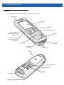
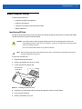
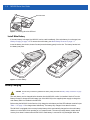
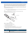
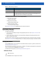
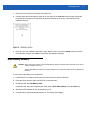
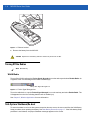

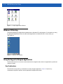
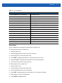
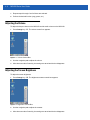
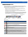
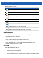
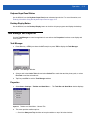
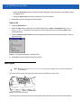
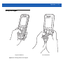
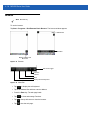


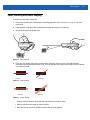
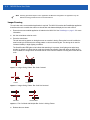


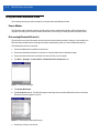
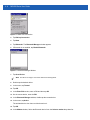
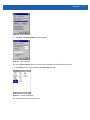
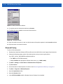
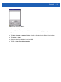

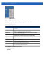

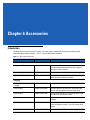
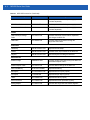
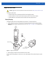
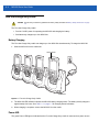
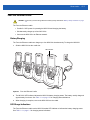

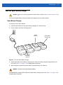
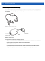
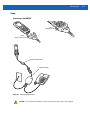
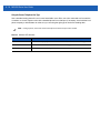
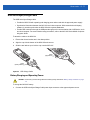
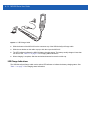

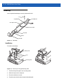
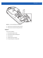
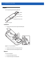
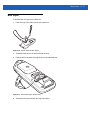

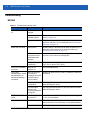

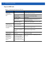
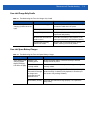
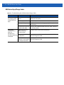
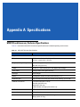
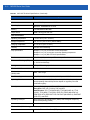
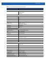


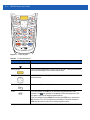
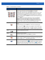
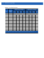


![Computador Móvel Série Mc21xx [Brazilian Portuguese] (P/N 72E](http://vs1.manualzilla.com/store/data/006087352_1-52d3c07a3e5093c41c1bf9fa502f7170-150x150.png)


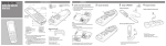

![MC92N0-G User Guide {English] (P/N 72E-162536-02](http://vs1.manualzilla.com/store/data/005752413_1-5c9790f7378b6b81af8236dfa051ab67-150x150.png)