1
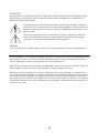
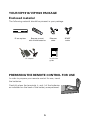
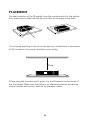
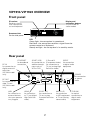
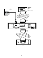
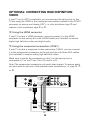
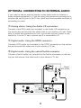
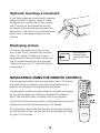
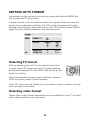
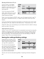
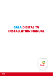
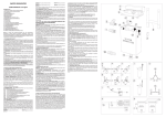
Installation Manual VIP1910/VIP1920 Caring for the Environment by Recycling When you see this symbol on a Motorola product, do not dispose of the product with residential or commercial waste. Recycling your Motorola Equipment Please do not dispose of this product with your residential or commercial waste. Some countries or regions, such as the European Union, have set up systems to collect and recycle electrical and electronic waste items. Contact your local authorities for information about practices established for your region. If collection systems are not available, call Motorola Customer Service for assistance. Declaration of Conformity We Motorola, Inc. Teknikringen 20 583 30 Linköping, Sweden declare under our sole responsibility that the Motorola VIP1910 and Motorola VIP1920 to which this declaration relates are in conformity with one or more of the following standards: EMC Standards EN55022 EN55024 EN50083-2 CISPR-22 CISPR-24 Safety Standards EN60065 EN60825 EN60950 IEC 60950 + A1: 1992 + A2: 1993 + A3: 1995 + A4: 1996 following the provisions of the Directive(s) of the Council of the European Union: EMC Directive 89/336/EEC Low Voltage Directive 73/23/EEC WEEE Directive 2002/96/EC CAUTION RISK OF ELECTRIC SHOCK CAUTION: TO REDUCE THE RISK OF ELECTRIC SHOCK, DO NOT REMOVE COVER (OR BACK). NO USER-SERVICEABLE PARTS INSIDE. REFER SERVICING TO QUALIFIED SERVICE PERSONNEL. WARNING TO REDUCE THE RISK OF FIRE OR ELECTRICAL SHOCK, DO NOT EXPOSE THIS APPLIANCE TO RAIN OR MOISTURE. Important Safety Instructions • Read these instructions. • Keep these instructions. • Heed all warnings. • Follow all instructions. • Do not use this apparatus near water. • Clean only with dry cloth. • Do not block any ventilation openings. Install in accordance with the manufacturer’s instructions. • Do not install near any heat sources such as radiators, heat registers, stoves, or other apparatus (including amplifiers) that produce heat. • Do not defeat the safety purpose of the polarized or grounding-type plug. If the provided plug does not fit into your outlet, consult an electrician for replacement of the obsolete outlet. • Protect the power cord from being walked on or pinched, particularly at plugs, convenience receptacles, and the point where they exit from the apparatus. • Use only attachments and accessories specified by the manufacturer. • Unplug this apparatus during lightning storms or when unused for long periods of time. • Refer all servicing to qualified service personnel. Servicing is required when the apparatus has been damaged in any way, such as when the power-supply cord or plug is damaged, liquid has been spilled or objects have fallen into the apparatus, the apparatus has been exposed to rain or moisture, does not operate normally, or has been dropped. CAUTION TO PREVENT ELECTRICAL SHOCK, DO NOT USE THIS PLUG WITH AN EXTENSION CORD, RECEPTACLE, OR OTHER OUTLET UNLESS THE BLADES CAN BE FULLY INSERTED TO PREVENT BLADE EXPOSURE. The lightning flash with arrowhead within an equilateral triangle is intended to alert the user to the presence of uninsulated dangerous voltage within the product’s enclosure that may be of sufficient magnitude to constitute a risk of electric shock. The exclamation point within an equilateral triangle is intended to alert the user to the presence of important operating and maintenance (servicing) instructions in the literature accompanying the product. Repairs If you find the unit in need of repair, contact your system operator for repair or replacement. © 2006 Motorola, Inc. All rights reserved. No part of this publication may be reproduced in any form or by any means or used to make any derivative work (such as translation, transformation, or adaptation) without written permission from Motorola, Inc. MOTOROLA and the Stylized M logo are registered in the US Patent and Trademark Office. All other product or service names are the property of their respective owners. Motorola reserves the right to revise this publication and to make changes in content from time to time without obligation on the part of Motorola to provide notification of such revision or change. Motorola provides this guide without warranty of any kind, implied or expressed, including, but not limited to, the implied warranties of merchantability and fitness for a particular purpose. Motorola may make improvements or changes in the product(s) described in this manual at any time. Your VIP1910/VIP1920 package Enclosed material TV W WW 2 9 INFO MENU ST O P BACK OK 7 4 0 1 8 5 TEXT 6 - 3 + The following material should be present in your package. IP set-top box Remote control with 2 AAA batteries Ethernet cable SCART cable Ins tallation G uide VIP1100 AC adaptor Installation guide Preparing the remote control for use In order to prepare your remote control for use, insert the batteries. Carefully place the terminals (+ and -) of the batteries as indicated on the back of the battery compartment. Placement For best reception of the IR-signals from the remote control to the set-top box, make sure to place the set-top box close to the edge of the shelf. Do not place anything on top of the set-top box, instead leave a free space of 20 cm above it for proper ventilation and cooling. 20 cm When using the remote control, point it to the IR-receiver in the center of the front panel. Make sure that there is no obstacle between the remote control and the set-top box, such as for example a table. VIP1910/VIP1920 overview Front panel IR receiver Receives signals from remote control and keyboard. Display and navigation buttons Only available on some models Smartcard slot On the side panel LED Green light - the set-top box is operational. Red flash - the set-top box receives a signal from the remote control or a keyboard. Steady red light - the set-top box is in stand-by mode. Rear panel RF IN for connection to digital terrestrial television. (VIP1920 model only) ETHERNET for broadband connection SCART (VCR) for connection to additional equipment such as VCR or DVD VCR ETHERNET S/PDIF for connection to digital audio equipment Y, Pb and Pr (Component video) for connection to TV set (analog High Definition video) Y S/PDIF Pb L Pr R RF - IN RF OUT for connection to older TV sets. (VIP1920 model only) USB for connetion to external devices that your operator may suggest HDMI POWER TV RF - OUT USB HDMI for connection to TV set (digital High Definition video) +5.7V DC 0V POWER for connection to power outlet TOSLINK SCART (TV) for connection to TV set (analog Standard Definition video) AUDIO L/R for connection to HiFI equipment or TV set (analog stereo audio) TOSLINK for optical connection to digital audio equipment Installing the VIP1910/VIP1920 j Connecting to broadband Connect one end of the Ethernet cable to the connector marked ETHERNET on the rear panel of the set-top box and the other end to a hub or the Ethernet wall connector provided by your broadband operator. k Connecting to the TV set Connect one end of the enclosed SCART cable to the SCART connector marked TV on the set-top box and the other end to your TV set. Both analog audio and standard definition video are sent to the TV set through this connection. l Optional: Connecting to a VCR or digital video recorder You can record the program you are currently watching by connecting an auxiliary device, such as a VCR or a digital video recorder, to the VIP1910/ VIP1920, provided that the program is copy-approved content. Connect the set-top box to the auxiliary device using the SCART connector marked “VCR”. To record, change to the TV channel on the set-top box you wish to record and start recording on the device. To watch recorded video, first put the set-top box in stand-by mode, and then press play on the auxiliary device. Optional: VCR or DVD recorder j Broadband wall outlet or hub l VCR ETHERNET Y S/PDIF Pb L Pr R RF - IN HDMI POWER TV RF - OUT USB +5.7V DC 0V TOSLINK k Y Pb Pr TV Optional: Connecting High definition Video If your TV set is HDTV compatible, you can connect the set-top box to the TV set using the HDMI or the component connectors instead of the SCART connector to receive and display HDTV, i.e. skip installation step k and replace it with installation step m or n. m Using the HDMI connector If your TV set has a HDMI connector, you can connect it to the HDMI connector on the set-top box with a HDMI cable (not included) to receive digital high definition video and digital audio. n Using the component connectors (YPbPr) If your TV set has a component video connectors (YPbPr), you can connect it to the component connectors on the set-top box with three RCA cables (not included) to receive analog high definition video. Make sure to match the connectors so that Y on the set-top box is connected to Y on the TV set, Pb to Pb and Pr to Pr. Note! The component connectors only send video signals. To receive audio you also need to use one of the possible audio connections, i.e. step o, p or q. n ETHERNET RF - IN VCR Y S/PDIF Pb L Pr R HDMI POWER TV RF - OUT USB +5.7V DC 0V TOSLINK m Y Pb Pr TV 10 Optional: Connecting to External Audio If you want to use an external source to play audio such as a stereo or home cinema equipment or if you are using the component connectors to connect the set-top box to the TV set, there are three possible methods of connecting to audio. o Analog stereo: Using the Audio L/R connectors Connect a dual RCA cable (not included) to the Audio L/R connectors on the set-top box and connect the other ends to your stereo or TV set. Make sure to match the connectors so that L on the set-top box (white) is connected to L on the TV set or stereo and R is connected to R. p Digital audio: Using the SPDIF connector Connect a RCA cable (not included) to the SPDIF connector on the set-top box and connect the other end to your stereo or TV set. q Digital audio: Using the optical Toslink connector Connect a Toslink cable (not included) to the Toslink connector on the settop box and connect the other end to your stereo or TV set. L S/PDIF 1 S/PDIF 2 R Stereo/ HiFi system p VCR ETHERNET Y S/PDIF Pb L Pr R RF - IN HDMI RF - OUT o USB POWER TV +5.7V DC 0V TOSLINK q 11 Digital Terrestrial tv (VIP1920 model only) r Connecting to Digital Terrestrial TV Connect one end of a RF cable (not included) to the RF-IN connector, and the other end to the antenna outlet in your home. You will now be able to receive TV channels broadcasted over the digital terrestrial network. For information on how you proceed with the channel search and scanning, please see separate instructions from your operator. Digital TV outlet/Antenna VCR ETHERNET Y S/PDIF Pb L Pr R RF - IN r HDMI POWER TV RF - OUT USB +5.7V DC 0V TOSLINK Connecting to power s Connecting to power When all other cables are connected, connect the power cord to the power connector on the set-top box and to mains power. VCR ETHERNET Y S/PDIF Pb L Pr R RF - IN HDMI POWER TV RF - OUT USB +5.7V DC 0V TOSLINK s 12 Power Optional: Inserting a smartcard If you have received a smartcard to enable access to the TV signals, insert it in the smartcard slot on the side of the set-top box. The chip on the smartcard should be directed downwards and towards the set-top box. The card is fully inserted when only 5 mm of the card remains on the outside. Displaying picture To display the signal from the set-top box on the TV set, switch to an external input. (On some TV sets this is done automatically.) There is often a button on the TV remote control for this purpose. Otherwise, see your TV User’s Guide for instructions. An example of what the input symbol may look like. Navigating using the remote control The navigation buttons (four arrow buttons and a OK button) are used to move around on Service portal pages and in menus, and to select the highlighted alternative. The navigation buttons are also used to navigate web pages, as the arrows move the indicator between the different links. Use the OK button to select links to be opened. The scroll buttons are used when a web page contains more information than can be displayed on a TV screen. For information about the functionality of the other buttons on the remote control, please see the information provided by your IPTV provider. 13 Setting up TV format Immediately as the set-top box is starting, press and hold the MENU button to enter the TV setup menu. A screen similar to the one below should now appear. While you view the set-top box configuration window, the LED on the front panel will toggle between red and green light each second. The LED will also flicker red and green for every button pressed on the remote control. Selecting TV format Start by selecting the the TV color system format that is used. Press OK button enter the TV system settings, and choose between PAL and NTSC with the up() and down() buttons. PAL is the standard primarily used in Europe, whereas NTSC is primarily used in North America. Press OK when your are standing on your chosen format to select it and go back one step in the menu. Selecting video format Select video output format depending on the capabilities of your TV set and what video connectors you are using. 14 Standard Definition TV set If your TV set is a standard definition TV set (not HDTV capable), press arrow down() button to mark “SD Output” and press OK. If you are using the SCART cable, select with arrow up() and down() buttons which video format you prefer. Note: if you are using the SCART cable, you will always be able to see TV and video in standard resolution, no matter what video format you have chosen. If you are using the component connectors on the set-top box with a standad definition TV set, select the third alternative - Component set to “ON” Press OK when your are standing on your chosen format to select it and go back one step in the menu. High Definition TV set If your TV set is HDTV enabled and it is connected to set-top box using the HDMI or component video connectors on the set-top box, please refer to your TV set specification to learn what resolution it supports. If you can’t find the resolution, we recommend that you use the setting of 720p HD output. Press OK on your selected choice. Saving the settings/Exiting settings Press BACK to go back to the left main menu to exit the settings window and press down () and OK to select Exit You will now be prompted if you wish to save your settings. Choose “Save and reboot” if you wish to save your settings or “Reboot without saving” if you want to discard them. The box will now be rebooted regardless if anything has been changed or not. 15 Starting up When the set-top box is connected to the TV set, Ethernet and power, you will see an image similar to the one to the right on the TV screen. The set-top box is now connecting to the network and downloading the software needed. Please wait until the loading is finished. The dots in the middle of the screen will change color during the start up of the system. From the start, all dots are dark grey. As the set-top box searches for software or is processing downloaded software, one dot at a time starts blinkning yellow. When software is being downloaded, a progress bar of ten smaller dots appear and the main dot blinks green. When one of the five steps in the start up process is completed, the dot for it turns green. When all five main dots are green, the system is ready to run. If the software in any of the steps could not be loaded, the dot turns red and the remaining steps are cancelled. Trouble shooting If you encounter any problems during start up, please note which of the main dots (1 - 5) that has not turned green before you contact your support personnel. On-line help When your set-top box is up and running, please see the instructions provided by your IPTV provider on how to reach the services and how to access the User’s Guide. Motorola, Inc. Teknikringen 20 583 30 Linköping, Sweden http://www.motorola.com 06/06 |6117310232R1BE~